1
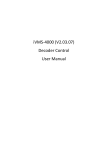
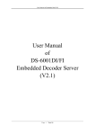
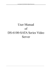
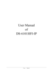
User Manual
Of
DS-600xDI
Network Decoder
(Ver3.0)
Statements
Thanks for purchasing our products, please contact us anytime if you have questions or requests.
The manual is applicable to the use of model DS-600xDI Network Decoder.
There may be technical inaccuracies, or typographical errors etc. in the manual. We will update the contents including description of products and program due to the enhancement of products function. The updates will be in the
new version of the manual without notice.
Page 1 of 18
LIST
Open the package and check the following accessories carefully:
¾
A Decoder
¾
A User Manual
¾
A Power Line
¾
A Contaminated Materials Table
¾
A Warranty Card
¾
A Certificate
¾
A CD-R
Please contact the distributor in time if the damage or shortage of accessories happened.
Page 2 of 18
Index
LIST........................................................................................................................................................................................................................................................... 2
Chapter1 Product Description.................................................................................................................................................................................................................... 5
1.1 Product Introduction.................................................................................................................................................................................................. 5
1.2 Model Description..................................................................................................................................................................................................... 5
1.3 Main Features ........................................................................................................................................................................................................... 5
Chapter2 Installation Guide ....................................................................................................................................................................................................................... 6
2.1 Attentions ................................................................................................................................................................................................................. 6
2.2 Panel Description ...................................................................................................................................................................................................... 6
2.3 The pin definition of physics interfaces ...................................................................................................................................................................... 8
2.3.1 PIN definition of RS-232 serial interface ............................................................................................................................................................. 8
2.3.2 PIN definition for RJ-45 connector of RS-485 serial interface .............................................................................................................................. 9
2.3.3 10M/100M Adaptive UTP network connect cable making method........................................................................................................................ 9
2.3.4 Connection methodology .................................................................................................................................................................................. 10
Chapter3 Parameters Configuration......................................................................................................................................................................................................... 11
3.1 Network Parameters Configuration .......................................................................................................................................................................... 11
3.1.1 Hyper Terminal Setup....................................................................................................................................................................................... 11
3.1.2 Configuration by Hyper Terminal...................................................................................................................................................................... 14
Page 3 of 18
3.2 Configuration by Client Software............................................................................................................................................................................. 16
Appendix I
DS-600xDI Specifications ............................................................................................................................................................................................. 18
Page 4 of 18
Chapter1 Product Description
1.1 Product Introduction
DS-600xDI Series Decoder is a network decoder that designed especially for the deployment and management of video monitoring system. DS-600xDI has a mature network function, and support a variety of network
transmission protocols. It’s also with the powerful decoding engine which can support multiple encoding formats. One device supports multi-channels decoding brings about deployment costs decrease of video monitoring system.
DS-600xDI adopts embedded system that makes whether device or the system more stable, efficient and safer.
1.2 Model Description
According to the difference of output channels, DS-600xDI Series has three models as follows:
¾
¾
¾
DS-6001DI: 1 channel video/audio output, support up to 4CIF video resolution;
DS-6004DI: 4 channels video/audio output, support up to 4CIF video resolution;
DS-6008DI: 8 channels video/audio output, support up to 4CIF video resolution.
1.3 Main Features
Network function
z
Support Static Network IP Settings.
z
Support DHCP Automatic Access to the Network IP Configuration.
User Settings
z
Support one administrator setting up several operators and independent rights for each one, which enhancing the flexibility of operator's safety management.
Transparent Access System
z
Support establishment of Transparent Access between Decoder and front-end DVR.
z
Support one local serial establishing multiple transparent accesses which can connect several front-end DVRs simultaneously.
Decoding
z
z
z
z
Support multi-channels decoding, support up to 4CIF resolution, 2Mbps bit rate.
The 4th and 8th channels support up to 16 screens circle decoding. Decoder with single channel supports up to 4 screens circle decoding. The circle period is configurable.
Decoder with single channel supports 4CIF resolution one screen decoding, which also can be set as CIF 4 screens or 2CIF 2 screens decoding.
Support TCP/IP, UDP network transmission protocols.
Development Support
z
Provide SDK of DVS Operation.
z
Provide demo of application software source code for speeding up system development.
Page 5 of 18
Chapter2 Installation Guide
2.1 Attentions
¾
Please read this guide carefully before installation.
¾
Be sure to shut down all the related power supplies of equipment.
¾
Check the voltage of power supply to prevent the device damage due to the voltage mismatching.
¾
Installation Environment: Do not use it under humidity or with high temperature, maintain good ventilation, avoid blocking the vents.
¾
Place horizontally, prevent installation occurred in the vibration surroundings.
¾
Placing containers with liquid such as vase on the device is not allowed.
[Note] Please get into contact with the supplier if there are any questions.
2.2 Panel Description
DS-6001DI:
Page 6 of 18
①
②
③
④
⑤
⑥
RS-232 Serial Interface;
VOUT Video Output Interface;
AOUT Audio Output Interface;
UTP Network Interface (with LAN);
RS-485 Serial Interface;
DC +12V Power Supply Interface.
DS-6004DI/DS-6008DI (take DS-6008DI for example):
Page 7 of 18
Rear Panel Description:
① VOUT Video Output Interface, AOUT Audio Output Interface;
② RS-232 Serial Interface;
③ ETHERNET Network Interface (with LAN);
④ RS-485 Resistance Matching Switch;
⑤ 485 Serial Interfaces;
⑥ Ground Terminal
⑦ 110V-240V AC Power Supply Interface.
2.3 The pin definition of physics interfaces
2.3.1 PIN definition of RS-232 serial interface
DS-600xDI series decoder has one RS-232 standard serial interface, with RJ-45 connector. Its pin definition is as follows (‘I’ means input, and ‘O’ means output):
Page 8 of 18
Cable connects DS-600xDI with PC, one end of the cable is the 8-pin RJ45 connector and the other is DB9 connector.
2.3.2 PIN definition for RJ-45 connector of RS-485 serial interface
¾
RXD+ : Signal Receive +
¾
RXD- :
Signal Receive When serial keyboard is connected with RS-485 of DS-6001DI, generally decoder only needs to be receiving order signals.
2.3.3 10M/100M Adaptive UTP network connect cable making method
(1) PIN definition of the direct network cable connecting with switchboard and HUB:
Page 9 of 18
(2) PIN definition of the cross network cable connecting with DVS and host PC:
2.3.4 Connection methodology
There are green curved pins with DS-6004DI, DS-6008DI decoder, connection steps are as below:
1. Pull out green curved pins from the device;
2. Loosen the screws by screwdriver, put signal line into the pin below the leaf spring, and tighten these screws;
3. Then insert the pin into the corresponding jack.
Page 10 of 18
Chapter3 Parameters Configuration
After hardware installation, firstly some network parameters of the server need to be configured, and then the video parameters configuration through client software.
3.1 Network Parameters Configuration
The parameters which need DS-600xDI decoder to configure are including: Decoder IP address, Subnet mask, Port, etc. You can configure them by Windows Hyper Terminal or NetTerm software.
Decoder IP address is mainly configured by Hyper Terminal or RS-232 serial, the default IP address of DS-600xDI is 192.0.0.64. If the decoder IP address is unknown, you can only configure it by Hyper Terminal or NetTerm
(serial ports connection is needed). More details are as below:
Please direct connect the RS-232 serial of PC with the RS-232 serial of DS-600xDI decoder before configuration.
3.1.1 Hyper Terminal Setup
Step 1: Enter Hyper Terminal.
Click “Start”Æ“Programs”Æ“Accessories”Æ“Communications”Æ“Hyper Terminal” in Windows system, and the dialogue box below will appear:
Step 2: Name the connection title and define the icon.
Input a name (e.g. aa), select an icon; press “OK”, and the connection dialogue box will appear.
Step 3: Select the communication port.
Page 11 of 18
Select “com1” communication port shown as above, press “OK”, the dialogue box will appear as below.
Step 4: Port Settings
Set port parameters in com1 properties as shown in figure below:
Page 12 of 18
Bit Rate: 115200
Data Bits: 8
Parity: None
Stop bits: 1
Flow control: None.
Press “OK” after finishing setting, the Hyper Terminal interface as figure below will appear:
Page 13 of 18
Step: Disconnect and Save Session.
According to the tips, disconnect and save session “aa” for the next time.
After saving, there will be a new “Hyper Terminal” item established in the program group “Start” Æ “Programs”Æ “Accessories”Æ “Communications” Æ “Hyper Terminal” and “Connection” names of all Hyper Terminal are
included. Here you can see an icon named “aa”.
3.1.2 Configuration by Hyper Terminal
Enter Hyper Terminal
Click “Start”Æ“Programs”Æ“Accessories”Æ“Communications”Æ“Hyper Terminal”Æ“aa”, then the Hyper Terminal interface will appear as figure below. Type Enter, and the prompt “Embedded Decoder” will appear which
means connection between RS-232 interface of PC and RS-232 interface of DS-600xDI is established successfully by Hyper Terminal. The following operation commands are to accomplish the parameters setup in the prompt.
Page 14 of 18
help
Type “help” and enter, then the list of configuration commands will be seen as below:
¾
¾
¾
¾
¾
¾
¾
¾
¾
help:
console help command, Syntax: help “Shell command name”, Note: The shell command name is a string, it needs double quotation marks
ifshow:
Show information of Ethernet.
getIp:
Show the configuration of network;
setIp: Configure the network;
ping:
ping remote host IP;
reboot:
reboot device and save current user settings;
linksur: link to remote surveillance device;
stopdec: stop a decoder channel;
version: show version information.
More details below about usage of getIp, setIp commands.
getIp
Function: Show the configuration of network.
Format: getIp
Note: Case-sensitive.
Page 15 of 18
setIp
Function: Configure the network. System will shut down access to DHCP mechanism automatically and switch to static network configuration mode.
Format: setIp “IP address”, “Subnet Mask”, “Default Gateway”, “ Main DNS”, “Stand-DNS”, “Command Port”, “http P”
Note: Case-sensitive.
E.g. if you need to set IP address: 192.168.0.8, Subnet Mask: 255.255.248.0, Gateway: 192.168.0.1, input setIp “192.168.0.8”, “255.255.248.0”, “192.168.0.1”, and type Enter to finish setting.
If you just want to set IP address of decoder: 192.168.0.188, Subnet Mask: 255.255.250.0, then input setIP 192.168.0.188: 255.255.250.0, and type Enter to finish setting.
Note: Case-sensitive, parameters need to be separated by commas.
3.2 Configuration by Client Software
Please confirm before configuration:
¾
PC and decoder are connected by network line;
Page 16 of 18
¾
You have already got IP address of the decoder by Hyper Terminal and confirm that you can use PING command.
Note: Please refer to the corresponding sections of client software for more details.
Page 17 of 18
Appendix I
DS-6001DI
Video compression
Audio compression
Decode resolution
Video output
Video
output
interface
Frame rate
Stream type
Audio output
Audio
output
interface
Communication
interface
Power supply
Power consumption
Working humidity
Dimension (mm)
Weight
1 channel
1 channel
RCA (Linear, 600Ω)
DS-600xDI Specifications
DS-6004DI
H.264
OggVorbis
QCIF/CIF/2CIF/DCIF/4CIF
4 channels
BNC(1.0Vp-p,75Ω)
DS-6008DI
8 channels
PAL: 1/16~25 FPS; NTSC: 1/16~30 PBS
Video stream/Video & Audio stream
4 channels
8 channels
BNC (Linear, 600Ω)
1 RJ45 10M/100M Adaptive Ethernet port, 1 RS-232 interface, 1 RS-485 interface
DC 12V
10W
AC 110V~240V
40W
10%~90%
235(W)*136(D)*43(H)
2Kg
419(L)*238(D)*76(H)
5Kg
Page 18 of 18