1
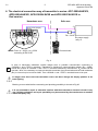
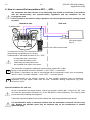
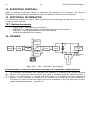
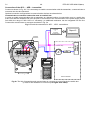
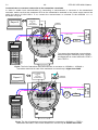
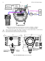
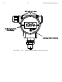
C1 5 DTR.APC.APR.ALW.03(ENG) Appendix Exd.ATEX 6. The electrical connection way of transmitter’s series: APC-2000ALW/XX, APR-2000ALW/XX, APR-2200ALW/XX and APR-2000YALW/XX in Exd version Hazardous area Safe area + short-circuit( jumper) _ TEST + _ +SIGNAL Ro _ TEST Ex power supply see p.5. RD F1 F2 F3 PF RE F4 DEF GHI @%& JKL MNO PQR +/ STU VWX YZ# . 7 Fuse: In = 0,05A, Un = 250V according to EN 60127 F4 PV ABC 4 1 8 5 2 9 6 3 0 * Communicator Fig. 2. i In case of transmitter calibration outside danger zone is possible communicator connecting to <SIGNAL+> and <TEST+> terminals. Transmitter is furnished in communication resistor (RD = 240Ω), closed with jumper at <SIGNAL-> and <TEST-> terminals installed by manufacturer. RD resistor can be use then, when it is necessary to communicate with transmitter from its terminals and the load resistance (Ro) in current loop is lover then 240Ω. Than <SIGNAL-> and <TEST-> terminals have to be open. In danger zone don’t unscrew transmitter covers and don’t change the display position or its back lighting. Blocking cover method before unscrewing and plumbing possibility is shoved at Fig.20. It is not permitted to repair or otherwise interfere with the transmitter’s electrical circuits in any way. Damage estimation and repair possibility may be assessed by the manufacturer or another authorized party only.