1
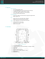
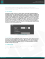
User Manual Version 0.3 Preliminary Release Copyright © 2013 x-‐io Technologies Ltd. www.x-‐io.co.uk x-‐OSC User Manual v0.3 Release date: 18 November 2013 Contents 1. Overview ............................................................................................................................................. 3 2. Open Sound Control (OSC) .................................................................................................................. 3 3. Features .............................................................................................................................................. 4 4. Hardware ............................................................................................................................................ 4 4.1. Input Connections ....................................................................................................................... 5 4.2. Output Connections .................................................................................................................... 5 4.3. Ping button .................................................................................................................................. 5 4.4. Status LED .................................................................................................................................... 5 5. Connecting to x-‐OSC ........................................................................................................................... 5 5.1. Ad hock Mode (Cyan LED) ........................................................................................................... 6 5.2. Infrastructure Mode (Yellow LED) ............................................................................................... 6 6. Browser Configuration ........................................................................................................................ 6 6.1. Network Settings ......................................................................................................................... 7 6.2. OSC Settings ................................................................................................................................ 8 6.3. Input Settings .............................................................................................................................. 8 6.4. Output Settings ............................................................................................................................ 8 6.5. Serial Settings ............................................................................................................................ 10 6.6. IMU Settings .............................................................................................................................. 10 7. Communicating with x-‐OSC – OSC Dictionary ................................................................................... 10 7.1. x-‐OSC to host messages ............................................................................................................. 11 7.2. Host to x-‐OSC messages ............................................................................................................ 11 www.x-‐io.co.uk 2 / 12 © 2013 x-‐OSC User Manual v0.3 Release date: 18 November 2013 1. Overview x-‐OSC is a wireless I/O board that provides access to 32 high-‐performance analogue/digital channels via Open Sound Control (OSC) over Wi-‐Fi. There is no requirement for user programmable firmware nor specific drivers, making x-‐OSC immediately compatible with any Wi-‐Fi-‐enabled platform. All you need is a Wi-‐Fi enabled computer, some basic programming skills and you are ready to make sophisticated interactive systems. 2. Open Sound Control (OSC) x-‐OSC communications take place over Wi-‐Fi using the widely supported OSC message format, which is a versatile and lightweight protocol supported by more than 80 different programming languages and software environments. For an extensive list see: http://opensoundcontrol.org/implementations We are also maintaining a growing range of x-‐OSC example projects for the most popular platforms/environments here: http://x-‐io.co.uk/x-‐osc www.x-‐io.co.uk 3 / 12 © 2013 x-‐OSC User Manual v0.3 Release date: 18 November 2013 3. Features Inputs / Outputs • 16× analogue/digital inputs • 16× digital/PWM/pulse outputs (upto 50 mA per channel) • 13-‐bit ADC with 400 Hz update rate per channel • Up to 16-‐bit PWM resolution for 5 Hz to 250 kHz • 4× serial communication channels On board sensors • Gyroscope (±2000°/s), accelerometer (±16 g) and magnetometer • 400 Hz update rate Wi-‐Fi • High-‐performance Wi-‐Fi (802.11b/g, 54 Mbps) • Supports ad hoc and infrastructure networks • Fully configurable via standard internet browser. Other • Small form factor: 45 x 32 mm • Regulated 3.3V, 700 mA output • Battery level monitor 4. Hardware 1 5 7 4 3 8 2 6 7 Figure 1: x-‐OSC top view 1. 2. 3. 4. 5. 6. 7. 8. www.x-‐io.co.uk 16 analogue/digital inputs 16 digital outputs (inc. high-‐speed PWM for ‘analogue’ output) Ping button Status LED Regulated power out (3.3 V) Battery output or power input (3.5 – 5.5 V) Ground (0 V) Battery connector 4 / 12 © 2013 x-‐OSC User Manual v0.3 Release date: 18 November 2013 4.1. Input Connections x-‐OSC is equipped with 16 independent input channels, which may each be configured to either analogue, digital or serial (inputs 1 to 4 only) modes, using a browser or OSC over Wi-‐Fi (see sections 6.3 and 6.1). Digital inputs can be configured to use internal pull-‐up/down resistors and, to minimise latency, their state is only transmitted on change. Analogue inputs may be connected to sensors producing a voltage in the range 0 – 3.3 V. Each input is sampled with 13-‐bit resolution and measurements are transmitted at a specified rate of up to 400 Hz. Analogue input mode also provides a ‘compare’ function to send a message each time a specified threshold is crossed. This enables low-‐latency threshold detection without the need for a high message rate. The serial channels support baud rates up to 2Mbps, with 8 data bits, no parity and 1 stop bit. Serial data can be framed by specifying a buffer size, data timeout and/or a framing byte. When a complete frame has been received it is transmitted as an OSC blob. 4.2. Output Connections The 16 independent output channels on x-‐OSC may each be configured to output digital, pulse, PWM or serial (outputs 1 to 4 only) signals, which can also be configured by browser or OSC over Wi-‐Fi (see sections 6.3 and 6.1). In digital mode, an output can be set high or low. In pulse mode, an output can be triggered to generate a pulse with a period of 1 ms to 1 minute at a resolution of 1 ms. An output in PWM mode can generate a PWM waveform from 5 Hz to 250 kHz with a duty cycle resolution up to 16-‐bit. PWM may be used with a fixed frequency and variable duty cycle to approximate an analogue signal. Serial output data is sent using the same configuration as the serial inputs. To transmit serial data the host application should format the data into an OSC blob message. 4.3. Ping button The ping button on the x-‐OSC board serves a number of purposes. When pressed x-‐OSC responds by broadcasting an OSC message indicating its IP and MAC address. Pressing and holding for 3 seconds causes x-‐OSC to toggle network modes; that is, if it is in ad hoc mode it switches to infrastructure mode, and vice versa (see section 5). Pressing and holding the ping button for longer than 8 seconds invokes a factory reset when the button is released. 4.4. Status LED The LED on x-‐OSC indicates the current network mode: cyan for ad hoc mode and yellow for infrastructure mode (see section 5). In ad hoc mode, the LED will flash until its network has been created; in infrastructure mode the LED will flash until it has joined the infrastructure network. If x-‐ OSC fails to join the infrastructure network, return to ad hoc mode by pressing and holding the ping button as described in section 4.3. It is also possible to override the LED colour if desired, see section 7. 5. Connecting to x-‐OSC x-‐OSC can communicate with one or more host computers over a Wi-‐Fi network in either ad hock or infrastructure network modes. By default the device uses ad hock mode, although this can be changed easily using a standard internet browser (see section 6). While the network connection is being established the LED will flash; upon successful network configuration the LED will remain on constantly. www.x-‐io.co.uk 5 / 12 © 2013 x-‐OSC User Manual v0.3 Release date: 18 November 2013 5.1. Ad hock Mode (Cyan LED) In ad hoc mode x-‐OSC creates an open Wi-‐Fi network that other devices are able to join. By default this network is called “x-‐OSC” and will show up as an available Wi-‐Fi network in your computer’s network settings (this network name (SSID) can be changed in the device settings see section 6. At any time it is always possible to enter ad hock mode by pressing and holding the ping button until the LED begins to flash Cyan. 5.2. Infrastructure Mode (Yellow LED) Infrastructure mode allows x-‐OSC to connect to an existing Wi-‐Fi network. Open, WPA and WPA2 wireless security modes are supported and x-‐OSC can be configured to have a static IP address or to obtain one dynamically from the network server using DHCP. If x-‐OSC is issued an unknown IP address simply press the ping button (see section 4.3), which will cause x-‐OSC to broadcast an OSC message indicating its network configuration on its outgoing port (8000 by default). Alternatively, another network device can broadcast a ping OSC message to achieve the same result. Infrastructure mode enables multiple x-‐OSC’s to operate on the same network and to be addressed by one or more host computers also connected to the network. 6. Browser Configuration Figure 2: x-‐OSC browser settings www.x-‐io.co.uk 6 / 12 © 2013 x-‐OSC User Manual v0.3 Release date: 18 November 2013 x-‐OSC can be configured over Wi-‐Fi using an internet browser. Simply open your preferred browser and in the address bar type in x-‐OSC’s IP address. If x-‐OSC is in ad hock mode, and you are connected to its network, this will be http://169.254.1.1. If x-‐OSC is in infrastructure mode you can obtain the IP address by pressing the ping button and listening for an OSC message on x-‐OSC’s outgoing port number (8000 by default). If at any time you are unable to connect to x-‐OSC, simply press and hold the ping button for three seconds to return the device to ad hock mode with an open network; you can then access the settings page by joining its network and navigating to http://169.254.1.1 The remainder of this section will briefly explain x-‐OSC’s browser settings page. Note that changes made to any of these settings are only applied when the `Save Settings’ button is pressed. 6.1. Network Settings In the Network section, x-‐OSC can be switched between ad hock and infrastructure modes (see section 5). In ad hock mode (cyan LED) the network name (SSID) of the x-‐OSC hosted Wi-‐Fi network can be set. Figure 3: Ad hock network browser settings In infrastructure mode you can enter the name of the network (SSID) that you would like x-‐OSC to join, setting the security mode accordingly. Figure 4: Infrastructure network browser settings Security types Open and WPA/WPA2 are supported where the latter option requires entry of a security passphrase. In this section you can disable DHCP if you would like to specify a static IP address for x-‐OSC. When you are happy that you have entered the correct infrastructure settings click the ‘Save Settings’ button to reboot x-‐OSC with the new settings. The LED will then flash yellow until it has successfully joined the network when it will shine constantly. Connection should take www.x-‐io.co.uk 7 / 12 © 2013 x-‐OSC User Manual v0.3 Release date: 18 November 2013 approximately 30 seconds, if flashing continues for more than one minute then review the infrastructure settings for errors by pressing and holding the ping button for 3 seconds to revert back to ad hock mode, see section 5 above. 6.2. OSC Settings In the OSC section, the IP and port settings for the receipt and delivery of OSC messages may be configured. The host IP is the address to which x-‐OSC will send messages. The default IP address is 255.255.255.255, which is a special broadcast address meaning that every device on the network will receive the messages. The outgoing port specifies the port on which your computer should listen for messages from x-‐OSC and the incoming port specifies the port on which your computer should send messages to x-‐OSC. The local IP shows x-‐OSC’s current IP address in a read only field. There are two further options in this section. When the ‘Send bundles’ option is checked, x-‐OSC will send messages formatted as OSC bundles, where the bundle time tag indicates a the acquisition time of the data (accurate to 14 ns). The `Use address prefix’ option allows you to specify a unique prefix address for all incoming and outgoing OSC messages. This option can be used to differentiate between messages received on the same port from multiple x-‐OSCs. Figure 5: OSC browser settings 6.3. Input Settings The input section is where individual input channels are configured is shown in Figure 6. At the top is the message rate for the analogue input readings (0.0 – 400.0 Hz). Beneath, each input channel can be configured as digital or analogue. Inputs 1 to 4 can additionally be set to serial as described in section 4.1. In digital mode the pull up/down state can be set, in analogue mode the comparator threshold can be set (range 0.0 – 1.0). 6.4. Output Settings The output section is where the individual output channel modes can be configured. Each channel can be set to digital, pulse or PWM modes with relevant parameters for each mode as shown in figure Figure 7 and described in section 4.2. www.x-‐io.co.uk 8 / 12 © 2013 x-‐OSC User Manual v0.3 Release date: 18 November 2013 Figure 6: Input browser settings Figure 7: Output browser settings www.x-‐io.co.uk 9 / 12 © 2013 x-‐OSC User Manual v0.3 Release date: 18 November 2013 6.5. Serial Settings The serial settings are where the four UARTs connected on input and output channels 1 to 4 may be configured. Each channel supports baud rates up to 2 Mbps, with 8 data bits, no parity and 1 stop bit. Serial data can be framed by specifying a buffer size (up to 2048 bytes), data timeout (up to 1000 ms) and/or a framing byte (0 to 255). Figure 8: Output browser settings 6.6. IMU Settings x-‐OSC is equipped with on-‐board 3D gyroscope, accelerometer and magnetometer. The IMU settings adjust the rate at which these sensor readings are transmitted over OSC (0 – 400 Hz). Figure 9: IMU browser settings 7. Communicating with x-‐OSC – OSC Dictionary x-‐OSC Implements OSC 1.0 as per the specification with the following exceptions/notes: • • • • the address pattern is not case sensitive. character lists (e.g. [“string]”) or the associated operators “-‐” and “!” are not supported. float and integer arguments are interchangeable for all Boolean arguments represented as integers, values less than or equal to 0 are false and values greater than 0 are true. This section provides a short look up table for the x-‐OSC OSC dictionary. www.x-‐io.co.uk 10 / 12 © 2013 x-‐OSC User Manual v0.3 Release date: 18 November 2013 7.1. x-‐OSC to host messages Address Pattern Arguments/Description /inputs/digital 16 integer arguments represent the state of the 16 digital inputs (0 or 1). Sent only when the state of any digital input pin changes /inputs/analogue 16 floating-‐point arguments indicate the analogue readings for all 16 inputs. Sent at the analogue input message rate /inputs/analogue/comparator 16 integer arguments represent the current compare state of the 16 analogue inputs (0 if below or 1 if above the threshold). Sent only when a threshold on any channel is crossed /inputs/serial/<channel> 1 blob argument containing the raw serial data received on input <channel> (1 -‐ 4) /imu 10 floating-‐point arguments indicating the current readings of the on board sensors. Arguments 1 – 3 gyroscope (°/s) x, y, z; arguments 4 – 6 accelerometer (g), x, y ,z; arguments 7 – 9 magnetometer (Ga) x, y ,z; argument 10 gyroscope temperature (°C) /battery 1 floating-‐point argument indicating the current battery voltage /ping 2 string arguments are the x-‐OSC local IP address (first argument) and MAC address (second argument) Table 1: x-‐OSC to host message summery 7.2. Host to x-‐OSC messages If x-‐OSC receives a message that does not match any message in the following table the LED will flash red. Address Pattern Arguments/Description /inputs/analogue/read prompts x-‐OSC to respond with an /inputs/analogue message /inputs/analogue/rate floating-‐point argument sets the message rate for the analogue input readings (0.0 – 400.0) /inputs/analogue/<channel> the input <channel> (1 -‐ 16) is set to analogue mode /inputs/analogue/comparator/read prompts x-‐OSC to respond with an /inputs/analogue/compare message /inputs/analogue/comparator /threshold/<channel> floating-‐point argument sets the comparator threshold (0.0 – 1.0) for the specified input <channel> (1 -‐ 16) /inputs/digital/<channel> sets the specified input <channel> (1 -‐ 16) to digital mode /inputs/digital/read prompts x-‐OSC to respond with an /inputs/digital message /inputs/digital/up/<channel> enables the pull up resistor for the specified digital input www.x-‐io.co.uk 11 / 12 © 2013 x-‐OSC User Manual v0.3 Release date: 18 November 2013 <channel> (1 -‐ 16) /inputs/digital/down/<channel> enables the pull down resistor for the specified digital input <channel> (1 -‐ 16) /outputs/digital/<channel> sets the specified output <channel> (1 -‐ 16) to digital mode /outputs/digital/state/<channel> integer argument (0 or 1) sets the state of the specified output <channel> /outputs/digital/pattern the lower 16-‐bits of the integer argument sets the state of all 16 digital outputs /outputs/pulse/<channel> triggers a pulse on the specified output <channel> (1 -‐ 16) is set to pulse mode. Uses the last width and invert values /outputs/pulse/width/<channel> integer argument sets the pulse duration in milliseconds (0 -‐ 60000) for the specified <channel>. Also triggers a pulse /outputs/pulse/invert/<channel> integer argument (0 or 1) sets the inversion state of the pulse (1 is inverted). Also triggers a pulse /outputs/pwm/<channel> the specified output <channel> (1 -‐ 16) is set to PWM mode /outputs/pwm/frequency/<channel> floating-‐point argument sets the PWM frequency (5 – 250 000) for the specified output <channel> (1 -‐ 16). Also sets the pin to PWM mode if not already /outputs/pwm/duty/<channel> floating-‐point argument sets the PWM duty cycle (0 – 100 %) for the specified output <channel> (1 – 16). Also sets the pin to PWM mode if not already /led/rgb three integer arguments (range 0 -‐ 255) set the RGB vales for the on board LED /led/default resets the LED to the network mode colour /ping causes x-‐OSC to broadcast its local IP address /inputs/serial/<channel> the specified input <channel> (1 -‐ 4) is set to serial mode /outputs/serial/<channel> the specified output <channel> (1 -‐ 4) is set to serial mode /serial/baud/<channel> integer argument (0 -‐ 2000000) sets the baud rate for the specified serial <channel> (1 -‐ 4) /serial/buffer/<channel> integer argument (1 – 2048) sets the input buffer size for the specified serial <channel> (1 -‐ 4) /serial/timeout/<channel> the timeout of the input buffer for the specified serial <channel> (1 -‐ 4) is set to the value of i (0 – 1000 ms) /outputs/serial/<channel> blob argument will be transmitted on the specified serial <channel> Table 2: host to x-‐OSC message summery www.x-‐io.co.uk 12 / 12 © 2013