1
BY, CAJ
3002
NAVAL POSTGRADUATE SCHOOL
Monterey
,
California
THESIS
PETRI NET MODELING AND AUTOMATED
SOFTWARE SAFETY ANALYSIS: METHODOLOGY
FOR AN EMBEDDED MILITARY APPLICATION
by
Alan D. Lewis
June 1988
Thesis Advisor:
Approved
Daniel
L.
Davis
for public release; distribution is unlimited.
T242045
Unclassified
security classification of this page
REPORT DOCUMENTATION PAGE
la
2a Secuntv Classification Authority
3
Distribution Availability of Report
5
Monitoring Organization Report Number(s)
Approved
2b Declassification Downgrading Schedule
4 Performing Organization Report Numberis)
Name of Performing Organization
Naval Post graduate School
(city, state,
Monterey'.
8a
Name
CA
and ZIP code)
~b Address
(city, slate,
CA
Monterey!
93943-5000
of Funding Sponsoring Organization
is
unlimited.
7a
33
(if applicable)
for public release; distribution
Name of Monitoring Organization
Naval Postgraduate School
6b Office Symbol
6a
6c Address
Markings
lb Restrictive
Report Security Classification I nclassiiied
8b Office Symbol
9
and ZIP code)
93943-5000
Procurement Instrument
Identification
Number
(if applicable)
Sc Address
(city, state,
and ZIP code)
10
Source of Funding Numbers
Program Element No
Project
No
Task
No
Work
Unit Accession
No
Title (include security classification, PETRI NET MODELING AND SOFTWARE SAFETY ANALYSIS: METHODOL
OGY FOR AN EMBEDDED MILITARY APPLICATION
li
12 Personal Author(s)
Alan D. Lewis
13b Time Covered
13a Type of Report
Master's Thesis
16
From
The views expressed
Supplementary Notation
sition
14 Date of Report {year, month, day)
To
15
Page Count
June 1988
98
in this thesis are those of the author
and do not
reflect the official policy
or po-
of the Department of Defense or the U.S. Government.
7 Cosati
Codes
18 Subject
Group
Field
19 Abstract
i
Subgroup
continue on reverse
if
Terms (continue on
reverse If necessary
and
identify by block
Petri nets, software safety, missile fuze, safety
necessary
and
identify by block
number)
arming device,
Petri
Net
Utilities,
P-NUT
number)
This thesis investigates the feasibility of software safety analysis using Petri net modeling and an automated suite of Petri
Net UTilities (P-NUT) developed at UC Irvine. We briefly introduce software safety concepts, Petri nets, reachability, and
the use of P-NUT. We then develop a methodology to combine these ideas for efficient and effective preliminary safety
analysis of a real-time, embedded software, military system.
20 Distribution Availability of Abstract
H
22a
unclassified unlimited
Name
D
same
21 Abstract Security Classification
as report
DTIC
Unclassified
users
of Responsible Individual
22b Telephone
Daniel L. Davis
DD FORM
1473,84
\
include
(408) 646-3390
MAR
83
APR
edition
may
be used until exhausted
Area code)
22c Office Svmbol
52Dv
security classification of this page
All other editions are obsolete
Unclassified
Approved
for public release; distribution is unlimited.
and Software Safety Analysis:
an Embedded Military Application
Petri Net Modeling
Methodology
for
by
Alan D. Lewis
Lieutenant, United States Navy
B.S., United States Naval Academy, 1980
Submitted in partial fulfillment of the
requirements for the degree of
MASTER OF SCIENCE
IN
ENGINEERING SCIENCE
from the
NAVAL POSTGRADUATE SCHOOL
June 1988
ABSTRACT
This
thesis
investigates
the
feasibility of
software
safety analysis using Petri net modeling and an automated
suite of Petri Net UTilities
(P-NUT)
developed at UC Irvine.
We briefly introduce software safety concepts,
reachability theory, and the use of P-NUT.
methodology
effective
to
combine
preliminary
these
safety
ideas
embedded software, military system.
111
We then develop a
for
analysis
Petri nets,
of
efficient
a
and
real-time,
TABLE
OF
CONTENTS
INTRODUCTION
II
III
IV.
V.
INTRODUCTION TO SOFTWARE SAFETY
.
.
4
A.
WHAT IS SOFTWARE SAFETY?
4
B.
INTRODUCTION TO SOFTWARE SAFETY ANALYSIS
5
PETRI
NETS AND
REACHABILITY
8
A.
INTRODUCTION TO PETRI NETS
B
PETRI NET THEORY
11
C
REACHABILITY
13
PETRI NET UTILITIES
(P-NUT)
8
15
A.
INTRODUCTION TO P-NUT
15
B.
TRANSLATING THE PETRI NET
16
C.
BUILDING AND PRINTING REACHABILITY GRAPHS
19
D.
REACHABILITY GRAPH ANALYZER (RGA)
21
THE
SYSTEM UNDER ANALYSIS
27
A.
A SOFTWARE-CONTROLLED REAL-TIME SYSTEM
27
B
SYSTEM BACKGROUND
27
C
SYSTEM OPERATION
29
IV
IJIA959
VI
MODELING AND ANALYSIS METHODOLOGY
.
VTI
.
33
A.
PROBLEMS IN SOFTWARE SYSTEM MODELING
33
B
A BOTTOM-UP APPROACH
34
1
ITL Sensor Module
35
2.
Analog to Digital Converter (ADC) Model
41
3
Solenoid Model
47
4
The System Petri Net Model
57
5.
P-NUT Aided Safety Analysis of System Model .... 62
RESULTS AND CONCLUSIONS
64
A.
RESULTS
64
B.
CONCLUSIONS
65
C
RECOMMENDATIONS
69
APPENDIX A
INTENT TO LAUNCH ITL SENSOR PETRI NET MODEL.. 72
APPENDIX B
ANALOG TO DIGITAL CONVERTER (ADC) PETRI
NET MODEL
73
APPENDIX C
SOLENOID PETRI NET MODEL
74
APPENDIX D
SOLENOID PETRI NET TEXT FILE
75
APPENDIX E
SOLENOID REACHABILITY GRAPH
77
APPENDIX F
SAFETY AND ARMING
SYSTEM
80
APPENDIX G
SA SYSTEM PETRI NET TEXT FILE
83
APPENDIX H
SUMMARY OF MODELING AND ANALYSIS METHODOLOGY
86
(SA)
LIST OF REFERENCES
88
INITIAL DISTRIBUTION LIST
90
INTRODUCTION
I.
are increasingly being used as passive
and active (controlling) components of realtime systems, e.g., air traffic control, aerospace,
and hospital patient
industrial plants,
aircraft,
The problems of safety become
monitoring systems.
important when these applications include systems where the
consequences of failure are serious and may involve grave
danger to human life and property. [Leveson and Stolzy,
Computers
(monitoring)
1987]
Unfortunately,
little
is
known
about
applying
safety
considerations to the design and evaluation of computercontrolled real-time systems.
The military relies heavily on
computer-controlled,
safety-critical,
real-time systems and
has published several standards for test and verification of
software system safety
1574A)
.
(MIL-STD-SNS,
MIL-STD-882B, MIL-STD-
MIL-STD-882B (DoD) contains requirements for software
hazard analysis and software safety verification, while MIL-
STD-1574A (USAF)
analysis
and
interfaces)
lists the requirements for software safety
integrated
system
(hardware,
software,
and
MIL-STD-SNS (USN) covers software safety
safety.
analysis for nuclear weapons systems.
Problems with ascertaining and verifying the safety of
software-controlled
system
include
the
difficulty
a
of
providing realistic test conditions and simulating hardware
errors, transient faults,
existing
facets,
language
such
as
which
and system interfaces.
incorporates
software,
hardware,
There is no
the
myriad
and
the
system
resulting
interfaces.
This overall
source
greatest
of
system view is critical,
problems
encountered
as the
computer
in
controlled systems may be the lack of system level methods.
[Leveson,
1986]
There are several proposed techniques for software safety
analysis,
including Petri net modeling
Fault Tree Analysis
1987],
Time Logic
(RTL)
[Leveson and Stolzy,
[Vesely et al
[Jahanian and Mock,
.
and Real-
1981],
,
1986]
This thesis
.
follows the Leveson and Stolzy use of Petri Net modeling and
the other techniques will not be discussed further.
For a
brief synopsis on the other methods, see Hayward [1987].
The system under investigation is a proposed air-to-air
guided missile safety and arming device,
Naval Weapons Center in China Lake,
this
particular
constructed,
a
This device
is
safety
developed at the
Although
California.
arming device
was
never
actually
software prototype was written and tested.
excellent
for developing
a
methodology to
analyze safety-critical computer/software-controlled systems.
The device is nontrivial,
contains embedded software, and if
designed incorrectly or tested ineffectively might result in
personal injury or unwanted property destruction.
This
Hayward
thesis
refines and continues the work of Duston
[1987],
who
initially
feasibility of using Petri nets,
[1987]
analysis
techniques
to
investigated the practical
and the Leveson and Stolzy
meet
military
standards.
with
Beginning
the
device
software
and verbal descriptions of the components,
assembler code,
Hayward
arming
and
safety
constructed
[1987]
system
and
system
software
flowcharts and Petri net models of system components.
then combined the flowcharts into
by conversion to
a
single system description
a
Using the safety and
Petri net model.
Hayward demonstrated techniques
arming device,
He
for manual
construction of partial reachability graphs and application
of Leveson and Stolzy [1987]
safety analysis methods.
Following publication of Hayward [1987], the U.
Postgraduate School received
a
set
S.
Naval
of automated Petri
net
analysis and utility tools from the Department of Information
and
Computer
Science,
[Morgan and Razouk,
University
1985; Razouk,
of
California,
1987; Morgan,
1987]
Irvine
.
These
utilities construct the reachability graph of an entered net
and support automated reachability analysis through use of a
sophisticated reachability graph analyzer.
Our work is the
first known application of these automated utilities to the
area of software safety analysis.
We begin with brief
Petri nets,
UTilities
introductions to software safety,
reachability theory,
(P-NUT)
.
We
discuss
Hayward [1987] model and develop
and effective
safety-critical,
and use of the Petri Net
preliminary
refinements
a
safety
made
to
the
methodology for efficient
analysis
software-controlled system.
of
a
complex,
INTRODUCTION TO SOFTWARE
II.
A.
WHAT
IS
SOFTWARE
SAFETY
SAFETY?
The American College Dictionary defines
quality of insuring against hurt,
injury,
safety as the
danger,
or risk.
It follows that software safety may be considered as freedom
from software causing danger or risk.
inherently safe,
Software, however,
is
since alone it can do no physical damage.
Although it is the hardware that the software controls which
actually presents the hazard,
hardware as
one
we must
treat
software and
entity for analysis purposes.
"Software
engineering techniques that do not consider the system as
whole,
including the
software,
interactions
and human operators,
between the
a
hardware,
will have limited usefulness
for real-time control software."
[Leveson,
1986]
The safety
of a software-controlled system is commonly referred to as
software safety.
Safety should not be confused with reliability.
is the
probability that
regardless
performed.
of
whether
a
or
Reliability
engineering community,
as
mishap
the
not
is
(accident)
function
defined,
in
is
the
the probability that the system
will accomplish its intended function for
under specified environmental
conditions
Konakovsky,
.
1978; Leveson,
will not occur
intended
normally
Safety
1986]
a
specified time
[Ericson,
1981;
These are quite different
concepts,
would
as demonstrated in the analysis of munitions.
that
expect
improved,
when
reliability
the
the weapon becomes less safe.
of
a
One
weapon
is
Improvements that
increase the probability of detonation may very well increase
the
likelihood
of
accidental
firing,
unless
specific
precautions are made in the design to improve the safety as
reliability
Leveson,
B
.
improved.
is
[Roland
and
Moriarity,
1983;
1986]
INTRODUCTION
TO
SOFTWARE
To ensure system safety,
SAFETY ANALYSIS
it is necessary to show that the
software and hardware will perform as required and verify
that the relationships between software, hardware, and system
behavior are correct.
Many of the system safety techniques that have been
developed to aid in building electromechanical systems with
minimal risk do not seem to apply when computers are
introduced.
The major differences appear to stem from the
lack of system-level approaches to building software
controlled systems.
[Leveson 1986]
Current system safety techniques do not consider human
design errors in system failures.
never to have
occurred or to have been removed prior to
delivery and operation.
systems
Human errors are assumed
and powerful
With the growth of embedded software
microprocessors,
the
complexity
of
software and hardware has grown tremendously and resulted in
a
nonlinear increase in human error design flaws.
Due to
it may be impossible to prove correctness
system complexity,
and safety of a realistic control system.
Based on this situation,
Leveson
[Lauber,
1980]
argued the need
[1986]
for a new approach to the software safety analysis problem.
The "black box" approach to software is not valid.
system concept must be employed to properly
A total
account
for
software effects on the system.
The initial stage of the analysis is to focus on system
failures that have the most drastic consequences.
especially
useful
in
situations
where
This is
system
the
under
investigation has relatively few failures leading to mishaps.
The technique is to start with a given set of unacceptable
failures and then by means of
that the
failures
[Leveson,
1986]
One
method
operators,
a
"backward" approach ensure
are eliminated,
combining
for
or
at
software,
and system interfaces
is
successfully
treats
all
hardware,
human
by timed and untimed
Petri net modeling [Leveson and Stolzy,
model
least minimized.
1987]
aspects
of
The Petri net
.
the
system
as
integral parts of the whole.
This thesis will
employed Leveson'
modeling.
analysis,
s
follow Hayward'
s
untimed Petri net
[1987]
work,
approach to
which
system
We will focus on the initial stages of the safety
e.g.,
determination
and
potential
evaluation.
"catastrophic"
Methodologies
failure
will
be
presented for untimed Petri net modeling of nontrivial system
components and for using available automated techniques in
preliminary safety analysis.
III.
INTRODUCTION
A.
PETRI
TO
AND
NETS
PETRI
REACHABILITY
NETS
Petri nets were originally developed by A. W. Holt and
others,
based on the theories of Carl Adam Petri
1962].
Petri's efforts were directed to presenting a theory
[Petri,
for the asynchronous flow of communication between computer
Holt demonstrated that Petri nets could be used
components.
to effectively model concurrent systems because they have the
ability to model
parallelism and synchronization.
This
thesis will assume the reader has little familiarity with
Petri nets. An excellent source for more information can be
found in Peterson [1981].
In computer science terminology,
Petri nets are directed
graphs whose nodes are transitions and places.
Places model
and transitions model the occurrence of events.
conditions,
The firing of a transition is considered to be instantaneous,
therefore no two events can happen simultaneously.
a
Inputs to
transition represent the preconditions of the event, while
outputs of the transition are the postconditions.
3-1,
the arcs of the graph
places
(denoted
transitions
by
(denoted by arrows)
circles)
(denoted by bars)
which
are
In Figure
denote those
inputs
to
the
and those which are outputs.
Each place contains zero or more tokens, which represent the
holding of
a
condition.
The number of tokens contained in a
8
place is called the marking of that place
[Peterson,
1981].
The marking or "state" of the entire net consists of the set
of markings of all individual places within the net.
tl
CK) O*
t2
Basic Petri Net Structures
Figure 3-1.
3-1
Figure
In Figure 3-1,
primitives.
circles
shows two basic
(precondition
vertical bars
arrangements
arrows
places)
(transitions)
(arcs)
and
of
Petri net
coming out of the
terminating
into
the
represent the number of input
tokens required to enable the transitions.
The number of
arcs coming out of the transitions signifies the number of
tokens that
will
created when the transitions
be
occur.
These newly created tokens will be deposited into the circles
(postcondition places) where the arrows terminate.
there
is
no
dependency between the number of
required to enable
a
Note that
input
arcs
given transition and that transition's
number of output arcs.
When
a
Petri net transition fires,
the enabling tokens are consumed and the output tokens are
created.
A transition is "enabled" when there is a minimum of one
token
on
each
of
its
input
arcs.
Figure
3-2
shows
the
structures of Figure 3-1 with tokens in the input places.
These are examples of enabled transitions because there is
one token for each transition input arc.
If there are less
input tokens than there are input arcs to the transition, the
transition is not enabled and cannot fire.
®*0
t2
^-^
Examples of Enabled Transitions
Figure 3-2.
Figure 3-3 depicts the basic structures from Figure 3-2
after
the
transitions
have
When
fired.
"fires," one token is placed in the output place
output arc.
transition
a
for each
(s)
Notice that the input tokens have been consumed
and output tokens created.
Figure 3-3.
It
is
Basic Petri Net Structures After
Transitions Firing
important
to
understand
nondeterminism
as
it
relates to untimed Petri nets. An enabled transition may fire
instantly, at some later time, or never.
as
Figure
transition
3-4,
has
either
equal
tl
or
t2
probability
10
may
of
In a situation such
fire,
and
occurring
or
either
never
Furthermore,
occurring.
more than one transition
if
in
a
given net is enabled, then any of the enabled transitions may
be the next
to
fire.
particularly suitable
nets
[Peterson,
this
is
It
for
feature that makes Petri
concurrent
system modeling
1981]
t2
tl
Either tl or t2 May Fire
Figure 3-4.
remove much of the nondeterministic
Timed Petri nets
nature of the net by adding minimum and maximum allowable
transition firing times.
In the scope of our work in control
and information flow modeling,
only untimed nets were used.
Modeling and automated safety analysis of timed nets is left
for future research.
Since Petri nets are used to model events and activities
in a given system,
they are particularly suited to model flow
of information or control.
B
.
PETRI
NET
THEORY
The formal definition of Petri nets,
of Peterson
[1981],
set of places P,
follows.
a set
an output function 0,
using the notation
A Petri net is composed of
of transitions T,
an input function
and an initial marking, jaq.
11
a
I,
Definition:
Petri net structure, $, is a 5-tuple
C=(P,T I,0,^o)
•
f
P =
{pi, P2r
•
•
T =
{ti,t2,
•
.,tm ]
rPn)
is a finite set of places,
n > 0.
is a finite set of transitions, m > 0.
The set of places and the set of
transitions are disjoint, P (1 T = null
set, 0.
I
:
T
-* P°°
mapping from
transitions to bags of places
:
T
-*
is the output function, a mapping from
transitions to bags of places.
|!o
P
:
is the input function,
P°°
~*
a
is the initial marking for the net
where N is the set of nonnegative
integers
N
Definition:
A transition
Definition:
The multiplicity of an input place pi
for a transition tj is the number of
occurrences of the place in the input
bag of the transition, # (pi, I (tj)
tj can fire if and only if
it is enabled. An enabled transition may
fire at any time or may never fire.
)
Definition:
#
(tj,
1
:
P
-> T°°
:
P
-* T°°
I
(pi))
.
transition tj is an input of place pi if
Pi is an output of tj.
=
#
(Pi,
O(tj))
transition tj is an output of place pi if pi is an input of
tj#
(tj,
O
(pi))
Definition:
=
#
(pi,
I
(tj))
The state of the net, 6, consists of the
marking of all places within the net.
12
C.
REACHABILITY
The state of a system is defined by the set of conditions
or markings that exist within the Petri net representation of
the system at any given instant.
a
Consequently, the state of
system is always well defined by the the set of states of
individual places within the system.
In
fundamental terms,
reachability is the possibility
that a given initial condition
final
condition
(state)
.
could lead to a given
(state)
If there
is
any possible
state
sequence from the initial state to the specified state, the
specified state is said to be reachable from the initial
state.
A
Petri
graph
reachability
net
is
directed
a
graphical depiction of all possible state sequences beginning
In a reachability graph,
with the initial state of the net.
nodes
state.
represent
states
and the
root
node
is
the
initial
Arcs between state nodes represent sets of transi-
tions which,
if fired,
one state to another.
would take the net sequentially from
State reachability analysis is solely
concerned with the possibility of any sequence of states
(graph nodes)
and transition firings
(graph arcs)
taking the
system from a given initial state to a specified final state.
Petri net safety analysis uses reachability to determine
the possibility of mishap states.
A Petri net reachability
state set is the set of all states in the net reachability
graph.
This set can be further divided into two disjoint
13
subsets.
One
subset
states
of
has
the
reaching either high- or low-risk states,
low-risk state which can either lead to
states or to
critical state on
a
path leading to
a set
a
risk state exists, there must be
the state sequence path
[Leveson,
If the
final
set of high-risk states
of returning to the low-risk state set.
high-risk state.
of high-risk
there is no further possibility
follows the high-risk path,
on
while the other
set of other low-risk states.
a
of
A critical state is
subset can reach only low-risk states.
a
possibility
a
If a reachable high-
critical state somewhere
from the
initial
state to the
1986]
One approach for the elimination of paths terminating in
high-risk states is proposed by Leveson [1986].
This method
begins with high-risk state determination and works backward
along the state sequence to identify the first critical state
encountered.
the
Design techniques are then used to ensure that
high-risk
path
is
never
taken.
This
approach
is
appropriately named Backward Reachability Analysis.
Our
safety analysis work was primarily concerned with
identifying mishap states of the system and determining their
reachability
from
the
initial
state.
For
description of reachability theory see Peterson
Leveson [1986]
14
a
formal
[1981]
or
PETRI
IV.
A.
INTRODUCTION
TO
UTILITIES
NET
(P-NUT)
P-NUT
The Petri Net UTilities
(P-NUT)
were developed by the
computer science department of the University of California,
The tools were constructed to assist researchers in
Irvine.
applying Petri net
analysis techniques
complex concurrent systems.
installed on
2.2
a
SUN
3
4.2BSD operating system.
to
the
design of
Our work employed P-NUT Version
computer with an enhanced UNIX
User manuals [Razouk,
1987; Morgan,
contain necessary installation information and provide
1987]
guidelines for the translation of graphical Petri nets to PNUT compatible input text files.
P-NUT creates and manipulates three usable object types:
Petri
nets,
[Razouk,
reachability
1987].
graphs,
execution
and
traces
Our work did not use execution traces and
they will not be discussed further.
Petri
nets
transformed
to
are
an
translation!, (transl)
input
P-NUT
to
internal
tool.
text
format
and
representation
using
the
in
a
The Reachability Graph Builder
uses the translated file to build a reachability graph,
(RGB)
which can then be analyzed by the Reachability Graph Analyzer
^GA)
\
Our work consisted of creating an untimed Petri net text
file,
translating the file to RGA internal representation
15
constructing the reachability graph, and analyzing the
form,
reachable
We
states.
methodology,
Razouk
from
present
will
[1987]
only
and
necessary
the
Morgan
[1987],
to
accomplish these tasks.
B
.
TRANSLATING THE PETRI
NET
The first step in creating a Petri net on P-NUT is to
provide
a
textual
translator tool
version
(transl)
of
is
the
graphical
a
net
transition listing.
inputs
(precondition
places)
are specified,
places)
and
Any text editor
The textual file
may be used for initial text file creation.
of
The
then used to transform this
textual net to suitable internal RGA format.
consists
net.
Each transition's
outputs
(postcondition
one transition per line.
To promote
effective analysis, we highly recommend numbered transitions
and meaningful place names.
The text listing of each transition must begin with the
transition number
(or name)
enclosed by colons,
i.e.,
:t0:.
The transition number is followed by a comma-separated list
of input places required to enable the transition.
If more
than one token is required in any input place, the number is
specified by enclosing it in parentheses following the input
place name.
the
symbol
Following the last input place of
"->"
a
transition,
signifies that the output places
follow.
Output places are listed in the same manner as input places.
As with input places,
if more than one token will be gained
16
by an output place after the transition fires,
the number
must be specified in parentheses following that output place.
Following
or marking,
conditions,
initial
listing
a
conditions
of
transitions,
all
of the net must be specified.
consist
of
a
w<
place initially contains more than one token,
specified
be
Comments
line,
the
parentheses
allowed but
are
within "/*
in
*/"
use
.
of
must
be
The
comma-separated list
places that contain tokens and are enclosed by
must
initial
the
as
>."
of
If any
that number
described
above.
indicated by enclosure
If any transition requires more than one
a
reverse
diagonal
"\"
followed by
a
carriage return is interpreted by P-NUT as a space character.
An example of a simple Petri net is given in Figure 4-1.
place-1
place_2
t3
place_4
Figure 4-1.
A Simple Petri Net
17
The P-NUT textual input
file version of the Figure 4-1
Petri net is contained in Figure 4-2.
tO: place _K2)
-> pl< ace 2 place
,
:t2:
place ?. Pi ace _3
place _4 -> Pi ace
:t3:
place
:tl:
<place_l
Figure 4-2.
_5
_3
-> pi ace 4
_5
-> Pi ace _1(2)
/*
(2) >
initial conditions */
P-NUT Text Version of Figure 4-1 Petri Net
The net in Figure 4-1 contains four transitions and five
places.
The initial transition is numbered zero,
reflecting
the internal transition numbering sequence used within P-NUT.
Note that transition tO is not enabled unless two tokens are
contained in place_l, and that when transition t3 fires, two
tokens will be gained by place_l.
The initial conditions are
two tokens in place_l
Assume this file is named "example_l."
pnl
(P-NUT lint)
is a tool that scans the initial text file for syntactic and
The command to invoke
semantic errors prior to translation.
pnl for example
tool will be
a
1
is
pnl
example_l
.
short error description.
The output
To translate the
text file and redirect output to another file
the
terminal)
example l.pn.
the
If no
command
is
of this
transl
(rather than to
example_l
input text file is specified,
>
transl
transl does not tolerate input
will expect terminal entry.
errors,
therefore
recommended.
The
exclusive
use
choice
output
of
input
of
text
files
name
file
is
is
the
at
discretion of the user, but we recommend the ".pn" suffix to
denote that the file is in correct internal P-NUT Petri net
format.
Any P-NUT tool output can be redirected using the
above method.
C
.
GRAPHS
PRINTING REACHABILITY
BUILDING AND
Reachability graph nodes represent states and the edges
The Reachability Graph
represent possible state transitions.
Builder
(RGB)
creates
an
takes a translated net text file as input and
internal
reachability graph.
representation
the
of
In the untimed graph,
Petri
net
the state of the
system is completely described by the token distribution on
places.
Arcs
in
the
reachability graph denote the path
between source and destination states in the system.
The
basic command to build the reachability graph of translated ^~J
file
is
rgb
example_l.pn
suffix is recommended.
example_l rg
>
.
The
.
"bounded"
at
127,
and
the
command,
example_l.pn > example_l.rg should be used.
saves both memory and processor time.
be bounded at
1,
low
and
risk),
it is called "safe"
the
.
rg"
If the Petri net is known to always
have less than 127 tokens possible in any given place,
called
"
command
19
This
it is
rgb
-b
option
If the net is known to
(not to be confused with
rgb
-s
example_l.pn
>
example_l.rg will save even more CPU time and memory.
of
a
file
commands,
for
redirected output
otherwise
will
output
is
recommended
default
to
the
Use
for
all
standard
output device.
After building the reachability graph, it can be printed
Reachability Graph Printer (RGP)
and viewed using the
command
rgp
example
graph
example_l .rg
redirect
and
example_l.g
>
output.
The
will
".g"
.
print
suffix
The
our
is
recommended for informational purposes and to differentiate
the file from the internal format of the reachability graph.
The important consideration in choosing suffix names for any
P-NUT output file is uniformity.
RGP
output
Figure 4-3 is
is
schematic of the
a
reachability graph.
RGP output for the Figure 4-2 Petri net text
file.
0->l->2->3->0
0.
place_l
1.
place
2,
2.
place
4
3.
place
5
Figure 4-3.
(2)
place
3
RGP Reachabilit y Graph for Figure 4-1
Petri Net
20
In Figure 4-3,
notice that the states are numbered from
The arcs signify which states are reachable
zero to three.
from other states and describe all possible state sequences.
The marked places comprising each numbered state are listed
below the graph.
Although
graph
reachability
printouts
and
state
descriptions proved invaluable in the design and verification
of
our
component
system
modules,
the
value
the
of
RGP
diminished significantly as complexity and size of the Petri
Our final model had more than 13,000 reachable
net grew.
states and resulted in an RGP output
lines.
Such
a
large
net
was
of over
file
impractical
to
80,000
analyze by
inspection and required the use of the Reachability Graph
Analyzer (RGA)
D
.
REACHABILITY
GRAPH ANALYZER
The RGA is a very powerful,
(RGA)
interactive interpreter which
allows dynamic identifier typing,
recursion,
and functions.
The RGA enables model debugging and proofs of correctness
through interactive analysis with the reachability graph.
Through the
the
RGA,
user
gains
access
to
place
names,
reachable states, and even the structure of the reachability
graph.
The RGA functions and capabilities discussed in this
section are but a few of those found in Morgan [1987],
To invoke RGA,
file must be
in
simply type rga <file.rg>.
The entered
P-NUT internal reachability graph format.
21
When the user enters an expression in RGA,
the interpreter
immediately evaluates
result.
and
returns
the
After
the interpreter discards the previous input and
evaluation,
prompts the user for
w >".
it
new command.
a
The prompt symbol
is
The user can also define expressions and functions for
later use.
There are three possible errors that can be encountered
using
while
syntax
RGA:
run-time
errors,
and
errors,
internal RGA errors.
Syntax errors result in the message
"command ignored" and
a
Run-time errors normally
prompt.
result in an appropriate message and
a
prompt.
Internal RGA
errors were never encountered in our work.
RGA has
a
case-sensitive language. Command key words and
predefined function names are always written in lower case,
user-defined identifiers may be written
while
or mixed case.
upper,
alphabetic
letter
and
in
lower,
All identifiers must begin with an
can
followed by
be
or
more
A number is one or
or periods.
letters, underscores, digits,
zero
more digits preceded by an optional minus sign and may be
floating point as well as integer.
The
RGA interpreter normally recognizes the end of
command by the End Of Line character (EOL)
.
If an expression
or function definition is too long for a single line,
of
a
reverse
treated as
a
diagonal
character
space character.
22
"\"
a
the use
followed by EOL
is
Multiple spaces and tabs are
interpreted as
single space.
a
enclosure in "/*
*/",
i.e.,
Comments are signified by
/* this is a comment
*/.
Although the expressions and functions in RGA language
our work used only
are evaluated to many different types,
states,
integers,
assigned
a
Booleans,
and sets.
identifier is
If an
it will take on the
value of any of these types,
appropriate type.
The value of a place is evaluated as the integer number
To specify the
of tokens it contains in a specified state.
state,
the place
identifier must be
followed by
a
state-
valued expression in parentheses.
State constants are written as a number sign "#" followed
The first state in a reachability graph is
by an integer.
Places are referenced by the name
denoted in RGA as #0.
given
in
the
original
input
text
reachability graph construction.
file
Unnamed transitions are
referenced by the dollar sign "$".
reference
the
initial
used for eventual
The RGA standard is to
transition
as
number
the
"0"
transition, signified by $0. We found that naming places and
numbering transitions
(beginning with number zero)
enhanced
readability and ease of analysis with RGA.
A
state
in
the
reachability
graph
consists
of
the
markings of all places in that state and the sets of arcs to
and from predecessor and successor states.
The showstate
function displays the marking of all places in
a
23
given state.
Only places that contain one or more tokens are considered to
If a place is marked with more than one token,
be marked.
enclosed in parentheses,
the number of tokens,
follows the
place name.
The most powerful RGA language type we used was
sets.
Elements of an RGA set must be of the same type and are
maintained and displayed by RGA in ascending numerical order.
This display feature greatly aids readability and analysis.
The predefined set variable used exclusively in our work was
S,
the set of all reachables net states.
written as
a
Set constants are
comma-separated list of states and are enclosed
within curly braces,
i.e.,
{#0,#2..#5}.
This example set
consists of the initial state and the sequence of states two
through five.
If the set
is empty,
it will be displayed as
an empty set of curly braces "{}".
The capability to construct and display subsets of the
reachable state space proved invaluable in our research.
method for creating
The
subset is to specify the parent set
a
followed by Boolean selection criteria.
After expression
evaluation, RGA will display all elements of the set meeting
the Boolean
Uncapitalized
criteria.
s
is
the predefined
subset variable of the set of all reachable states
S.
The
syntax for creating and displaying a desired subset
s
which meets
in S
a
specific Boolean requirement
<boolean-expression>}
.
is
{s
of
S
|
RGA will evaluate this expression
24
by calculating and displaying all elements of the subset.
To
simply use the pre-
view the place marking of any state,
defined function showstate (#<state>)
Variable assignment can be used to store the value of
desired
subset.
assignment
The
followed by an equal sign, ":=".
operator
the
is
a
colon
Assignment allows the user
to later recall the current value of the variable by simply
typing the variable identifier following the RGA prompt.
will print the
value to the the
current
RGA
standard output
device
Available
in-fix
comparison
arithmetic
Boolean
tests:
operators
<,
<=,
=,
standard
are
>—,
>,
and <>.
While the equal and not equal tests can be applied to any of
the data types,
the other operators apply only to integers,
floating point,
and strings.
Boolean expression operators
and and or are also included in RGA.
we
used
was
exists,
existential
the
An example of the syntax of this operator is:
qualifier.
exists
frequently
most
The Boolean operator
<id>
expression>]
.
in
RGA
<set-expres sion>
evaluates
the
[<boolean-
expression by
looping
through each element of the set expression until it either
evaluates
an
element
as
true
and
halts
or
checks
all
elements of the set and returns false.
RGA contains several predefined functions.
Two functions
with substantial safety analysis value are succ (state)
25
and
pred (state)
.
and pred(state)
succ(state)
respectively
return the sets of immediate successor and predecessor states
for
RGA also
specified state.
a
Morgan
functions.
function
which
reachability
initial
state
of
[1987]
given
reachable
user
defined
contains an example user-defined
successfully
a
supports
state
succ
uses
from
determine
to
other
any
(initial-state,
specified
final-state)
.
We altered the code of this function slightly by substituting
pred(state)
for
succ (state)
and
produced
working
a
backward reachability function.
The RGA language is highly extensible through its support
of user-defined functions and function libraries.
Libraries
can be created as text files and entered by typing the file
names
following the
invocation.
include
two
An
reachability graph
example
such
<f unction_libraryl>
of
an
libraries
RGA
name
file
at
invocation that
<f unct ion_library2>
will
<file.rg>
rga
is:
RGA
RGA will
.
accept the predefined user functions in these libraries and
allow
their
Although
we
investigation,
use
in
did
not
the
use
interactive
functions
analysis
in
our
process.
preliminary
we highly recommend that their capabilities
and usefulness be investigated in future research.
26
A.
SYSTEM UNDER ANALYSIS
THE
V.
A SOFTWARE-CONTROLLED REAL-TIME
The real-time
system under analysis is
explosive train safety-arming
guided missile.
SYSTEM
interrupted-
a
device for an air-to-air
(SA)
system was the first attempt by the
The
Naval Weapons Center in China Lake, California, to replace a
mechanical
safe
microprocessor
distance
separation
and
software.
The
calculator
motivations
with
for
a
the
conversion are the potential for greater accuracy, tremendous
cost
programmability,
reduction,
and the
desire to apply
state-of-the-art technology to fuzing design.
B
.
SYSTEM
BACKGROUND
Hayward [1987] contains an excellent introduction to the
system under analysis.
The following discussion is a brief
review of that introduction.
A
safety
incorporates
components.
at
the
arming
device
is
mechanical,
a
precision
electronic,
system which
and
explosive
The purpose of the device is to arm the warhead
correct
time
in
tactical
use
and
inadvertent high-explosive warhead detonation.
to
prevent
The device
must operate with high precision and be able to function cor-
rectly for the logistic life cycle of the weapon.
1987]
27
[McVay,
MIL-STD-1316C states that
a
safety arming device must
independently prevent unintentional arming and provide forces
to
environments.
originating
features
safety
remove
from
other
At least one of these features must depend on
sensing the post-launch environment.
The system must also
provide an arming delay to ensure safe separation distance is
achieved in all defined operational conditions.
In mechanical
SA devices,
the
system is locked in the
safe position until unlocked by application of current to
The device contains a setback weight,
solenoid.
connected by
the gears of an escapement mechanism to a rotor.
contains the interrupt element.
a
The rotor
When the missile's rocket
motor fires, the acceleration boost drives the setback weight
and
causes
the
movement
mechanism serves as
a
of
the
gears.
The
escapement
pseudo-integrator to enable movement of
the rotor from the interrupted (safe) position to armed after
the missile has traveled a preset distance from the launch
vehicle.
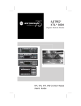
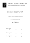
Figure 5-1 shows the block diagram for a standard
guided missile SA device
[McVay,
1987].
The
interruptors
have mechanical and direct locking as required by MIL-STD1316C.
28
Inte rruptor
Mover
Intej rruptor
Interruptor
Locking
Mechanism
^^^
Mover
'ower
Energy
Interruptor
Firing
Capacitor
;onditioning
System
Energy
Interruptor
Energy
Source
f
Fuze
Logic
^jswitch
—1
1
r
Detonator
Noninterrupted Explosive Train SA Device
Figure 5-1.
C
.
SYSTEM
I
OPERATION
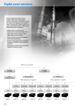
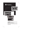
Figure 5-2 is a system flowchart for the SA device under
analysis.
[Hayward,
we modified the original Hayward
In Figure 5-3,
software
flowchart
port
control
1987]
by
interface
identifiers The
.
firing
abstracting the
and
hardware/software
removing the
sequence
in
assembler
Figures
5-2
originates with the missile on an aircraft rack.
to launch
(ITL)
thermal battery,
computer,
builds
a
[1987]
and
code
5-3
An intent
signal initiates a sequence which fires the
charges the firing capacitor,
and unlocks the
SA device.
The
powers the
software then
preset safe separation distance lookup table for
current distance comparisons.
29
Missile on
fl/C
Rock
H/C signolslntent to
Launch
Firing Capacitor
(ITL)
Charged
I
unlocks SR,
Fires thermal battery,
Poiuers Computer
ITL
v
Rocket Motor Fires
ir
Launch
i r
4* G Boost
1
r
Software computes
Safe Separation Distance
1 r
SR Deuice Rrms
1
r
SR Locked
in
Rrm
1 r
Target Detection
I
^
Detonation
Figure 5-2
.
SA Device System Flowchart
After missile launch, the software uses inputs from an
analog to
digital
converter
(ADC)
and
a
timing
loop
to
compute current separation distances from the launch vehicle.
30
tnablo
»olenoi(J
Buna lookup
UDIO
X
imtioiiz* lookup loDie pointer
itert at lout
lookup toon
pointer
Enable
H/0 Conuerter
*
Irue
(noble R/D
Conuorlor
Input Current
Deceleration biei
Input Curront
Diteble
R'D Conuerter
flmlcraimn
update
Oitobie
Initial
Deceleration
H/D Conuerter
i
Input
Hccoiarotlon biat
Update Currant
ueioclty
i
Update separation
dutanca
Increment
lookup labia
Pointer
loggia
Solenoid left
IKoit
200
lor Soienoid
looole
to
in
It
true
Figure 5-3.
SA Device Software Flowchart
31
A minimum 4G boost is required before the program will
compare the calculated separation distance with the lookup
If the calculated value exceeds the current
table values.
tabular value, the lookup table entry pointer is advanced to
the
next
table
value.
software
The
then
commands
the
lock
mechanism
rotating the interruptor by a one-third increment.
Next, the
solenoid to
resulting
toggle,
software enters
in
a
ball
delay loop to provide sufficient time for
a
the solenoid to toggle.
The program then loops back, updates
the acceleration bias from the ADC output,
and starts over.
If the calculated value is less than the lookup table entry,
the software delays,
tance,
updates the calculated separation dis-
and conducts a second comparison.
distance
is
then
exceeded,
the
solenoid
If the tabular
is
toggled
as
previously described. Three solenoid toggles are required to
remove the interruptor.
In
addition,
the warhead can not
detonate unless the SA device is unlocked (which occurs after
ITL is signalled)
and the firing capacitor is charged.
32
MODELING AND ANALYSIS
VI.
A.
PROBLEMS
IN
SOFTWARE
METHODOLOGY
SYSTEM MODELING
The major problem in software system modeling is that the
model must be sufficiently accurate and detailed to provide
meaningful
safety
analysis
incorporate the software flowchart,
features,
Modeling should be
must
important environmental
the nature of system components,
conditions.
model
The
results.
and any initial
process of cooperation and
a
continuous feedback between the designer and the modeler.
Since the modeling process is difficult, nonessential details
should
be
omitted.
determine detail
Although
significance,
it
is
difficult
quite
the reduction of the system
scope is important for minimizing required modeling time.
any system facet's significance is unknown,
incorporate
it
into the
to
model.
The
it
is
If
best to
system designer must
provide feedback to the modeler to ensure
a
sufficiently
accurate model.
Hayward [1987] presented a methodology for building Petri
net models of real-time,
software-controlled systems.
He
provides detailed instructions for translation of software
flowcharts to Petri nets and discusses a methodology for
combining hardware and software
single Petri net model.
33
system
functions
into
a
While preparing the Hayward system model for automated
analysis, we discovered several modeling flaws and corrected
them.
B
.
Our work reflects those improvements.
A BOTTOM-UP APPROACH
Our initial research plan was to familiarize ourselves
with the the fuzing system, convert the Hayward [1987] model
to entry text file,
and conduct P-NUT aided automated safety
Although the Hayward [1987] model was an excellent
analysis.
first attempt,
serious shortcomings were soon discovered in
Following this discovery, we
the system component models.
expanded our plan to
include
corrections to the Hayward
model
After familiarization with the software and components of
the
safety
arming
device,
we
accepted the basic
system
framework and began at the module level of the Hayward model.
We
examined the
modules
and
functionality of the existing Petri net
compared this
component behaviors.
with
our
knowledge
of
actual
This is not the method we recommend for
conducting first-time modeling and analysis of a system.
As
stated in Hayward [1987], the initial modeling process should
be a top-down approach,
flowcharts
and
beginning with system and software
interfaces,
and abstracting
out
internal
component functions. The final step prior to safety analysis
should be component modeling and verification.
Since we were
given an essentially correct system framework, we began our
34
work from the bottom up. We redefined component interfaces,
created the
internal
component Petri
nets,
and verified
(ITL)
sensor first.
correctness with P-NUT.
1
.
ITL
Sensor Module
We studied the Intent To Launch
The Hayward model is shown in Figure 6-1.
tl
4>
T
0n
•^
t2
Figure 6-1.
Hayward ITL Sensor Model
Figure 6-1 effectively models
a
two-state device, but
an ITL sensor must do more than simply toggle.
The sensor
must have a means for outputting its current state.
In the
SA device under analysis, the software program checks the ITL
sensor to
follow.
determine which of two
control
flow paths
to
The model in Figure 6-1 has no mechanism to allow
NonDestructive Readout (NDRO) of its stored state and clearly
needed this addition.
35
component
A
model
must
reflect
system
interface
requirements and accurately represent behavior of the actual
device.
As
initial
an
step,
functionality
component
interfaces.
and
the modeler
document
should analyze
required
system
He must then ensure that the model accurately
represents all significant aspects of function and control
flow.
After adding NDRO capability to the ITL sensor, we
realized that
requires
a
component
a
proper model
system lock.
receives
a
The
command,
of
a
multifunction
lock ensures
it
prevents
that
new
device
once the
command
processing until completion of the original input command.
In the ITL sensor,
this is critical.
Without a system lock,
NDRO could occur while the device was toggling and result in
erroneous ITL indication.
The diagram for the revised ITL
sensor is shown in Figure 6-2.
To increase readability and connectivity of the Petri
net diagram, we recommend a standard input/output convention
for all
system modules.
This
convention is reflected in
Figure 6-2 and consists of distinctly shaded input and output
places.
36
ITL
ITL
Toggle
tt
ITL
NDRO
Input
Received
Sensor
Read
ITL
t2
Ready
Op-
mi
ITL
Toggle
Enabled
Status
o
t3
ITL Is
t5
true
no
ITL
-iM
t6
ITL
3
Figure 6-2
In
the
complete
with
raise
Refined ITL Sensor Model
.
system net,
modules should be abstracted.
"black-boxes"
Is
only
the
contents
of
the
The modules are depicted as
interface
places
shown.
This
convention encourages regular component and system modeling.
37
Regularity is important due to the nontrivial nature of realtime systems.
large systems projects,
In
employed.
In
these projects,
it
modeling teams could be
is
both appropriate and
necessary to apply software engineering methods for module
specification, namely clearly defined and consistent module
interfaces.
Beginning with the ITL sensor module in Figure 6-2, we
adapted
the
electrical
engineering
wiring
schematic
convention to our modeling of intersecting Petri net arcs.
Transitions t3, t4, t5, and t6 create and place tokens in the
system-ready
place.
conserve
To
space
improve
and
readability, we use intersections with nodes to denote common
arcs between several transitions and a single place.
It
is
important to note that this convention is inappropriate for
representing
transition,
arcs
as
between multiple
this
would
violate
places
and
standard
single
a
Petri
net
Additionally, the number of transition inputs
conventions.
and outputs must be readily apparent to an analyst without
requiring
a
count of scattered intersecting lines.
Creation of the ITL sensor in Figure 6-2 was
step process.
a
multi-
We began with the Hayward model of a two-state
device and through a trial-and-error approach developed the
model with NDRO capability.
38
The fundamental idea of a nondestructive read is to
allow the sensor to output its state without changing that
state. In Petri net terminology, the device must output state
indication and simultaneously return to the marking held
prior to the commanded read.
Since no modeling of control or
information flow is possible without token consumption and
creation,
the modeler must be innovative but should resist
the temptation to build a baroque structure.
The addition of
places in a net can significantly add to reachability state
space size and correspondingly increase analysis difficulty.
(There are exceptions to this statement,
of interlocks,
such as in the use
which actually restrict the reachable state
space.
After creating the ITL sensor model, we converted the
Petri
net to a textual file, built a reachability graph of
the system using P-NUT, and analyzed the reachable states by
printing the graph.
The textual Petri net for the ITL sensor
model is shown in Figure 6-3.
To
reduce
descriptions.
file
size,
we
shortened
most
place
We follow this procedure throughout our work.
In more complicated Petri nets,
ten or more marked places per
state are common, often filling several output lines for each
state description.
name abbreviations.
Modelers must be uniform selecting place
The pnl tool
39
is
extremely useful
for
uncovering notational discrepancies and should be used prior
to translating all text files to internal P-NUT format.
tl: ITL_toggl_rcvd, ITL_snsr_rdy ->ITL_toggl_enabld
t2: ITL_NDRO_inpt, ITL_snsr_rdy -> rd_ITL_status
t3
ITL_toggl_enabld, ITL -> no_ITL, ITL_snsr_rdy
t4: ITL_toggl_enabld, no_ITL -> ITL, ITL_snsr_rdy
t5: rd_ITL_status, ITL -> ITL_is_true, ITL, ITL_snsr_rdy
t6: rd_ITL_status,no_ITL -> ITL_is_false,no_ITL, ITL_snsr_rdy
/* following code is for test looping purposes only */
ITL_is_true -> ITL_toggl_rcvd
t7
t8: ITL_is_true -> ITL_NDRO_inpt
t9: ITL_is_false -> ITL_toggl_rcvd
tlO: ITL_is_false -> ITL_NDRO_inpt
:
<ITL_NDRO_inpt, no_ITL, ITL_snsr_rdy>
Textual ITL Sensor Petri Net
Figure 6-3.
To ensure all
reachable states were identified,
we
added a looping structure at the end of the input text file.
These added transitions simply feed the output back into all
possible input places,
possible.
ensuring all inputs and outputs are
This procedure
is
recommended for testing any
module that has multiple inputs and outputs.
could be
achieved by creating
reachability graph
for
a
separate
each possible
The same effect
text
initial
file
and
condition,
however our approach accomplishes this with one text file and
reachability graph. We translated the ITL sensor textual net
using transl, built the reachability graph with the RGB, and
used RGP to print it in readable form. This reachability graph
is shown in Figure 6-4. The ITL sensor graph and state space
40
were sufficiently small to allow verification by hand tracing
and inspection, thus the RGA was not used.
0- >l->2- ->o
1
+->3->4 ->5
ITL snsr rdy,ITL NDRO inpt, no ITL
rd ITL status, no ITL
ITL snsr rdy,no CTL, ITL is fal se
ITL toggl rcvd, ITL snsr rdy ,no ITL
ITL toggl enabld, no ITL
ITL snsr rdy, ITL
0.
1.
2.
3.
4.
5.
'.
ITL Sensor Reachability Graph/State
Figure 6-4.
2
.
Analog to Digital
The
Hayward
Converter
[1987]
model
for
(ADC)
ADC,
Space
Model
Solenoid,
Solenoid Control devices is shown in Figure 6-5.
enable
tl
Off
t2
disable
Figure 6-5.
processed
Hayward Two-State Device Model With
Response
41
and
Unfortunately the model in Figure 6-5 inadequately
Our methodology for modeling
represents the actual devices.
the ADC follows.
First, we analyzed the function of the ADC in our SA
device.
The
converts
ADC
accelerometers) to
a
an
analog
input
signal
digital acceleration output.
(from
It should
provide digital acceleration information when enabled and no
output when disabled.
The ADC has two interfaces with the
overall SA system.
outputs digital acceleration values
It
and provides feedback that it has been enabled or disabled.
To represent
control flow,
we created a model that
could be enabled or disabled and provide necessary feedback
following command processing.
Our approach was limited in
that we did not attempt to model the information flow of the
module.
We assumed that
if the ADC was
enabled it would
provide correct acceleration information, and if disabled it
would not.
the
This significant assumption was made to reduce
scope of the model
in view
of time
constraints.
It
should not adversely affect the credibility of the analysis.
If the ADC malfunctioned and provided incorrect acceleration
in excess of the actual value,
be
overestimated and
could
the separation distance would
result
separation distance at detonation.
in
insufficient
safe
This is an obvious result
and there is little need to expend the extra effort and time
required
to
model
it.
To
42
ascertain
correctness
and
reliability
software
should
hardware
of
system
be
component's
environment.
analysis.
"design
for
components
safety"
within
behavior
safety
The
or
not
is
goal
analyst's
the
context
the
the
effect
of
the
in
concern
of
the
system
Figure 6-6 shows the refined ADC model.
Unable
DISABLE
INPUT
Coimmand
Rec
•ceiued
U
\J
\f
01 •able
INPUT
sK
^*v
(
<r
\
I
/V_y\
Enable
\
/v_x"
Command
Receiued
\?
KJ.
»
System
System
Ready
u
H
GkJ
System
Disabled
Enabled
OUTPUT
Figure 6-6.
Refined Analog to Digital Converter
Model
43
(ADC^
In Figure
6-6,
the system lock,
ADC-Ready,
reflects
device inability to process simultaneous enable and disable
commands
toggle.
structure
control
The ADC
more
is
than
simple
a
must differentiate between enable and disable
It
commands and allow redundant command processing.
modeled by adding transitions t2 and t4
or disable commands are received,
This was
If redundant enable
.
the model will not change
states.
It will,
however, process the redundant command and
signify
that
has
it
done
so.
This
component with on and off switches.
pressed
down.
can
a
second time,
or
disable
redundant
purposes.
device.
analogous
to
a
on switch is
If the
it does not cause the system to shut
If a real-time system has multiple components which
enable
allows
is
It
is
a
critical
enable/disable
our
component,
commands
it
for
normally
insurance
assumption that the ADC is
If redundant commands were not allowed,
such a
this could
easily be modeled by eliminating the redundant transition's
ability to deposit a token in the command-processed place.
To accomplish this,
simply remove the appropriate arcs. This
would eliminate redundant command feedback.
Following model creation, we again turned to P-NUT to
verify
correctness.
We
followed the
analysis of the ITL sensor and produced
reachability graph and state space.
44
same
a
steps
as
in
printout of the
The textual file for the
ADC module
contained in Figure
is
while Figure
6-7,
depicts the resulting Petri net reachability graph.
a
small
and
listing
analysis
began
with
6-8
This was
manual
state
We examined all reachable states and validated
examination.
As a final check, we briefly analyzed the module
the module.
with the RGA.
:t0
:tl
:t2
:t3
:t4
:t5
:t6
disable_input, system_ready -> disable_cmd_received
enable_input, system_ready -> enable_cmd_received
disable_cmd_received, system_disabled -> system_disabled,
cmd_jprocessed
enable_cmd_received, system_disabled -> system_enabled,
cmd_processed
enable_cmd_received, system_enabled -> system_enabled,
cmd_processed
disable_cmd_received, system_enabled -> system_disabled,
cmd_processed
cmd_processed -> output, system_ready
/* the following code is for test loop purposes only */
:t7:
:t8:
output -> enable_input
output -> disable_input
<disable_input, system_enabled, system_ready>
/* initial markings */
Textual Version of ADC Petri Net
Figure 6-7.
Could
enabled?
We
model
this
be
simultaneously
knew this to be
impossible
inspection and verified it with the RGA.
this
question
[ADC_enabld(s)
to
=
1
RGA
language
45
from our
and
state
The translation of
exists
is
and ADC_disabld(s)
disabled
=
1]
.
s
in
S
0->l->2->3->5->7->2
I
+->4->6->8->9->0
I
+->10->ll->8
disable_input, system_ready, system_enabled
disable_cmd_received, system_enabled
2. system_disabled, cmd_processed
system_ready system_disabled, output
3
4
system_ready, enable_input, system_disabled
5
disable_input, system_ready, system_disabled
6. enable_cmd_received, system_disabled
7
disable_cmd_received, system_disabled
8. cmd_processed, system_enabled
system_ready system_enabled, output
9
10
system_ready, enable_input, system_enabled
11. enable cmd received, system enabled
.
1
,
,
Reachability Graph for ADC Module
Figure 6-8.
The question is interpreted by RGA as:
reachable
state
which there
in
is
Is there any
token
one
in
the ADC
enabled place and one token in the ADC disabled place?
response was false.
set
variable
We then asked the same question using a
assignment
and
assigned
the
malfunctionl to this particular malfunction.
for
this
question
ADC_enabld(s)
=
RGA
is:
1
interpreted this as:
and
malfuntionl
ADC_disabld
:=
(s)
variable
name
The RGA input
{s
=
in
1}.
S
|
RGA
Evaluate all elements of the set of
reachable states in which both of listed places contain one
token and assign this set to the variable malfunctionl.
RGA
responded with a set of empty curly braces, "{}"/ signifying
46
that malfunctionl was currently of type set and had the value
of
null.
session,
redisplay the variable value
To
later
in
the
malfunctionl,
we entered the variable identifier,
and RGA again responded with the empty set.
deadlocks
We then tested for system deadlocks:
{s
in S
= 0}.
|nsucc(s)
nsucc(s)
is
a
predefined integer
expression that returns the number of successor states to
specified state
:=
a
The above expression is interpreted by
s.
Assign to the variable deadlocks all elements of the
RGA as:
subset of reachable states that have no possible successor
The RGA responded with the empty or null set.
states.
3
.
Solenoid
We
next
Model
turned
attention
our
modeling the SA solenoid.
status
left
determines
the
and
of
The solenoid is a two-state device
with enable/disable and NDRO capabilities.
to
problem
the
to
status
launched
right.
missile
When
has
Two states refer
the
SA
achieved
software
a
proper
increment of safe separation distance, it checks the solenoid
status
The solenoid toggles,
a
and commands the appropriate toggle.
(right or left)
ball
and
increment.
removed.
move
causing the ball lock mechanism to drop
the
fuze
interruptor
Following three toggles,
The
solenoid system input
enable/disable, read,
sensor and ADC,
by
the
47
one-third
interruptor
commands
and toggle left/right.
the system accepts
a
consist
is
of
As in the ITL
only one command at a
If a second command is received prior to completion of
time.
the first,
it is ignored.
Hayward [1987] modeled the solenoid by creating three
solenoid control,
separate modules:
status toggler.
were
solenoid,
and solenoid
These three independent Petri net models
intended to model
a
single
system
component.
The
solenoid control and solenoid modules were replicas of the
The solenoid control module
two-state device in Figure 6-3.
modeled enable/disable
functions
solenoid module
and the
modeled the left/right toggle functions.
The third module
represented software status indication of the solenoid but
toggled independently of the solenoid module.
Since the SA device was never actually constructed,
the software prototype required a method to
toggle position.
bit
in
a
It
simulate the
accomplished this by toggling
memory register.
The
a
status
Hayward solenoid status
toggler is the model of this register function.
We
attempted to
analyze
software controlled SA device.
system
with
all
designed
safety
of
the
completed
Accordingly, we modeled the
software/hardware
interfaces
incorporated in a single full-function module.
Creation
revisions
of
the
and two weeks
solenoid model
of
required
intensive effort.
The basic
functions were defined and all interfaces specified.
attempted to abstract another level of the device.
48
several
We then
Since the
solenoid performed three separate functions,
project
functionally
NDRO,
into
we
left/right
toggle,
and
Rather than attempt module
enable/disable capabilities.
creation in one step,
we broke the
combined the ADC "smart" toggle
function and the ITL sensor's NDRO capability as our first
step.
The resulting module is shown in Figure 6-9.
Actuate
Disable
Input
NORO
Enable
Input
System
Ready
IW.
t
if
16
©
f\J
Read
Enabledl
Disabled
Status
\7
Enabled
Status
t8
i
Figure 6-9.
Output
ITL Sensor and ADC Modules
49
Combined
We then converted the the enable/disable toggle in
Figure 6-9 to a left/right function and added another twostate module for enable/disable capability.
We added a model
feature which would disallow any accumulation of input place
Token accumulation in the model could result from
tokens.
multiple input commands.
Since Petri net transitions fire
nondeterministically, these input commands might be handled
out of order.
The actual solenoid has no memory and can not
respond to commands received while "in process".
net model terminology,
consumed.
In Petri
the additional input tokens must be
Figure 6-10 shows the final solenoid model. The
solenoid model in Figure 6-10 has three fundamental operating
is
the
System_ready
ready (enabled), disabled, or in use.
states:
equivalent of the system_ready places of the
sensor and ADC models in Figures 6-2 and 6-6.
A token in
this place indicates the solenoid is enabled (has power)
is
ready
to
process
solenoid__in_use
input
place
commands.
indicates
that
A
the
ITL
token
in
and
the
solenoid
is
processing an input and will not accept further inputs until
processing is complete.
A marking of the system-disabled
place represents power is off and no processing is possible.
50
~rt
TX
r -
RF
m 3
c a.
1
'VJT
z c
±rj-
z s
• l*
fr
T
~~
<3
t, ,t
SB
c
w
BE
IX
Z
K>
K>
Figure 6-10.
tti;
O^
jMrt
Final Solenoid Model
51
£
=>
The token accumulation problem described above
solved by the addition of token consumption loops.
is
If the
transitions tl3 to tl7
solenoid in Figure 6-10 is in use,
ensure consumption of all incoming tokens without altering
the
command
process.
in
If
solenoid
the
is
disabled,
transitions tl8 to t21 ensure that only an enable command
will be processed.
All other input tokens will be consumed
and the system will remain disabled.
After
solenoid token
the
scheme
was
we did not "backfit" this feature to the ITL
incorporated,
sensor and ADC Petri net models.
constraints.
consumption
This was solely due to time
Our goal was to demonstrate procedure validity
for preventing input token accumulation
in
any "no-input-
memory" device.
In Figure
6-10,
no input transitions can fire unless
there is an enabling token in the system_ready place.
When
an input transition fires, this token is consumed and a token
is created and placed in the in_use place.
The method for returning the solenoid model to ready
state after processing is shown in all the output
transitions of Figure 6-10.
place
outside
the
module
firing
Any transition that fires to a
requires
an
input
token
from
thein_use place. When an output transition fires, a token is
created and placed in the system ready place.
52
A
enable/disable
left/right
toggle
toggle
6-10.
Figure
in
6-6
Figure
in
between
exists
difference
major
and
solenoid
the
ADC
The
ADC
the
must
treat
redundant enable/disable commands no differently than genuine
(In the solenoid
toggles in terms of feedback to the system.
system-ready/disabled toggle, redundant commands are allowed
and reflect this philosophy.)
Redundant solenoid left/right
toggles are not handled in the same manner.
solenoid received
redundant
a
toggle
If the actual
and provided
input
feedback, no toggle or resulting movement by the interruptor
would occur, but system software would erroneously proceed as
if these required events had taken place.
For this reason,
redundant solenoid toggle transition firings do not create a
token in the toggled place.
Following model creation, we converted the Petri net
We translated the
to textual form and input it into P-NUT.
file,
constructed
the
reachability
graph,
printed
the
graph/state space, and analyzed the graph on RGA.
Although
larger than the ADC
solenoid
and ITL
sensor graphs,
the
reachable state listing and graph still permitted manual
state
inspection
and graph
tracing.
The
text
file
and
reachability graph are contained in Appendices D and E.
The final solenoid model in Figure 6-10 reflects a
major
change
from
our
original
module.
discovered during solenoid RGA analysis.
53
The
error was
We asked for the
set
system deadlock
of
states
surprised when RGA responded with
enhance
analysis
prevent
and
Chapter VI)
(see
a
two-state
deadlocks,
and were
set.
had
we
To
added
transitions to return output tokens back to any input place.
One
state had markings
deadlock
left_toggle_received,
in
toggle_is_left, and in_use, while the other deadlock was the
equivalent
redundant
right
toggle
Redundant
state.
left/right toggle transitions, t2 and t4, originally had not
required an enabling token from in_use or an output arc back
to system_ready
the
.
This resulted in the model deadlocking in
whenever
condition
in_use
a
redundant
This was clearly not our intention.
received.
wanted the
solenoid model
to
toggle
was
Although we
withhold redundant
toggle
feedback, we never intended it to result in module deadlock.
system view,
this was equivalent to disabling the
solenoid permanently.
The correction was easily made and the
From
a
final text input version is shown in Appendix D.
contains
the
resulting
reachability
Appendix E
graph printout
and
reachable state descriptions.
We input the corrected model net to RGA.
We again
asked for the set of deadlocked states and RGA responded with
the null set.
tokens.
We then tested for possible accumulation of
More than one token in a given place would signify
that the model had failed to prevent command inputs while in
use.
We changed the input text file
54
(Appendix
D)
initial
conditions by adding a second token to the toggle_left_input
A new internal net was created and
place.
graph built.
analyzed
then
excesstokens
The new reachability graph
:=
in
{s
S
tokens
|
containing at
evaluated as the
least
one token
>=
(s)
(s)
integer number of total tokens present
is
expression
input
The
RGA.
on
The predefined RGA expression tokens
marked(s)
reachability
This procedure is required every time changes
are made to the input text file.
was
a
marked(s)}.
is evaluated as the
in
given state.
a
integer number
in
a
was
of
given state.
places
If the
number of tokens ever exceeds the number of marked places in
any state,
it
indicates token accumulation in at least one
place.
When RGA evaluates the expression,
subset
of
reachable
Boolean condition.
which
states
returns the
it
satisfy
specified
the
As in previous examples,
showstate
(s)
function is then used to display individual place markings
within
and
a
given state.
returned
a
RGA evaluated our entered expression
set
states
of
in
which
only
toggle_left_input place contained more than one token.
this was our initial condition,
it
the
As
validated our multiple
input token prevention scheme.
We returned to analysis of the model with single token
initial markings and asked if it were possible to have the
solenoid
simultaneously
ready
disabled, or in use and ready.
55
and
disabled,
in
use
and
If these supposedly mutually
exclusive markings were possible it would represent a serious
We labeled this subset identifier as errorl
design flaw.
Since we had shown that there was never more than one token
in any place, we were able to simplify our input expression.
The RGA input for this question was:
(system_ready
(s
(in_use(s)
system_disabled (s)
+
system_ready (s)
system__disabled
+
)
errorl
>
1)
:=
>
(s)
or
in S
s
{
|
or
1)
(in_use(s)
+
RGA evaluated the expression and
> 1)}.
Since we had proven a maximum of one
returned the null set.
token in each marked place, arithmetically adding the place
values in the first half of the Boolean expression was simply
a
shorthand expression for those states in which any were
If any of the places could have contained more than
marked.
one token,
expression
this expression could not be used.
would
(system_ready
(s)
(system_ready (s)
and
then
=1
=1
errorl
be
{s
system_disabled
and
and in_use(s)
system_disabled(s)
:=
=1)
or
The proper
in
(s)
S
|
or
=1)
=1
(in_use(s)
=1)}.
We performed a similar test for the erroneous state
resulting from any two of the following places simultaneously
marked:
re
ad_e n ab 1 ed
right_toggle_received,
expression
was
read_enabled
(
s
1 e f
system__ready,
entered
system_disabled.
error2
as
:=
{s
lef t_toggle_received
+
right_toggle_received
t_t ogg 1 e_r e ce i ved
(
s
)
56
+
system_ready
This
in
(
(
S
|
+
s
s
,
)
+
>
system_disabled(s)
RGA again responded with the
1}.
null set.
To prove that the module returned to a ready state
following output,
asked RGA to return the set
we
of all
states in which any of the output status or toggled places
We named
was marked simultaneously with the in-use place.
the subset identifier output_error
question
this
output_error
was
(status_is_left(s)
toggled_output
=
1)
.
{s
in
=
1)
and
(
S
s
|
+
)
(in_use(s)
RGA evaluated the expression and returned the null
This
set.
:=
status_is_r ight
+
en_dis_output
+
(s)
The RGA expression of
.
final
check
To confirm our assessment,
validation.
correctness
module
completed
we hand-traced the
reachability graph and examined all possible state sequences.
4
.
System Petri Net Model
The
Following Solenoid testing,
[1987]
we refined the Hayward
overall system model.
The original Hayward model specified no requirement
for missile release prior to the occurrence of a 4G boost.
The attainment of this great an acceleration is impossible
with
the
missile
transitions
necessary
til
the
on
and
sequence
tl2,
of
rack.
in
rack
occurring.
57
The
Figure
release
interlock
6-11,
prior
between
reflects
to
the
the
boost
4+G
boost
occurred
missile
released
Figure
In
conversation with NWC China Lake,
phone
a
Modeled 4+G Boost Interlock
6-11.
fuzing system designer, Mr. Steve Rohde, specified
4G
acceleration
boost
as
precondition
a
to
a
the
minimum
separation
This precondition prevents any
distance update calculation.
toggling of the solenoid or interruptor movement without the
required accelerative boost.
This feature is modeled in our
system Petri
F)
occurred
a
(Appendix
net
by
making the
required input place to the update
distance transition,
t59.
4+G
boost
separation
4+G boost occurred must be an
output place of t59 to ensure accurate reflection that this
precondition
has
been met
in
any
subsequent
separation
updates
In Figure
1
and
2
6-12,
ITL locks
1
and
2
and no-ITL locks
were added after conversion of the net to P-NUT
textual input form.
While entering the net,
we discovered
that there was no current method to describe and maintain
which of several paths was being taken on ADC entry and exit.
In the system control
flow,
the ADC is enabled following a
58
read of ITL status.
In Figure 6-11,
if ITL is true,
control
and if false, the right path is
flow follows the left path,
traversed.
If
ITL
acceleration
disabled.
is
is
true,
input
the
ADC
the
software,
to
is
enabled,
and
the
current
ADC
is
After the ADC is disabled, control and information
flow continue along the ITL path toward possible detonation.
If
ITL
the
false,
is
ADC
is
enabled,
acceleration bias is sent to the software,
disabled.
current
and the ADC is
The control and information flow then updates the
acceleration and loops back to recheck ITL status.
Although there are four ADC instantiations in the net,
the SA system contains only one physical device.
The ADC is
enabled/ disabled via one set of input places and feedback to
the system is via a single set of output places.
Petri
net
is
nondeterministic,
there must be
methodology to ensure correct path maintenance.
a
Since a
modeling
The method
we devised is to place system locks at module entry and exit
points
whenever
there
was
a
path
choice.
This
lock
guaranteed that only the correct transition would be enabled
upon module output.
Figure 6-12 shows the ADC portion of the
final system net with path locks in place.
59
no-ITL
lock 1
input current
Input current
acceleration
acceleration
bias
acceleration/
V^
Inputted
A
Obias
inputted
)
disable
t54
RDC
t55_}^_ disable
" RDC
RDC
disable
input
(
t45
-
t5
t45
-
t5l)
RDC
OUTPUT
156
Input
t57
6
acceleration
RDC
OUTPUT
no-ITL
lock 2
update
initial
acceleration
bias
Figure 6-12.
Portion of Final Petri Net Model With
Path. L££X&
Since three solenoid toggles will result in removing
the interruptor, we have used the model proposed in Peterson
60
[1981]
to count the three required software commanded toggles
(iteration
counter).
counter
This
models
the
system
software trap and halts the program following the third
software-commanded solenoid toggle.
presence
of
two
tokens
Figure
counter
the
in
In
6-13,
reflects
the
first
Accordingly,
iteration completion prior to transition t79.
this counter will enable t79 for only two firings.
await
sep
distance
check
check
sep
distance
iteration
counter
Figure 6-13.
There
is
an
Petri Net Model of a Counter
aspect
of
the
actual
system that we
intentionally omitted to reduce model scope and complexity.
Actual system software enables the solenoid prior to,
disables
it
following,
each read/toggle.
We
and
enable the
solenoid initially and do not disable it on each iteration.
This
should not
affect
model
validity,
since
we
proved
earlier that the disabled solenoid model could neither toggle
nor output status.
61
5
P-NUT Aided Safety Analysis
.
System Model
of
We converted the graphical net to P-NUT text
translated
format,
printed the
resulting
reachability graph,
built the
it,
reachability graph to
RGP
contained
output
the
of
output
file.
The
over
13,000
states
and
examination
forced
and
graph
reachability
reliance
total
and
an
required over five megabytes of memory storage.
magnitude
file
The sheer
precluded
on
manual
automated RGA
The textual version of the system Petri net
analysis.
is
shown in Appendix G.
Due to time constraints,
analysis
to
reachability
of
we limited our RGA safety
major
hazardous
and
mishap
states
To determine the possibility of missile detonation
while attached to aircraft wing we entered:
in
S
missl_on_rack
|
(s)
=
RGA responded with the null
1
detonation
and
set,
hazardl :=
meaning
it
(s)
was
=
{
s
1}.
not
a
reachable state of our model.
To determine if detonation could occur when ITL was
false,
we entered the expression:
no_ITL(s)
=
and detonation (s)
hazard2
:=
=
RGA
1]
.
{
s
in S
|
responded
with the null set.
We
next
determined the possibility
occurring without a minimum 4G boost.
62
of
detonation
We entered hazard3 :=
{
1},
s
in
S
|
fourG_bst_occrrd(s)
=
and detonation
(s)
=
and RGA returned the null set.
As a
final question,
we
asked if detonation could
occur if no power was routed to the computer.
hazard4
:=
detonation (s)
{
=1}
s
in
S
|
cmptr_off
The expression
(s)
=
also resulted in the null set.
63
1
and
VII.
A.
RESULTS
CONCLUSIONS
AND
RESULTS
thesis has proposed a methodology for Petri net
This
modeling
automated
and
concurrent system.
of
a
real-time
The sample system is a proposed air-to-
guided missile
air
analysis
safety
and Arming
Safety
(SA)
device.
The
methodologies for initial modeling and safety analysis of
representative
this
real-time
system
originally presented in Hayward
methodology
were
Our goal was to
[1987].
refine the modeling methodology presented by Hayward and to
demonstrate the methodology
for,
and the
feasibility of,
automating the safety analysis.
We
introduced
reachability theory.
the
Petri
Net
software
safety,
Petri
nets,
and
We demonstrated steps required to use
Utility
Tools
(P-NUT)
and
discussed the
extensibility of the P-NUT Reachability Graph Analyzer (RGA)
We next discussed P-NUT potential
for automating detailed
safety analysis.
We
have
presented
a
methodology
analysis using Petri net modeling.
for
system
safety
Using this methodology,
we initially analyzed all aspects of system functionality and
documented internal
interfaces.
We
then
abstracted the
individual components and constructed Petri net component
models based on a thorough study of their operation, control
64
We converted each Petri net
and system interfaces.
flow,
model to textual form,
entered it into P-NUT,
model design using P-NUT automated tools.
and validated
After all system
component models were verified, we examined the system Petri
net,
as presented in Hayward
[1987]
After comparing the
.
control
flow of the net with our understanding of actual
system
operation,
we
discussed
the
basis
for
several
refinements and demonstrated use of P-NUT to construct the
reachability
expressions
hazardous
graph.
Function
and predefined
state
use
functions
reachability
concluded by demonstrating,
and
were
of
examination
for
then
various
presented.
RGA
of
We
from a preliminary standpoint,
how to determine system safety.
B.
CONCLUSIONS
As previously stated,
our initial research goal was the
automated analysis of a preexisting real-time system Petri
net
model.
[Hayward
Unfortunately,
1987]
was
the preexisting
incomplete,
requiring
system model
remodeling
of
components and refinement of the system Petri net structure.
We essentially
employed
a
accepted the Hayward system framework and
bottom-up approach.
We
redesigned component
interfaces and internals and verified correctness on the
module scale prior to refining the system net structure and
conducting automated safety analysis.
65
The recommended chronology
automated
analysis
safety
for Petri net modeling and
A brief
follows.
summary
is
contained in Appendix H.
Initially,
modeler/analyst
the
should
system
study
function and the designer's description of possible mishap or
hazardous
system
He must
states.
include
to
then reduce the
significant
only
scope
of the
and
details
aspects
Although this is possibly the
pertinent to stated hazards.
most difficult step in the entire process, it is critical to
reducing scope and complexity of the resulting net.
very
nature
mishaps,
of
it
extremely
is
By the
difficult
to
ascertain the relative import of individual components or
processes.
features
It
of
is
the
therefore imperative to incorporate any
system that
hazardous or mishap states.
designer
is
to
to
reaching
it is possible to refine the
Continuous
critical
contribute
If more model detail is desired
after initial net construction,
original Petri net.
may
feedback from the system
accurate
modeling
and
safety
analysis
The modeler must
thoroughly.
He
study system and software
must
document
all
flowcharts
software/hardware
interfaces and incorporate the flowcharts into a single Petri
net system description.
Component internals should initially
be abstracted with "black-box" descriptions and incorporate
only required system interfaces.
66
Multiple instantiations of
a
component should be presented in the system net as separate
"black-box" descriptions.
After the
designer,
framework
is
complete
and approved by
the
system component functionality should be studied
and modeled.
As in the system framework approach,
one must
incorporate only the desired aspects of component behavior
and attempt to further divide the individual components into
submodules,
i.e.,
NDRO module,
toggle modules,
An
etc.
example of this second level of abstraction is found in our
solenoid module
basically
a
(Appendix
C)
This
.
Petri
combination of three two-state
net
model
is
devices with
appropriate internal interfacing.
As each component model
is
completed,
used to verify desired behavior.
P-NUT should be
Proving component function
and interface correctness on the module level permits easy
and accurate incorporation into the system net.
After completing the initial system model, P-NUT should
be
employed to
construct
the
reachability
graph.
RGA
automated safety analysis is then possible and can verify
desired system behavior and safety.
Manual construction of
a
13,000-state reachability graph
would be an arduous, lengthy, and error-prone process.
can construct this size graph on a Sun
two minutes of CPU time.
67
2
P-NUT
computer in under
P-NUT is an extremely powerful suite of tools for Petri
One of the major drawbacks of the Petri net
net analysis.
safety analysis methods cited in Leveson and Stolzy [1987] is
the
difficulty
of
constructing
reachability
complex concurrent-system Petri nets.
graphs
for
The Reachability Graph
Builder eliminates this problem, while the Reachability Graph
Analyzer permits detailed analysis of the graph and reachable
state space.
The extensibility of the RGA language makes it
extremely powerful and allows safety analysts to create and
use predefined function libraries.
We have shown how RGA
quickly evaluates sensible and important safety questions.
Answering these questions for complex reachability graphs
would be extremely difficult,
if not
impossible,
based on
manual construction and analysis.
While
conducting
our
research,
we
came
to
fully
appreciate the feasibility and suitability of Petri nets for
software system modeling and safety analysis.
of modeling
system components,
enough to enable
Petri
In the course
nets were versatile
accurate modeling of any
system aspect
Petri nets captured every essential
feature of
system interface and control/information flow.
Petri net
desired.
modeling requirements for full specification of system interactions and dependencies forced us to explicitly state all
control
flow or behavior
assumptions.
68
Often,
by
merely
converting our ideas to
a
we observed
Petri net structure,
previously unnoticed assumption irregularities.
Methodologies presented in Hayward [1987] and this thesis
show that real-time system safety analysis is feasible using
We have endeavored
Petri nets and the automated P-NUT suite.
to
introduce the reader to these techniques and strongly
encourage further research in the area.
C.
RECOMMENDATIONS
We
have
applying
demonstrate
attempted to
feasibility
the
automated analysis tools to Petri
system modeling and
safety
analysis.
The
for
and accurate
successful
software
net
methodologies
presented are only a preliminary step in creating
methodology
of
a
complete
real-time
system
Petri net modeling and automated safety analysis.
We strongly recommend that the next refinement of these
techniques incorporate timed Petri nets.
The synchronization
facets of real-time concurrent systems can only be modeled
and analyzed completely if timing constraints are included.
Leveson and Stolzy
[1987]
discuss the application of timed
Petri nets to the modeling process.
capable
of
construction and analysis
reachability graphs.
Leveson
[1986]
[Razouk,
P-NUT contains tools
of timed Petri
1987; Morgan,
net
1987]
presents an algorithm for determination
and elimination of Petri net critical states.
A logical next
step in automating software safety analysis is conversion of
69
this
algorithm to RGA language.
Translation
should be
possible, given RGA language extensibility.
Leveson and Stolzy [1987]
introduced the methodology of
simulating system faults within
technique consists of adding
a
Petri net model.
transitions to
fault
The
cause
unintended events or prevent occurrence of intended events.
Automated safety analysis is particularly suitable for this
technique as
a
new net reachability graph must be constructed
for any Petri net change.
very difficult
a
automation enables complex graph creation in
manual task,
several minutes.
a
Although this is
The analyst could quickly model and analyze
variety of specific component or software malfunctions.
This would allow for more complete and accurate assessment of
overall system safety.
Gaining familiarity with P-NUT is
We
strongly
a
difficult process.
recommend the creation of an automated user
This interface might allow user construction and
interface.
storage of
a
graphical Petri net via P-NUT.
The software
could use a graph-drawing capability with predefined place,
transition,
and arc components.
It could then cue the user
for suitable identifiers and interface with the Reachability
Graph Builder and Reachability graph analyzer for translation
of user reachability questions.
With current user interface
technology this capability seems reasonable.
powerful
and
effective
collection
70
of
P-NUT is
Petri
net
a
very
analysis
tools.
The
only
drawback to
large-scale
employment
in
further safety analysis research is the current awkwardness
and difficulty of the user interface.
71
APPENDIX A
INTENT TO LAUNCH
SENSOR PETRI NET MODEL
(ITL)
ITL
ITL
TOGGLE
RECEIUED
NORO
INPUT
r0n
REflO
SENSOR
REROV
ITL
t2
ITL
STATUS
mr
t3
ITL
ITL
t5
TOGGLE
ENABLED
IS
TRUE
ITL
NO
ITL
16
ITL
IS
72
FRLSE
APPENDIX B
ANALOG TO DIGITAL CONVERTER
<r
ENABLE
INPUT
ir
t46
V V
©
RDC
ENABLE
RECEIUEO
HOC
DISABLE
RECEIUEO
rx
'k
149
t47
t48
noc
OISRBLEO
RDC
ENRBLED
JT
(
RDC
0-
tso
V
W
V^_X^
COMMAND
PROCESSED
tSl
NET MODEL
PETRI
ADC
ADC
DISABLE
INPUT
M5
(ADC)
-
RDC
Output
73
ADC
Ready
APPENDIX C
SOLENOID
PETRI
NET MODEL
^
J?
a*
Li
=>
n
JT
*•
—
rr
^
°z
o
c»
V
°
0;
c
JT
9*
cr
»J^JL
11
74
v
o
JUL!?
1SI
sJSS
APPENDIX D
SOLENOID PETRI NET TEXT FILE
tO toggle_lef t , system_ready -> left_toggle_received, in_use
tl: toggle_right, system_ready -> right_toggle_received, in_use
t2 in_use, left_toggle_received, toggle_is_left ->toggle_is_left,
:
:
system_ready
right_toggle_received, toggle__is_left -> toggle_is_right,
toggled
:t4 :in_use,right_toggle_received, toggle_is_right, toggled ->\
toggle_is_right, system_ready
:t5: left_toggle_received, toggle_is_right -> toggle_is_left,
toggled
:t6: read_status, system_ready -> read_enabled, in_use
:t7: in_use, read_enabled, toggle_is_left -> status_is_left,
toggle_is_left, system_ready
:t8: in_use, read_enabled, toggle_is_right -> status_is_right, \
toggle_is_right, system_ready
in_use, toggled -> toggled_output, system_ready
t9:
tlO: disable_input, system_ready -> system_disabled, en_dis_output
til: enable_input, system_ready -> system_ready
tl2: enable_input, system_disabled -> system_ready,en_dis_output
tl3: enable_input,in__use -> in_use
tl4: disable_input, in_use -> in_use
tl5: toggle_right, in_use -> in_use
tl6: toggle_left, in_use -> in_use
tl7: read_status, in_use -> in_use
tl8: disable_input, system_disabled -> system_disabled
tl9: read_status, system_disabled -> system_disabled
t20 toggle_left, system_disabled -> system_disabled
t21: toggle_right, system_disabled -> system_disabled
:t3:
:
/* the following code is for test loop purposes only*/
t22:
t23:
t24:
t25:
t26:
status_is_left
status_is_left
status_is_left
status_is_left
status_is_left
t27:
t28:
t29:
t30:
t31:
status_is_right
status_is_right
status_is_right
status_is_right
status_is_right
->
->
->
->
->
->
->
->
->
->
read_status
toggle_left
toggle_right
enable_input
disable_input
read_status
toggle_left
toggle_right
enable_input
disable_input
t32 toggled_output -> read_status
t33 toggled_output -> toggle_lef
t34: toggled_output -> toggle_right
:
:
75
:t35: toggled_output -> enable_input
:t36: toggled_output -> disable_input
t37
t38:
t39:
t40:
t41:
:
en_dis_output
en_dis_output
en_dis_output
en_dis_output
en_dis_output
<toggle_left
markings*/
(1)
,
->
->
->
->
->
read_status
toggle_left
toggle_right
enable_input
disable_input
toggle_is_right
(1)
76
,
system_ready
(1) >
/*initial
APPENDIX E
SOLENOID
REACHABILITY
GRAPH
0->l->2->3->8->13->20->22
I
+->19->23->8
+->7->12
+->6->ll->15->21->27->31->37->38
+->36->39->27
I
+->26->30
+->25->29->30
I
+->0
I
+->24->2l ->32->27
I
+->26
I
+->25
I
+->0
I
+->24
+->35->38
I
+->34->38
I
+->33->38
+->2 6
I
+->25
+->0
I
+->24
+->5->10->12
+->4->9->14->8
+->7
77
+->6
(from #14)
I
+->5
I
+->4
+->18->22
(from #3)
(from #13)
+->17->22
I
+->16->22
+->7
+->6
+->5
+->4
toggle_left, system_ready, toggle_is_right
left_toggle_received, in_use, toggle_is_right
2. in_use,toggle_is_left, toggled
3
system__ready, toggle_is_left, toggled_output
4
system_ready toggle_is_left read_status
toggle_left,
system_ready, toggle_is_left
5
system_ready,
toggle_right, toggle_is_left
6.
system_ready, toggle_is_left, enable_input
7
system_ready, toggle_is_left, disable_input
8
9. in_use, toggle_is_left, read_enabled
10. left_toggle_received, in_use, toggle_is_left
11
in_use, right_toggle_received, toggle_is_left
12. system_ready, toggle_is_left
13. toggle_is_left, system_disabled, en_dis_output
14
system_ready, toggle_is_left, status_is_left
15. in_use, toggle_is_right, toggled
16. toggle_is_left, read_status, system_disabled
17
toggle_left, toggle_is_left, system_disabled
18
toggle_right, toggle_is_left, system_disabled
19. toggle_is_left, system_disabled enable_input
20
toggle_is_left,disable_input, system_disabled
21
system_ready, toggle_is_right, toggled_output
toggle_is_left, system_disabled
22
system_ready, toggle_is_left, en_dis_output
23
24
system_ready, toggle_is_right, read_status
25
system_ready toggle_right toggle_is_right
26. system_ready, toggle_is_right, enable_input
27
system_ready, toggle_is_right, disable_input
28. in_use, toggle_is__right, read_enabled
29. in_use, right_toggle_received, toggle_is_right
30. system ready, toggle is right
0.
1
,
,
.
/
.
,
,
.
78
toggle_is_right, system_disabled, en_dis_output
31
32
system_ready , toggle_is_right, status_is_right
33. toggle_is_right, read_status, system_disabled
34
toggle_left, toggle_is_right, system_disabled
toggle_right, toggle_is_right, system_disabled
35
36. toggle_is_right, system_disabled, enable_input
37. toggle_is_right,disable_input, system_disabled
38
toggle_is_right, system_disabled
39. system ready, toggle is right, en dis output
.
79
APPENDIX F
SAFETY AND ARMING
(SA)
SYSTEM
l
l
h. 1
charga
Tiring
capacitor
mimia
ralaasad
firing
I
j
capacitor
chorgad
\^ ^/
to and from
updata taporation
dutanca
bagin
loiimari
program
to
oatonata
f
(159)
t»3)
6
tofturara
program
ttartad
initiaiiza
I/O
ragutari
ragntart
I/O
initianzad
anobia
toianoid
toianoid
anobie
racamad
'{
SOLENOID
J
;
to
datonata
(t83)
and from
updata
tap dutanca
to
(tS9)
arm
from updata
misula
initial
USUI
U56)
to
chack in itatut M42I
80
accal
f.
fflM ml
.
l
from awaiting
III
status chack
to
from
firing
awaiting
to «G
ITl
boost
occurrad
status
capacitor
chack
chargad
from
sh uniockad
from
chick
foparatton
distanca
It
791
,„
lock
i
A
vv
6
J^
no-Ill
lock
I
from
4G boost
occurrad
input currant
input currant
accaiaration
accaiaration
#
accalaratio
inputtad
4
to
ITL it
trua
HOC
disabla
input
ITl
lock 2
6
X"*N
f
ROC
OUIPUT
t56
iL- input
accaia
fc,
157
no-
awaiting z'
.
ITl
] lock 2
updata
I
initial
accaiaration
N
from
chack
•ap
out
(t79l
to
detonata
(1851
to
arm
mittila
#
(1801
dalay
>r
«r
from
"iK>
.
.
*
to
no sap dist
ouorflow
raedu
(t
for wait
81
73)
(from loltnoid
NORO
input)
ou«r1louf
ouarfloitf
ntoui
l/3incrim«nti
ntarruptor of intorruptor
1/3 of u*oy
^
^
,
f
\
'
'
fc
arm
muiilo
mini
DUONflllON
82
APPENDIX G
SA SYSTEM PETRI NET TEXT FILE
:tO:
aircrft -> rdy_to_fire_therm_btry,awaitng_SA_unlck_cmd,
await ng_sig_to_fire_rckt_mtr,ITL_toggl_rcvd
/* following is ITL sensor module,
tl
t2:
t3:
t4:
t5:
t6:
:t8:
:t9:
tlO:
til:
tl2:
tl3:
tl4
tl5:
tl6:
tl - t6
*/
ITL_toggl_rcvd, ITL_snsr_rdy -> ITL_toggl_enabld
ITL_NDRO_inpt,ITL_snsr_rdy -> rd_ITL_status
ITL_toggl_enabld, ITL -> no_ITL, ITL_snsr_rdy
ITL_toggl_enabld, no_ITL -> ITL, ITL_snsr_rdy
rd_ITL_status,ITL -> ITL_is_true, ITL_snsr_rdy, ITL
rd_ITL_status,no_ITL -> ITL_is_false, ITL_snsr_rdy, no_ITL,
awa it ng_cmpt r_jpwr
awaitng_SA__unlck_cmd, SA_lckd -> SA_unlckd
awaitng_sig_to_fire_rckt_mtr -> await ng_4G_bst, \
await ng_rack_r el
awaitng_cmptr_pwr, cmptr_of f -> cmptr_on
awaitng_rack_rel,missl_on_rack -> missl_rlsd
awaitng_4G_bst,missl_rlsd -> fourG_bst_occrrd
awaitng_frng_cap_chg -> frng_cap_chgd
cmptr_on -> sftwre_prgrm_startd
sftwre_prgrm_startd -> IO_reg_initlzd
IO_reg_initlzd -> solnoid_enabl_inpt
/* following is Solenoid module,
tl7
_
t38 */
:tl7: toggl_lft_inpt, solnoid_rdy -> If t_toggl_rcvd, solnoid_in_use
:tl8: toggl_rt_inpt, solnoid_rdy -> rt_toggl_rcvd, solnoid_in_use
:tl9: lft_toggl_rcvd, toggl_is_lft, solnoid_in_use -> toggl_is_lft,
:t20:
:t21:
:t22:
:t23:
:t24:
:t25:
:t26:
,
:t27:
:t28:
\
solnoid_rdy
rt_toggl_rcvd, toggl_is_lft -> toggl_is_rt, solnoid_toggld
rt_toggl_rcvd, toggl_is_rt, solnoid_in_use -> toggl_is_rt,
solnoid_rdy
lft_toggl_rcvd, toggl_is_rt -> toggl_is_lft, solnoid_toggld
solnoid_NDRO_inpt, solnoid__rdy -> solnoid_rd_enabld, \
solnoid_in_use
solnoid_rd_enabld, toggl_is_lft, solnoid_in_use -> \
status_is_lft,
toggl_is_lft, solnoid_rdy
solnoid_rd_enabld, toggl_is_rt, solnoid_in_use -> \
status_is_rt, \
toggl_is_rt, solnoid_rdy
solnoid_toggld, solnoid_in_use -> \
solnoid_toggld_outpt solnoid_rdy
solnoid_disabl_inpt, solnoid_rdy -> solnoid_disabld,
solnoid_en_dis_outpt
solnoid_enabl__inpt, solnoid_rdy -> \
83
:t29:
solnoid_rdy, solnoid_en_dis_outpt
solnoid_enabl_inpt, solnoid_disabld -> solnoid_rdy,
solnoid_en_dis_outpt
t30 - t34, consume incoming tokens while
/* following transitions,
*/
/* solenoid is in use. this prevents accumulation at the input
places */
solnoid_disabl_inpt, solnoid_in_use -> solnoid_in_use
solnoid_enabl_inpt, solnoid_in_use -> solnoid_in_use
toggl_rt_inpt, solnoid_in_use -> solnoid_in_use
toggl_lft_inpt, solnoid_in_use -> solnoid_in_use
solnoid NDRO inpt, solnoid in use -> solnoid in use
t30
t31
t32
t33
t34
/* following transitions,
t35 -t38, consume incoming tokens while
*/
/* solenoid is disabled */
solnoid_disabl_inpt solnoid_disabld -> solnoid_disabld,
solnoid_en_dis_outpt
t36: solnoid_NDRO_inpt, solnoid_disabld -> solnoid_disabld
t37 toggl_lft_inpt, solnoid_disabld -> solnoid_disabld
t38 toggl_rt_inpt, solnoid_disabld -> solnoid_disabld
:t35:
,
:
:
:t39: solnoid_en_dis_outpt -> lkup_tbl_blt
:t40: lkup_tbl_blt -> ptr_cnt_initlzd
:t41: ptr_cnt_initlzd -> awaitng_ITL_status_chck
:t42: awaitng_ITL_status_chck -> ITL_NDRO_inpt
:t43: ITL_is_true -> ADC_enabl_inpt, ITL_lock_l
:t44: ITL_is_false -> ADC_enabl_inpt,no_ITL_lock_l
/* following transitions,
t45:
t4 6:
t47:
t48:
t49:
t50:
t51:
t45
- t51,
are contained in ADC module */
ADC_disabl_inpt, ADC_rdy -> ADC_disabl_rcvd
ADC_enabl_inpt, ADC_rdy -> ADC_enabl_rcvd
ADC_disabl_rcvd, ADC_disabld -> ADC_disabld, ADC_cmd_procssd
ADC_enabl_rcvd, ADC_disabld -> ADC_enabld, ADC_cmd_j)rocssd
ADC_enabl_rcvd, ADC_enabld -> ADC_enabld, ADC_cmd__procssd
ADC_disabl_rcvd, ADC_enabld -> ADC_disabld, ADC_cmd_procssd
ADC_cmd_j>rocssd -> ADC_outpt ADC_rdy
,
ADC_outpt,ITL_lock_l -> accel_inpttd
ADC_outpt, no_ITL_lock_l -> accel_bias_inpttd
accel_inpttd -> ADC_disabl_inpt, ITL_lock_2
accel_bias_inpttd -> ADC_disabl_inpt,no_ITL_lock_2
ADC_outpt,no_ITL_lock_2 -> awaitng_ITL_status_chck
ADC_outpt, ITL_lock_2 -> await ng_vel_updat
await ng_vel_updat -> awaitng_sep_dist_updat
awaitng_sep_dist_updat, fourG_bst_occrrd -> sep_dist_updatd,
fourG_bst_occrrd
t60: sep_dist_updatd -> rchd_toggl_dist
t61: sep_dist_updatd -> not_rchd_toggl_dist
t52:
t53:
t54:
t55:
t56:
t57:
t58:
t59:
84
t62:
t63:
t64
t65:
t66:
t67:
t68:
t69:
t70:
t71:
t72:
t73:
t74:
t75:
t76:
t77:
t78:
t79:
t80:
t81:
t82:
t83:
:
rchd_toggl_dist -> ptr_cnt_incrmntd
not_rchd_toggl_dist -> await ng_tmr_strt
ptr_cnt_incrmntd -> solnoid_NDRO_inpt, await_timr_delay
awaitng_tmr_strt -> tmr_running
tmr_running -> awaitng_elpsd_time_chck
awaitng_elpsd_time_chck -> tmr_running
awaitng_elpsd_time_chck -> tmr_wait_ovr
status_is_lft -> toggl_rt_inpt
status_is_rt -> toggl_lft_inpt
tmr_wait_ovr -> sep_dist_chckd
sep_dist_chckd -> rchd_toggl_dist
sep_dist_chckd -> ITL_is_true
solnoid_toggld_outpt -> ball_lck_toggld
ball_lck_toggld -> ball_rlsd
ball_rlsd -> one_third_incrs_of_intrptor
await_timr_delay -> rdy_for_wait200
rdy_for_wait200 -> awaitng_sep_dist_chck
await ng_sep_dist_chck, it er_counter -> ITL_is_true
one_third_incrs_of_intrptor (3) SA_unlckd -> missl_armd
missl_armd -> missl_lckd_in_arm
missl_lckd_in_arm, snsr_detcts_tgt -> det_sig_rcvd
f rng_cap_chgd, det_sig_rcvd -> detonation
,
initial markings follow
/*
*/
<aircrft (1) ,SA_lckd(l) ,missl_on_rack (1) cmptr_off (1) ,no_ITL(l) ITL_
snsr_rdy (1) \
toggl_is_rt (1) solnoid_rdy (1) ,ADC_rdy(l) ADC_disabld(l) ,\
snsr_detcts_tgt (1) iter_counter (2) >
,
,
,
,
,
,
85
APPENDIX H
SUMMARY OF MODELING AND ANALYSIS METHODOLOGY
The recommended chronology and methodology for Petri net
modeling
and
automated
safety
analysis
of
a
software-
controlled real-time system follows.
1.
Have the designer explicitly
Study system functions.
all
perceived
hazardous
conditions.
identify
2.
Study system and software flowcharts thoroughly.
Attempt to reduce system scope to include only
significant aspects pertinent to the stated hazards.
If
in doubt as to significance of any detail, include it.
3.
Incorporate all flowcharts
Document system interfaces.
into a single Petri net system description.
Abstract
component internal functions by including only "blackbox" component descriptions with external system
interfaces.
To increase readability, multiple component
instantiations should be represented as separate "blackbox" descriptions.
4.
Once the initial Petri net system framework is complete,
obtain verification from the designer.
Study and model
component functionality with Petri nets.
As in system
framework approach, incorporate only significant
aspects.
Attempt a second level of abstraction by
further division of components into submodules and
internal interfaces.
5.
Following completion of individual component Petri net
models, convert the nets to textual form.
Any text
editor can be used.
Chapter VI gives detailed
instructions for the conversion process.
6.
Translate the component text file to internal Petri Net
UTilities (P-NUT) format.
Redirect output to a second
file for later use.
The appropriate translation command
The .pn suffix
is transl <filel> > <filel.pn>.
identifies the file as an internal Petri net
representation
86
7.
Build the reachability graph from the translated Petri
net file using the Reachability Graph Builder (RGB) and
The proper command is rgb [-bs]
redirect output.
The optional suffix b
<filel.pn> > <filel.rg>.
signals that the net is bounded at 127, while the s
suffix signals that the net is safe, or bounded at 1.
The .rg suffix denotes the file being in internal P-NUT
reachability graph form. Note that the input file must
be in internal P-NUT format.
8.
The component's reachability graph can be printed in
readable form using the Reachability Graph Printer
The proper
(RGP)
Redirect output to a new file.
The .g
rgp <filel.rg> > <filel.g>.
command is
suffix is a recommendation only.
.
9.
Study the reachability graphs and state spaces of each
component.
Verify that functionality has been
accurately modeled.
10.
If the component is complex and has a large reachability
graph, use the Reachability Graph Analyzer to assist in
The command to invoke RGA is rga
the analysis.
<filel.rg>
Notice that user[function libraries].
defined function libraries may be invoked and used with
RGA.
The input file to RGA must be in internal P-NUT
reachability graph format.
Chapter VI gives several
detailed examples of analysis expression syntax for the
RGA language.
11. After validating component models, incorporate them into
a textual file version of the overall net.
Repeat steps
through 10 for the system model. The final
6
reachability graph may contain several thousand states
necessitating analysis solely with the RGA. Translation
of safety analysis questions to RGA net terminology and
syntax is discussed in Chapter VI
87
LIST
OF
REFERENCES
Department of Information and Computer Science, University of
California, Irvine, CA, Report 85-06, Computer-Aided
Analysis of Concurrent Systems, by E T. Morgan and R.
.
Razour,
Feb.
8
1985.
Department of Information and Computer Science, University of
California, Irvine, CA, Report 87-04, RGA User's Manual
Version 2.3, by E. T. Morgan, 13 Jan. 1987.
Department of Information and Computer Science, University of
California, Irvine, CA, Report 86-25, A Guided Tour of PNUT (Release 2.2), by R. R. Razour, Jan. 1987.
Ericson, C. A., "Software and System Safety", Proceedings of
the 5th International System Safety Conference (Denver,
CO), vol. 1, part 1, System Safety Society, Newport
Beach, CA, pp. III-B-1 to III-B-1, 1981.
Hayward, D. F., "A Practical Application of Petri Nets in the
Software Safety Analysis of a Real-Time Military System",
M.S. Thesis, Naval Postgraduate School, Monterey, CA,
December 1987.
Jahanian, F. and Mok, A. K., "Safety Analysis of Timing
Properties in Real-Time Systems", IEEE Transactions on
Software Engineering, SE-12, 9 Sept. 1986, pp. 890-904.
Konakovsky, R., Safety Evaluation of Computer Hardware and
Software
Proceedings of Compsac '78, IEEE, New York,
.
pp. 559-564,
1978.
R., "Strategies for the Design and Validation of
Safety-Related Computer-Controlled Systems", Real-Time
Data Handling and Process Control, G. Meyer, ed., North-
Lauber,
Holland Publishing, Amsterdam, pp. 305-310, 1980.
Leveson, N. G., "Software Safety:
Why, What,
Computing Surveys, vol. 18, no. 2, June 1986.
and How",
Leveson, N. G., and Stolzy, J. L., "Safety Analysis Using
Petri Nets", IEEE Transactions on Software Engineering,
vol. SE-13, no.
3,
Mar. 1987.
Point Paper on Conducting a Design, Development,
and Safety Review of a Guided Missile Safety-Arming
Device Utilizing a Noninterrupted Explosive Train, NWC TM
(draft), NWC, China Lake, CA, 1987.
McVay,
J.,
Safety Criteria for Fuze Design,
MIL-STD-1316C,
Defense, GPO, Wash., DC,
3 Jan.
Dept
.
of
1984.
System Safety Program for Space and
MIL-STD-1574A (USAF)
Missile Systems, Dept. of Air Force, GPO, Wash., DC, 15
,
Aug. 1979.
MIL-STD-882B Notice
1,
System Safety Program Requirements,
Dept. of Defense, GPO, Wash., DC,
1
July 1987.
MIL-STD-SNS (Navy), Software Nuclear Safety (draft),
available from Naval Weapons Evaluation Facility,
Kirtland Air Force Base, NM, 1986.
Peterson,
J.
L
.
,
Petri
Net
Theory
and
the
Systems, Prentice-Hall, Englewood Cliffs, NJ,
Modeling of
1981.
Petri, C, Kommunikation mit Automaten, Ph.D. dissertation,
University of Bonn, Bonn, West Germany, 1962.
Roland, H. E., and Moriarity, B., System Safety Engineering
and Management, Wiley, NY, 1983.
Vesely, W. E., Goldberg, F. F., Roberts, N. H., and Haasl, D.
F.,
Fault
Tree Handbook,
US Nuclear Regulatory
Commission, Report NURTEG-0492, Jan. 1981.
89
INITIAL
DISTRIBUTION
LIST
No.
1.
Defense Technical Information Center
Cameron Station
Alexandria, VA 22304-6145
2.
Library, Code 0142
Naval Postgraduate School
Monterey, CA 93943-5002
3.
Commander (Code 34)
Naval Air Test Center
Patuxent River, MD 20 670
4.
Commander (Code 31C)
Naval Weapons Center
China Lake, CA 93555
5.
Commander (Code 3353)
Naval Weapons Center
China Lake, CA 93555
6.
LCDR John Yurchak, USN (Code 52YY)
Naval Postgraduate School
Monterey, CA 93943-5002
7.
Daniel Davis
MBARI
160 Central Avenue
Pacific Grove, CA 93950
8.
Nancy Leveson
Department of Information and Computer Science
University of California
Irvine, CA 92717
9.
Rami Razouk
Department of Information and Computer Science
University of California
Irvine, CA 92717
90
Copies
Hayward
Naval Ocean Systems Command
Code 423
271 Catalina Boulevard
San Diego, CA 92152-5000
10. Duston
11. Robert Wasilausky
Naval Ocean Systems Command
Code 423
271 Catalina Boulevard
San Diego, CA 92152-5000
12. Uno Kodres
(Code 52)
Naval Postgraduate School
Monterey, CA 93943-5002
13. LT Alan D.
c/o LTG B.
Lewis, USN
L. Lewis, USA (Ret.)
1928 Relda Court
Falls Church, VA 22043
91
thesis
Wis
?etr i net
Thesis
L6046 Lewis
Petri net modeling and
c.l
software safety analysis:
Methodology for an embedded military application.