1
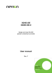
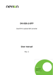
SYSTEM 7000
IRIS+
USER MANUAL
EMS 7000 IRIS +
Table of Contents
Section
Page No
1. INTRODUCTION ............................................................................................................. 3
2. THE DISPLAY................................................................................................................. 3
3. TRANSMITTERS ............................................................................................................. 6
4. MESSAGE PAGER SYSTEM ............................................................................................... 7
©2015 EMS Security Group Ltd. All rights reserved.
2
TSD251 Iss 3 25/06/15 AJM
EMS 7000 IRIS +
1. Introduction
1.1 The IRIS+ is a radio based personal attack system, that can be used as a stand
alone alarm system or integrated into other systems. Input to the system is via
transmitting devices. Output from the system is via 4 relays. The system is
configured by the installer during commissioning.
1.2 The system is operated by using the key switch, the 12 key membrane keypad and
by viewing the display which shows the status of the system at all times.
2. The Display
2.1 The IRIS+ has a 20 character by 4 line liquid crystal display LCD. The status of the
system is shown on the LCD.
2.2 Key In CLEAR: With the keyswitch in the ‘CLEAR’ position and under no alarm
condition, the display will be as shown in Figure 1 below: When the key is in this
position the system is ready to receive alarms. The actual text may show the name
of your premises or some other text as this is configurable during the
commissioning of the system.
System Clear
Date
Time
Figure 1
2.2 Key In RESET: With the key in the ‘RESET’ position, the display will be as shown
in Figure 2. When the key is in this position it will not receive ANY ALARMS. This
position is used to cancel an alarm using the key. Once the key has been turned to
the ‘RESET’ position it should be returned to the ‘CLEAR’ position. With the key in
the ‘RESET’ position authorised users can gain access to various functions within
the system. Access is via a 4 or 6 digit PIN.
***SYSTEM RESET***
Time
Figure 2
2.3 Key In Test: With the key in the ‘TEST’ position, the display is as shown in Figure
3. The ‘TEST’ position is used to test all of the transmitters. When testing
transmitters all levels of alarm for each transmitter on the system should be tested.
Operate
All
Transmitters
^ to END
TIME
Figure 3 Time
©2015 EMS Security Group Ltd. All rights reserved.
3
TSD251 Iss 3 25/06/15 AJM
EMS 7000 IRIS +
2.4 Full Alarm Received: When a full alarm is received with the key in the clear
position the display will be as shown in Figure 4. In the example shown transmitter
number 7 has generated the alarm. The text on your system may vary as
transmitters can be allocated names, in which case the transmitter name and not
its number will be displayed.
Item : 001 – At 11:25
Alarm : Handpush 007
^^^^^^^^^^^^^^^^^^^^
* HUA Alarm *
TIME
Figure 4
2.5
Local Alarm Received: When a local alarm is received with the key in the clear
position the display will be as shown in Figure 5. In the example shown
transmitter number 7 has generated the alarm. The text on your system may vary
as transmitters can be allocated names, in which case the transmitter name and
not its number will be displayed.
Item : 001 – At 11:25
Local : Handpush 007
^^^^^^^^^^^^^^^^^^^^
* HUA Local *
TIME
Figure 5
2.6 If more than one event has been logged by the receiver, the number next to ‘Item’
will be greater than ‘001’. Events in the ‘Item’ log can be viewed by using the ‘▲’
and ‘▼’ arrows. The ‘Item’ log is cleared when the key is turned to the reset
position.
2.7 Clearing an Alarm: When an alarm activation has occurred the display can be
cleared by inserting the key, turning it to the ‘RESET’ position and back to the
‘CLEAR’ position.
2.8 Internal Sounders: The IRIS+ receiver makes 3 distinctive types of sound, a high
pitched sound which we will call sounder 1 a slightly lower pitch sound which will be
known as sounder 2 and both sounder 1 and 2 alternating at approximately half
second intervals which will be known as sounder 3. These sounders are
programmable and will be set up when the system is installed. If the sounders on
your system do not function in the way described below then your system has been
configured with one or more of the sounder functions disabled. To change the
sounder configuration contact your installer who will be able to carry out the reconfiguration.
©2015 EMS Security Group Ltd. All rights reserved.
4
TSD251 Iss 3 25/06/15 AJM
EMS 7000 IRIS +
2.9 Tamper: The IRIS+ receiver is protected by anti tamper devices. If the antenna is
removed from the receiver or the receiver case is opened the tamper alarm will
activate and sounder 3 will come on. In addition the display will show that a tamper
event has occurred. Figure 6 below shows an aerial tamper. If an aerial tamper has
occurred, restore the aerial to the receiver and reset the system as described in
para 2.7.
Item : 001 – At 11:25
Main Receiver
Aerial Tampered
* Tamper*
TIME
Figure 6
2.10 Interference: The receiver is designed to recognise if there is another radio
transmitter working on the same frequency, and is likely to interfere with the
system. In the instance of any such interference, it will be indicated by the
presence of an asterisk ' * ' displayed between the time and date on the bottom
line of the display window, as shown in Figure 7. Should the interference persist,
the panels internal buzzer will sound, and a persistant RFI fault will appear, as
shown in Figure 8. Once the interference stops, the buzzer will silence and the fault
screen will change, (the asterix disappears), as shown in Figure 9. It should be
noted that the presence of another signal will not prevent the alarm system from
operating normally.
System Clear
Date
*
Time
Figure 7
Item: 001
At 11:25
Persistent RFI
^^^^^^^^^^^^^^^^^^^
Date
* Time
Figure 8
Item: 001
At 11:25
Persistent RFI
^^^^^^^^^^^^^^^^^^^
Date
Time
Figure 9
2.11 Whenever a key is pressed the IRIS+ receiver will emit a short bleep. If the key
pressed is valid then a short bleep will occur, if an invalid key is pressed a longer
bleep occurs.
2.12 The configuration of your system will determine how your sounders work. As a
general rule the internal sounders operate as follows. If the key is moved from the
‘CLEAR’ position to the ‘RESET’ or ‘TEST’ position sounder 2 will come on.
©2015 EMS Security Group Ltd. All rights reserved.
5
TSD251 Iss 3 25/06/15 AJM
EMS 7000 IRIS +
3. Transmitters
3.1 Handpush Transmitters: The handpush transmitter is shown in Figure 10. Its
operation when configured as an opposed action device is shown below:
Green Push-button pressed
Local Alarm Initiated.
Red Push-button pressed
No effect.
Both Red Push-buttons pressed together
Full Alarm Initiated.
7500 Handpush Transmitter
Green Button
Red Button
Red Button
Figure 10
3.2 Alarm Latch: If on the pressing of a single Red button the internal red LED lights,
this indicates a Full Alarm has been initiated from the hand push within the last 24
hours.
3.3 Battery Low Indication: Battery conditions can be viewed on a Local or Full Alarm
activation. If the yellow battery LED is present, the battery voltage in the handpush
is low and therefore require replacement.
After replacing the batteries, it is recommended that the device is tested to ensure
the batteries have been inserted correctly and the device has been returned to a
fully operational condition.
©2015 EMS Security Group Ltd. All rights reserved.
6
TSD251 Iss 3 25/06/15 AJM
EMS 7000 IRIS +
4. Message Pager System
4.1
Pager Receiver: The full operation of the pager receiver, shown in Figure 11, is
given in booklet that accompanies the device. A brief summary of the main
features and their operation is included as a quick reference. To turn the unit on,
press and hold key ‘A’ for approximately two seconds. The pager will go through
its start up sequence. The pager has two storage areas, a Read Area which stores
messages as they are received and an Archive Area which is used for the longer
term storage of messages. When the Read message area is full messages will
require deleting. It therefore follows that if a message is likely to be needed for a
long period of time it should be moved to the Archive message area.
Pager Receiver
UP
DOWN
B
A
Figure 11
4.2
To clear a message from the Read message store press the ‘A’ key to view the list
of messages currently present.
4.3
Press the ‘UP’ and ‘DOWN’ keys to highlight the desired message. Once
highlighted, press the ‘A’ key. The display will change to show the message.
4.4
By pressing the ‘B’ key the following icons wil be displayed: -
Archive
4.5
Delete Single
Delete All
Press the ‘UP’ and ‘DOWN’ keys to highlight the desired Icon. Once highlighted,
press the ‘A’ key, to confirm the action.
©2015 EMS Security Group Ltd. All rights reserved.
7
TSD251 Iss 3 25/06/15 AJM
EMS 7000 IRIS +
©2015 EMS Security Group Ltd. All rights reserved.
8
TSD251 Iss 3 25/06/15 AJM