1
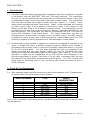
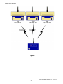
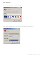
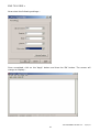
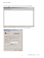
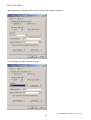
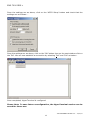
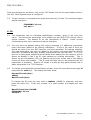
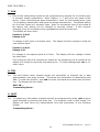
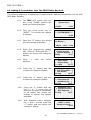
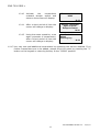
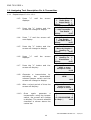
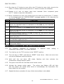
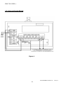
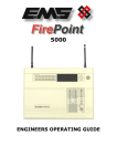
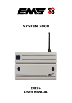
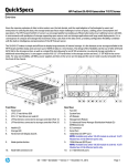
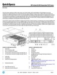
SYSTEM 7000
7940
HIGH POWERED UHF
CONTACT OPERATED TRANSMITTER
INSTALLATION AND PROGRAMMING
INSTRUCTIONS
EMS 7000 IRIS +
Table of Contents
Section
Page No
1. INTRODUCTION............................................................................................................. 3
2. TOOLS & TEST EQUIPMENT............................................................................................. 3
3. EQUIPMENT REQUIRED: ................................................................................................. 4
4. PROGRAMMING CONNECTION DETAILS ............................................................................ 6
5. TRANSMITTER PROGRAMMING ........................................................................................ 7
6. ID.............................................................................................................................. 14
7. CON ........................................................................................................................... 15
8. TXD ........................................................................................................................... 15
9. QUIT .......................................................................................................................... 15
10. ADDING A TRANSMITTER INTO THE IRIS RADIO RECEIVER ............................................ 16
11. ASSIGNING TEXT DESCRIPTION FOR A TRANSMITTER ................................................... 18
12. ADDING A TRANSMITTER INTO THE 7703 RADIO RECEIVER............................................ 19
13. INTERNAL INPUT WIRING ........................................................................................... 20
7940 ENGINEERS GUIDE v2.2 – 13/04/10
2
EMS 7000 IRIS +
1. Introduction
1.1 The high powered contact operated UHF transmitter has been designed to operate
in conjunction with the EMS IRIS 7256 and 7703 radio receivers. The transmitter
unit is a 12 volt operated device and comprises of a 500mW transmitter, fitted with
an additional printed circuit board with eight opto isolated inputs. The transmitter
only uses four of these opto isolated inputs; these are inputs 1, 2, 7 and 8. These
inputs when activated transmit fixed events. Input 1 when activated will transmit
an alarm event, input 2 will transmit a local event, input 7 will transmit a low
battery event and input 8 will transmit a tamper event. The transmitter can be
programmed into the IRIS receiver therefore allowing individual identification via
text descriptions. The transmitter can also be programmed into the 7703 receiver
giving LED indication of an alarm event. The inputs themselves can also be
programmed to operate either normally open or normally closed. The IRIS receiver
is capable of having a maximum of 256 transmitters in total added, whist the 7703
receiver is capable of having a maximum of 48 transmitters in total added.
1.2 As each input is opto isolated, a negative is required to be applied to one side of the
input. To trigger the input, a positive voltage should be applied if the contact is
programmed as normally open or removed if normally closed (see Figure 4, on page
20, for full wiring details). The unit when supplied will have the negatives of the
inputs pre-wired and the units tamper switch will also be pre-wired with both
positive and negative connections taken to the tamper input (input 8). On an input
activation a signal will be transmitted to an IRIS receiver and displayed in the
format programmed i.e Alarm: Zone Area 1 for an input 1 activation with the text
description of the transmitter programmed as Zone Area 1. If a 7703 receiver was
being used on activating input 1, the red Alarm LED would illuminate to give a
visual indication.
2. Tools & Test Equipment
2.1 Only standard hand tools are required to install the transmitter unit. The transmitter
is supplied with the inputs factory set as follows:-
INPUT NUMBER
TYPE
INPUT
ORIENTATION
1
2
3
4
5
6
7
8
Alarm
Local
Not Used
Not Used
Not Used
Not Used
Low Battery
Tamper
Normally Open
Normally Open
N/A
N/A
N/A
N/A
Normally Open
Normally Closed
If an inputs orientation requires alteration, Windows HyperTerminal with a serial a lead
will be required.
7940 ENGINEERS GUIDE v2.2 – 13/04/10
3
EMS 7000 IRIS +
3. Equipment Required:
7940 Contact Operated Transmitter
7256 IRIS Receiver with standard 7200 software or 7703 Receiver
Power Supply Units
Windows HyperTerminal with serial lead if programming changes
are required.
3.1
Remote devices and high gain aerials may also be required for range extension,
depending upon the customer’s specification and requirements. Please note both
the contact operated transmitter and the IRIS receiver will require an external
power supply, whilst the 7703 receiver is available with a built in power supply
part number 7703/P. Figure 1 shows a typical IRIS radio system, whilst Figure 2
shows an alternative system using a Single Channel 7703 Receiver:-
7940
Half Watt Txer
Four Input Data
Transmissions
7940
Half Watt Txer
7940
Half Watt Txer
Four Input Data
Transmissions
7256 IRIS+ Rxer
Figure 1
7940 ENGINEERS GUIDE v2.2 – 13/04/10
4
EMS 7000 IRIS +
7940
Half Watt Txer
Four Input Data
Transmissions
7940
Half Watt Txer
7940
Half Watt Txer
Four Input Data
Transmissions
7703 Rxer
Figure 2
7940 ENGINEERS GUIDE v2.2 – 13/04/10
5
EMS 7000 IRIS +
4. Programming Connection Details
4.1 The computer to transmitter physical connection details are as follows:COMPUTER
ISOLATED RS 232 PORT
PIN 2 ---------------------------------- TX OUT
PIN 3 ---------------------------------- RX IN
PIN 5 ---------------------------------- COMMON CONNECT
4.2 All Computer to HyperTerminal connections are shown below in Figure 3.
TO
POWER
SUPPLY
9 PIN
SERIAL
CONNECTOR
+
-
2
3
5
TAMPER
LOOP
0V 12V
DC
SUPPLY
COMMON
RX-
RX+
CONNECT
ISOLATED RS485
RX
IN
TX COMMON
OUT CONNECT
ISOLATED RS232
Figure 3
7940 ENGINEERS GUIDE v2.2 – 13/04/10
6
EMS 7000 IRIS +
5. Transmitter Programming
5.1
The transmitter unit has the facility of changing it’s inputs orientation and also the
unique identity code for the transmitter can be programmed. The settings for the
transmitter are as follows with the menu commands required shown in brackets:Inputs unique identification code (ID). Orientation of the input to normally open
or normally closed (CON). A full explanation of the input settings and the
operation of the inputs is described in more detail in the following paragraphs
under their menu commands headings.
5.2
To allow access into the programming menu the computer should be set up with
Windows HyperTerminal as follows:PLEASE NOTE: Examples shown below are from Windows XP. Other
versions of Windows may vary.
To start a new HyperTerminal session, click on the ‘Start’ button.
Then select ‘Programs’ and then ‘Accessories’.
Now select ‘Communications’, then ‘HyperTerminal’.
You will then be presented with the following screen: -
7940 ENGINEERS GUIDE v2.2 – 13/04/10
7
EMS 7000 IRIS +
Now enter your desired connection description: -
Then click on the ‘OK’ button, and the screen will change to the following: -
7940 ENGINEERS GUIDE v2.2 – 13/04/10
8
EMS 7000 IRIS +
Now select the Comm Port required as below: -
7940 ENGINEERS GUIDE v2.2 – 13/04/10
9
EMS 7000 IRIS +
Now select the following settings: -
Once completed, click on the ‘Apply’ button and then the ‘OK’ button. The screen will
change to display: -
7940 ENGINEERS GUIDE v2.2 – 13/04/10
10
EMS 7000 IRIS +
Now select ‘Call’ and ‘Disconnect and the screen will change to display: -
Now select ‘File’ and ‘Properties’. The screen will change to display:-
7940 ENGINEERS GUIDE v2.2 – 13/04/10
11
EMS 7000 IRIS +
Now select the ‘Settings’ tab and the screen will change as below: -
The Settings should be set as follows: -
7940 ENGINEERS GUIDE v2.2 – 13/04/10
12
EMS 7000 IRIS +
Once the settings are as above, click on the ‘ASCII Setup‘ button and check that the
settings are as follows: -
Once the settings are as above, click on the ‘OK’ button then on the next window click on
the ‘OK’. We can now establish a connection by selecting ‘Call’ and ‘Call’ as below:-
Once completed, HyperTerminal is configured.
Please Note: To save future reconfiguration, the HyperTerminal session can be
saved for future use.
7940 ENGINEERS GUIDE v2.2 – 13/04/10
13
EMS 7000 IRIS +
Once the settings are as above, click on the ‘OK’ button then on the next window click on
the ‘OK’. Now Hyperterminal is configured.
5.3 To gain access to command menu press the enter key 3 times. The terminal display
should change to:COMMAND id, con,
txd, quit >
6. ID
6.1 The transmitter has an individual identification number, which is set from this
menu. This allows the transmitter to be added into the IRIS/7703 receiver with a
unique number. The default ID for the transmitter is 1846A. Under normal
circumstances this menu should not require changing.
6.2 The only time the default setting will require changing is if additional transmitter
units have been added to an existing installation. If this is the case a print out
should be taken from the IRIS Receiver and the transmitter ID settings checked.
The new transmitter can then be added to the system ensuring that the new ID
does NOT correspond with any already programmed into the IRIS unit. If a 7703
receiver is being used, additional transmitters when adding into the receiver, will be
shown as already in use if an ID code matches an existing transmitter. This is
shown by the Low Battery LED not flashing three times at the end of the adding
routine to show confirmation. The ID code will then have to be changed until the
transmitter is accepted. Section 12 shows in a step by step guide format how to
add a transmitter to a 7703 Receiver.
6.3 To change the transmitters identification number, from the command menu type id
and press the enter key. The display will then show:
Current ID code (hex)
1846A
New ID code (hex)
To change the ID enter the new code in capitals (1846B for example) and then
press the enter key. If the hex number is a valid number the display will now
show:
New ID Code (hex) 1846B
COMMAND id, con
txd,quit >
7940 ENGINEERS GUIDE v2.2 – 13/04/10
14
EMS 7000 IRIS +
7. CON
7.1 Each of the transmitters inputs can be programmed to operate via a normally open
or normally closed configuration. Note: Inputs 1, 2, 7 and 8 are only used on this
device. Input 1 activating an alarm transmission, input 2 a local transmission, input
7 a low battery transmission and input 8 a tamper transmission. The default setting
for all of the inputs is to normally open. Note: As the tamper input is pre-wired at
the factory this setting will be changed to normally closed. If this requires
changing, from the command menu type con and press the enter key.
The display will then show:
Contact 1 is N/O
Change Y/N
To change to N/C press Y and then enter. The display will then change to show the
next contact input:
Contact 2 is N/O
Change Y/N
If a change is not required press N or Enter. The display will then change to show
the next input.
This continues until all 8 contacts are looked at. On answering Y/N to contact 8 the
display will change to show the command menu. To check settings type con to reenter menu.
8. TXD
8.1 The txd function when entered causes the transmitter to transmit call in data
approximately once every second. This shows the transmitter is transmitting valid
data. To enter this function, type txd from the command menu and press the enter
key. The display will then show,
CALL IN....
Transmitting Burst...
9. QUIT
9.1 To update any information changed and exit the programming mode, quit must be
typed followed by pressing the enter key. The program mode is then exited. The
display will then show any transmissions from the transmitter in the following
format:
Transmitting Burst...
7940 ENGINEERS GUIDE v2.2 – 13/04/10
15
EMS 7000 IRIS +
10. Adding A Transmitter Into The IRIS Radio Receiver
The following sequence of operations is required when adding a transmitter into the UHF
IRIS Radio Receiver.
10.1
The IRIS LCD screen with the
key in the “CLEAR” position will
show the following display:
System Clear
01/10/93
10.2
Turn the front panel key to
“RESET”. The screen will change
to display:
13:26
*** SYSTEM RESET ***
13:26
10.3
Press the “0” button, the screen
will now change to display:
Enter Your PIN
For Menus > _
=Done =Del 13:26
10.4
Enter the engineering default
PIN: “221100” and press the “”
button, the screen will change to
display:
| ** Main Menu **
|
> Pins & Access
<
| System Support |
2=Help
13:27
10.5
Press “”
displays:
screen
| Time and Date |
> Radio Setup
<
| Output Setup
|
2 = Help
16: 37
10.6
Press the “1” button and the
screen will change to display:
| ** Radio Setup ** |
> Add Transmitter <
| Txer Details
|
2 = Help
16:37
10.7
Press the “1” button and the
screen will change to display:
| Add Transmitter |
> Add Handpush <
| Add Moneyclip |
2 = Help
16:37
10.8
Press the “1” button and use
the “” or “” arrow keys to
highlight the type of transmitter
to be added, the screen will
change to display the options
available:
| Handpush Type |
> Opposed Action <
| Non-Opposed |
2 = Help
16:37
10.9
With Opposed Action between
the > and < arrows press the
“1” button and the screen will
change to display:
Operate Transmitter
NOW or press
Escape to cancel
16:38
until
the
7940 ENGINEERS GUIDE v2.2 – 13/04/10
16
EMS 7000 IRIS +
10.10
Activate
the
transmitters
onboard tamper switch and
observe the screen will display:
Release all buttons
NOW
16:38
10.11
After a short period of time the
screen will change to display:
10.12
Using the same operation, once
again generate a transmission,
after a short period of time the
screen will change to display:
Operate Transmitter
Again or press
Escape to cancel
16:38
Hand Push 001
Added
Push any key
16:38
10.13 You may now add additional transmitters by repeating the actions detailed. If no
further transmitters are to be added, escape from this menu by pressing the “3”
button on the keypad or returning the key to the “CLEAR” position.
7940 ENGINEERS GUIDE v2.2 – 13/04/10
17
EMS 7000 IRIS +
11. Assigning Text Description For A Transmitter
11.1
Repeat steps 10.1 to 10.4.
11.2
Press “”
displays:
screen
| Time and Date |
> Radio Setup <
| Output Setup |
2=Help
16: 37
11.3
Press the “1” button and the
screen will change to display:
| ** Radio Setup ** |
> Add Transmitter <
|
Txer Details
|
2=Help
16:37
11.4
Press “” and the screen will
now display:
| Add Transmitter |
> Txer Details <
| Set Radio Rules |
2=Help
16:37
11.5
Press the “1” button and the
screen will change to display:
| - Txer Details - |
> Name by Number <
|
Name by Tx
|
2=Help
16:37
11.6
Press “”
displays:
screen
| Name by Number |
>
Name by Tx <
|
View Names
|
2=Help
16:37
11.7
Press the “1” button and the
screen will display:
Operate Transmitter
NOW or press
Escape to cancel
16:38
11.8
Generate a transmission by
activating
the
transmitters
onboard tamper switch and the
screen will change to display:
Release all buttons
NOW
After a short period of time the
screen will display:
Operate Transmitter
Again or press
Escape to cancel
16:38
Once
again
generate
a
transmission using the tamper
switch, the screen will change
to display: The current selected
character is shown above the
centre bar.
|
|
|
|
4< IJKL M NOPQR >6
2 = Help |
16:38
11.9
11.10
until
until
the
the
16:38
7940 ENGINEERS GUIDE v2.2 – 13/04/10
18
EMS 7000 IRIS +
11.11 By using the “4” button to move left or the “6” button to move right, move to the
letter or number required and press the “5” button to select the character.
11.12 Repeat 11.11 until all letters have been selected. Once completed press
the “” button to save the information.
11.13 Once completed you may now escape from this menu by pressing the “3” button
on the keypad until the “SYSTEM RESET” message appears, or by returning the
key to the “CLEAR” position.
KEY
FUNCTION
0
Enters a blank space into the new device name being entered.
3
Exits to the previous menu
4
Moves the alphabet wheel of characters to the Left, by one character
space at a time.
5
Enters the character in the centre directly above the character selector
|.
6
Moves the alphabet wheel of characters to the Right, by one character
space at a time.
7
Moves the flashing cursor to the left, through the new device name by
one character space at a time.
8
Moves the alphabet wheel of characters to the Right, by 12 character
Spaces at a time.
9
Moves the flashing cursor to the Right, through the new device name by
one character space at a time.
Backspace Key, Deletes by one character. (Deletes to the left only)
Saves and completes the current activity and returns the program to the
appropriate display.
12. Adding A Transmitter Into The 7703 Radio Receiver
12.1
The following sequence of operations
transmitter into the UHF 7703 Radio Receiver.
12.2
Turn the key on the 7703 receiver to the “RESET” position.
12.3
Turn the key to “TEST” and back to “RESET” three times. Allow not more than
one second between switching actions.
12.4
Wait until the red alarm LED
transmitters onboard tamper switch.
12.5
The green Local LED will now flash and a buzzer sound.
12.6
Activate the tamper switch again.
The yellow Low Battery LED will light
and the buzzer will sound three times to acknowledge the transmitter has
been added into the system.
12.7
Repeat the above procedure for any further transmitters to be added.
starts
is
required
flashing
and
when
then
adding
activate
a
the
7940 ENGINEERS GUIDE v2.2 – 13/04/10
19
EMS 7000 IRIS +
13. Internal Input Wiring
Figure 4
7940 ENGINEERS GUIDE v2.2 – 13/04/10
20
EMS 7000 IRIS +
7940 ENGINEERS GUIDE v2.2 – 13/04/10
21
EMS 7000 IRIS +
Dealer Information:
EMS Group Head Office
Technology House,
Sea Street
Herne Bay,
Kent CT6 8JZ
England
Tel: +44 (0) 8712 710804
Fax: +44 (0) 1227 369679
Email: [email protected]
The information contained within this literature is
correct at time of publishing. The EMS Group reserves
the right to change any information regarding
products as part of its continual development
enhancing new technology and reliability. The EMS
Group advises that any product literature issue
numbers are checked with its head office prior to any
formal specifications being written.
www.emsgroup.co.uk
7940 ENGINEERS GUIDE v2.2 – 13/04/10
22