1
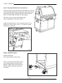
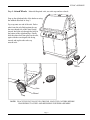
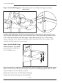
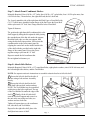
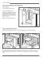
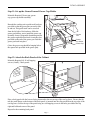
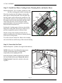
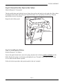
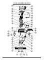
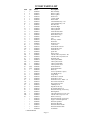
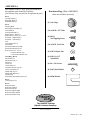
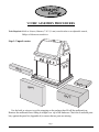
VC200C ASSEMBLY PROCEDURES
Tools Required: Knife or Scissors, Hammer, 7/16” (11 mm) wrench/ratchet or an adjustable wrench,
Philips or Robertson screwdriver.
Step 1: Unpack carton
VERMONT
astin
C
gs
GS
ASTIN
ONT C
VERM
Box #
4
Box #
Box #
1
3
Box #
2
Use the knife or scissors to cut the strapping on the package then lift off the cardboard cap.
Remove the cardboard sleeve lifting it straight over top of the barbecue. Check the 4 enclosed parts
kits, against the parts list (Appendix A) to ensure that no parts are missing.
Page 1
VC200C ASSEMBLY
VERMONT
Castings
Step 2: Prop up left hand side of the barbecue
In order to attach casters and wheels to the barbecue, each side
of the unit must alternately be propped up to provide access to
the bottom of the legs. A block of wood or other solid item
about 4-6 inches high will suffice for this purpose.
The same process can be used with the right
legs for attachment of the unit’s wheels.
NOTE: BEFORE BEGINNING ANY ASSEMBLY, REMOVE THE
BARBECUE’S BASE PANELS (See Fig. 1) TO PERVENT THEM
FROM BEING DAMAGED.
2
Hand Hold
(Lift Up and Pull Out)
1
Shoulder
Screws
Fig. 1
Step 3: Install Casters
Materials Required:
Two casters and two caster inserts.
Place a caster insert in the bottom of the
rear left leg and tap it into place with a
hammer. Tap the other caster insert into
the front left leg. Snap the casters into
the inserts.
Caster
Page 2
Insert
VC200C ASSEMBLY
Step 4: Attach Wheels Materials Required: axle; two axle caps and two wheels.
VERMONT
Castings
Prop up the right hand side of the barbecue using
the method described in Step 2.
Tap a cap onto one end of the axle. Push a
wheel onto the axle flush against the cap,
the cone shaped side of the wheel facing
inward. Insert the axle through the holes at
the bottom of the right hand legs. Finally
slide the other wheel into place on the axle,
again with the cone shaped side facing
inward, and tap the other axle cap
onto the axle.
Caps
Axle
Wheels
Axle
Wheel
Cap
NOTE: PLACE THE UNIT ON LEVEL GROUND. LOCK THE CASTERS BEFORE
PROCEEDING TO STEP 5 AND BEGINNING FURTHER ASSEMBLY.
Page 3
VC200C ASSEMBLY
Step 5: Attach Shelf Supports Materials Required: Left and Right shelf supports and eight
shim washers.
Shim
Attach the right shelf support to the barbecue by loosening the 4 existing leg bolts, approximately 3 turns
only, so that the shelf support can slide over the bolt heads. Insert a shim washer sideways behind the head
of one of the bolts and in front of the shelf support. Tighten the bolt using the 7/16” (11 mm) wrench/
ratchet or adjustable wrench. Repeat inserting shim washers behind the heads of the remaining 3 bolts.
Attach the left shelf support in the same manner.
Step 6: Install Handle Grips
Materials Required: Three handle
grip sets (six pieces total) and six
#4 x 3/4” Philips screws.
S
STING
NT CA
O
M
VER
V
ER
M
O
N
T
s
ng
sti
Ca
Place the top half of one handle grip, the half bearing the Vermont Castings logo, onto the right shelf support
handle. Use the holes provided as a guide. Snap the two halves of the handle grip together and secure them
using two Philips screws and a Philips screwdriver.
Repeat this procedure for the left shelf support handle grip.
Finally, attach the last handle grip to the front lid handle.
Page 4
VC200C ASSEMBLY
Step 7: Attach Front Condiment Shelves
Materials Required: Four #10-24 x 1/2” bolts; four #10-24 x 1/4” nylon bolts; four # 10-24 nylon nuts; four
#10-24 lock nuts; 2 front shelves; the right shelf end; the left shelf end.
7a - Loosely attach the side of the right front shelf End Cap to a Front Shelf with
(2) 1/2” bolts & nuts. Attach the bottom flange of the End Cap to the Front Shelf
with a nylon nut & 1/4” bolt. Note: Flange should be below Front Shelf.
Tigten all fasteners.
Lock
Nuts
1/4" Bolts
7b - position the right front shelf (condiment bin) to the
shelf support by tilting the bin upwards while passing
the extended arm of the bin side under the support.
Hook the back edge over the arm support, then
swing the bin down into position. Next secure the
comdiment bin to the front control panel by
aligning the center hole on the inside bottom side
of the shelf with the provided on the right side
flange of the control panel. Screw the pieces
together using a nylon nut & 1/4” bolt.
S
STING
NT CA
O
M
VER
1/2"
Bolts
Nylon
Nut
VE
RM
ON
T
s
ng
sti
Ca
Repeat to attach the left condiment bin.
1/4" Bolt
Do not tighten he fasteners yet.
Nylon
Nut
Step 8: Attach Side Shelves
Materials Required: Nine #10-24 x 1/2” round head bolts; eight plastic washers, nine #10-24 lock nuts; and
the left and right side shelves, and the Tool Holder.
NOTE: See separate rotisserie instructions to assemble rotisserie bracket to left side shelf.
1 Secure the left side shelf to the side of
the base using a bolt and nut. Assembly
loosely.
2 Secure the left side shelf to the left
front shelf with one bolt, washer and nut.
NOTE: The Tool Holder may be assembled
at this time to the left or right end. The top
of the Tool Holder fits under the edge of the
shelf. 3 Finally, fit the left side shelf
onto the left shelf support and secure it to
the unit at the rear using two bolts, two
washers and two lock nuts.
3
Bolt
Washer
(4)
1
ing
s
2
Bolt
Tighten all connections on the condiment
bin, side shelf, and Tool Holder.
Nut
Nut
VE
RM
CaON
st T
Tool Holder
Repeat for the right side shelf, place side
shelf plate into center of shelf.
Page 5
Bolt
VC200C ASSEMBLY
Step 9: Attach the Handles to the Cabinet Doors
Materials Required:
Two door handles with four screws.
Attach a door handle to the left
cabinet door by aligning the ends of the
handle with the two holes provided on
the top right side of the door. Secure the
handle using the screws provided and a
Philips screwdriver.
Repeat for the right hand door handle.
Step 10: Insert the Bottom Panels
Materials Required: Two bottom panels. Four #8-18 self-tapping screws for Propane Model Only.
Bottom
Panel
Bottom
Panel
Screws
Bottom Panel
For Propane
Models
Bottom
Panel
Natural Gas Model
Propane Model
Insert the bottom panels of the cabinet by placing the lips of the panels on the front and rear leg brace. For
Propane Models, the panel with the holes is to be placed on the right and secured with four self-tapping
screws.
Page 6
VC200C ASSEMBLY
Step 11: Set up the Grease Pan and Grease Cup Holder
Materials Required: Grease pan; grease
cup, grease cup holder assembly.
Beneath the cooking unit a guide track has been
provided so that the grease pan can easily slide
in and out. This guide track can be accessed
from the left side of the barbecue. Slide the
grease pan halfway out to install the grease cup
assembly. Insert a disposable aluminum pan into
the grease cup holder then hook it onto the slots
provided on the end of the grease pan. Push the
grease pan back into place.
Grease
Pan
Grease
Cup Holder
Grease Cup
(Note: the grease cup should be hanging below
the square hole provided in the grease pan).
Step 12: Attach the Back Panels of the Cabinet
Materials Required: #8-18 self-tapping
screws (4 total); 2 back panels.
Tab
Place a back panel with the louvers facing down and to the rear on top of the rear leg brace. Ensure that the
tab, the small flange on the bottom of the back panel, is inserted into the slits provided on the top edge of the
rear leg brace. Secure the top of the panel using two self-tapping screws in the holes provided at the top
right and left hand corner of the panel.
Repeat for the remaining back panel.
Page 7
VC200C ASSEMBLY
Step 13: Install Sear Plates, Cooking Grates, Warming Rack, and Smoker Boxes
Materials Required: Two sear plates; smoker box with
lid; three cooking grates, and the warming rack.
Position the 3 cooking grates in the base unit with the
finger holes to the front. These may be turned over to
provide an angled flat surface for delicate foods.
Slip the rear lip of the warming rack into the two
supports extruding above the rotisserie burning housing.
Let it rest in a level position.
To use the rotisserie smoker box. Remove the warming
rack, and sit the box and lid on top of the rotisserie housing.
Step 14: Insert the Gas Tank
Materials Required: Cylinder. (Not supplied with barbecue)
NOTE: Refer to the Users Manual for the propane
cylinder specifications and for cylinderfilling
requirements, before lighting the Grill.
Insert the propane cylinder into the hole provided in
the bottom right bottom panel. Ensure the valve is
facing foreward. Connect the cylinder to the main
regulator.
Page 8
Sear
Plates (2)
Cooking
Grates (3)
Warming
Rack (1)
Ca
s
ng
sti
VE
RM
ON
T
Place the sear plates into the barbecue ensuring that
their edges are facing downward. The sear plate with
the large square cutout will house the smoker box. The
plate with the smoker box hole should be placed so that
it is closer to the rear of the unit on the left side of the
Grill. If the plates have arrows stamped on them,
position the plates so the arrows point to each other.
Place the lid on the smoker box.
Smoker
Box
Finger
Hole
VC200C ASSEMBLY
Step 15: Reinstall the Base Panels of the Cabinet
Materials Required: 2 base panels
Take the smaller base panel with the louvers facing down and out and attach it to the right side of the cabinet
by sliding the holes on the side of the panel onto the shoulder screws protruding from the legs. Push the
panel down to secure it in position.
Repeat for the left base panel.
1
2
Hand Hold
(Lift Up and Pull Out)
Shoulder
Screws
Step 16: Install Ignitor Battery
Materials Required: ‘AA’ Battery
Unscew the ignitor button knob, remove the spring, and place the AA battery positive end down into the
holder. Replace the spring over the battery and tighten the cap. The ignitor should make an audible snap
every second when the button is pushed.
Follow the leak test procedure and operation guide in the user’s manual.
Page 9
VC200C ASSEMBLY DRAWING
Page 10
VC200C PARTS LIST
Item
Qty
Part #
Description
1
2
3
4
5
6
7a
7b
8
9
10
11
12
13
14
15
16
17
18
19
20
21a
21b
22
23
24
25a
25b
26
27a
27b
28a
28b
29
30
31
32
33
34
35a
35b
36
37a
37b
38
39
40
41
43
44a
44b
45
-
1
2
1
2
1
2
1
1
1
1
1
1
1
1
1
1
1
1
1
1
1
1
1
1
1
4
1
1
1
1
1
1
1
1(0)*
1(2)*
1
1
1
1
1
1
2
1
1
6
1
1
1
1
1
1
1
1
1
1
1
1
1
1
50000899
50000236
50000237
50000738
50000429
50000038
50000919
50000470
50000356
50000099
50000441
50000442
50000431
50000523
50000047
50000466
50000093
50000357
50000043
50000430
VCCG1A
50000130
50000283
50000439
50000438
50000076
50000456
50000455
50000097
50000414
50000446
50000419
50000449
50000096
50000095
50000360
50000361
50000642
50000967
50000129
50000282
50000369
50000363
50000366
50000365
50000248
50000355
50000746
50000261
50000454
50000453
50000433
50000747
50000399
50000286
50000287
50000541
50000151
50000504
Base Assembly
Brace Leg End
Brace Leg Rear
Shelf Front
Console 200 B
Burner Main
Valve/Manifold Assy - NG
Valve Manifold Assy - LP
Plate Heat Set
Shelf Side Right
End Cap Shelf R
End Cap Shelf L
Electrode Main Short
Electrode Main Long
Burner Rotiss Assy
Electrode Rotiss
Axle
Box Assy - Smoke
Flash Tube
Deflector Oven
Cook Grates
Panel Base R Charcoal
Panel Base R Green
Electrode Oven
Igniter Kit
Knob Control
Tube & Orifice Assy Rotiss - NG
Tube & Orifice Assy Rotiss LP
Shelf Side Left
Lid Assy Rear Black
Lid Assy Rear Green
Lid Assy Front Black
Lid Assy Front Green
Panel Bottom LP
Panel Bottom Plain
Wheel (2)
Grease Cup Holder / cups(2)
Grip Handle Set (3)
Gauge Temp
Panel Base L Charcoal
Panel Base L Green
Panel Rear Lower – Black – set
Door Front Charcoal Set
Door Front Green Set
Lid Bumpers Set
Regulator/O.D. Assy
Pivot Pin & Bolt Set (2)
Rotisserie Housing / Screen Assy
Warming Rack
Tube and Orifice Assy Oven - NG
Tube & Orifice Assy Oven - LP
Burner Oven Assy
Rotisserie Housing / Screen Assy
Support - Rotisserie Spit Rod
Rotisserie Spit Rod
Rotisserie Work Kit
Rotisserie Motor Bracket
Rotisserie Bracket Guide
Tool Holder
* Natural Models
Page 11
APPENDIX A
The contents of the VC200C parts kits included in
the appliance pack should be as follows:
(For reference only, see parts list for replacement parts)
Box 1:
Left Side Shelf (1)
Right Side Shelf (1)
Side Shelf Plate (1)
Box 2:
Warming Rack
Shelf Support Assembly (2)
Front Shelf (2)
Front Shelf End-R (1)
Bottom Panel – Tank (1) *
Bottom Panel – Plain (1) * or (2)**
Sear Plate – Right Hand (1)
Sear Plate – Left Hand (1)
Axle
Front Shelf End-L (1)
Tool Holder
Smoker Box-Rotisserie Body
Smoker Box-Rotisserie Lid
Rear Panel Lower - Set (2)
* Propane Models Only
** Natural Gas Models Only
Parts Bag: (Box 2)
Smoker Box (1)
Smoker Box Lid (1)
Wheels (2)
Casters (2)
Caster Inserts (2)
Aluminum Grease Cups (2)
Grease Cup Holder (1)
Handle Grip Top (3)
Handle Grip Bottom (3)
Hardware kit
Door Handle and mounting screws (2)
Hardware Bag: (Part # 50000452)
(Parts not available separately)
(2) Axle Caps
(14) #10-24 x 1/2” Bolt
(8) #8-18
Self Tapping Screw
(14) #10-24 Lock Nut
(4) #10-24 Nylon Nut
(4) #10-24 x 1/4”
Nylon Bolt
(6) #4 x 3/4 Screws
(8) #10 Nylon Washer
(8) Shim Washer
Box 3:
Cooking Grates (3)
Box 4:
Rotisserie Motor
Rotisserie Spit Rod
Rotisserie Fork Kit
Rotisserie Support-Right
Rotisserie Motor Bracket
Rotisserie Bracket Guide
The Vermont Castings
Majestic Products Company
410 Admiral Blvd. • Mississauga, Ontario, Canada L5T 2N6 • 905-670-7777
www.vermontcastings.com
50000954 Rev. 0 0801