1
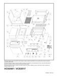
VCS3507 / VCS3517 ASSEMBLY PROCEDURES
Tools Required: knife or scissors, #2 and #3 Phillips or Robertson (square head) screwdriver,
7/16” and 3/8” wrench or ratchet, hammer, flat head screwdriver.
Step 1: Unpack Carton and Verify Contents
Use a sharp cutting tool to cut the straps on the packaging and then open the carton top. The sleeve
surrounding the barbecue can be removed by lifting it straight up and over the top of the unit. Unpack all
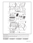
parts and compare all contents to the parts list that accompanies this assembly manual. Next, remove the
protective plastic coverings from the metal parts. Be careful not to scratch or damage the finish of the metal
parts when removing the protective plastic. Refer to the parts list for fastener detail.
CAUTION: Some parts may have sharp edges; to avoid injury, wearing gloves during assembly is strongly
recommended
Page 1
50004061 11/06 Rev.0 En
VCS3507 / VCS3517 Assembly
Step 2:Attach the Caster Inserts to the Cabinet sides
Parts Required:
(2) Cabinet Sides
(4) Caster Inserts
Insert one (1) Caster Insert into both bottom corners of the
cabinet end and ensure they are fully pushed in and
engaged.
Fig. 2
Next: Repeat this step for the opposite Cabinet Side.
FRONT
Step 3:Attach the Cabinet Sides to the Bottom Panel
A
FRONT
FRONT
Parts Required:
(1) Bottom Panel
(2) Cabinet Sides with Caster Inserts attached
(6) 1/4-20 x 1/2” Bolts
(8) 1/4-20 x 1-1/2” Bolts
(14) 1/4-20 Nuts
A. Position the Bottom Panel and Cabinet Sides as shown
in Fig. 3a, and align the holes of the Bottom Panel with the
holes in the Cabinet Side.
Fig. 3a
B. Insert a 1/4-20 x 1/2” Bolt through each of the side holes
of the Cabinet Sides and tighten using 1/4-20 nuts for each.
(3 bolts per side)
B
C. For each bottom corner of the cabinet assembly, insert
two (2) 1/4-20 x 1-1/2” bolts all the way through the end
holes of the Cabinet Side and through the Caster Insert,
then tighten using (1) 1/4-20 nuts for each.
C
Fig. 3b
Step 4: Install the Casters
Parts Required: (4) Casters
Insert the stem of the Caster as far as possible into the
bottom of each Caster Insert. Ensure the Casters are locked
by pushing the locking tabs into the “down” position.
Fig. 4
Page 2
VCS3507 / VCS3517 Assembly
Step 5: Install the Front Panel
FRONT
Parts Required:
(1) Front Panel
(4) #10-24 x 1/2” Bolts
(4) #10-24 Lock Nuts
Note: Before you install the Front Panel, ensure the bottom
panel is positioned so the hole for the LP cylinder is
towards the back and the smaller Knock-Out Hole is to the
right of the cylinder hole.
Note: Be sure to remove all protective plastic coating from
stainless steel parts.
FRONT
Align the holes on the side of the front panel with the holes
on the cabinet side, making sure that the lighting
instructions on the front panel are right side up. Next, insert
two (2) #10-24 x 1/2” Bolts through the side of the front
panel and cabinet side (Fig. 5b). Ensure the front of the
panel is flush with the front of the cabinet side and screw on
#10-24 Lock Nuts to secure the front panel in place.
Fig. 5a
Repeat this step for the opposite side of the panel.
Fig. 5b
Step 6: Attach U-Clips to Base Ends and Insert Side
Shelf Bolts
Parts Required:
(2) U-Clip Fasteners
(8) 1/4-20 x 1-1/2” Bolts
A. Place the two (2) U-Clips onto the back of the grill body
as shown in Fig. 6. Be sure the flat side faces out.
B. Partially insert one (1) 1/4-20 x 1-1/2“ Bolt into each of
the four threaded inserts on the side of the Grill Body as
shown in Fig. 6. The bolts should only be threaded about
half-way in.
Repeat steps 6Aand 6B for the opposite side of the grill.
Page 3
U-Clip
FR
ON
T
Fig. 6
VCS3507 / VCS3517 Assembly
Step 7:Attach the Grill Head to the Cabinet
Parts Required:
(6) 1/4-20 x 1/2” Bolts
(2) #10-24 Bolts
Note: Two people are recommended to complete this step.
A
A. Place the Main Unit on top of the cabinet making sure
the lid is held shut before lifting.
Fig. 7a
B. Once the Main Unit is fitted on top of the cabinet, insert
two (2) #10-24 Bolts through the U-clips installed at the
back of the grill head. Securely tighten the bolts.
Fig. 7b
C. Insert one (1) 1/4-20 x 1/2” Bolt into each of the three
holes at the top of the Cabinet Sides (3 bolts per side) as
shown in Fig. 7b. Do not tighten these bolts yet; leave them
about 1/2 threaded into the holes.
C
B
FR
C
ON
Page 4
T
VCS3507 / VCS3517 Assembly
Step 8: Install the Front Fascia
Parts Required:
(1) Front Fascia
A. Slide the Front Fascia onto the two (2) front bolts from
Step 7C as shown in Fig. 8. Next, securely tighten the six
(6) bolts to fasten the grill head and fascia in place.
B. Screw
B. Remove the screw shown in Fig. 8 from the unit. This
screw must be removed from both sides. A new set of
screws has been provided in the hardware bag for when the
screws are re-installed in Step 12B.
Fig. 8
Step 9: Install U-Clip Fasteners to Shelf Supports
Parts Required:
(2) #10-20 U-Clip Fasteners
(1) Shelf Support (Left Side)
(1) Shelf Support (Right Side)
Install the two (2) U-Clip fasteners on the Side Shelf
Supports as shown in Fig. 9. One (1) U-Clip should be
placed on each bracket, with the flat side down.
Note: The remaining Right Side Shelf Support and Left
Side Shelf Support do not require U-Clip fasteners.
Fig. 9
Page 5
VCS3507 / VCS3517 Assembly
Step 10: Pre-Assemble Side Shelves
Parts Required:
(2) Shelf Supports (Right side)
(2) Shelf Supports (Left Side)
(1)Shelf Right
(1)Shelf Left
(2) #10-24 Bolts (black)
(2) #10-24 Bolts (Stainless)
(2) #10-24 Lock Nuts
Fig. 10
Nut
Note: Be sure to remove all protective plastic coating
from stainless steel parts.
Use the two (2) Shelf Supports from step 9 (with U-Clip
fasteners) in addition to the two (2) remaining Shelf
Supports. Each U-Clip support is mounted to the rear of
the side shelf.
Stainless
10-24 Bolt
Black
10-24 Bolt
Secure each Shelf Support to the Shelf by inserting one (1)
#10-24 Bolt (black) through the U-Clip at the back corner
as shown in Fig. 10 and one (1) #10-24 Bolt (stainless)
through the hole at the opposite end and tighten using one
(1) Lock Nut. Then repeat the step to secure the other Side
Shelf.
Fig. 11
Step 11:Attach the Side Shelves
Align the holes of the Side Shelf Supports over the
partially inserted bolts (from step 6) and gently push down
until the bolts settle into the slots at the top of the holes.
Tighten the bolts fully.
Next: Repeat Step 11 for the other side shelf.
Page 6
U-Clip
VCS3507 / VCS3517 Assembly
Step 12: Secure the Side Shelves to the Grill Body
Parts Required:
(2) #8-18 x 1/2” Screws
(2) #10-24 x 1/2” Bolts
A
A. Lift the grill lid and insert one (1) #10-24 x 1/2” bolt,
shown as “A” in Fig. 12a, to further secure the right shelf to
the grill body.
Fig. 12a
B. Attach the left shelf to the Console by inserting one (1)
#8-18 x 1/2” Screw as shown in Fig. 12b.
Next: Repeat Steps 12A and 12B to secure the right shelf to
the grill body.
B
Fig. 12b
Page 7
VCS3507 / VCS3517 Assembly
Step 13: Attach Shelf Insert
Note: If you have purchased the optional side burner,
skip this step and refer to the instruction sheet included
with the side burner for installation instructions.
Parts Required:
(1) Lid (S/B-Single)
(4) #10-24 x 1/2” Bolts
(4) #10-24 Lock Nuts
Note: Be sure to remove all protective plastic coating
from stainless steel parts.
Place the Lid (S/B-Single) in the opening on the right
shelf so it sits flush with the top of the shelf.
Fig. 13
Next, attach the Insert to the right shelf using four (4)
#10-24 x 1/2” Bolts and four (4) #10-24 Lock Nuts.
Step 14: Attach Knobs
Parts Required: (3) Knobs
Align the knobs on the valve stems and push inward until
the knob sits snugly on the stem.
Fig. 14
Page 8
VCS3507 / VCS3517 Assembly
Insert
Step 15: Install Grease Cup, Cup Holder and Pan
Parts Required:
(1) Pan
(1) Grease Cup
(1) Grease Cup Holder
Attach the Grease cup Holder to the Grease Cup by
inserting the vertical prongs through two of the holes in
the lip of the Grease Cup on the narrow side.
Fig. 15a
Next: Attach the Grease Cup Holder to the bottom of the
grease pan by squeezing the two hook ends of the holder
together until they can fit into the opening of the grease
pan.
Insert
Fig. 15b
Then slide the grease pan into the two support rails under
the back of the grill with the cup and pan opening on the
right side. Be sure the pan settles into place on the
support rails to ensure there will be no leakage.
Fig. 15c
Page 9
VCS3507 / VCS3517 Assembly
Step 16: Install the Internal Components
Parts Required:
(3) Sear Plates
(2) Cooking Grates
(1) Warming Rack
Carefully place each of the three (3) Sear plates side by
side inside the barbecue, making sure the semicircular
finger groove is facing toward the front of the grill. Each
sear plate rests just above each burner tube.
Burner
Fig. 16a
Next, set the two (2) cooking grates, side by side, on the
upper ledge of the grill tub. Make sure the finger groove
is facing toward the front of the grill.
Sear Plate
Warming
Rack
Set the warming rack into the supports located on either
side of the rear lid.
Cooking
Grates
Fig. 16b
Step 17: Install the Battery
Parts Required: (1) “AAA” Battery
Unscrew the Ignition Button from the console and insert
a “AAA” battery into the housing by placing the positive
side of the battery in first. Then screw the Ignition button
back into the console.
Fig. 17
Page 10
VCS3507 / VCS3517 Assembly
Step 18A: Install the LP Cylinder (LP Models Only)
Parts Required:
(1) LP Gas Cylinder (not included)
(1) 1/4-20 x 2-1/2” Thumbscrew
Note: Check your user’s manual for the cylinder filling
requirements, how to attach the regulator and how to test
for leaks before you try lighting the grill.
Caution: Make sure the hose is not touching any hot
surfaces.
Place the LP Cylinder into the hole in the bottom panel.
Fig. 18a
Next, to secure the LP Cylinder, insert the thumbscrew
into the threaded hole next to the cylinder holder as
shown. Securely tighten the thumbscrew.
Note: Ensure all plastic coatings have been removed
from all stainless steel parts before using the grill.
Fig. 18b
Step 18B: Install the NG Hose Bushing (Natural Gas
Models Only)
Parts Required: (1) Plastic bushing
Tools Required: Hammer, Flat Head Screwdriver
Fig. 18c
Remove the Knock Out Hole from the bottom panel
using a hammer and flat screwdriver by placing the
screwdriver on the slug and delivering a sharp blow with
the hammer.
Next: Snap the bushing into place to line the hole and
feed the Natural Gas hose through the opening before
connecting it to the gas supply.
Caution: Consult with you local fuel supplier before
connecting to the fuel supply.
Page 11
CFM Corporation
410 Admiral Boulevard
Mississauga, Ontario L5T 2N6 Canada
(800) 668-5323
www.cfmcorp.com
Service Note: If you are experiencing difficulties or are dissatisfied with your purchase, please contact CFM at
the telephone number listed above prior to returning your grill to the store.
Page 12