1
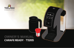
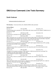
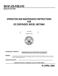
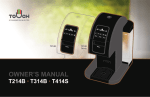
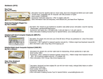
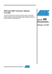
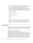
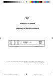
Final Report – Senior Design 2013 Cao, Hill, Lau, Yee 1 TAKtile Shuwen Cao (EE), Timothy Hill (EE), Melissa Lau (EE/CSE), and Andy Yee(CSE) Department of Electrical and Computer Engineering Senior Design Project 2013 Abstract— TAKtile, or a Touch Acquisition Keyboard is a technology which incorporates the touch sensing capabilities of a standard trackpad found on most laptops with a standard mechanical-action keyboard. The purpose of this device is to integrate these two main inputs to a computer into efficient input which allows the user to keep his hands in one position while being able to use the keyboard and mouse input on a standard PC. The device will utilize capacitive touch sensing to detect touch input. Several sensors will sit on the surface on the most frequently used keys of a standard keyboard, and all the sensors on every key will together function as one trackpad. I. click below the spacebar. As can be seen in Figure 1, the Zenith, or ZDS Z-Star EX keyboard, the J-mouse is uniquely identified with a picture of a mouse and an indented circle, so it can be identified visually and physically from the other keys on the keyboard. The left picture is an example of the left and right mouse buttons found on the laptop. Because of its difficulty to use and better technologies that were later introduced, this mouse is no longer used [7]. INTRODUCTION IN today’s world, there are many kinds of computer input devices that make our life much more comfortable, productive and easier. There are ergonomic keyboards that allow us to stay comfortable while typing, and prevent strain injuries that are caused by repetitive motion [1]. There are multi-touch mice that allow us to use multiple fingers to zoom, pinch and manipulate objects on screen and interact with our PC [2]. There are touchscreen devices that can detect the presence and location of a touch within the display area. Touchscreen devices are widely used on ATM machines, retail point-of-sale terminals, car navigation systems, medical monitors and industrial control panels; the touchscreen became wildly popular on the handhelds after Apple introduced the iPhone in 2007. These devices typically have a sleek profile and are a particularly effective and efficient form of input which integrates an on-screen touch keyboard [3]. This means developers and users only need to worry about one input device - the screen itself. Despite the innovation of this feature, many people find it easier to type with physical, mechanical-action keys [4][5]; a survey from an online source indicated that nearly 70% either preferred or needed a physical keyboard [6] instead of a virtual keyboard. A present-day solution to this problem is to include both an on-screen touch keyboard option as well as a “slide-out” mechanical-action keyboard on handheld touchscreen devices. However, this adds a lot of bulk, complications, and redundant input options. A. Summary of Existing Solutions The Zenith JMouse is a mouse solution used with older portable computers that utilized the "J" key on the keyboard and commonly had two separate buttons for the left and right- Figure 1. Zenith JMouse & Keyboard Another solution called TrackPoint system was introduced by IBM in 1992. A TrackPoint, also called a pointing stick, is a cursor control device found in IBM ThinkPad notebook computers. It has a replaceable red tip and is located in the middle of the keyboard between the G, H, and B keys. The control buttons are located in front of the keyboard toward the user [8]. The disadvantage of the TrackPoint is that it is a mechanical device with moving parts that may break and require replacement. As the users are generally limited to using their index finger to operate a pointing stick, hand and wrist strain is common when they use the device for hours at a time. Furthermore, the usage of the TrackPoint required the user to exert a direction force to move the cursor. The speed of the cursor is also directly proportional to the amount of pressure exerted by the user. Thus, the user is required to physically accommodate for this factor, which may need to be conditioned over time. A standard mouse peripheral requires less physical conditioning to satisfy the precision of the mouse cursor. Final Report – Senior Design 2013 Figure 2. TrackPoint on an IBM ThinkPad computer Figure 3. Virtual Keyboard One current technology that is popular with touch screens is the on-screen keyboard. Despite the innovation of this feature, many people find it easier to type with physical, mechanicalaction keys. A present-day solution to this problem is to include both an on-screen touch keyboard option as well as a “slide-out” mechanical-action keyboard on handheld touchscreen devices. However, this adds a lot of bulk, complications, and redundant input options. B. TAKtile Mission We aim to take a step towards addressing the commonplace input issues described above by incorporating the benefits of both a touchscreen input and the physical keyboard. We introduce the idea of TAKtile, a Touch Acquisition Keyboard. The concept behind TAKtile is to integrate a multi-touch trackpad and a standard keyboard into one user-input module. This allows the user to have touch functionality, while retaining the physical and mechanical action of a traditional keyboard. TAKtile will also aid in input efficiency, as the users no longer have to move their hands between the keyboard to the mouse or trackpad. With the intention to design a solution that may affect how the user interacts with a personal computer nearly at a daily basis, there are a few responsibilities to be considered. It is our Cao, Hill, Lau, Yee 2 intention to attempt to improve user interaction, but we do not guarantee that this is the definite solution to the existing limitations mentioned above. Our design, if produced, will be categorized into an already existing market, with the possibility of leading to a new standard of user input as with the increasing popularity of virtual multi-touch capabilities. Incorporating the trackpad and keyboard inputs to a single module may also invite future possibilities to user input not discussed in this report. Engineering a product or design is an on-going process in which engineering must “seek, accept, and offer honest criticism of technical work” [9] from both the consumers and the professionals in related fields of work. We must be aware of existing solutions addressing similar issues and limitations in order to learn, adapt, and improve our design. Furthermore, research that offers insight to our design must be appropriately credited to the original authors [10]. C. TAKtile Design Specifications We aim to produce a product with the following physical and usage specifications: 1. The final TAKtile prototype should use a mechanical key action similar to the standard QWERTY keyboard mechanism. Depressed keys should input corresponding letters into the connected operating system. The product should have the same general footprint and number of keys as a standard QWERTY keyboard. 2. The surface of the keys should have an operation similar to a standard trackpad. When a human finger is in contact with the key surfaces and moving across the keyboard, standard cursor tracking should occur within the Operating System (OS), on the screen. 3. While the keyboard is being used, the cursor cannot move while the user’s fingers are hitting the keys to type. 4. The final prototype should be able to take and process multi-touch input from at least two sources, or fingers. 5. Software should interpret multi-touch data and interpret related data to the OS. 6. TAKtile module should be able to connect to a personal computer through a standard input port such as USB. 7. For both mouse and keyboard functionality, there should be no noticeable delay between time of input and time of response on screen. 8. The final TAKtile module should be housed inside a single unit, with one USB cable connecting to the computer. Final Report – Senior Design 2013 II. DESIGN A. Overview TAKtile can be divided into four main components as shown in Figure 4 below. The capacitive sensors will be the human input for mouse interaction. Human input signals from the sensors will be detected by a selected Sensor Controller. The selected Sensor Controller will send signals to the Touch Controller to turn on the trackpad function of TAKtile. Otherwise, the Touch Controller will maintain off and TAKtile will be function as a normal number keypad. The signals both from Touch Controller and keyboard will all go into the USB bus which will ultimately go into the computer. In addition to incorporating mouse and keyboard functionalities, identical to the features of a simple threebutton and standard keyboard, the final design aims to incorporate multi-touch gestures. An increasing popularity for multi-touch capability on both mobile devices and desktop devices (eg. iPhone and Apple Magic Touchpad) suggests that there is an increasing market for multi-touch technology. This technology has the capability to simulate input devices and add additional capabilities that simplify the use of current mouse actions and keyboard shortcuts [11]. Cao, Hill, Lau, Yee 3 2. Three-dimensional field sensing Another type of human interface sensing is threedimensional field sensing, which utilizes a LC resonant “tank” circuit. This type of sensing is commonly employed in theremins, a type of electronic musical instrument. Proximity of a human hand changes the capacitance, thus affecting the oscillation frequency of the circuit [13]. By measuring this change in frequency and using multiple sensor circuits, we can calibrate the sensors to triangulate the spatial position of the user’s hand. Since TAKtile only employs two-dimensional, surface-contact sensing on a flat surface, this technology would be an overly complex and unnecessary form of human interface sensing. 3. Capacitive touch sensing Capacitive touch sensing employs the use of measure the capacitance between two electrodes or between an electrode and ground [14]. Light contact (little to no pressure) between the sensor pad and a human finger results in an altered charge density around the pad. Ultimately, capacitive touch sensing is an ideal technology for TAKtile, as the user would initiate mouse usage by lightly “skimming” his or her finger across the surface of the keyboard, maintaining contact (unlike threedimensional sensing) but not applying pressure (unlike resistive sensing). There are many ways to implement capacitive touch sensing. They all employ the same working principle and general usage, but it is useful to explore different capacitive sensing technologies in order to select the best implementation for our project. Below, a variety of capacitive sensing schemes are briefly outlined. Figure 4. TAKtile Block Diagram B. Summary of Sensing Technologies A requirement of the TAKtile system is that it needs to be able to sense direct human interface, meaning no implements such as gloves or tools must be required on the user’s part for operation. Below several sensing technologies that are available in today’s world are outlined and analyzed with respect to TAKtile’s needs. 1. Resistive touch sensing Resistive touch sensing operates on a principle of pressure detection. Most resistive touch technologies rely on pressure sensors that change resistance when pressure is applied [12]. While this can definitely sense input directly from human interface (e.g. finger pressure), it is not suitable to our project. Since the TAKtile project already uses pressure to detect if a key on the keyboard is pressed (as per normal keyboard use), resistive touch sensing technology would be a poor choice. Quantum QProx Sensor IC. Quantum Research Group, now owned by Atmel, released a family of integrated circuit chips in 2002 that are capable of acquiring an analog sensor reading off a simple dielectric-covered electrode sensing pad and converting it into a digital output [15][16]. While this IC had everything TAKtile needs for the sensing portion, the IC by itself was lacking in our project-specific signal processing needs. Research continued onto programmable microcontrollers with specialized capacitive sensing capabilities. Microchip mTouch Technology. Microchip creates a host of microcontrollers that are capable of using mTouch capacitive sensing technology. The mTouch capable PIC microcontrollers use Charge Time Measurement Unit (CTMU) hardware to precisely measure the capacitance at one of its pins [17]. mTouch technology relies on the sensor pads lying on top of a ground plane. When a human finger comes into contact with the sensor, it introduces a new capacitance that is in parallel with the sensor capacitance. These two capacitances are added up to determine the new capacitance. User testimony indicates that, since mTouch uses a lot of processing power to calculate precise capacitance, operation seems “sluggish” [18] compared to Quantum’s sensing Final Report – Senior Design 2013 schemes. In addition to this, mTouch sensors also require a very large area for the sensing pad to work effectively [19][20]. Since we hope to employ multiple sensors per key for greater tracking resolution, and a single keyboard key has a very small area, mTouch technology would seem to be inadequate to our specifications. Atmel QMatrix. The Atmel/Quantum QMatrix Technology was briefly explored since it has many applications in touchkeyboard interfaces. It also uses less pins because of its “matrix” layout, shown in Fig. 5. Each “X” electrode sends out a unique pulse pattern, and the “Y” electrodes are connected to input pins taking capacitance measurements. The electrodes are covered by a dielectric [21]. When a human finger comes into contact with the dielectric, the electric field created by the charge pulses sent out by the “X” electrodes is altered (See Fig. 6). Depending on how the field is altered, the voltage reading at each “Y” pin is changed and the microcontroller can determine exactly which cross of electrodes was touched based on the altered electric field and pulse pattern. This sensing scheme is not entirely appropriate for the TAKtile project. While QMatrix can reliably and correctly determine which sensor is being touched at each cross section, it is more useful for determining which key is touched on a touch keyboard, for example. Touch keyboards only require the resolution of a little greater than 1 key per square inch, while TAKtile needs much greater precision for mousetracking purposes. QMatrix sensing pads, while being able to be scaled down to the size we need, have a very complicated topology and requires either VERY tiny (on the order of 0402 package size) 0-ohm jumpers or multi-layer PCBs [21]. QMatrix technology is also only available on a limited subset of Atmel AVR microcontrollers [22]. We needed a different technology which employed simple-topology pads and more flexibility. Atmel QTouch. The Atmel QTouch principle, which is a simpler version of QMatrix, seemed to be appropriate for the TAKtile project. Much practical research was done into QTouch. Like QMatrix pins, QTouch pins send out pulses to the sensor electrode pin [23]. These pulses generate a field at the sensor pad. When a human finger comes into contact with the sensor pad, the field changes (see Fig. 7). Taking measurements from that pin will determine exactly how it was changed and thus the microcontroller can tell when a finger is touching the sensor pad. QTouch operation is simple and fast, and the technology is available on a large variety of Atmel AVR microcontrollers. The sensor pads can be as simple as tiny plain electrodes covered by any dielectric with a range of thicknesses, enabling us the freedom to design our own sensor-grid topology as we pleased. QTouch seemed like an ideal touch-sensing solution for TAKtile. However, during practical applications, it was found that the QTouch libraries were very large due to complex signal processing logic [23], and took up a majority of the flash memory space on the smaller AVRs, leaving no room for Cao, Hill, Lau, Yee 4 additional code that is specialized to and needed for our project. In addition, the coding was very cumbersome; up to ten functions needed to be called to configure an AVR pin for QTouch sensing, and the libraries were all closed-source [24]. There is almost no documentation and zero online-community support for QTouch applications, so debugging and trying to find ways around the complex call functions, or even to find out exactly what they did, was difficult if not impossible. Figure 5. Atmel/Quantum QMatrix Layout Figure 6. Atmel/Quantum QMatrix Operation Diagram Final Report – Senior Design 2013 Cao, Hill, Lau, Yee 5 Figure 7. Atmel/Quantum QTouch Operation Diagram Arduino CapSense. The Arduino CapSense library uses a very similar scheme of operation to Atmel’s QTouch technology. Like QTouch sensing pads, CapSense sensor pad consist of very simple electrodes of any size, covered by a dielectric and attached to a pin. With each microcontroller cycle, the electrode is charged, and the discharge time is calculated. If discharge time is greater than 0, there must be a finger in contact, adding capacitance to the end of the pin. Unlike QTouch technology, the libraries are completely opensource and the coding implementation was simple. Figure 8. This sensor acts as one half of a simple plate capacitor: one plate and the dielectric. When a user places his finger on top of the sensor, the user is completing the capacitor by providing the other conducting “plate” and ground plane. Thus a human finger acts as the negative terminal of a plate capacitor. The completed capacitor has a capacitance C . A very large resistor is connected in series with the sensor/capacitor. This setup is a basic RC circuit with time constant RC. By adjusting R, we can tweak the sensitivity of the sensor. The positive side of the plate capacitor is attached to the Sensor Controller. F C. First Prototype: QTouch and Capsense For KITE0, our first prototype, we decided to convert the Arduino CapSense library into C, enabling it to be programmed onto any AVR (see “D. Sensor Controller”). CapSense offered a simpler and more customizable solution to our problems with QTouch. While we will definitely look back into the QTouch libraries and possibly contact Atmel support for help in the future, CapSense seemed to the best solution for TAKtile in the interests of time. We decided each key should have its own microcontroller, dubbed the “sensor controller” or SC. Each SC would feed its digitized sensor data into a larger, more powerful microcontroller, called the “touchpad controller” or TC. In this way, we could employ many, many sensor pads without bogging down the TC with so many little calculations every loop. See the following two sections, “C. Sensor Pad” and “D. Sensor Controller” for principle of operation of our CapSense scheme. 1. Sensor Pad (KITE0) The sensor for KITE0 was a simple conducting pad covered in a thin dielectric. Specific to our project, we used small (0.1” by 0.1”) square-shaped pads on a prototyping board with a wire attached to the underside. For KITE0, each key will have one board, and each board will have four sensors. A piece of clear tape will cover the top of the board. 2. Sensor Controller and CapSense Operation (KITE0) The Sensor Controller, or SC, performs a series of tests on each sensor to determine if there is a finger touching the other side of it; in other words, it tests to see if the “half plate capacitor” formed by the sensor alone is completed by the presence of a finger touching the other side of the dielectric. It does this by detecting whether the sensor has any significant capacitance value. As mentioned above, we decided to use converted CapSense libraries. The microcontroller we chose was from the TinyAVR family. TinyAVRs were the right price, had much lower power usage, had the right amount of pins, and had QTouch capacitive touch channels in case we wanted to switch back to QTouch at a later time. Final Report – Senior Design 2013 Cao, Hill, Lau, Yee 6 Figure 10. Figure 9. Human interaction and capacitive sensing. The SC first switches power on to the sensor, sending out a set amount of volts, and allowing the capacitor to charge up. It then switches the voltage to that pin off, and takes very fast, repeated voltage measurements at that pin. This way, the SC can determine the transient voltage response by tracking the voltage discharged by the capacitor through the resistor [25]. By measuring the change in voltage over a set amount of time, and calculating the current by means of the resistor, we can use the equation i(t) = C dv/dt to determine the capacitance, and thus can determine whether a finger is touching the sensor [26]. Note that we can also determine “how much” of a finger is touching the sensor; if the finger is just barely grazing the sensor, the capacitance will be lower and take a much shorter time to charge up than if the entire pad of the user’s finger was pressed up against the sensor. In reality, we only really need the time it takes for the capacitor to discharge to a predetermined voltage. This predetermined voltage will be whatever threshold is built into the microcontroller that registers as logic 0, which is usually between 35% and 50% of V+. By using this value, we can get a rough idea of “how much” of a finger is touching the sensor. Times of zero or close to zero mean nothing conductive is touching the sensor; shorter times mean a finger is barely grazing that sensor, and longer times mean more of the finger’s area is in contact with a sensor. This provides a very clear way to determine whether a finger is not touching, partially touching, or definitely touching a sensor pad. F Changing the value of the resistor tweaks the time constant, or how fast the capacitor with discharge. The larger the resistor, the longer it will take to discharge and the less sensitive but more robust the sensor; the smaller the resistor, the more sensitive the sensor. If the sensor is too sensitive, it may be able to detect if a user’s finger is hovering over the sensor but not actually touching it, it is better to have very large resistors to extend the time constant as much as possible. On the other hand, if the resistor is way too large, it will take a long time to detect if the sensor is even being pressed, as the SC must wait extra time to detect a definite change in voltage as the capacitor discharges. For the SC, we will be using Atmel’s ATTINY20 microcontroller from their TinyAVR series, which features 12 I/O pins. In our scheme, the SC will be taking measurements from four separate sensor pads. That means there will be four separate “length of time” readings, each having one pin, per SC. Once the SC gathers this information, it will compile it into a useful form. At the moment, we have a logical 1 for “touching or barely touching” and a logical 0 for “not touching.” The SC will then send this data from all four sensor pads out in serial form (SPI) through an output pin to the Touch Controller, which will interpret this data and put it into a form which the computer can recognize as standard mouse inputs. The ATTINY20 is programmable through Atmel’s “Tiny Programming Interface,” or TPI, only. This presented a small problem, as previously we had thought the AVR Dragon programmer, which has ISP and JTAG programming, was capable of programming Atmel’s entire line of AVR microcontrollers. Fortunately we were able to order an MKII programmer, which can program the ATTINY20 with TPI through the Atmel Studio IDE. Final Report – Senior Design 2013 D. Final Prototype: TAKtile Sensor Board For the final prototype, which we dubbed TAKtile, we were able to make some headway on the QTouch libraries and decided to use those, as they proved more responsive and robust. Working with Atmel QTouch support, we were able to successfully redesign our sensors to fit with the QTouch libraries. We designed a small PCB called the “sensor board” which will hold all the hardware for the sensors of each key. The sensor board is a small PCB measuring 1.8 cm square. There are approximately 45 of these in the TAKtile module. One sensor board will sit on each key on a QWERTY keyboard. The sensor boards collectively make up the surface of the trackpad area. There are several components on the sensor board: the sensor pads on the top side and on the underside there are the ATTINY20 microcontroller (called the Sensor Controller) and the PicoBlade molex connectors which connect each sensor board to switchboard. 1. Sensor Pads The first thing we had to do for the switch from CapSense to QTouch was make the sensors larger because of the measuring capacitor values inside the ATTINY20’s. Sensors that are too small (1” x 1” like we had used with the CapSense method) would not be able to acquire reliable touch sensing information. Therefore we did an overhaul of our sensor design. Originally we had a 2x2 grid of sensors for each key, but we found the sensors did not have enough accuracy and were too big. Since the ATTINY20 can support up to five touch channels, we came up with the following design (Figure 6). The sensors are smaller and are shaped in such a way that your finger is always touching at least two sensors. This greatly improves accuracy. Cao, Hill, Lau, Yee 7 The capacitive sensors themselves are a simple conducting pad covered in a thin dielectric - in our case we used Scotch tape. The pads are the copper from a PCB. Like the CapSense method, the sensor acts as one half of a simple plate capacitor - one plate and the dielectric. When a user places his finger on top of the sensor, the user is completing the capacitor by providing the other conducting “plate” and ground plane. Thus a human finger acts as the negative terminal of a plate capacitor. The completed capacitor has a capacitance CF. 2. Sensor Controller The sensor controller (SC) remains the same for the TAKtile implementation. The ATTINY20 microcontroller, which was in fact specially designed for QTouch, supports five touch buttons each with its own internal measuring capacitor. Some QTouch features include Adjacent Key Suppression (AKS), which allows only one sensor to be “touched” at a time, and sensor threshold tweaking (to vary sensitivity, whereas in the CapSense method the sensitivity was tweaked through resistor values). Using these and other values available in the QTouch libraries, we were able to calibrate the sensors in such a way a light touch still activated a sensor, but it was not so sensitive that it would detect a hover as a touch. There was negligible observable latency between touch and response, as well as “lift” (removing your finger from the sensor pad) and response. Other features included a varying range of touch acquisition sensitivity - the microcontroller can report just how “strong” of a touch signal it acquired. For instance, a “1” would indicate a very light touch with the tip of your finger while a “4” might indicate the entire pad being covered by a large area of your finger (“heavier” touch). For basic prototyping purposes, we chose a simple binary method - 0 for being touched, 1 for being not touched. The main role of the SC is to acquire touch information, turn it into this binary 0 and 1 format, and then package the information into a bit string, which will be sent out through SPI to the touch controller. 3. Detailed QTouch Operation The QTouch libraries employ two different “capacitors” per sensor. The first capacitor is the sensor itself - this is a capacitance of unknown value since the value changes depending on the person touching it and the amount of pressure applied to the touch. There is a second capacitor, the measuring capacitor (labeled “Sample capacitor” in Figure 7) that is internal to the ATTINY20 (although it is shown as external in Figure 7). To measure a touch signal, the microcontroller sends out pulses which charges up the sample capacitor. With each pulse, the charge on the sensor is transferred to the measuring capacitor, which has a known capacitance - this way, the charge of the sensor can be measured even if we don’t know its capacitance, through the equation: Figure 11. TAKtile Sensor Pad 1. C = q/V Final Report – Senior Design 2013 Cao, Hill, Lau, Yee 8 Of the measuring capacitor (which has acquired all the voltage of the sensor capacitor). If the charge reaches a certain threshold (set by the user), the SC will acknowledge that that particular sensor is in a “touched” state. If there is no finger present, the sensor of course cannot hold any charge and the sensor will never realize a “touched” state because of this. Figure 14: Top Layer with five sensor pads TABLE I. Item Figure 12. QTouch Operation with ATTINY20 4. Sensor Board Printed Circuit Board The printed circuit boards (PCB) are all designed on Eagle Layout Editor 6.4.0Version. We design a printed circuit board for each key. It is a double-sided PCB. The size is 17.5mm-by-17.5mm, which is a little larger than the actual key size; therefore, there is minimum space between each key. The reason for this is that when the user drag his/her fingers over those keys, the minimum space will make the whole keyboard continuous. Therefore, it will feel more like a trackpad. The PCB design is shown in Figure 8 and Figure 9 below. Figure 13. Bottom Layer with 8-Pin Molex connector and an ATTiny20 PCB PARTS Description Package Value Resistor (R1 to R5) SMT 0402 1K Resistor (R11) SMT 0402 10K ATTiny20 SOIC Molex Connector 53398 E. Communication Protocol Since we are using many microcontrollers, we must have a reliable way for them to communicate with each other. There are three different communication protocols that the SC and TC can use to talk to each other. They are Universal Asynchronous Receiver/Transmitter (UART), Inter-Integrated Circuit (I2C) [27], and Serial Peripheral Interface Bus (SPI). Each of these has several advantages and disadvantages. UART is a simple serial communication protocol which employs only one line for transmit and one for receive [28]. However, it was eliminated as a possible solution early on due to the fact that communication is limited to one other device per UART channel and the devices we are working with have a max of 8 UART channels, while we will have over 50 devices that need to be communicated with. I2C and SPI were looked at in more detail. I2C offers the advantage of communication using only 2 wires on the bus that communicates between the master and slave devices. This would greatly simplify the wiring between the TC and SC’s. The problem occurs because each device must have a unique bus address. This would mean each SC controller would have to be update with a unique address and this and the location of it mapped out carefully. Because of the limitation I2C was not chosen. SPI was chosen as the communication protocol for our project. The disadvantage compared to I2C is an additional clock wire that is common to all devices and the requirement of an additional slave select wire per SC that will act as slaves on the SPI bus [29]. This will require one pin per SC on the TC. This has the advantage of allowing each SC to be batched Final Report – Senior Design 2013 programmed and the port that it is plugged into on the main board determines its address. 1. Serial Peripheral Interface Bus For this project, we are using SPI communication. More precisely, Arduino Due is our master device, and the Atmel ATTiny20s are the slave device. Cao, Hill, Lau, Yee 9 2) Compile the data into a “grid” that will represent the touchpad surface and which areas of the surface are currently being touched 3) Translate the surface and touch information from the grid into cursor movements 4) Send cursor movements to the OS through USB interface. For the TC we chose the Arduino Due. The Due is an ideal choice because it has enough memory and a powerful ARM processor that is robust enough to handle the large array of data seamlessly. Arduino libraries exist to translate data automatically into cursor movements and the Due has native USB capabilities for easy transfer of the cursor data. H. Software & Algorithms Figure 15. Example SPI communication F. Switchboard PCB The switchboard is a large PCB which connects all the sensor boards to the main microcontroller. It will sit beneath the keyboard. The switch board has 45 connectors on the left side, and two Arduino Due on the right side and the size 101mm wide and 375mm long. Figure 16. Top-layer 1. Cursor Movement Algorithms Our prototype used several evolutions of algorithms to control cursor movement. These algorithms were used by the Arduino Due and took the sensor information, placed it into a coordinate system, and extrapolated a cursor heading based on the currently active sensors. The three algorithms used in various stages of TAKtile’s development are described below. A) Singular Sensor Pad Cursor Movement Algorithm (SSP) The most fundamental CMA consists of assigning a single point to each sensor pad. A library containing the relative positions of all points will determine the special relationships between each point. For instance, the library will contain such information as “Key A is to the left of Key B.” When the sensor pad is “activated” (being touched) the TC will enable the corresponding point. It will remember that initial enabled point, then record the next point to be enabled. If the points are adjacent (the finger is dragging, as opposed to being lifted and touched on an entirely different area of the keyboard), the TC will use a simple formula to calculate the direction of the new point relative to the old point and move the cursor in that direction using the Arduino mouse libraries. Figure 17. Bottom-layer G. Touchpad Controller The touchpad controller (TC) is the name for the large microcontroller we will be using to control the entire system. The TC has four responsibilities: 1) Receive the digital sensor data from all SCs through SPI interface. Figure 18. Sensor Pad layout on the keyboard B) Gridded CMA SSP is only accurate if the keys were lined up in a neat grid. Therefore the Gridded CMA is introduced. Instead of a library recording relative positions, a fine grid is overlaid over the keyboard key-map. If one looks at a keyboard, they will observe that horizontal rows line up, but vertical rows are Final Report – Senior Design 2013 staggered from each other. This creates a non-90-degree grid system. Referring to the figure below, with the overlaid grid system, one can see that each sensor pad now takes up not a single point, but many grid units. A library will record which grid coordinates belong to which sensor. With the Gridded CMA, when the sensor pad is activated, all the points in the grid belonging to the activated sensor pad will be enabled. Similar to the SSP algorithm, the TC will also record the next successive pad that was activated. Using these successive enabled points, the direction of finger movement can then be translated to cursor movement using a similar formula to the one used for SSP. Figure 19. Gridded CMA C) Gridded CMA with Gradient Sensor Data (GSD) It is possible for the SC to report a range of capacitive touch strength to the TC. Using an array of bytes for the grid, we can now express a gradient of signal strength in the grid. Using this information, the center point of the gradient (strongest area) is calculated and we can pinpoint a more exact location of the finger on the sensor pad. This algorithm can be used to determine things such as if the finger is on the edge of a sensor pad or in the middle, or right between two adjacent sensor pads. Using the same directional formula, these more exact finger locations can be translated into precise cursor movements. 2. Algorithm Considerations There are several factors to consider in the software program. Since this project will be utilizing an existing keyboard, the software implementation will be focused on creating a mouse protocol and multi-touch gestures. For TAKtile, the Arduino Due can conveniently appear as a generic keyboard and mouse [30]. Utilizing the Arduino API library, there is a selection of functions available for programming: Mouse.begin() Mouse.click() Mouse.end() Mouse.move() Mouse.press() Mouse.release() Mouse.isPressed() Provided with these functions, an algorithm must be Cao, Hill, Lau, Yee 10 written to receive raw data from the SC and interpret the data into Mouse functions. In addition, user input is another difficult factor that must be considered. The algorithm must be able to analyze the signals and predict the action of the user. For example, a user may place a finger between two capacitive sensors, setting these sensors to logical 0, instead of a single sensor, and the user intends to move the cursor. The size of a user’s finger can vary from person to person, requiring calibration or intelligent coding practices; the user may rest more than one finger on the keyboard, with no intention of performing an action. In order for the algorithm to be robust, these factors should be considered. 3. Multi-touch & Gestures The Multi-touch feature is an extension of the touchpad’s capabilities. There are a few resources the implementation will take advantage of. Part of the difficulty of implementing this feature is due to the lack of resources similar or identical to our design. Using a basic search engine, results most commonly showed touchpad-related projects using infrared LEDs, and a simple Graphical User Interface to demonstrate mouse control and User movement with multiple fingers. Other results regarding modifying one’s own multi-touch events were exclusively software-based. Our requirement desired the incorporation actual mouse functionality into the Ubuntu Operating System, instead of an application limited to such actions. Despite this problem, the research and results provided a direction to the design of the multi-touch feature. A basic polling algorithm written in the Arduino Due will determine the number of fingers in contact with the sensors. With two fingers detected, the algorithm will assume a gesture event will be initiated. The next period of polling will sample the final location of the fingers. Each period will send its data to another receiving program, which will interpret the event. A documentation written by Henrik Rydberg [31] has provided a standard multi-touch protocol for devices using Ubuntu, which can be used as a reference. Additionally, an Ubuntu package includes a command, “xev”, which listens to keyboard and mouse events, and generates a real-time report of events to a command-line. This command will be utilized to ensure proper communication between the device and Operating System. Alternatively, it is probable that the Arduino may provide limitations to the multi-touch feature. The Arduino library does not natively provide a multi-touch or gesture library, and it is currently limited to primitive functions which control the cursor movement. It is almost required that code must be written to interpret and detect such gestures. Furthermore, there is also a risk that the Arduino does not follow the standard Operating System protocol for the multi-touch feature (which may also be closed-source, depending on the system). A solution to this is to associate such events, given some multi-touch detection algorithm, to keyboard shortcut or mouse-button actions. For example, a detection of two fingers tapping once on the sensor would Final Report – Senior Design 2013 be associated with a right-click mouse button. The Arduino library is able to send and simulate keyboard and mouse events to the Operating System. However, the Operating System will associate a specific event with a keyboard or mouse event; events may differ among several Operating Systems and some events may not even be supported. These factors must be considered and addressed for such requirement to be universal to all computers. We aim to incorporate gesture events using a maximum of two fingers. Specified physical actions performed by any two fingers of the User can perform an event with certain applications. These events will simplify and eventually become intuitive to the use of the application compared to the event’s manual approach. However, the gestures require the User to be aware and learn how the action is performed; the User is required to read the User’s Manual to reference to these actions designed by the developer. The current multitouch features are listed below: A) Vertical Scrolling The User will drag two fingers vertically in an upwards or downwards motion across the sensors to scroll an application window up or down. The scroll speed will be dependent of the Operating System settings. This is equivalent to left-click and holding the scroll bar on the right side of the application window. The user will not be able to side scroll left or right, if the standard operation is available. B) Alternate Applications The User will drag two fingers horizontally in a leftwards or rightwards motion across the sensors to alternate active applications. This operation is equivalent to pressing keys ALT + TAB on Windows 7 or a three-finger upward vertical motion on Ubuntu 12.10. Each motion will alternate to the following application on the list. C) Right-click A one-time, two-finger tapping motion by the User will perform an equivalent right-click mouse operation. I. Physical Implementation The sensors need to be integrated into the basic keyboard. This required several different processes and several unique challenges. Each sensor board, containing five sensors each is physically mounted onto the top of each key. The keys that will have the sensors are the main numeric and alphanumeric keys. Each key that will have a sensor board applied will have to be custom cut to receive the sensor board and connector that will protrude from the back. Adhesive, probably typical hot glue will be applied on the key and will hold the sensor board in place. The glue will fill all voids between the key and sensor board. Cao, Hill, Lau, Yee 11 The surface of these keys will need to have a finished appearance and allow for the capacitive sensor to operate. To achieve this I chose to use Acrylonitrile Butadiene Styrene (ABS) plastic because it has the desired electrical properties that work with capacitive sensing, a high dielectric constant and low electrical permittivity. ABS plastic also works well with vacuum forming. It will be vacuum formed into the form of the keys. In order to get the shape for this form, we will create a positive image of a finished key out of aluminum metal to the exact specifications of the finished keys. The cap will be cut out of the form and trimmed up, adhesive applied to the sensor and the plastic cap will be pressed on to the key. We will then stencil the appropriate letter or number onto the surface that corresponds to the key the sensor was placed on. The connections between the sensor boards and the switchboard will be completed with eight conductors of stranded thirty gauge wire. The eight conductors are for both the power and signal connections. There were a few different choices for this connection including flat cable or flexible circuit board conductors. A few problems that these choices presented were cost, ordering the flexible cable assemblies would have quickly put us over our budget. We would have to order in large quantities to get cost down to an economical level. Another problem caused by these choices, since we are customizing a pre existing keyboard, there would not be enough room to route these cables through still have an operation keyboard. The hole or cut out that would be required would interfere with the keyboard itself since it has a flexible circuit board that these conductors would go through and this limits the area we can cut through. Using the individual thirty gauge conductors offers reduced cost and physical flexibility so there is minimal interference with key presses, and it can be bundled to fit through a smaller opening in the flexible circuit board of the keyboard. The connectors we chose, Molex Picoblade, which works with the small gauge wire, requires a very small crimp connections on the end of each wire. We had to acquire a special crimping tool to perform the crimping. There will be some broken connections in the keyboard circuit when holes are drilled through the back of the keyboard. This is unavoidable. This will be corrected by the use of a conductive polymer ink to reconnect broken circuits after all the holes are drilled, to maintain full functionality of the original keyboard. The entire keyboard will sit on a box made out a clear acrylic, this will allow for display of the circuitry underneath for visual appeal. Inside the box the switchboard and two Arduinos will be attached to the bottom and the keyboard will Final Report – Senior Design 2013 be mounted above the switchboard with about an inch clearance and allows for the wires coming out from the bottom of the keyboard room to attach to the switchboard. III. PROJECT MANAGEMENT A. Team Responsibilities For TAKtile, each team member is responsible for the following general topics: Shuwen Cao, EE – SPI communication between the sensor control and touch controller, PCB designs of key sensors and the main switch-board, and housing. Tim Hill, EE – Physical connection of key sensors and keyboard housing. Melissa Lau, EE/CSE – Sensor controller design and touch controller programming. Andy Yee, CSE – Gesture features, and OS/Ubuntu integration. B. Team Communication Our group usually has two distinct meetings every week. We have a scheduled meeting as a group on Monday afternoons to briefly talk about things we have done over the previous week, problems we encounter in the past week, or confusions that will need to be addressed to Prof. Anderson. The second is usually the biggest meeting with our advisor, Prof. Anderson at 3:00pm every Tuesday, discussing about our progress and problems. Our advisor offered us feedback and suggestions on our overall progress, as well as crucial information for our next Design Reviews. Additionally during this semester, we have allotted two time slots for everyone to work together as a team from 6:00pm to 8:00pm on Mondays and Tuesdays. We utilize Google Drive to share and store documents and sources with each other. Also, we created a Google Calendar for SDP and shared our basic individual schedules as a reference, so that we can see what time slot works for everyone when we want to schedule a meeting outside of our normal time slots. We also communicate with each other by email, text messaging, and telephony, and Skype. Team Manager, Tim Hill, was the main contact between the team members and faculty panel to schedule a Design Review presentation appointment. C. Team Multidisciplinary We find it helpful to dedicate several minutes summarizing our discussions and clarifying what has been decided in the meeting. By updating status of our project, we ensure every team member is on the same page. Each team member can offer valuable suggestions to the progress of the individual. We have also exchanged assistance from other team members, who had helped us resolve some problems. By helping others individual team member enhance their professional skills and knowledge. Cao, Hill, Lau, Yee 12 Long-term solutions included exchanging both an overall schedule and weekly schedule of individual tasks. This promoted awareness of each person’s current task and responsibility. Furthermore, it tells each member an estimation of how long a small or large task is needed to be completed based on the individual’s skill set, as well as the general progression relative to the overall timeline. Each member’s tasks and responsibilities are designated by the assigned topics. Each team member’s topic pertains to a crucial component of the final design of TAKtile. Tim’s main task was to design, implement, and build the physical layout of the prototype; such tasks included how sensors were placed on the keyboard, modifying the keyboard chassis and internal components to connect the sensors to the touch controller below while maintaining the circuitry of the keyboard, and building an external chassis to house the touch controller. Shuwen was primarily responsible for establishing SPI communication among multiple ATTINY20s and an Arduino Due. Melissa’s primary task was to design, develop, and implement an algorithm that simulates a consumer trackpad based on user input. Andy was responsible for researching and implementing multi-gesture functionality based on existing software solutions. Despite having separate, individual responsibilities, each task were dependent on the progress of another member’s task. Shuwen’s SPI implementation was crucial to Melissa’s touch controller programming due to the need of integrating multiple ATTINY20 microcontrollers with an Arduino Due. Multi-touch and gesture algorithms developed by Andy depended on the reliability and of Melissa’s algorithm in order to ensure accurate and precise actions and events. The physical housing was also crucial to the entire development and completion of the prototype. Software testing of the physical prototype was also required to ensure the quality and functionality of the design was maintained. D. Life-Long Learning: Engineering Tools, Techniques and Skills General skill required basic to intermediate knowledge in the C/C++ language. In order to program the Atmel chip and implement the communication between two microcontrollers, we have learned to use AVR Studio 6 along with the AVRISP MKII and AVR Dragon programmers. We have learned these hands-on experiences by reading datasheets, manuals and studying tutorials. Alongside these programming tools, we have learned to use all the different programming interfaces that Atmel offers, specifically ISP, JTAG, and TPI. A lot of research was done on the Arduino libraries and infrastructure by visiting their official websites and discussing our confusions with other experienced people on forums, in order to extract the original AVR-GCC code from the CapSense library. In order to get a clean and neat PCB we have learned to use the Easily Applicable Graphical Layout Editor (EAGLE) PCB Design software by following tutorials on the website step by step. Education and self-learning is a lifetime experience. We indeed learned the above skills within this Final Report – Senior Design 2013 semester, but during this time, we actually learned how to find resource we need, how to resolve problems we encountered and how to self-educated and self-learning every day. IV. CONCLUSION A. Final Deliverables For FPR, we will demonstrate TAKtile which will be the final product with the basic trackpad functionality (cursor operations) and keyboard functionality. TAKtile will have 45 keys from the standard keyboard which have the ability to distinguish keyboard and touch action based on user's actions. We will solder everything on the PCB for the full scale of our project and test the basic trackpad functionality of the PCB. Then, we will incorporate multi-touch features into TAKtile such as two-finger scroll, “click-and-drag”, and highlight text into the full-scale keyboard. Last, we will troubleshoot and also make our final TAKtile neat and compact. V. ACKNOWLEDGEMENT We would like to express our gratitude to all those who gave us the possibility to complete this project. We want to thank the UMass Electrical and Computer Engineering Department for giving us this opportunity to do this project in the first instance, to do the necessary research work and to use departmental equipment. We have furthermore to thank Professor Christopher Salthouse and Professor Christopher Hollot for their great lectures and support. We are also deeply indebted to our advisor Professor Neal Anderson whose help, stimulating suggestions and encouragement helped us all the time. REFERENCES [1] [2] [3] [4] [5] [6] [7] S. Hobday. (1988, June). A Keyboard to Increase Productivity and Reduce Postural Stress. [Online]. Available: http://www.maltron.com/keyboard-info/academic-papers/234-akeyboard-to-increase-productivity-and-reduce-postural-stress.html Apple Inc. (2013). Use your fingers to use your Mac in OSX Mountain Lion [Online]. Available: http://www.apple.com/osx/whatis/gestures.html L. Grossman. (2007, Nov. 1). Invention Of the Year: The iPhone [Online]. Available: http://www.time.com/time/specials/2007/article/0,28804,1677329_1678 542_1677891,00.html C. Bunton. (2011, Nov. 17). Will virtual keyboards ever be as good as a physical QWERTY? [Online]. Available: http://www.todaysiphone.com/2011/11/will-virtual-keyboards-ever-beas-good-as-a-physical-qwerty/ J. McKinlay. (2012, Jun. 18). 10 Reasons Why I Like Physical Keyboards over Virtual Keyboards [Online]. Available: http://www.lockergnome.com/hardware/2012/06/18/ten-reasons-why-ilike-physical-keyboards-virtual-keyboards/ C. Mohr. (2011, Jul. 21). Poll: Physical or Virtual Keyboard? [Online]. Available: http://www.wonderoftech.com/poll-physical-or-virtualkeyboard/ Computer Hope. (2012, April 26). JMouse [Online]. Available: http://www.computerhope.com/jargon/j/jmouse.htm Cao, Hill, Lau, Yee [8] [9] [10] [11] [12] [13] [14] [15] [16] [17] [18] [19] [20] [21] [22] [23] [24] [25] [26] [27] [28] [29] [30] 13 TechTarget. (2011, March) TrackPoint(pointing stick) [Online]. Available: http://whatis.techtarget.com/definition/TrackPoint-pointingstick IEEE. (2012, Dec. 10). IEEE - IEEE Code of Ethics [Online]. Available: http://www.ieee.org/about/corporate/governance/p7-8.html ACM. (2012, Dec. 10). Code of Ethics - Association for Computing Machinery [Online]. Available: http://www.acm.org/about/code-ofethics/#sect1 P. Lindeman. (2010, Oct. 27). A Short Report on Multi-Touch User Interfaces [Online]. Available: http://www.medien.ifi.lmu.de/lehre/ws1011/mmi2/mmi2_uebungsblatt1 _loesung_lindemann.pdf R. Downs. (2005). Using resistive touch interface for human/machine interaction [Online]. Available: http://www.ti.com/lit/an/slyt209a/slyt209a.pdf J. Smith. (1999). Electric Field Imaging [Online]. Available: http://sensor.cs.washington.edu/pubs/phd.pdf M. Lee. (2006, March 1). The art of capacitive touch sensing [Online]. Available: http://www.eetimes.com/design/analogdesign/4009622/The-art-of-capacitive-touch-sensing Anonymous. (2004). Capacitive touch sensing [Online]. Available: http://projects.dimension-x.net/archives/111 Quantum Research Group. (2002). QProx QT160/QT161 6-Key ChargeTransfer QTouch Sensor IC Datasheet [Online]. Available: http://www.komponenten.es.aau.dk/fileadmin/komponenten/Data_Sheet /Sensorer/QT160.pdf Microchip Technology, Inc. (2010). Overview of Charge Time Measurement Unit (CTMU) [Online]. Available: http://www.microchip.com/stellent/groups/SiteComm_sg/documents/De viceDoc/en542792.pdf Anonymous. (2012, March 27). Discussion: mTouch vs QTouch capacitive sensing [Online]. Available: http://www.microchip.com.edgekey.net/forums/m609743-print.aspx Microchip Technology, Inc. (2010). Application Note: 3-Channel Capacitive Touch Sensor with 3 LED Drivers [Online]. Available: http://ww1.microchip.com/downloads/en/DeviceDoc/CAP1133.pdf Microchip Technology, Inc. (2010). PIC18F47J13 Family Microcontroller Datasheet [Online]. Available: http://ww1.microchip.com/downloads/en/DeviceDoc/39974A.pdf Quantum Research Group. QMatrix Technologer White Paper [Online]. Available: http://www.atmel.com/Images/qmatrix_white_paper_100.pdf Atmel Corporation. (2009, June). Atmel QTouch Library User Guide [Online]. Available: http://www.dragonwake.com/download/atmel%20touch/attouch.pdf MSC: Micocomputers, Systems, Components. (2010) Atmel QTouch Technology: Product Overview 2012 [Online]. Available: http://www.msc-ge.com/en/5717www/version/default/part/AttachmentData/data/viii-6_2010-gbed5115.pdf Atmel Corportation. (2010, August). Application Note - QTAN0062 [Online]. Available: http://www.atmel.com/Images/qtan0062.pdf P. Badger. Capacitive Sensing Library [Online]. Available: http://arduino.cc/playground/Main/CapacitiveSensor?from=Main.CapSe nse T. Nylund. (2012, May 8). Capacitive Touch Sensing with AVR [Online]. Available: http://tuomasnylund.fi/drupal6/content/capacitivetouch-sensing-avr-and-single-adc-pin I2C Bus. (2012, Sept. 7) I2C-Bus: What's that? [Online]. Available: http://www.i2c-bus.org/ (2012). Interface - UART - PC16550D - TI.com [Online]. Available: http://www.ti.com/product/p16550d Wikipedia contributors (2012). Serial Peripheral Interface Bus [Online]. http://en.wikipedia.org/w/index.php?title=Serial_Peripheral_Interface_B us&oldid=527393391 (2012, Dec. 10). Arduino – MouseKeyboard [Online]. Available: http://arduino.cc/en/Reference/MouseKeyboard Final Report – Senior Design 2013 [31] H.Rydberg. (2012) Multi-touch (MT) Protocol [Online]. Available: https://www.kernel.org/doc/Documentation/input/multi-touchprotocol.txt Cao, Hill, Lau, Yee 14