1
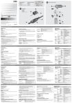
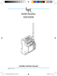
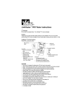
JetNet 6710G / 6810G Series Industrial 8-Port PoE plus 2 Gigabit-TX Managed Etherenet Switch Quick Installation Guide V1.0 www.korenix.com 1. Overview The JetNet 6710G/6810G series are Managed Industrial Power over Ethernet Switches, equipped with eight 10/100 TX ports with 15.4 watts PoE injector and dual 10/100/1000 TX ports for uplink connection. By software configuration or by LLDP auto detection, the eight 10/100 TX PoE injector ports of JetNet 6710G series can deliver 15.4W by IEEE 802.3af or 30W by the latest High Power PoE IEEE 802.3at standard for supporting High Power Requiring Devices (PD). Besides, the eight IEEE 802.3af PoE injector ports of JetNet 6810G series are designed with the Korenix patented Booster PoE technology, which allows the switches to adopt 24~57VDC input and deliver 15.4W per port at 48V for applications where DC 48V power supply is not available. The 2 Gigabit Ethernet ports can provide high speed uplink connectivity to higher level backbone switches with Korenix MSR TM network redundancy technology, which can recover any failure in less than 5milliseconds. To work under vibration and shock environments, the switches are designed with industrial D-coded M12 connectors or rugged RJ45 connectors to ensure exceptional solid Ethernet and PoE connections. 1-1 Packing List Checking The JetNet 6000G series is shipped with the following items. If any of these items is missing or damaged, please contact your customer service representative for assistance. JetNet 6710G Managed High Power IEEE 802.3at PoE Switch (M12 / Rugged RJ) JetNet 6710G-M12 JetNet 6710G-RJ 1 1 JetNet 6810 Managed Booster PoE Switch ( M12 / Rugged RJ) JetNet 6810G-M12 JetNet 6810G-M12 1 1 1 1 M12 on DB9 Shielded Console Cable 1 Rugged M12 D-coded 4-pole Field Assemble able Connecter 8 8 Rugged M12 A-coded 8-pole Field Assemble able Connector 2 2 Rugged RJ45 Field Assemble able Connecter 1 10 10 2 Wall-Mount kits & 8 Screws 1 1 1 1 Quick Installation Guide 1 1 1 1 Documentation and Software CD-ROM 1 1 1 1 1-2 Introduction to the Manual The following manuals are included as PDF files on the CD-ROM: 4Quick Installation Guide: includes information on installing all versions of JetNet 6710G / 6810G series PoE Switch 4User manual – Configuration: applied to the managed versions of JetNet 6710G/ 6810G series PoE Switch 2. Appearances LED: Power, PoE Status, Port Status, Alarm, System Status, Ring Status LED: Power, PoE Status, Port Status, Alarm, System Status, Ring Status Redundant Power Input Redundant Power Input Console Port Alarm Output Console Port Alarm Output 8x10/100 Base-TX PoE 2x1000 Base-T M12 D-coding M12 A-coding 8x10/100 Base-TX PoE 2x1000 Base-T M12 D-coding M12 A-coding JetNet 6710G-M12 JetNet 6710G-RJ 3. Hardware Installation 3-1 Powering of the system The Power input port is located at the top of the front panel and supports redundant input function via a proprietary assembly capable IP-67 connector (CDG-L207SA) included in the shipment. If you cannot find this power connector, please contact your local distributor. For the available input power range and recommended cable size, please refer to the below table. Power Input (DC Voltage) Minimum Maximum Recommended JetNet 6710G-M12 48 60 JetNet 6710G-RJ 48 JetNet 6810G-M12 JetNet 6810G-RJ Input Conductor Cable Size Redundant Input AWG No. / Cable Area (mm2) 48 V1, V2 AWG 14 / 2.0 60 48 V1, V2 AWG 14 / 2.0 22 60 24 V1, V2 bind together AWG 14 / 2.0 22 60 24 V1, V2 bind together AWG 14 / 2.0 The JetNet 6810G only supports single power input that binds V1 and V2 together to obtain higher current for the booster. Use the UL listed Switching power supply to power the JetNet Switch. For the power wiring method, please refer to the figures 3.1-1 and 3.1-2. For system safety and the anti-immunity ability, the chassis ground screw should be well grounded to the earth ground. Note: E.G: Earth Grounding Figure 3.1-1. Power Supply wiring architecture Figure 3.1-2 Power connector assembly diagram 3.2 RS-232 console and Relay Output Connection The RS-232 console and the alarm relay are connected via the assembly type of 5-pole M12 A-coding connector included in the supplied package of JetNet switch. The following figure 3-2-1 is the disassembly diagram of M12 A-coding connector. In the M12 connector packing, the parts 1, 2, 3 are already assembled. Follow the steps for soldering and assembling the cable and connector together: M12 disassembly connector Figure 3.2-1 Field Assemble Step -1: Slide component 4, 5, 6 and then 7 over the console cable. Keep them loose. Do not tighten them yet. 2 cable glands are provided for cable diameter from 3.5 to 5.8 mm. Choose the one that best fits the cable. Step-2: Solder the conductors with the copper wires according to the pin assignment. The soldering side view of the pin is shown as below: Console port pin assignment Step-3: Fasten the components 4, 5, 6 and 7 in sequence. Be sure the gasket is on the right position. See the below M12 assembly diagram: 1. Assembly part 1 and 4, ensure the solder pins are protected by part 4-gasket, then locking part 1 and 5. 2. Insert part 6-seal into part 5. 3. Locking part 5 and 7. 4. Finalized 3.3 Assembly of Ethernet Patch Cables You can connect terminal devices and other segments via twisted pair cables. Ports which are not assigned should be closed with the covering caps contained in the package list of delivery to guarantee the connector is clear without rust. Never install or work on/with the equipment or the ! cabling during the period of its lightning activity. 3.3.1 Assembly of M12 Ethernet Connector For Fast Ethernet M12 D-Code to M12 D-Code connection, you can use either version below: M12-to-M12 Ethernet Cable Wiring For Fast Ethernet M12 D-Code to RJ45 connection, the pin assignment of the patch cable is shown below: M12-to-RJ45 Ethernet Cable Wiring For Gigabit Ethernet M12 A-Code to RJ45 connection, the pin assignment of the patch cable is shown below: M12-to-RJ45 Ethernet Cable Wiring Gigabit M12-to-RJ45 Ethernet Cable Wiring 3.3.2. Assembly of Rugged RJ45 Connector The RJ version provides robust connection by the field assembly capable rugged RJ45 connector. Each component of the connector is shown below: 3.3.2-1 Rugged RJ45 Connecter Components Follow the steps to assemble the rugged RJ45 connector: M12-to-RJ45 Ethernet Cable Wiring Following picture-19 shows the color code of Cat.-5E UTP/STP cable based on the two standards released by TIA/EIA – 568A and 568B. The 568B wiring is by far, the most common wiring method. You can choose the method that suits your application; but ensure that both ends of the cable use the same standard. RJ45 Cable color code 3.4 Wall /Panel Mounting Installation The JetNet 6710G/6810G series are shipped with 1 set mounting bracket which allows users to install JetNet 6710G/6810G on the panel or wall. Assemble the brackets on the rear side of JetNet 6710G/6810G body, then using a suitable screw install onto wall / panel of cabinet with good heat dissipation. 4. Device Management JetNet 6710G / 6810G series switches provide both in-band and out-band configuration methods. You can configure the switch via the RS232 console with the attached console cable, or you can remotely manage the switch via network using Telnet/SSH, Web/HTTPS management. 4.1 Preparation for console management Attach the RS-232 DB9 connector to your PC’s COM port. Connect the M12 A-code 5-pin connector to the console port of the JetNet 6710G/6810G. 4.1.1 Go to Start -> Program -> Accessories -> Communication -> Hyper Terminal 4.1.2 Give a name to the new console connection to create a new serial communication session. 4.1.3 Choose the COM name, and select the correct serial settings. The serial settings of JetNet 6710G/6810G are as below: Baud Rate: 9600 / Parity check: None / Data Bit: 8 / Stop Bit: 1 4.1.4 After connected, you can see Switch login request. Type-in the username and password to login. The default username is “admin”, password is “admin” for console interface. 4.1.5 Follow the manual to configure the device features. 4.2 Preparation for Web management Before you attempt to use the embedded web interface to manage switch operation, verify that your JetNet switch is properly installed on your network and that every PC on this network can access the switch via the web browser. 4.2.1 Launch the web browser (Internet Explorer or Mozilla Firefox) on the PC. 4.2.2 Type http:// 6710G_IP_Address or 6810G_IP_Address (The default IP address is 192.168.10.1.), then press Enter. 4.2.3 The login screen will appear next. Type-in the user name and the password. The default user name and password is admin/admin. 4.2.4 Click OK, and then the welcome page of the web-based management interface will appear. At the left column of the Web management interface are listed the available software features; by pressing the ring column you can also view the detailed configuration interface. For more detailed management features please refer to the software’s users’ manual. The software user manual can be downloaded from Korenix Website as below: http://www.korenix.com/downloads.htm 1. ὖ㽕 JetNet 6710G/6810G㋏߫ᰃϔℒ㔥ㅵൟPoEҹ㔥Ѹᤶᴎˈ䜡᳝8Ͼৃᦤկ30W/15.4Wⱘ 10/100 TX PoEկ⬉ッষ2ϾगܚϞ㘨㔥ষDŽ 䗮䖛䕃ӊ䆒㕂LLDP㞾ࡼẔ㋶ࡳ㛑ˈJetNet 6710G㋏߫ⱘ8Ͼ10/100 TX PoEկ⬉ッষৃҹᦤ կ⒵䎇IEEE 802.3afᷛⱘޚ15.4W⬉䞣䕧ߎˈҹঞ⒵䎇IEEE 802.3atᷛⱘޚ30W催⬉䞣䕧ߎDŽ ℸˈJetNet 6810G㋏߫䜡ⱘ8Ͼ⒵䎇IEEE 802.3afᷛⱘޚկ⬉ッষˈᬃᣕ⾥⋯⧚ᗱPoEछ य़ϧ߽ᡔᴃDŽѸᤶᴎ㮝⬅ℸᡔᴃܕ䆌24~57VDC⬉⑤䕧ܹ㣗ೈˈैᦤկ48V⬉⑤䕧ߎঞ15.4W ⬉䞣䕧ߎDŽ䗖⫼Ѣᴎ఼䆒䳔㽕48V⬉⑤䕧ܹˈै⦄എᅝ㺙䰤ࠊ᮴ᦤկ48Vⱘᑨ⫼DŽ2Ͼ गܚҹ㔥ষᦤկ催䗳Ϟ㘨䗮䘧ˈ䖲⒵䎇Korenix MSR TM ϧ߽ݫԭᡔᴃⱘ催ሖЏᑆѸᤶᴎDŽ TM Korenix MSR ᡔᴃৃҹ5msПݙ໘⧚㔥㒰Ёᮁᘶ䗮䆃DŽᣕ㓁ᤃࡼ⦃ⱘߏކ๗ЁˈѸ ᤶᴎ䜡മⱘᎹϮD-Code M12༈RJ45༈ˈ㛑ᦤկᓖᐌ⠶ⱘҹ㔥PoE䖲DŽ 1-1 ѻક⏙ऩ JetNet 6000G㋏߫ࣙҹϟ⠽કˈབ᳝㔎ᇥ⸈ᤳˈ䇋Ϣկᑨଚ㘨㋏ JetNet 6710G 㔥ㅵൟIEEE802.3at催ࡳ⥛PoE ᎹϮҹ㔥Ѹᤶᴎ (M12 / Rugged RJ) JetNet 6710G-M12 JetNet 6710G-RJ 1 1 JetNet 6810㔥ㅵൟৃछय़PoEҹ㔥Ѹᤶᴎ ( M12 / Rugged RJ) JetNet 6810G-M12 JetNet 6810G-M12 1 1 1 1 M12 on DB9 Shielded Console Cable 1 Rugged M12 D-coded 4-pole Field Assemble able Connecter 8 8 Rugged M12 A-coded 8-pole Field Assemble able Connector 2 2 Rugged RJ45 Field Assemble able Connecter 1 10 10 2Ͼຕᣖᅝ㺙䜡ӊঞ8Ͼ㶎ϱ 1 1 1 1 ᖿ䗳ᅝ㺙ᇐ 1 1 1 1 CD Ⲭܝ 1 1 1 1 CH 1-2 䇈ᯢ᭛ӊ ϟ߫䇈ᯢ᭛ӊˈⱚৃѢCD ݙⲬܝᡒࠄPDF˖ 4ᖿ䗳ᅝ㺙ᇐ˖JetNet 6710G / 6810G ܼ㋏߫PoEѸᤶᴎᅝ㺙ֵᙃ 4⫼᠋˖ݠJetNet 6710G/ 6810G㋏߫PoEѸᤶᴎ䆒㕂ֵᙃ 2. 㾖 LED: Power, PoE Status, Port Status, Alarm, System Status, Ring Status LED: Power, PoE Status, Port Status, Alarm, System Status, Ring Status Redundant Power Input Redundant Power Input Console Port Alarm Output Console Port Alarm Output 8x10/100 Base-TX PoE 2x1000 Base-T M12 D-coding M12 A-coding 8x10/100 Base-TX PoE 2x1000 Base-T M12 D-coding M12 A-coding JetNet 6710G-M12 JetNet 6710G-RJ 3. ⹀ӊᅝ㺙 3-1 կ⬉㋏㒳 ⬉⑤䕧ܹষԡѢࠡ䴶ᵓⱘ乊䚼ˈ䗣䖛ϧ᳝ⱘIP-67䖲఼(CDG-L207SA)ˈᬃᣕݫԭ⬉⑤䕧 ܹDŽℸ䖲఼Ꮖ䱣ᴎ䰘Ϟˈབᵰᙼᡒϡࠄˈ䇋㘨㋏ᔧഄⱘ㒣䫔ଚDŽ݇Ѣ䕧ܹ⬉⑤㣗ೈˈঞᓎ䆂 ⱘ㒓㓚ሎᇌˈ䇋খ㗗ϟ㸼˖ ⬉⑤䕧ܹ (DC ⬉य़) ᇐ㒓䕧ܹ ᳔ᇣ ᳔ ᓎ䆂 JetNet 6710G-M12 48 60 JetNet 6710G-RJ 48 JetNet 6810G-M12 JetNet 6810G-RJ 㒓㓚ሎᇌ ݫԭ䕧ܹ AWG No. / ㎮ᕥ (mm2) 48 V1, V2 AWG 14 / 2.0 60 48 V1, V2 AWG 14 / 2.0 22 60 24 V1, V2 ᑊϔ䍋 AWG 14 / 2.0 22 60 24 V1, V2 ᑊϔ䍋 AWG 14 / 2.0 JetNet 6810G াᬃᣕऩ⬉⑤䕧ܹˈ᠔ҹᇚV1V2⬉⑤ড়ᑊϔ䍋ҹᦤկछय़఼䕗催ⱘ⬉⌕DŽ 䇋Փ⫼䗮䖛UL䅸䆕ⱘ⬉⑤կᑨ఼DŽ⬉⑤䜡㒓䇋খ㗗3.1-1 3.1-2DŽᇚ䆒ഄˈৃҹ⹂ ֱՓ⫼ᅝܼˈᑊৃ䰆ᑆᡄDŽ Note: E.G: Earth Grounding 3.1-1. ⬉⑤䜡ӊᶊᵘ 3.1-2 ⬉⑤䖲఼㺙䜡 3.2 RS-232 console 㒻⬉఼䕧ߎ䖲 RS 232ࠊッষϢ㒻⬉఼䄺䕧ߎষഛ䗮䖛 5-Pole M12 A-coding༈Ϣ䚼Ⳍ䖲DŽℸ䖲༈ Ꮖ䱣ᴎ䰘ϞDŽ3.2-1ᰃℸM12 A-Coding䖲༈ⱘ ᢚौ⼎ᛣDŽ 䱣ᴎ䰘ϞⱘM12䖲༈ˈ1,2,3乍䳊ӊᏆ㒘㺙 ᅠ៤DŽ䇋ᣝ✻ϟ߫ℹ偸ᇚ㒓㓚ঞ䖲༈㒘ড়ϔ 䍋˖ M12 disassembly connector 3.2-1 M12 䖲༈ᢚ㾷⼎ᛣ Step -1: ᇚ4,5,6,7乍䳊ӊ㒘ড়ϔ䍋ˈֱܜᣕᆑᵒˈϡ㽕䫕㋻DŽ2 Ͼ㒓㓚य़Ⲫৃ䗖⫼ѢⳈᕘ㣗ೈЎ3.5mmࠄ5.8mmⱘ㒓㓚DŽ䗝ᢽ᳔䗖 ড়ⱘϔϾՓ⫼DŽ Step-2: ḍ䩜㛮䜡㕂ˈᇚ䪰㒓ঞᇐ㒓 ⛞DŽ䖲 ༈ⱘ䩜㛮䜡㕂⼎ᛣབে˖ Consoleষ䩜㛮ߚ䜡 Step-3: ᇚ4,5,6,7乍䳊ӊձᑣ ᣈ㋻ϔ䍋DŽࡵᖙ⹂䅸ൿ⠛ᰃ ℷ⹂ⱘԡ㕂DŽM12㺙䜡䇈ᯢˈ䇋 খ㗗ে˖ 1. Ꮖ㒘㺙ᅠ៤ⱘᇚ1䚼ߚ( 1,2,3乍䳊ӊ)䎳ൿ⠛(4乍䳊 ӊ)㒘㺙ϔ䍋ˈ⹂ֱൿ⠛ֱᡸ ད䩜㛮ৢˈݡᇚ1䚼ߚϢ5 乍䳊ӊ䫕㋻ 2. ᇚᇕᴵ(6乍䳊ӊ)าܹ5乍 3. ᇚ5乍䳊ӊϢ7乍䳊ӊ 4. ᅠ៤೪ 䳊ӊ 䫕㋻ 3.3 ҹ㔥䏇㒓㒘㺙 Դৃҹ㮝⬅ঠ㒲㒓ᴹ䖲㒜ッ䆒݊ᅗ㔥㒰ऎ↉DŽ≵᳝Փ⫼ⱘッষᑨՓ⫼ッষⲪⲪϞˈҹ⹂ ֱ䖲ッষϡӮ⫳䫜DŽッষⲪᏆ䱣ᴎ䰘ϞDŽ 䇋࣓ᰒ⼎♃䮾⚕ᯊˈᅝ㺙䆒Ꮧ㒓ˈ ! ҹܡ䗴៤䆒䫭䇃DŽ 3.3.1 M12ҹ㔥䖲༈㒘㺙 ݇Ѣᖿ䗳ҹ㔥M12 D-CodeᇍM12 D-Codeⱘ䖲ˈৃҢেϸϾ⠜ᴀ䗝⫼݊ ЁϔϾ˖ M12ᇍM12 ҹ㔥㒓㓚䜡㒓㸼 ݇Ѣᖿ䗳ҹ㔥M12 D-CodeᇍRJ45༈ⱘ䩜 㛮ߚ䜡䏇㒓བে˖ M12ᇍRJ45 ҹ㔥䜡㒓㸼 ݇Ѣगܚҹ㔥M12 A-CodeᇍRJ45䖲ⱘ䩜㛮ߚ䜡䏇㒓ˈ䇋খ㗗ϟ˖ M12-to-RJ45 Ethernet Cable Wiring Gigabit M12-to-RJ45 Ethernet Cable Wiring 3.3.2. RJ45༈㒘㺙 ⬅ѢമⱘRJ45༈ˈѸᤶᴎRJ⠜ᴀᦤկᔎⱘ䖲 㛑DŽ䖲఼ⱘ᠔᳝䳊ӊབে᠔⼎˖ 3.3.2-1 RJ45䖲༈ⱘ䳊ӊ ᣝ✻ℹ偸㒘㺙ℸRJ45༈˖ Step 1. ᇚRJ45㒓㓚ⱘ࠹এ㑺䭓 12mm˗ᓎ䆂Ў24 AWG UPTSTPDŽ Step 4. ᇚᏆ࠹དⱘRJ45㒓㓚こ 䖛㶎ᐑˈO-⦃ˈ䯔ԧ㶎↡ˈЏԧ Step 2. ЏԧϞ㺙Ϟ䯔ԧ㶎↡DŽ Step 3. ᇚO-⦃༫ЏԧϞDŽ Step 5. य़RJ45㒓㓚RJ45༈, 䙉ᕾEIA/TIA 568-Bᷛޚ Step 6. ᇚRJ45༈ᦦЏԧϞˈᑊ⹂ ֱ㶎↡ᆚᇕ M12-to-RJ45 Ethernet Cable Wiring ϟḍTIA/EIA݀ᏗⱘϸϾᷛޚḍTIA/EIA݀ᏗⱘϸϾᷛ – ޚ568A568Bˈᰒ⼎ Cat.-5E UTP/STPⱘ买㡆ҷⷕDŽ568B㒓ᷛޚᰃⳂ᳔ࠡᐌ㾕ⱘ㒓ᮍ⊩DŽԴৃҹḍᑨ ⫼ᴹ䗝ᢽ᳔䗖ড়ⱘᷛˈޚԚ乏⹂ֱ䖲ⱘϸッՓ⫼ⳌৠⱘᷛޚDŽ RJ45 㒓㓚买㡆ҷⷕ 3.4 ຕᣖ/ᬃᶊᅝ㺙 JetNet 6710G/6810G㋏߫䱣ᴎ䜡᳝ᬃᶊ1༫ˈ⫼᠋ৃՓ⫼ᬃᶊᇚJetNet 6710G/6810Gᅝ㺙 䴶ᵓԧϞDŽJetNet 6710G/6810Gᴎԧ㚠ৢ㒘㺙ᬃᶊˈ✊ৢՓ⫼ড়䗖ⱘ㶎ϱᇚ݊ᅝ㺙ࠄ ᬷ⛁㡃དⱘຕ /䴶ᵓϞDŽ 4. 䆒ㅵ⧚ JetNet 6710G / 6810G㋏߫Ѹᤶᴎᬃᣕᏺ(ݙin-band)ঞᏺ(out-band)䆒㕂ᓣDŽ⫼᠋ৃҹ 䗮䖛RS232ࠊッষᇍѸᤶᴎ䖯㸠䆒㕂ˈ䗮䖛㔥㒰䖯㸠䖰ㅵ⧚DŽᙼৃҹ䗝ᢽTelnet/SSH, Web/HTTPS⾡ㅵ⧚⬠䴶DŽ 4.1 Consoleㅵ⧚ⱘޚᎹ ᇚRS-232 DB9༈䖲ࠄPCⱘCOMষˈᇚM12 A-code 5-pin༈䖲ࠄJetNet 6710G/6810GⱘConsoleষDŽ 4.1.1ᓔྟ -> ᑣ -> 䰘ӊ -> 䗮䆃 -> 䍙㑻㒜ッDŽ 4.1.2. Ўᮄ䖲ੑৡDŽ 4.1.3䗝ᢽCOMষˈঞℷ⹂ⱘІষ䆒ᅮDŽJetNet 6710G/6810G ⱘІষখ᭄བϟ˖ ⊶⡍⥛: 9600 / ༛ي᷵偠: None / ᭄ԡ: 8 / ذℶԡ: 1DŽ 4.1.4 䖲ҹৢˈԴӮⳟࠄѸᤶᴎⱘ䇋∖ⱏᔩੑҸDŽ䬂ܹ⫼᠋ৡঞᆚⷕेৃⱏᔩDŽ咬䅸ⱘ⫼ ᠋ৡᰃĀadminā, ᆚⷕᰃĀadmināDŽ 4.1.5ձ⫼᠋᪡ݠ䖯㸠ࡳ㛑䆒ᅮDŽ 4.2 Webㅵ⧚ⱘޚᎹ ޚՓ⫼ݙ㕂ⱘWeb⬠䴶ᇍѸᤶᴎᅲᮑㅵ⧚Пࠡˈ䇋ܜ偠䆕JetNetѸᤶᴎᏆ㒣ℷ⹂ܹ㔥 㒰ˈϨ㔥㒰Ёⱘӏᛣ䅵ㅫᴎ䛑ৃҹ䗮䖛Web⌣㾜఼䆓䯂ѸᤶᴎDŽ 4.2.1ᓔਃ䅵ㅫᴎϞⱘ⌣㾜఼ (IE⌣㾜఼Mozila Firefox)DŽ 4.2.2ഄഔᷣ䬂ܹhttp:// JetNet 6710G/6810G 䆒ⱘIPഄഔ(咬䅸ⱘIPഄഔᰃ 192.168.10.1.)ˈ ✊ৢᣝEnterDŽ 4.2.3ߎ⦄ⱏᔩにষˈ䬂ܹ⫼᠋ৡᆚⷕⱏᔩѸᤶᴎDŽ咬䅸ⱘ⫼᠋ৡᆚⷕᰃadmin/ adminDŽ 4.2.4⚍ߏOK, ߭Ӯߎ⦄webㅵ⧚⬠䴶ⱘЏ义DŽ Webㅵ⧚⬠䴶Ꮊ߫ˈӮ߫ߎ᠔᳝ৃ⫼ⱘ䕃ӊࡳ㛑ˈᇚࡳ㛑乍ሩᓔˈᙼ䖬ৃҹᶹⳟ䆺㒚 ⱘ䜡㕂DŽ 㔥ㅵࡳ㛑ˈ䇋খ㗗⫼᠋䕃ӊݠDŽℸ⫼᠋䕃ӊৃݠѢ⾥⋯⧚ᗱ㔥キϞϟ䕑˖ http://www.korenix.com/downloads.htm 1. Überblick Die JetNet 6710G /6810G Serie sind managebare industrielle Power over Ethernet Switches, ausgestattet mit acht 10/100 TX Ports mit 15.4 Watt PoE Einspeisung und zwei 10/100/1000 TX Ports für Uplink Verbindungen. Über Software Konfiguration oder per LLDP Auto Detection, können die acht 10/100 TX PoE Einspeisungs-Ports der JetNet 6710G Serie entsprechende High Power Requiring Devices (PD) mit je 15.4W gemäß IEEE 802.3af oder mit je 30W gemäß des letzten High Power PoE IEEE 802.3at Standards versorgen. Zusätzlich sind die acht IEEE 802.3af PoE Einspeisungs-Ports der JetNet 6810G Serie mit der Korenix patentierten Booster PoE Technology ausgestattet, womit die Switches den weiten Bereich von 24~57VDC Eingangsspannung akzeptieren und den Anwendungen auch da, 15.4W pro Port bei 48V anbieten können, wo 48VDC nicht verfügbar ist. Die 2 Gigabit Ethernet Ports bieten eine Hochgeschwindigkeits-Uplink Verbindung zu nachgeschalteten Backbone Switches mit Korenix MSRTM Network Redundancy Technology, mittels derer Fehler innerhalb von 5 Mlliseconds überbrückt werden. Für Umgebungen mit Vibration und Stößen sind die Switches mit industriellen D-coded M12 oder robusten RJ45 Verbindungen ausgestattet und gewährleisten damit eine extrem zuverlässige Ethernet und PoE Verbindung. 1-1 Packungsinhalt Die JetNet 6000G Serie wird mit den nachfolgenden Teilen geliefert. Wenn eines der Teile fehlt oder defekt ist, kontaktieren Sie bitte den Kundendienst, der Ihnen gerne weiter helfen wird. JetNet 6710G Managed High Power IEEE 802.3at PoE Switch (M12 / Rugged RJ) JetNet 6710G-M12 JetNet 6710G-RJ 1 1 JetNet 6810 Managed Booster PoE Switch ( M12 / Rugged RJ) JetNet 6810G-M12 JetNet 6810G-M12 1 1 1 1 M12 an DB9 geschirmtes Konsol Kabel Cable 1 Robuster M12 D-codierter 4-pol Feldmontage Verbinder 8 8 Robuster M12 A-codierter 8-pol Feldmontage Verbinder 2 2 1 10 Robuster RJ45 Feldmontage Verbinder 10 2 Wandmontage-Kits & 8 Schrauben 1 1 1 1 Quick Installation Guide 1 1 1 1 Dokumentation und Software CD-ROM 1 1 1 1 DE 1-2 Hinweise zu Handbüchern Die folgenden Handbücher sind als PDF Datei auf der CD-ROM enthalten: 4Quick Installation Guide: Enthält Informationen zur Installation aller Versionen der JetNet 6710G / 6810G Serie PoE Switches. 4Benutzerhandbuch (user manual) – Konfiguration der managebaren Versionen der JetNet 6710G/ 6810G Serie PoE Switches. 2. Ansicht und Abmessungen LED: Power, PoE Status, Port Status, Alarm, System Status, Ring Status LED: Power, PoE Status, Port Status, Alarm, System Status, Ring Status Redundant Power Input Redundant Power Input Console Port Alarm Output Console Port Alarm Output 8x10/100 Base-TX PoE 2x1000 Base-T M12 D-coding M12 A-coding 8x10/100 Base-TX PoE 2x1000 Base-T M12 D-coding M12 A-coding JetNet 6710G-M12 JetNet 6710G-RJ 3. Hardware Installation 3-1 Einschalten des Systems Der Spannungseingangsport befindet sich oben an der Frontseite und bietet redundante Eingänge über eine proprietäre, IP67 geschützte Montage-Verbindung (CDG-L207SA), die der Lieferung beiliegt . Wenn Sie diesen Spannungsversorgungsstecker nicht finden, kontakten Sie bitte Ihren lokalen Händler. Die verfügbaren Eingangsspannungen und empfohlenen Kabelspezifikationen sind in der folgenden Tabelle aufgeführt: Eingangsspannung (DC) Minimum Maximum empfohlen JetNet 6710G-M12 48 60 JetNet 6710G-RJ 48 JetNet 6810G-M12 JetNet 6810G-RJ Eingangskontakt Kabelspezifikation Redundanter Eingang AWG No. / Cable Area (mm2) 48 V1, V2 AWG 14 / 2.0 60 48 V1, V2 AWG 14 / 2.0 22 60 24 V1, V2 beide anschließen AWG 14 / 2.0 22 60 24 V1, V2 beide anschließen AWG 14 / 2.0 Der JetNet 6810G unterstützt lediglich eine Eingangsspannung, bei der beide V1 und V2 angeschlossen werden, um einen höheren Strom für den Booster bereitzustellen. Benutzen Sie UL zertifizierte Netzteile zur Versorgung des JetNet Switch. Die Verdrahtung der Spannungsversorgung zeigen Abb. 3.1-1 und 3.1-2. Zum Systemschutz und zum Schutz vor elektrischen Schlägen sollte das Gehäuse sorgfältig geerdet sein. Note: E.G: Earth Grounding Bild 3.1-1.Verdrahtung der Eingangsspannung igure 3.1-2 Montage des Spannungs-Steckers 3.2 RS-232 Konsole und Anschluss des Relaisausgang Die RS-232 Konsole und das Alarm Relais werden mittels des montierbaren 5-poligen M12 A-coding Steckers verbunden, der im Lieferumfang des JetNet Switch enthalten ist. Die folgende Abb. 3-2-1 zeigt den Aufbau des M12 A-codierten Steckers. Im M12 Stecker Paket sind die Teile 1, 2, 3 schon zusammengebaut. Befolgen Sie diese Schritte für das Löten und Zusammenstecken von Kabel und Stecker M12 disassembly connector Figure 3.2-1 Aufbau des feldmontierbaren M12 Steckers Step -1: Die Teile 4, 5, 6 und dann 7 über das Konsolkabel schieben. Die Teile lose lassen, noch nicht festmachen. Es gibt 2 Kabelanschlüsse für Kabeldurchmesser von 3.5 bis 5.8 mm. Wählen Sie den, der am besten passt. Step-2: Löten Sie die Kupferdrähte an die Kontakte gemäß der Kontaktbelegung. Die Ansicht auf die Kontakte von der Lötseite aus ist hier zu sehen: Konsolport Kontaktbelegung Step-3: Die Teile 4, 5, 6 und 7 in der Reihenfolge festmachen. Achten Sie auf die richtige Position der Dichtung. Unten das Bild zur M12 Montage: 1. Teil 1 und 4 zusammenbauen, die Lötstellen mit der Teil 4 Dichtung abdecken und Teil 1 und 5 verbinden. 2. Teil 6 in Teil 5 stecken. 3. Verschraube Teil 5 und 7. 4. Fertig. 3.3 Montage der Ethernet Patchkabel Sie können Endgeräte oder andere Segmente über paarweise verdrilltes Kabel verbinden. Nicht angeschlossene Ports sollten mit einer im Lieferumfang befindlichen Abschlusskappe verschlossen werden, um vor Rost zu schützen. Arbeiten Sie niemals an Gerät oder Kabeln ! während Gewitter ! 3.3.1 Zusammenbau des M12 Ethernet Verbinders Bei einer Fast Ethernet M12 D-Code auf M12 D-Code Verbindung können Sie eine der u.a. Versionen benutzen: M12-zu-M12 Ethernet Kabel Belegung Bei einer Fast Ethernet M12 D-Code auf RJ45 Verbindung ist die Kontaktbelegung des Patchkabels wie folgt: M12-zu-RJ45 Ethernet Kabel Belegung Für eine Gigabit Ethernet M12 A-Code auf RJ45 Verbindung ist die Kontaktbelegung des Patchkabels wie folgt: M12-to-RJ45 Ethernet Verdrahtung Gigabit M12-zu-RJ45 Ethernet Kabel Belegung 3.3.2. Montage des robusten RJ45 Verbinders Diese RJ Version bietet eine robuste Verbindung mittels des feldmontierbaren robusten RJ45 Verbinders. Alle Teile des Verbinders sind hier zu sehen: 3.3.2-1 robuster RJ45 Verbinder Teile Folgen Sie diesen Schritten zum Zusammenbau des Verbinders Das folgende Bild -19 zeigt die Farbcodes von Cat.-5E UTP/STP Kabel basierend auf den beiden von TIA/EIA herausgegebenen Standards 568A und 568B. Die Verkabelung nach 568B ist die häufigst genutzte Methode. Sie können die Methode selber wählen. Stellen Sie jedoch sicher, daß beide Enden des Kabels nach dem gleichen Standard angeschlossen sind. RJ45 Kabel Farbcodes 3.4 Wand- oder Panel-Montage Die JetNet 6710G/6810G Serie wird mit 1 Set Befestigungshaltern ausgeliefert, mit denen der JetNet 6710G/6810G an einem Panel oder einer Wand montiert werden kann. Montieren Sie die Halterungen für eine guter Wäremeableitung auf die Rückseite des JetNet 6710G/6810G Gehäuses und schrauben Sie sie mit einem geeigneten Schraubendreher an das Panel. 4. Geräte Management JetNet 6710G / 6810G Serie Switches bieten beides in-band und out-band Konfigurationsmethoden. Sie können den Switch via RS232 Konsole mit angeschlossenem Konsolkabel oder Remote über das Netzwerk mittels Telnet/SSH, Web/HTTPS managen. 4.1 Vorbereitung für Konsolmanagement Verbinden Sie den RS-232 DB9 Stecker mit Ihrem PC’s COM Port. Verbinden Sie den M12 A-code 5-pin Stecker mit dem Konsolport des JetNet 6710G/6810G. 4.1.1 Klicken Sie Start -> Programme -> Zubehör -> Kommunikation -> Hyper Terminal 4.1.2 Geben Sie der neuen Konsolverbindung einen Namen und beginnen Sie eine neue serielle Sitzung. 4.1.3 Wählken Sie den COM Port und die korrekten seriellen Einstellungen. Die seriellen Einstellungen des JetNet 6710G/6810G sind wie folgt: Baud Rate: 9600 / Parität: Keine / Daten Bit: 8 / Stop Bit: 1 4.1.4 Nach Verbindungsaufbau sehen Sie die Login Abfrage. Geben Sie Benutzername und Passwort ein. Der Standard Benutzername für die Konsolschnittstelle ist “admin”, das Passwort ist “admin”. 4.1.5 Folgen Sie dem Handbuch um das Gerät zu konfigurieren. 4.2 Vorbereitung für das Web Management Bevor Sie zur Konfiguration des Switches die eingebaute Webseite aufrufen, stellen Sie sicher, daß der Jetnet Switch richtig im Netzwerk installiert ist und jeder PC am Netzwerk den Switch via Web Browser erreichen kann. 4.2.1 Starten Sie den Web Browser (Internet Explorer oderr Mozilla Firefox) am PC. 4.2.2 Geben Sie ein: http:// 6710G_IP_Address oder 6810G_IP_Address (Die Standard IP Addresse ist 192.168.10.1.), dann Enter drücken. 4.2.3 Der Login Bildschirm erscheint. Geben Sie Benutzername und Passwort ein. Standard Benutzername und Passwort ist admin/admin. 4.2.4 Klicken Sie OK und die Welcome Seite der webbasierten Oberfläche erscheint. Auf der linken Seite der Webseite sind die verfügbaren Softwarefunktionen aufgelistet. Ein Klick auf die Ring-Symbole öffnet die detaillierten Konfigurationsseiten. Für weitere detaillierte Management Funktionen schauen Sie bitte ins Benutzerhandbuch (user manual). Das Software Benutzerhandbuch (user manual) kann von der Korenix Website unter diesem Link heruntergeladen werden: http://www.korenix.com/downloads.htm 1. Généralités Les séries JetNet 6710G /6810G sont des switchs ETHERNET Manageable industriels, équipés de 8 ports 10/100 TX ports avec une injection PoE ( Power over Ethernet ) de 15.4W et de 2 ports 10/100/1000 TX ports. Par configuration logicielle, ou par auto détection LLDP, les 8 ports ports PoE 10/100 TX de la série JetNet 6710G series peuvent délivrés 15.4W conformément à la norme IEEE 802.3af ou 30W conformément à la dernière norme Haute Puissance IEEE 802.3at pour supporter les dispositifs haute puissance (PD). De plus, les 8 ports PoE IEEE 802.3af de la série JetNet 6810G sont étudiés avec la technologie « Booster PoE », brevetée par Korenix, qui permet au switch d’êtres alimentés entre 24 et 57 VDC et de délivrer 15.4W sous 48 V par port pour les applications ou une tension d’alimentation 48VDC n’est pas disponible. Les 2 ports Gigabit Ethernet proposent un lien montant haute vitesse vers des switchs de plus haut niveaux avec la technologie de redondance Korenix MSRTM,qui permet de récupérer tous défauts en moins de 5 mS. Afin de permettre une utilisation dans des environnements sévères en termes de chocs et vibrations, les switches sont équippés de connecteurs M12 industriels, ou de connecteurs durçis RJ45. 1-1 Vérification du Colisage La série JetNet 6000G est livrée avec les éléments suivants. Si l’un des ces éléments est manquant ou endommagé, merci de contacter le service client de votre distributeur local. Switch Manageable JetNet 6710G IEEE 802.3at PoE Switch (M12 / Rugged RJ) JetNet 6710G-M12 JetNet 6710G-RJ 1 1 Switch PoE Manageable Booster JetNet 6810 ( M12 / Rugged RJ) JetNet 6810G-M12 JetNet 6810G-M12 1 1 1 1 Cable blindé M12 vers DB9 1 Connecteur durçi M12 D-coded 4-pins assemblable sur site 8 8 Connecteur Durçi M12 A-coded 8-pins assemblable sur site 2 2 1 10 Connecteur RJ 45 durçis 10 2 kits montage mural et 8 vis 1 1 1 1 Guide d’installation rapide 1 1 1 1 Documentation et logiciel sur CD-ROM 1 1 1 1 FR 1-2 Manuels Utilisateurs Les manuels suivants sont inclus en fichiers PDF dans le CD-ROM: 4Guide d’installation rapide: incluant les informations d’installation de toutes les versions de JetNet 6710G / 6810G. 4Manuel Utilisateur 2. Aspects LED: Power, PoE Status, Port Status, Alarm, System Status, Ring Status LED: Power, PoE Status, Port Status, Alarm, System Status, Ring Status Redundant Power Input Redundant Power Input Console Port Alarm Output Console Port Alarm Output 8x10/100 Base-TX PoE 2x1000 Base-T M12 D-coding M12 A-coding 8x10/100 Base-TX PoE 2x1000 Base-T M12 D-coding M12 A-coding JetNet 6710G-M12 JetNet 6710G-RJ 3. Installation Matérielle 3-1 Alimentation du Système L’entrée d’alimentation est située en haut de la face avant, et autorise la redondance d’entrées DC grâce à un câble propriétaire fourni, muni d’un connecteur IP-67 (CDG-L207SA). Les gammes de tension d’entrée, et les tailles recommandées de câbles sont décrites dans le tableau ci-dessous. Entrée Alimentation ( DC ) Minimum Maximum Recommandée JetNet 6710G-M12 48 60 JetNet 6710G-RJ 48 JetNet 6810G-M12 JetNet 6810G-RJ Câblage Entrées Diamètre du câble Entrée Redondante AWG No. / surface(mm2) 48 V1, V2 AWG 14 / 2.0 60 48 V1, V2 AWG 14 / 2.0 22 60 24 V1, V2 reliés ensemble AWG 14 / 2.0 22 60 24 V1, V2 reliés ensemble AWG 14 / 2.0 Le JetNet 6810G supporte uniquement une entrée unique, qui lie V1 et V2 ensemble afin d’obtenir plus de courant disponible pour le booster. Utilisez une alimentation certifiée UL pour alimenter les switchs JetNet. Pour le mode de câblage, référez vous figures 3.1-1 et 3.1-2. Pour la sécurité du systémes et la réduction d’interférences, la vis de terre doit être reliée à une terre électrique correcte. Note: E.G: Earth Grounding Figure 3.1-1. Câblage des alimentations Figure 3.1-2 Assemblage des connecteurs d’alimentation 3.2 Connexions Console RS-232 et sorties Relais La sortie console RS-232 et relais d’alarme sont connectés via le connecteur M12 A-coding 5-pôles à assembler fourni. La figure 3-2-1 est le diagramme de désassemblage du connecteur M12 A-coding. Dans l’emballage du connecteur M12, les parties 1, 2, 3 sont déjà assemblées. Suivez les étapes pour souder et assembler les câbles et connecteur ensemble.: M12 disassembly connector Figure 3.2-1 Diagramme de désassemblage du connecteur M12 Step -1: Glissez les composants 4, 5, 6 et ensuite 7 autour du câble Ne pas encore les serrer. 2 serres câbles sont fournis pour des diamètres de 3.5 à 5.8 mm, choisissez le plus adapté à votre câble. Step-2: Soudez les conducteurs aux câbles conformément à l’assignation des pins. La vue des pins coté soudure est montrée ci-dessous: Assignation des Pins du Câble console Step-3: Serrez les composants 4, 5, 6 et 7 dans l’ordre. Assurez vous que le joint est dans la bonne position. Voir le diagramme d’assemblage ci-dessous : 1. Assembly part 1 and 4, ensure the solder pins are protected by part 4-gasket, then locking part 1 and 5. 2. Insert part 6-seal into part 5. 3. Locking part 5 and 7. 4. Finalized 3.3 Assemblage des câbles ETHERNET Vous pouvez connecter un dispositif ETHERNET via un câble en paires torsadées. Les Ports non utilisés doivent être fermés grâce aux bouchons fournis pour garantir la protection des connecteurs. Ne jamais travaillé ou installé les équipements ! en cas d’activité orageuse. 3.3.1 Assemblage des connecteurs ETHERNET M12 Pour les connexions Fast ETHERNET M12 D-Code vers M12 D-Code, vous pouvez utiliser les deux câblages ci-dessous : M12-to-M12 Ethernet Cable Wiring Pour une connexion ETHERNET M12 D-Code vers RJ45, l’assignation des PINS du câble est la suivante : M12-to-RJ45 Ethernet Cable Wiring Pour la connexion Gigabit Ethernet M12 A-Code vers RJ45, l’assignation des PINS du câble est la suivante : M12-to-RJ45 Ethernet Cable Wiring Câblage ETHERNET Gigabit M12-vers-RJ45 3.3.2. Assemblage du connecteur RJ45 durçi La version RJ permet une connexion robuste grâce aux connecteurs RJ-45 durçis. Chaque composant du connecteur est montré ci-dessous: 3.3.2-1 Composants du connecteur RJ45 durçis Suivez les étapes pour câbler le connecteur RJ 45 durçi: M12-to-RJ45 Ethernet Cable Wiring L’image 19 montre le code des couleurs d’un câble Cat.-5E UTP/STP, basé sur les deux standards TIA/EIA – 568A et 568B. Le câblage 568B est, de loin, la méthode la plus utilisée. Vous pouvez utiliser la méthode la plus adaptée à vos besoins, mais soyez sur que les deux extrémités du câble utilisent le même standard. Code de couleurs du câble 3.4 Montage Mural ou en Panneau Les séries JetNet 6710G/6810G sont livrées avec un jeu d’équerre permettant de les installer sur un panneau ou au mur. Montez les équerres sur la face arrière du châssis JetNet 6710G/6810G, et utilisez les vis convenables pour le fixer au panneau ou en mur en assurant une bonne dissipation thermique. 4. Management du produit Les switchs JetNet 6710G / 6810G peuvent être configurés en local ou à distance. Vous pouvez configurer le switch via la console RS-232 ou via le réseau en utilisant un management Telnet/SSH, Web/HTTPS. 4.1 Préparation le management par console Reliez le câble RS-232C DB- au port COM de votre PC, et connectez le connecteur M12 A-code 5-pin au port console du JetNet 6710G/6810G. 4.1.1 Démarrer -> Programmes -> Accessoires -> Communication -> Hyper Terminal 4.1.2 Donnez un nom à la nouvelle connexion pour créer une nouvelle session de communication. 4.1.3 Choisissez le port COM, et sélectionnez la configuration correcte. La configuration série des JetNet 6710G/6810G est la suivante: Baud Rate: 9600 / Parity check: None / Data Bit: 8 / Stop Bit: 1 4.1.4 Après la connexion, vous devrez entrer un nom d’utilisateur et un mot de passe pour vous connecter. La valeur par défaut est « admin » dans les deux cas. 4.1.5 Suivez le manuel utilisateur pour configurer le produit. 4.2 Préparation pour un Management à distance Avant d’essayer d’utiliser l’interface Web enfoui pour manager le switch, assurez vous que le switch JetNet est correctement installé sur le réseau, et que chaque PC du réseau peut y accéder via un explorateur web. 4.2.1 Lancer l’explorateur web (Internet Explorer ou Mozilla Firefox) sur le PC. 4.2.2 Taper http:// 6710G_IP_Address ou 6810G_IP_Address (l’adresse IP par défaut est 192.168.10.1.), et taper sur « Entrée ». 4.2.3 L’écran de connexion apparait, tapez le nom d’utilisateur et le mot de passe ( par défaut : admin/admin.) 4.2.4 Cliquer sur OK, et la page d’acceuil de l’interface de management par le Web apparaitra. Dans la colonne de gauche, apparait la liste des fonctions logicielles disponible de l’interface de management Web. Pour plus de détails concernant les fonctions de management, référez vous au manuel utilisateur du logiciel, qui peut être téléchargé via le site Web KORENIX : http://www.korenix.com/downloads.htm 1. Información general Las series JetNet 6710G /6810G son Switches Gestionables Industriales Power over Ethernet, equipados con ocho puertos 10/100 TX con inyector PoE de 15.4 watios y dos puertos 10/100/1000 TX para conexión uplink. Mediante configuración de software o por auto detección LLDP, los ocho puertos 10/100 TX con inyector PoE de las series JetNet 6710G pueden ofrecer 15.4W por norma IEEE 802.3af ó 30W por el último standard de PoE de Alta Potencia IEEE 802.3at para poder soportar Dispositivos que requieren Alta Potencia (PD). Además, los ocho puertos IEEE 802.3af con inyector PoE de las series JetNet 6810G están diseñados bajo tecnología Booster PoE, patentada por Korenix, que permite a los switches adoptar alimentación de entrada 24~57VDC y ofrecer 15.4W por puerto a 48V para aplicaciones donde una fuente de 48VDC no esté disponible. Los 2 puertos Gigabit Ethernet pueden proporcionar alta velocidad para la conexión uplink de cara a un nivel más alto de conectividad con los switches de la troncal, mediante la tecnología de red redundante MSRTM, que puede recuperar cualquier fallo en menos de 5 milisegundos. Para poder trabajar en entornos de vibraciones y golpes, los switches están diseñados con conectores industriales D-coded M12 o con RJ45 reforzados para asegurar una excepcionalmente sólida conexión Ethernet y PoE. 1-1 Chequeo de la lista de embalaje Las Series JetNet 6000G se suministran con los siguientes elementos. Si alguno de ellos no aparece o está dañado, por favor contacte con su representante o distribuidor para que le pueda asistir. Switch Gestionable JetNet 6710G de Alta Potencia IEEE 802.3at PoE (M12 / RJ reforzado) JetNet 6710G-M12 JetNet 6710G-RJ 1 1 Switch Gestionable Booster Poe JetNet 6810 ( M12 / RJ reforzado) JetNet 6810G-M12 JetNet 6810G-M12 1 1 1 1 M12 en Cable Consola DB9 Blindado 1 Conector y ensamblaje de campo M12 D-codificado 4-polos reforzado 8 8 Conector y ensamblaje de campo M12 A-codificado 8-polos reforzado 2 2 Conector y ensamblaje de campo RJ45 reforzado 1 10 10 2 kits de montaje en pared & 8 Tornillos 1 1 1 1 Guía Rápida de Instalación 1 1 1 1 Documentación y CD-ROM de Software 1 1 1 1 SP 1-2 Introducción al Manual Los siguientes manuales están incluidos como ficheros PDF en el CD-ROM: 4Guía Rápida de Instalación: Incluye información de la instalación de todas las versiones de las series Switch PoE JetNet 6710G / 6810G 4Manual de Usuario – Configuración. Aplicada a las versiones gestionables de los switches PoE series JetNet 6710G/6810G 2. Apariencia LED: Power, PoE Status, Port Status, Alarm, System Status, Ring Status LED: Power, PoE Status, Port Status, Alarm, System Status, Ring Status Redundant Power Input Redundant Power Input Console Port Alarm Output Console Port Alarm Output 8x10/100 Base-TX PoE 2x1000 Base-T M12 D-coding M12 A-coding 8x10/100 Base-TX PoE 2x1000 Base-T M12 D-coding M12 A-coding JetNet 6710G-M12 JetNet 6710G-RJ 3. Instalación de Hardware 3-1 Alimentación del sistema La entrada de alimentación se localiza en lo alto del panel frontal y soporta la función de entrada redundante mediante un conector propietario IP-67 (CDG-L207SA) incluido en el embalaje. Si no encontrara dicho conector, por favor contacte con su distribuidor. Consulte la siguiente tabla para concretar el rango de entrada disponible y el tamaño recomendado de cable. Entada Alimentación (Tensión DC) Mínimo Máximo Recomendado JetNet 6710G-M12 48 60 JetNet 6710G-RJ 48 JetNet 6810G-M12 JetNet 6810G-RJ Conductor de entrada Tamaño de cable Entrada Redundante AWG No. / Cable Area (mm2) 48 V1, V2 AWG 14 / 2.0 60 48 V1, V2 AWG 14 / 2.0 22 60 24 V1, V2 unidos AWG 14 / 2.0 22 60 24 V1, V2 unidos AWG 14 / 2.0 El JetNet 6810G sólo soporta entrada simple de alimentación, que une V1 y V2 para poder obtener una mayor corriente para el booster. Use una Fuente de Alimentación Conmutada UL para alimentar el Switch JetNet. Consulte las figuras 3.1-1 y 3.1-2 para el cableado de la alimentación. De cara a la seguridad e inmunidad del sistema, el tornillo de tierra del chasis deberá estar lógicamente bien conectado a tierra. Note: E.G: Earth Grounding FiFigura 3.1-1. Conexión de Alimentación Figura 3.1-2 Diagrama de ensamblaje conector 3.2 Consola RS-232 y Conexión de Relé de Salida La consola RS-232 y el relé de alarma se conectan mediante conector de ensamblaje de tipo 5-pole M12 A-coding incluido en el paquete de accesorios suministrado con el switch JetNet. En la figura siguiente 3-2-1 se puede ver el diagrama de desensamblaje del conector M12 A-coding. En el paquete de conectores M12, las partes 1, 2 y 3 están realmente ensambladas. Siga los siguientes pasos para soldar y ensamblar el cable y conector: M12 disassembly connector Figura 3.2-1 Desensamblaje conector de campo M12 Paso-1: Deslice el componente 4, 5, 6 y a continuación el 7, sobre el cable de consola. Manténgalos sueltos. No los apriete aún. Se proporcionan 2 prensaestopas para diámetros de cable de 3,5 a 5,8 mm. Elija el que mejor se ajuste en su caso. Paso-2: Suelde los conductores con los hilos de cobre de acuerdo a la asignación de pines. La vista de los pines para soldar se muestra como sigue: Asignación de pines del puerto de consola Paso-3: Sujete los componentes 4, 5, 6 y 7 en secuencia. Asegúrese de que la junta está en la posición correcta. Véase a continuación el diagrama de montaje: 1. Assembly part 1 and 4, ensure the solder pins are protected by part 4-gasket, then locking part 1 and 5. 2. Insert part 6-seal into part 5. 3. Locking part 5 and 7. 4. Finalized 3.3 Ensamblado de los Cables de Conexión Ethernet Usted puede conectar diversos dispositivos mediante cable de par trenzado. Los puertos no asignados deberán estar tapados con las caperuzas contenidas en el paquete de equipamiento en orden de garantizar la ausencia de suciedad en el conector. Nunca instale o trabaje con el dispositivo o con el cableado ! en momentos de actividad atmosférica tormentosa. 3.3.1 Ensamblado del Conector Ethernet M12 Para conexión Fast Ethernet M12 D-Code a M12 D-Code, usted puede usar cualquiera de los modos siguientes: Cableado Conexión Eth. M12-a-M12 Para conexión Fast Ethernet M12 D-Code a RJ45, la asignación de pines del cable en cuestión se muestra a continuación: Cableado Conexión Eth. M12-a-RJ45 Para conexión Gigabit Ethernet M12 A-Code a RJ45, la asignación de pines del cable en cuestión se muestra a continuación: M12-to-RJ45 Ethernet Cable Wiring Cableado Conexión Eth Gigabit M12-a-RJ45 3.3.2. Ensamblado de Conector RJ45 Reforzado La versión RJ proporciona una robusta conexión para el ensamblaje de campo gracias al conector RJ45 blindado. Cada componente del conector es mostrado a continuación: 3.3.2-1 Componentes Blindados Conector RJ45 Siga los siguientes pasos para ensamblar el conector blindado RJ45: M12-to-RJ45 Ethernet Cable Wiring La siguiente figura nº19 muestra el código de color del cable Cat.-5E UTP/STP basado en los dos estándares publicados por la TIA/EIA (568A y 568B.) El cableado 568B es habitualmente el método más común. Usted puede elegir el método que mejor le vaya a su aplicación, pero asegúrese de que en ambos extremos del cable se use el mismo estándar. Código de Color Cable RJ45 3.4 Instalación de Montaje en Pared /Panel Las series JetNet 6710G/6810G se suministran con 1 conjunto de soportes para montaje que permite a los usuarios instalar el JetNet 6710G/6810G en panel o en pared. Ensamble los soportes en la parte posterior del cuerpo del JetNet 6710G/6810G, después utilizando tornillería y herramienta adecuadas, instálelo en pared o armario de panel que tenga una buena disipación de calor . 4. Gestión del dispositivo Las series switch JetNet 6710G / 6810G proporcionan métodos de configuración tanto en banda como fuera de banda. Usted puede configurar el switch por la consola RS232 mediante el cable de consola adjunto, o puede gestionar el switch via red usando gestión Telnet/SSH, Web/HTTPS. 4.1 Preparación para gestión de consola Conecte el conector RS-232 DB9 al puerto COM de su PC. Conecte el conector M12 A-code 5-pin al puerto de consola del JetNet 6710G/6810G. 4.1.1 Vaya a Start -> Program -> Accessories -> Communication -> Hyper Terminal 4.1.2 Dele un nombre a la nueva conexión de consola para crear una nueva sesión de comunicación 4.1.3 Elija el nombre del COM y ajuste correctamente los parámetros serie. Los parámetros serie del JetNet 6710G/6810G son: Rango de baudios: 9600 / Paridad: No / Bit de datos: 8 / Bit de parada: 1 4.1.4 Después de la conexión, Usted podrá ver la petición de login del Switch. Inserte nombre de usuario y contraseña para entrar. El nombre de usuario por defecto es “admin”; la contraseña es así mismo “admin” 4.1.5 Siga el manual para configurar las características del dispositivo. 4.2 Preparación para gestión Web Antes de intentar empezar a usar el interface web embarcado para gestionar la operación del switch, verifique que el mismo esté correctamente instalado en su red y que todos los PC’s de esa red puedan acceder al switch mediante el navegador web. 4.2.1 Lance el navegador web (Internet Explorer o Mozilla Firefox) en el PC. 4.2.2 Escriba http:// 6710G_IP_Address or 6810G_IP_Address (La dirección IP por defecto es 192.168.10.1.) luego presione Enter. 4.2.3 La pantalla de login aparecerá a continuación. Escriba el nombre de usuario y contraseña, que por defecto son admin/admin. 4.2.4 Clickee OK, y después aparecerá la página de bienvenida del interface de gestión basado en web. En la columna del lado izquierdo del Interface Web están listadas las características disponibles de software; presionando en las mismas sitas en dicho árbol, se puede acceder a la configuración detallada. Para ver las características de gestión más en detalle, por favor acuda al manual de usuario de software, el cual puede ser descargado desde este link de la web de Korenix: http://www.korenix.com/downloads.htm 1. Обзор Серия JetNet 6710G /6810G – это промышленные управляемые коммутаторы с функцией PoE, оборудованные восьмью портами 10/100 TX, мощность PoE составляет 15.4 Вт, и двумя uplink-портами 10/100/1000 TX. Восемь портов 10/100 TX PoE устройств серии JetNet 6710G, программно или автоматически (при помощи LLDP) конфигурируемые, способны передать 15.4Вт, согласно стандарту IEEE 802.3af или 30Вт, согласно последнему стандарту PoE IEEE 802.3at, поддерживающему устройства высокой мощности (PD). Кроме того, восемь портов IEEE 802.3af PoE устройств серии JetNet 6810G были разработаны с применением запатентованной Korenix технологией Booster PoE, позволяющей коммутатор питать напряжением в диапазоне 24~57В (DC), а на портах PoE получать 15.4Вт, 48В в тех задачах, где напряжение 48В (DC) отсутствует. 2 Gigabit Ethernet uplink-порты обеспечивают высокоскоростное соединение с магистральными коммутаторами и поддерживают технологию сетевого резервирования Korenix MSRTM, которая позволяет восстановить любой сбой менее чем 5 миллисекунд. Для работы в тяжелых промышленных условиях, таких как вибрация и удары, коммутаторы имеют промышленные разъемы M12 (D-coded) или защищенные разъемы RJ45 для обеспечения исключительно прочного соединения. 1-1 Содержимое поставляемой упаковки Устройства серии JetNet 6000G поставляются со следующими наименованиями: (Если любое из этих наименований отсутствует или повреждено, обратитесь к представителю сервисного центра за помощью). JetNet 6710G-M12 Управляемый коммутатор JetNet 6710G высокой мощности IEEE 802.3at PoE (M12 / защищенный RJ) 1 JetNet 6710G-RJ Booster PoE ( M12 / защищенный RJ) Защищенный M12 (D-coded) 4-контактный разъем для сборки Защищенный M12 (A-coded) 8-контактный разъем для сборки 1 JetNet 6810G-M12 1 1 1 1 1 Управляемый коммутатор JetNet 6810 с технологией M12 на DB9 экранированный консольный кабель JetNet 6810G-M12 1 8 8 2 2 10 Защищенный RJ45 для сборки 10 2 настенный крепеж и 8 винтов 1 1 1 1 Руководство по быстрой инсталляции 1 1 1 1 1 1 1 1 Компакт-диск с документацией и программным обеспечением RU 1-2 Введение Следующие руководства можно найти в электронном виде (PDF) на компакт-диске: 4Руководство по быстрой инсталляции: включает инструкцию по инсталляции всех версий PoE коммутаторов серий JetNet 6710G и 6810G 4Руководство пользователя – Конфигурирование устройства – для всех версий управляемых PoE коммутаторов серий JetNet 6710G и 6810G 2. Внешний вид и размеры LED: Power, PoE Status, Port Status, Alarm, System Status, Ring Status LED: Power, PoE Status, Port Status, Alarm, System Status, Ring Status Redundant Power Input Redundant Power Input Console Port Alarm Output Console Port Alarm Output 8x10/100 Base-TX PoE 2x1000 Base-T M12 D-coding M12 A-coding 8x10/100 Base-TX PoE 2x1000 Base-T M12 D-coding M12 A-coding JetNet 6710G-M12 JetNet 6710G-RJ 3. Монтаж оборудования 3-1 Система питания Порт входа питания расположен в верхней части передней панели и поддерживает резервирование системы питания при помощи проприетарного разъема IP-67 (CDGL207SA), входящего в комплект поставки. Если Вы не можете найти этот разъем обратитесь к локальному дистрибьютеру за помощью. Допустимые входные напряжения и рекомендуемый размер кабелей показаны в таблице 2. Входное напряжение (DC) Минимум Максимум Рекомендуемое Вход питания Размер кабеля Резервный вход Номер AWG / Площадь сечения (mm2) JetNet 6710G-M12 48 60 48 V1, V2 AWG 14 / 2.0 JetNet 6710G-RJ 48 60 48 V1, V2 AWG 14 / 2.0 JetNet 6810G-M12 22 60 24 V1, V2 объединены AWG 14 / 2.0 JetNet 6810G-RJ 22 60 24 V1, V2 объединены AWG 14 / 2.0 Коммутаторы серии JetNet 6810G поддерживают только нерезервированный вход питания, в связи с этим входа V1 и V2 объединены вместе для большего тока для технологии PoE Booster. Подключение питания необходимо произвести по схеме, показанной на рисунке 3.1-1. Разъем питания показан на рисунке 3.1-2. Для обеспечения безопасности системы и защищенности устройство необходимо правильно заземлить (подключить заземление винтовым соединением к корпусу в обозначенном месте). Рисунок 3.1-1. Схема подключения питания Рисунок 3.1-2 Сборка разъема питания 3.2 Подключение контактов реле и использование консольного кабеля RS-232 К о н с ол ь н ы й к а б ел ь R S - 2 3 2 и в ы х од ы реле подключаются при помощи сборного 5 - к о н та к т н о го р азъ е м а M 1 2 ( A - c o d e d ) , поставляемого вместе с коммутатором. На рисунке 3-2-1 показана схема разъема M12 (A-coded): В разъеме M12, части 1, 2, 3 поставляются собранными. Для того чтобы спаять и собрать кабель и разъем необходимо: Рисунок 3.2-1 Схема разъема M12 Step -1: Надеть последовательно компоненты 4, 5, 6 и 7 на консольный кабель. Оставьте между ними расстояние и не затягивайте. В комплекте идет два уплотнителя для кабелей диаметром от 3.5 до 5.8 мм. Выберите наиболее подходящий. Step-2: Припаяйте провода к соответствующим выводам разъема, согласно рисунку: Схема консольного порта Step-3: Последовательно затяните компоненты 4, 5, 6 и 7. Убедитесь, что уплотнитель находится в правильном положении. Последовательность сборки показана на рисунке 10: 3.3 Сборка соединительного Ethernet кабеля Вы можете соединить терминальные устройства и сегменты при помощи кабелей витой пары. Не используемые порты должны быть закрыты заглушками во избежание их загрязнения. В грозу строго запрещается производить монтаж ! или работать с оборудованием и кабелями. 3.3.1 Сборка Ethernet кабеля с разъемами M12 Для изготовления кабеля с разъемами Fast Ethernet M12 D-Code с одной стороны и M12 D-Code с другой, Вы можете использовать следующий вариант: Схема кабеля с разъемами M12-M12 Для изготовления кабеля с разъемами Fast Ethernet M12 D-Code с одной стороны и RJ45 с другой, необходимо соединить провода так, как показано на рисунке 15: Схема кабеля с разъемами M12-RJ45 Для изготовления кабеля с разъемом Gigabit Ethernet M12 A-Code с одной стороны и RJ45 с другой, необходимо соединить провода следующим образом: M12-to-RJ45 Ethernet Cable Wiring Схема кабеля Gigabit Ethernet с разъемами M12-RJ45 3.3.2. Сборка защищенного разъема RJ45 Защищенная версия разъема RJ45 позволяет быстро и легко подключать и отключать устройства. Каждый компонент разъема показан на рисунке: 3.3.2-1 Компоненты защищенного разъема RJ45 Для сборки разъема RJ45 необходимо: Сборка защищенного разъема RJ45 На рисунке 19 показаны цветовые схемы кабеля категории-5E UTP/STP, основанные на двух стандартах TIA/EIA – 568A и 568B. Наиболее общий метод - 568B. Вы можете выбрать наиболее подходящую схему в зависимости от задачи, но необходимо удостовериться, что начало и конец кабеля подключены с использованием единой схемы. Рисунок 19 Цветовые схемы кабеля RJ45 3.4 Монтаж на стену или панель Коммутаторы серий JetNet 6710G/6810G поставляются с набором крепежа, при помощи которого можно произвести монтаж коммутатора JetNet 6710G/6810G на панель или на стену. Монтаж производится креплением уголков (рисунок 20), входящих в комплект поставки, к задней части коммутатора JetNet 6710G/6810G, затем при помощи подходящих винтов (саморезов) устройство крепится к стене или панели шкафа (шкаф должен хорошо отводить тепло, во избежание перегрева устройства). 4. Управление устройством Коммутаторы серий JetNet 6710G / 6810G могут быть настроены как локально, так и удаленно. Вы можете сконфигурировать устройство при помощи консоли RS232 локально или удаленно, используя Telnet/SSH и Web/HTTPS. 4.1 Подготовка консольного управления Подключите кабель с разъемом RS-232 DB9 к COM-порту Вашего компьютера, а 5-контактный разъем M12 (A-code) к консольному порту коммутатора JetNet 6710G/6810G. 4.1.1. Нажмите Пуск -> Все программы -> Стандартные -> Связь -> Hyper Terminal 4.1.2. Задайте имя подключению. 4.1.3. Выберите COM-порт и следующие параметры подключения: Скорость (бит/с): 9600 / Биты данных: 8 / Четность: Нет / Стоповые биты: 1 4.1.4. При успешном подключении Вы должны увидеть запрос коммутатором имени пользователя, и, после ввода имени пользователя, пароля. Имя пользователя и пароль по умолчанию - “admin”/“admin”. 4.1.5. Для конфигурации устройства обратитесь к соответствующим разделам руководства пользователя. 4.2 Подготовка Web-управления Прежде чем использовать встроенный Web-интерфейс для настройки функций коммутатора, проверьте, что коммутатор JetNet правильно подключен к сети и каждый компьютер сети имеет доступ к коммутатору через Web-браузер. 4.2.1. Запустите Web-браузер (Internet Explorer или Mozilla Firefox) на компьютере. 4.2.2. Введите http:// IP адрес 6710G или IP адрес 6810G (IP адрес по умолчанию 192.168.10.1.), и нажмите Enter. 4.2.3. Затем должно появиться окно аутентификации пользователя. Введите имя пользователя и пароль. Имя пользователя и пароль по умолчанию - admin/admin. 4.2.4. Нажмите OK, и дождитесь появления страницы приветствия Web-конфигурирования. В левой части Web-интерфейса отображены доступные функции и группы функций (нажмите на для того, чтобы развернуть группу) конфигурирования устройства. Для получения более детальной информации по конфигурированию коммутатора используйте руководство пользователя по программному обеспечению, которое может быть загружено с сайта компании Korenix: http://www.korenix.com/downloads.htm Patent No. (Taiwan): Granted Invention: I 321415 Granted Invention: I 313547 Utility Model: M339840 Utility Model: M339841 Ѯᢊடց ี݂ I ี݂ I ཱི M ཱི M 321415!ဴ 313547 ဴ 339841 ဴ 339840 ဴ Tel:+886-2-89111000 Fax:+886-2-29123328 Business service:[email protected] Customer service:[email protected] CPQ000N6710000