1
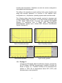
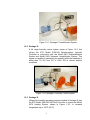
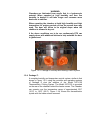
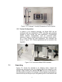
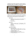
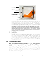
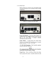
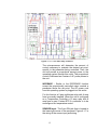
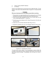
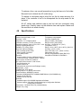
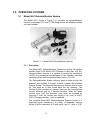
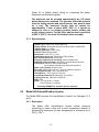
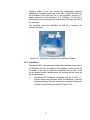
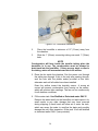
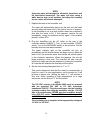
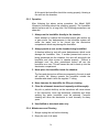
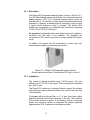
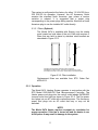
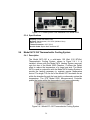
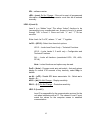
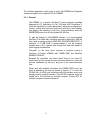
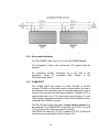
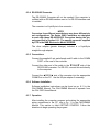
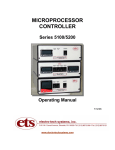
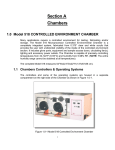
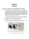
CONTROLLED ENVIRONMENT
CHAMBER
Model 5503-00 & 5503-11
With
Package C, D, E or F
Operating Manual
1/07
www.electrotechsystems.com
TABLE OF CONTENTS
Page
1.0
2.0
3.0
4.0
GENERAL
1
1.1
Basic Chambers
1.1.1 Specifications
1
1
1.2
Standard Packages
1.2.1 Pkg. C
1.2.2 Pkg. D
1.2.3 Pkg. E
1.2.4 Pkg. F
1.2.5 Custom Configurations
2
3
3
4
4
5
1.3
Unpacking
5
CHAMBER
7
2.1
Description
7
2.2
Installation
8
PACKAGE SYSTEMS
8
3.1
Package C
9
3.2
Package D
9
3.3
Package E
9
3.4
Package F
9
CONTROLLER
9
4.1
Description
4.1.1 Model 554 Humidity/ Temperature Sensor
4.1.2 Control Unit
9
9
10
4.2
Installation
4.2.1 Initial Check Out
4.2.2 Set Up
18
18
19
4.3
Operation
4.3.1 Set Point Adjust
4.3.2 Increase
4.3.3 Decrease
20
20
21
21
4.4
Calibration
22
5.0
6.0
7.0
4.5
Maintenance
22
4.6
Specifications
24
OPERATING SYSTEMS
25
5.1
Model 5461 Dehumidification System
5.1.1 Description
5.1.2 Specifications
25
25
26
5.2
Model 5462 Humidification System
5.2.1 Description
5.2.2 Installation
5.2.3 Operation
5.2.4 Maintenance and Cleaning
5.2.5 Specifications
26
26
27
28
30
31
5.3
Model 5474 Heating System
5.3.1 Description
5.3.2 Installation
5.3.3 Operation
5.3.4 Specifications
31
32
32
33
34
5.4
Model 5473-150 Thermoelectric Cooling System
5.4.1 Description
5.4.2 Installation
5.4.3 Operation
5.4.4 Performance
5.4.5 Specifications
34
34
35
35
37
37
5.5
Maintenance
37
PROGRAMMING THE MICROPROCESSOR CONTROLLER 38
6.1
Accessing the Programming Menu
38
6.2
Optimizing Controller Programming
38
6.3
Computer Software (Optional)
6.3.1 General
6.3.2 Set Up & Installation
6.3.3 COMM Port
6.3.4 RS232/485 Converter
6.3.5 Connections
6.3.6 Software Installation
6.3.7 Operation
6.3.8 Logging and Charting
6.3.9 Software Support
46
47
48
48
49
49
49
49
50
50
Warranty
51
1.0 GENERAL
Many applications, such as electronics, medical, pharmaceutical and research
require a controlled environment for testing, assembly or storage. The Model
5503 is designed to meet these requirements. The Model 5503 is available in
standard or custom configurations to meet specific customer requirements.
1.1
Basic Chambers
Model 5503-00:
Model 5503-11:
Enclosure only without glove ports
Enclosure only with 6” (150mm) glove ports
Figure 1.1-1a: Model 5503-00
Figure 1.1-1b: Model 5503-11
1.1.1 Chamber Specifications
Material:
¼” (6mm) clear acrylic
3/8” (9mm) left end cap
Construction:
Wrapped, PS30 welded seams
Door: (left side)
½” (12.7mm) clear acrylic with ½-turn latch
Seal: ¼” (6mm) Poron, non-setting gasket
Gloves: (when configured)
.018” (0.5mm) latex, 6” (14.3cm) ports
Operating Range:
Humidity: <1 – 100%
Temperature: <32 – 135 °F (0-55 °C)
1.2
Access Ports: (left side)
2x¼” (6mm) hose barbs
1x1” (25.4mm) Hose barb
1x½” (12.7mm) compression fitting
1x1½” (31.4mm) cable pass through
Dimensions: 24”Wx18”Dx15”H (61x46x38 cm)
Weight: 27 lbs (12.3 kg)
Standard Packages
The following packages provide solutions to most dehumidification
applications. Each package includes an ETS Series 5000 Microprocessor
Controller plus respective operating systems to control humidity or
1
humidity and temperature. Chambers can also be custom configured to
meet special user requirements.
The ability of the chamber to reach and then hold a given humidity level
along with humidity gradients is a function of the chamber (size,
configuration etc.), temperature, operating systems and controllers used.
The following charts show the time typically required to decrease and
increase humidity (Blue = RH, Red = T °C) plus humidity gradients using
an ETS Model 5200-231-241 Controller with optional CALCOMMS
software in conjunction with a Model 5461 Desiccant/Pump
Dehumidification System and a Model 5462 Ultrasonic Humidification
System (Package D).
Rate of humidity decrease
Rate of humidity increase
Low humidity gradient
High humidity gradient
1.2.1 Package C:
Includes the ETS Model 5462 Humidification System controlled by
the ETS Model 5100-240 Microprocessor Humidity Controller as
shown in Figure 1.2-1. Chamber humidity can be increased from
ambient to 100% RH at temperatures below 86°F (30°C) with
microprocessor control precision.
2
Figure 1.2-1: Package C Humidification System
1.2.2 Package D:
A full range humidity control system, shown in Figure 1.2-2, that
utilizes the ETS Model 5100-240 Microprocessor Humidity
Controller in conjunction with the Model 5461 Dehumidification
System and Model 5462 Ultrasonic Humidification System. This
system is capable of maintaining the humidity within the chamber to
better than 1% RH from 5% to 100% RH at normal ambient
conditions.
Figure 1.2-2 Package D Humidity Control System
1.2.3 Package E:
Utilizes the humidity operating systems included in Package D plus
the ETS Model 5200-240-230 Dual Controller to control the Model
5474 Heating System, shown in Figure 1.2-3, to increase
temperature up to 130°F (55°C).
3
WARNING:
Chambers are fabricated from acrylic that is a hydroscopic
material. When operated at high humidity and then low
humidity is desired it will take longer and consume more
desiccant to stabilize.
When operating the chamber at both high humidity and high
temperature for prolong periods of time the access door may
warp. The door will return to its original shape when the
chamber is allowed to dry out.
It the above conditions are to be run continuously ETS can
supply doors with additional latches to help maintain the door
to gasket seal.
Figure 1.2-3: Package E Humidity and Heating Control System
1.2.4 Package F:
A complete humidity and temperature control system, similar to that
shown in Figure 1.2-3, using the controller and operating systems
of Package E plus the addition of the Model 5473-150
Thermoelectric Cooling System. The Model 5473-150 is mounted
on the rear of the chamber behind the heater screen. The Chamber
can operate over the temperature range of approximately 50°F
(10°C) to 130°F (55°C). Figure 1.2-4 shows the thermoelectric
system with the heater screen removed.
4
Figure 1.2-5: Package F Humidity/Temperature Control System
1.2.5 Custom Configurations
In addition to the standard packages, the Model 5503 can be
configured with any combination of ETS controllers and operating
systems to meet virtually any user requirement. Configurations
include chamber customization, such as increased width,
extensions, larger or multiple glove ports, iris ports, access doors,
etc. to meet virtually any user requirement. Two examples are
shown in Figure 1.2-6. Custom applications will be covered in the
Appendix.
Figure 1.2-6: Customized Model 5503 chambers
1.3
Unpacking
Figure 1.3-1 shows the chamber in its shipping carton. Unpack the
chamber and accessories from the shipping cartons and inspect for any
damage. When handling the chamber DO NOT use any of the fittings or
the door handle as a grip or for leverage. Lift the chamber by placing your
hand all the way into the glove port and grabbing hold of the chamber wall
5
or gripping around the outside of the chamber. If an item is missing or
broken please contact ETS immediately at 215-887-2196 x226 and
photograph the damage to both chamber and shipping carton. Save all
boxes and shipping material until the system is operational!
Figure 1.3-1: Chamber in shipping carton
Chambers with standard Package C, D, E or F have the respective
operating instructions contained in this Operating Manual. Chambers with
optional operating systems are provided with manuals applicable to the
respective system(s). Each packaged system includes the following:
Model 5503-00
1. Chamber without glove ports with 12”x12” (30x30cm) door
with gasket seal, and inlet/outlet ports for accessories.
2. Pliable sealer
3. Operating Manual
Model 5503-11
1. Chamber with glove ports, 6” (15cm) gloves, 12”x12”
(30x30cm) door with gasket seal, inlet/outlet ports for
accessories.
2. Pliable sealer
3. Operating Manual
Model 5503-xx, Package C
1.
2.
3.
4.
5.
6.
Chamber (see above).
Model 5462 Ultrasonic Humidifier includes 12” (31cm) 1”
(25mm) ID plastic tubing (230/115VAC power converter
when 230VAC System is ordered).
4” (102mm), 110cfm fan.
Model 5100-240 Microprocessor Controller.
Model 554 Temperature Compensated Humidity Sensor.
6’ (1.8m) IEC Power Cord.
6
Model 5503-xx, Package D
1. Chamber (see above).
2. Model 5461 Desiccant/Pump Dehumidification System
includes pump (110 or 220 VAC), desiccator and 12’ (3.6m)
of clear plastic tubing.
7. Model 5462 Ultrasonic Humidifier includes 12” (30cm) 1”
(25mm) ID plastic tubing (230/115VAC power converter
when 230VAC system is ordered).
8. 4”, (102mm) 110cfm fan.
9. Model 5100-240 Microprocessor Controller.
10. Model 554 Temperature Compensated Humidity Sensor.
11. 6’ (1.8m) IEC Power Cord.
12. 5-lb (2.27kg) jar of Renewable Indicating Desiccant
Model 5503-xx, Package E
1. Includes all accessories supplied with Package D.
2. Model 5100-240-230 Dual Microprocessor Controller.
3. Model 5474 Heating System with 32 cfm fan, thermal
protection switch and 115VAC, GFIC duplex outlet (North
American Std.) installed onto the chamber at the factory.
4. Three (3) additional IEC power cords.
5. 5-lb (2.27kg) jar of Renewable Indicating Desiccant
Model 5503-xx, Package F
1. Includes all accessories supplied with Package E.
2. Heating and cooling systems installed onto the chamber at
the factory.
3. Two (2) additional IEC power cords.
4. 5-lb (2.27kg) jar of Renewable Indicating Desiccant
2.0 CHAMBER
2.1
Description
The Model 5503 is a 3.75 cubic foot (0.11 cu. m), sealed chamber
fabricated from 0.25” (6mm) and 0.375” (10mm) clear acrylic and
measures 24”Wx18”Dx15”H (61x46x38cm). Access to the chamber is
through a 12” (31cm) square opening. A heavy-duty, 0.5” (12mm) clear
acrylic door, secured by a single half-turn latch, along with a compression
resistant gasket ensures an airtight seal when the door is locked. A 1.25”
(32mm) diameter pass-through is provided for passing cables and/or
tubing through the chamber wall. A pliable reusable sealer seals the
opening. The access door and all fittings are located on the left-hand side
of the chamber as shown in Figure 2.1-1. Additional holes may be located
at other locations as an option.
7
Humidity IN
Dry Air IN
Sensor
Chamber Air OUT
Cable Pass-through
Figure 2.1-1: Chamber access door and fittings
The humidity level within the chamber is reduced using either dry gas
(usually dry nitrogen or dry air) injected into the chamber or a
desiccant/pump drying system. The desiccator contains a self-indicating,
renewable drying agent (Anhydrous CaSO4) and is mounted externally to
the chamber. A small pump draws air from the chamber and forces it
through the desiccator back into the chamber. This circulating system is
capable of producing humidity levels below 5% RH within the chamber
(Actual lower humidity limit may be determined by the moisture content of
the object placed in the chamber).
2.2
Installation
Place the chamber on an appropriate support surface such as a bench or
desk. Open the access door by turning the handle counterclockwise until
the cam turns away from the chamber wall. Place the object(s) to be
stored or tested inside the chamber and feed any cables through the cable
pass-through located at the rear of the left panel. Seal the opening using
the supplied pliable sealer.
3.0 PACKAGE SYSTEMS
Model 5503 Chambers configured as Package C, D, E or F feature humidity or
humidity and temperature control. These packages all utilize an ETS Series
5000 Microprocessor Controller to precisely control the respective humidity or
temperature operating system to provide accurate measurement and control of
the chamber environment. The parameter can be controlled precisely at the
sensor. However, the process being controlled, the level of circulation within the
chamber plus the affect of other parameters also being controlled will determine
the ultimate precision of the system.
8
Sections 4.0 and 5.0 describe the controllers and the individual operating
systems respectively. Refer to the CONTROLLER plus the respective operating
systems for the DESCRIPTION, INSTALLATION, OPERATION and
MAINTENANCE for the package ordered. The following are the specific sections
for each package:
3.1
Package C
Series 5000 Microprocessor Controller
Section 4.0
Model 5462 Ultrasonic Humidification System Section 5.2
3.2
Package D
Series 5000 Microprocessor Controller
Section 4.0
Model 5461 Dehumidification System
Section 5.1
Model 5462 Ultrasonic Humidification System Section 5.2
3.3
Package E
Series 5000 Microprocessor Controller
Model 5461 Dehumidification System
Model 5462 Ultrasonic Humidification System
Model 5474 Heating System
3.4
Section 4.0
Section 5.1
Section 5.2
Section 5.3
Package F
Series 5000 Microprocessor Controller
Model 5461 Dehumidification System
Model 5462 Ultrasonic Humidification System
Model 5474 Heating System
Model 5473 Thermoelectric Cooling System
Section 4.0
Section 5.1
Section 5.2
Section 5.3
Section 5.4
4.0 CONTROLLER
4.1
Description
The control system consists of two basic components: the sensor and the
control unit.
4.1.1 Model 554 Humidity/Temperature Sensor
The Model 554 Temperature Compensated Humidity Sensor,
shown in Figure 4.1-1, is capable of measuring over the entire 0100% RH range with an accuracy better than ±2% RH. This unit is
the standard humidity sensor supplied with all Series 5100/5200
Controllers configured for humidity control. It contains both
capacitive humidity and RTD temperature sensing elements. The
electronics incorporated within the sensor housing utilize the
temperature information to compensate the humidity reading for
9
changes in temperature. This improves accuracy when measuring
relative humidity levels at temperatures significantly above or below
ambient (72°F/23°C), which is the standard calibration point.
Figure 4.1-1: Model 554 Sensor
When the Model 5200 Dual Controller is configured for both
humidity and temperature the separate RTD temperature signal
output is used as the temperature sensor. Measurement accuracy
is better than ±1.0°C (1.8°F).
The sensor is housed in a black, flame retardant, polycarbonate
housing. The complete assembly consists of a sensor/electronics
section and a cable/connector section that measures .625” (16 mm)
diameter x 5” (13 cm) long. It is designed to mount through the wall
of a chamber using a 3/4” NPT or metric equivalent compression
fitting. Other mounting configurations are available.
The standard sensor cable length is 6’6” (2m) with 16’3” (5m) as an
option, terminated with a 5-Pin DIN connector that mates with the
5-Pin receptacle on the rear of the control unit. Other cable lengths
or extensions up to approximately 300’ (100m) can be provided to
meet special requirements.
The operating range of the sensor is-40 to 185°F (–40 to 85°C).
The control module(s) is preset at the factory to display 0100°C, unless otherwise specified. Refer to Section 4.3.4.2, pg.
29 for changing the scale from °C to °F. Optional high
temperature units are available up to 320°F (160°C).
4.1.2
Control Unit
Figures 4.1-2 and 3 are the control units for the single mode
(humidity control) Model 5100-240 and the dual mode
(humidity and temperature control) Model 5200-240-230
respectively.
10
The 3300 control module(s) continuously display the
measured parameter. A function button must be pressed to
display the set point. It is also capable of performing a single
ramp/soak cycle. Point source LED’s indicate the operating
status of the control function.
Figure 4.1-2: Model 5100-240 Humidity Controller
Figure 4.1-3: Model 5200-240-230 Humidity/Temperature
Controller
The control module continuously displays the measured
parameter. A function button must be pressed to display the
set point. It is also capable of performing a single ramp/soak
cycle (increase or decrease then hold parameter).
The controllers operate as “stand alone” units. However, with
the optional CALCOMMS software package they can be
computer-controlled to control, monitor and log up to 32
control modules simultaneously.
The Controller includes North American AC power outlets on
the rear panel to make AC power available to the operating
system being controlled. For each control module there is
one outlet that provides power to increase a parameter and
one
to
decrease
a
parameter.
(For
example:
Humidify/Dehumidify, Heat/Cool.).
11
The Controller can be programmed as a simple ON/OFF
system, but is usually programmed to provide proportional
control. In this mode the controller constantly monitors the
respective parameter and updates the operating system
characteristics to match those of the function being
controlled. Power to the operating systems will then be
pulsed at a rate that, depending on the sensor and operating
system, is capable of maintaining the parameter, at the
sensor, to within ±0.2 of the set point parameter.
4.1.2.1 Front Panel
A CAL 3300 microprocessor control module provides
the PID (Proportional, Integral, Derivative) control.
Section 4.3.4 describes programming and adjustment
procedures. Also, refer to the respective CAL
manual(s) supplied along with this manual.
The Series 5000 Microprocessor Controllers are
capable of controlling and/or alarming virtually any
process by making available either constant or pulsed
AC to the operating system. The major variable is in
the programming of the control (Refer to Section 4.3.4
and the accompanying CAL manual for programming
and adjustment information.)
The function control switches allow the user to
manually disable the controlled outputs. This is very
convenient if the user wants to shut off the operating
system without having to disturb the control module
settings.
DECR – Allows the user to manually disable the
decrease control function of the system. For normal
operation, the switch should be in the “On” (“I”)
position. When the microprocessor activates the
decrease function, the red LED on the control module
display will light.
INCR – Allows the user to manually disable the
increase function of the system. For normal operation,
the switch should be in the “On” (“I”) position. When
the microprocessor activates the increase function,
the green LED on the display will light.
The main power switch for the Model 5100 Controller
is located on the front panel. “I” is ON, “0” is OFF.
12
4.1.2.2 Rear Panel
Refer to Figures 4.1-4 and 4.1-5 for the location of the
rear panel connections for the Models 5100 and 5200
respectively.
Figure 4.1-4: Model 5100 Rear Panel
Figure 4.1-5: Model 5200 Rear Panel
Power Entry Module - The Power Entry Module is a
standard IEC 3-pin receptacle located at the lower left
side of the rear panel. It accepts standard
international power cord sets.
Power Switch – Located above the Power Entry
Module on the Model 5200 Controllers only. It controls
power to the unit. “I” is “On”, “O” is “Off”.
115 / 230 VAC Operation – The Controller operates
from 90 to 240 VAC, 50/60 Hz.
NOTE:
All equipment being controlled by the Controller
must match the line (mains) voltage.
Power Fuse – This is a 5x20mm, 400ma, time delay
fuse It protects the sensor, controller electronics and
13
control module(s). The controlled AC outlets are
individually fused. These fuses are installed on the
main circuit board. Replace all fuses with those
having equal rating.
NOTE:
Disconnect AC power before
change the Fuse.
attempting
to
AC Outlets - There are 2 North American 3-prong AC
outlets on the rear panel of the Model 5100 and 4
outlets on the Model 5200.
For 230VAC, the operating systems still use the North
American power plugs.
Each AC outlet is fused separately with a fuse rated
approximately 20% less than the rating of the specific
solid-state relay. The fuses are ¼”, 3AG, 250 Volt,
SloBlo. The specific fuse rating is a function of the
operating system being controlled. For standard
controllers the following is a list of the relays and
fuses installed.
DECREASE – Proportionally controlled output for
controlling a parameter below the set point.
The AC power cord from this operating system is
plugged into this outlet. A 3 amp, low leakage relay
with 2 amp fuse is installed to accommodate any type
solenoid valve. Many solenoid valves have very low
turn off current. To address these type valves, a
special low leakage solid-state relay is required to
ensure proper operation of the valve.
For non-solenoid applications where higher current is
required a 5 amp relay is installed, but relays up to 10
amp capacity (8 amp fuse) can be used. The PCB is
labeled “4A (5A Relay) & 8A (10A Relay)”. Refer to
Figure 4.1-6 for fuse location.
14
Figure 4.1-6: Fuse and relay locations
The microprocessor will determine the amount of
control necessary to maintain the desired set point,
specific to the parameter being controlled. Then, the
unit will provide a proportional amount power to the
operating system through this outlet. The proportional
control is delivered as a series of AC power pulses to
the unit.
INCREASE – Similar to the DECREASE function
except the proportionally controlled output controls a
parameter above the set point. The AC power cord
from this operating system is plugged into this outlet.
For this function a 5 amp solid-state relay with 4 amp
fuse is normally installed. When the unit is configured
as a Temperature Controller a 10 amp relay with 8
amp fuse is used. Contact ETS if a controller is to be
reconfigured for temperature control.
SENSOR Input - The 5-pin DIN jack that is located in
the lower right corner of the rear panel. Figure 4.1-7 is
the wiring of the sensor input jack wiring.
15
The input goes through a buffer amplifier set at the
factory to accept a 0-1 VDC input signal. For
example, this corresponds to 0-100% RH and 32212°F (0-100°C) when used with the ETS Model 554
Sensor.
Figure 4.1-7 Sensor input connector wiring
COMM PORT – A 9-pin subminiature-D connector
(sub-D) located to the left of the SENSOR input jack.
It incorporates both the analog signal outputs from the
Model 554 sensor and the RS-232 or RS-485 data
link. The analog outputs are derived directly from the
sensor input signals to the controller. Therefore, the
analog output signal will be the same as the input
signal. The COMM PORT provides the analog signal
output when the COMMs option is not ordered. The
following is the analog signal (0-1V) pin out for the
COMM PORT connector:
Pin 1 – Humidity
Pin 9 – Temperature
Pin 4 – Common
NOTE:
The analog signal output is only available when
the COMMS option is not installed. The device
connected to the analog output must have an
input resistance >10kOhms. If both signals are
required contact ETS.
The COMM PORT computer link will only be active if
the controller is fitted with the COMMS option (see
Section 4.3.4 LEVL C). The COMMS option allows
the microprocessor to communicate with a PC
16
running the CALCOMMS or CALgrafix software. The
COMMS option must be specified at the time of
purchase. However, if this option is required at a
future date, the unit can be returned to ETS for
retrofit. Refer to the “Application Guide for Installation
and Cabling of the Communications Option” when
multiple units are to be linked together.
If using the CALCOMM or CALgrafix software refer to
Section 4.4 for set-up instructions.
4.1.2.3 Applications Software (Optional)
Requires COMM boards for each control module.
Contact ETS for retrofit if not ordered initially.
All Series 5000 Controllers can operate with either the
optional CALCOMMS Applications Software or
CALgrafix, or CALOPC Process Monitoring &
Configuration Software that allows up to 32 individual
controllers to be controlled and monitored remotely.
CALCOMMS requires a computer running Windows
95/98/2000/NT/XP with at least 200MHz and 16MB
RAM.
CALgrafix
requires
Windows
98/NT/ME/2000/XP with at least 450 MHz and 128MB
RAM. CALOPC is used to interface the CAL control
modules with an existing program.
The software offers the capability of remote
adjustment, instrument configuration, cloning, saving
and retrieving instrument settings to files together with
logging and charting in real time. Communication with
the computer uses the MODBUS ® protocol via a fully
isolated RS-232 (single unit only) or RS-485 (multiple
units) link.
For more detailed applications refer to the respective
manuals supplied with the software.
The
control
modules
configured
with
the
communications interface can be integrated with third
party software or coded to the user’s custom
software.
The
document
entitled
“CAL
3300/9300/9400/9500
Modbus
RTU
Communications guide” is available from CAL
Controls Ltd., USA at 847-680-7080. This document
17
explains how to independently communicate with the
control modules. ETS does not directly provide
support for customer software generation. This
support is provided by CAL Controls.
The controllers are “stand alone”; therefore, do not
need PC supervision for their normal function and will
continue to control the process unaffected by failure
of any part of the communications loop.
When the RS-485 interface board is ordered, a RS232/485 converter and 6 ft. (2m) cable are supplied
with the software package.
When just a single controller (Model 5100-xxx) is to
be monitored and is ordered with the RS-232
interface board then just the 6 ft. (2m) cable is
supplied with the software package.
NOTE:
RS485/RS232 converters do not follow a standard
pin out. Use of a converter other than the one
supplied by ETS may not work.
4.2
Installation
Unpack the Control Unit and Sensor and inspect for visible damage. If no
damage is observed then proceed to check out the system as follows:
4.2.1 Initial Check Out
Plug the sensor cable into the SENSOR jack on the rear panel. Do
not install the sensor at its final location yet.
Connect the communications cable, if used, into the COMM PORT
and the other end to the computer or recorder. If using the RS485/RS-232 converter, connect the converter to the computer serial
port.
Connect the line cord to the controller and plug it into the
appropriate power (mains) outlet. The controller will operate directly
from 90-240VAC.
Turn on the controller. It will have been preprogrammed at the
factory for most typical applications. After a couple of seconds the
display will measure the appropriate ambient parameter(s). For
humidity gently breathe onto the sensor. A change in humidity
18
should be observed. For temperature, hold the sensor for several
seconds in a closed hand. A change in temperature should be
observed. After several seconds, the reading(s) should return to
ambient
4.2.2 Set-Up
4.2.2.1 Sensor
The sensor mounts into the ¾” compression fitting located
on the left-hand wall behind the door as shown in Figure 4.21. The sensor is a 2-piece unit consisting of the
sensor/electronics and the cable/connector assembly.
Loosen the retaining nut and insert the sensor into the fitting
so the sensor section protrudes into the chamber. Tighten
the retaining nut by hand. Do not use any tools.
Figure 4.2-1: Sensor installation
To remove and assemble the sensor/electronics section
from the cable assembly refer to Figure 4.2-2 and proceed
as follows:
1. Turn the locking ring (mounted on the cable/connector
side and marked with 2 dots) counterclockwise until it
stops.
2. PULL THE SENSOR STRAIGHT OUT. DO NOT TWIST
THE SENSOR. THIS WILL BREAK THE CONNECTOR
LOOSE FROM THE ELECTRONICS PC BOARD AND
WILL VOID THE SENSOR WARRANTY.
3. To reinsert the sensor line up the 4 dots and plug it back
in then twist the locking ring only clockwise until the
assembly is locked in place.
19
Figure 4.2-2: Model 554 Sensor Assembly
4.2.2.2 Control Unit
The control unit may be placed on any surface near or on
top of the test chamber.
Plug the sensor cable back into the SENSOR jack on the
rear panel. Plug in the operating system power cord into the
respective AC outlet on the rear panel. Dehumidification and
cooling systems are plugged into the DECR outlet and
humidification and heating systems are plugged into the
INCR outlet.
4.3
Operation
The controller is preprogrammed at the factory for most common
applications for the parameter(s) being controlled. The following describes
the basic operating procedures. Section 3.3.4 provides programming the
user can perform to optimize the measurement and control of the
respective parameter.
It is recommended that the instructions for the operating systems being
used be read first. These can be found in Section 5.0.
4.3.1 Set Point Adjust
Press and hold the “∗” button. The letters designating the type of
sensor used such as “rh” for relative humidity will appear, followed
by the current set point value. To adjust the set point higher, press
the “t” button. To adjust the set point lower, press the “u” button.
Release the “∗” button when finished.
20
4.3.2 Increase
This mode controls an operating system that increases the desired
humidity or temperature level. To operate in the Increase mode
proceed as follows:
1. The operating system should be plugged into the “INCR” outlet.
2. Adjust the set point to a value above ambient conditions.
3. Turn on the “INCR” switch on the front panel. This will not
automatically apply power to the “INCR” outlet. Turning on the
“INCR” switch only makes the outlet available to the
Microprocessor Controller.
When the Microprocessor activates the outlet, the green LED on
the display will light continuously or flash. The controlled device
should then be activated.
4. The Microprocessor will determine the amount of output from
the operating system needed to maintain the desired set point.
If less than the full output capacity of the operating system is
required, the controller will provide pulses of power to the unit to
limit the output. The outlet (and operating system) will be turned
on and off cyclically to obtain an average output lower than the
full capacity of the operating system appropriate to maintain the
desired set point.
For best results, the Cycle Time (CyC.t) should be set as short
as possible. See the respective operating system specifications
for minimum cycle time recommendations.
4.3.3 Decrease
To operate the controller in the decrease mode proceed as follows:
1. The operating system should be plugged into the “DECR”
outlet.
2. Adjust the set point to a value below the ambient parameter
level.
3. Turn on the “DECR” switch on the front panel.
This will not automatically apply power to the “DECR” outlet.
Turning on the “DECR” switch only makes the outlet available to
the Microprocessor Controller.
21
When the Microprocessor activates the outlet, the red LED on
the display will flash or light continuously. The operating system
should then be activated.
4. The Microprocessor will determine the amount of power needed
to maintain the desired set point.
If less than the full output capacity of the operating system is
needed, the controller will provide pulses of power to the unit to
limit the output. The outlet (and the operating system) will be
turned on and off cyclically to obtain an average output lower
than the full capacity of the system, appropriate to maintain the
desired set point.
For best results, the Cycle Time 2 (CyC.2) should be set as
short as possible. Refer to the respective operating system
requirements for cycle time recommendations.
NOTE:
For special applications and/or sensors contact ETS for
technical support at 215-887-2196 x226.
For custom programming of the Controller refer to Section 6.0
4.4
Calibration
As with all measuring instruments, the Series 5000 Controllers should be
calibrated periodically. ETS recommends that this be performed once a
year. ETS provides full calibration services for these instruments.
The Model 554 Temperature Compensated Humidity Sensor can only be
calibrated at the factory. It requires calibrated environments plus
appropriate computer software. This sensor cannot be calibrated
manually. Contact ETS at to obtain the necessary RMA authorization at
215-887-2196 x220.
4.5
Maintenance
The Series 5000 Controllers should operate reliably for many years
without any maintenance, Other than periodic calibration, if used with
operating systems compatible with the AC output. The controllers contain
very few user replaceable parts. Those parts that can be replaced by the
user are as follows:
1.
2.
3.
4.
Control Module – 3300
Sensor – Model 554
Solid State Relays – 3 (Valve), 5 (Pump) or 10 (Heater & TE) amp
Fuses: 5x20mm, 400 ma, 250V, Time Lag; ¼”, 3AG SloBlo - 2, 4 or
8 amp
22
5.
6.
Power, Function ON/OFF Switches
AC Outlets
Except for the 400ma fuse all components are located internally. To gain
access to the inside of the enclosure refer to Figure 4.5-1 and proceed as
follows:
WARNING:
Disconnect instrument from AC (Mains) power before servicing.
1. Remove the front panel assembly by first removing the two (2) black
screws that secure the front panel and bezel to the housing (a.).
2. After the front panel assembly is clear of the housing slide the top
cover forward approximately 1” (2.5cm) (b).
3. Push the top cover sideways until it clears the groove in the die cast
aluminum base.
4. Rotate the cover until the other side clears the groove (c).
5. Replace by spreading the cover and snapping it back into the grooves.
a.
b.
c.
d.
Figure 4.5-1: Accessing the enclosure
To remove the control module it is not necessary to remove either the
housing or disconnect any wiring. Grasp the bezel firmly by the recess on
each side and pull forward. A screwdriver can be used as a lever if
required.
23
To replace a fuse, use a small screwdriver to pry the fuse out of its holder.
Be careful not to disturb the AC outlet wiring.
To replace a solid-state plug-in relay first cut the tie wrap securing it in
place. If the controller is not to be transported the tie wrap need not be
replaced.
All AC outlets and switches snap-in and out and are connected using
spade lugs. Carefully snap out the defective item and replace. Make sure
the new device is wired correctly.
4.6
Specifications
Controller:
Sensor:
Sensor input (std linear): 0-1.0V
Temperature compensated
Accuracy: ±0.5%
Humidity: Capacitive film
Resolution: ±0.1 of digital readout
Range: 0-100% (10mV/%RH)
Calibration accuracy: ±0.25% (max input)
Range:0-100% (10mV/%RH)
Sampling frequency: Input - 10 Hz, CJC - 2 sec Accuracy: ±2% RH @ 73°F (23°C)
Display: High Brightness LED
Temperature: RTD
Reading: 0.4” (10mm) Green
Range: -40 to +185°F (-40 to +85°C) (10mV/°C)
Set Point: Same as Reading
Accuracy: ±0.9°F ( 0.5°C)
SP1: Flashing square Green
Size: 0.625” dia.x 6.5” L (16mm x 165m)
SP2: Flashing round Red
Cable length: 6.5’ (2m)
SP3 (Alarm): None
Housing: Polycarbonate, Black (Ral 7016)
Controls:
Compliance: EN50081-2, EN50082-2
Control module: Function, Up/Down buttons
Front Panel: INCR - ON/OFF, DECR - ON/OFF
Power (Input): 90-240VAC, 50/60 Hz
AC output control current: 1,000 VA max
Std configuration: 4A
Heater Control: 8A
Solenoids: 2A (extra low turnoff leakage current)
Ramp/Soak: 1 cycle
COMM PORT: 9-Pin Sub-D
Analog Output: 0-1V directly from sensor
Communications: MODBUS® protocol,
Windows 95/98/2000/NT/XP, 200MHz/16MB RAM min (CALCOMMS only)
Single unit link: RS-232
Multiple unit link: RS-485
Software:
Standard support: CALCOMMS Applications Software
Optional support: CALgrafix Process Monitoring & Configuration Software
CALopc Server Software
Dimensions: 7.25”Wx9.0”Dx2.5”H (185x229x64mm)
Weight: 3 lb (1.4kg)
24
5.0 OPERATING SYSTEMS
5.1
Model 5461 Dehumidification System
The Model 5461, shown in Figure 5.1-1 provides the dehumidification
function for packages D, E and F (The fittings shown are already installed
onto the chamber).
Figure 5.1-1: Model 5461 Dehumidification System
5.1.1 Description
The Model 5461 Dehumidification System can reduce the relative
humidity level in the Model 5503 Chamber to less than 10% RH.
Calcium sulfate, however, it is capable of reducing the humidity to
<5%RH, but mechanical considerations of the chamber, load and
operating system limit the specified lower limit to <10% RH.
This Dehumidification System utilizes a pump to draw air from the
chamber and circulate it through a plastic cylinder that contains
Calcium Sulfate. The desiccant absorbs any moisture that is in the
air. This dried air is then forced back into the chamber. The
Calcium Sulfate contains an indicator that turns the normally blue
colored desiccant pink as it absorbs moisture. When the entire
cylinder turns pink, the desiccant must either be renewed by
removing it from the column and placing in an oven at 400°F
(200°C) for approximately 1 hour or replaced.
The complete Model 5461 Dehumidification System consists of a
desiccant column containing 1 lb (.45kg) of renewable, calcium
sulfate (CaSO4) desiccant, a 0.6cfm pump, and 12’ (4m) of 5/16”
25
(8mm) ID of flexible plastic tubing for connecting the pump,
desiccator and chamber together.
The desiccant can be renewed approximately ten (10) times
before having to be replaced. The granules should be removed
from the drying column and spread evenly, one granule deep
on a tray. The desiccant should then be heated for
approximately 1 hour at about 400ºF (200º C). It should be
allowed to cool in an airtight container before refilling the
acrylic drying column. The felt filters should also be pre-dried
at 200º F (100º C) for about 30 minutes before assembly.
5.1.2 Specifications
.
System Type: Closed loop, Desiccant/Pump
Drying medium: Renewable, #8 mesh Indicating CaSO4 (DRIERITE)*
Capacity (Std): 1 lb (.45kg)
Capacity (Optional): 2.5 lb (1.2kg)
Column: Molded acrylic plastic.
Dimensions: 2 5/8" O.D. x 11 3/8".
Anodized aluminum cap: Fitted with "O-Ring" gasket.
Safe working pressures: 90 psig max.
Desiccant supports and coil spring: cadmium plated steel.
DRIERITE (Calcium Sulfate): Held firmly in place between felt filters.
Connections: Plastic or rubber flexible tubing.
(Hose clamps required when used under pressure.)
Water vapor capacity: 50 grams max.
Flow rate: 200 liters per hour or 0.1 scfm for maximum efficiency.
Air and gases drying: -100º F dew point max.
Outlet Dew Pt.: -100°F @ 100°F Sat. air in
Pump/Output flow rate: Reciprocating, 0.21 SCFM
Capacity (free air): 1200 cubic inch/minute
RPM: 1550
Power: 115 VAC/60 Hz, 1.5 Amps
230 VAC/50 Hz, 0.75 Amps
*Indicating DRIERITE is non-toxic and non-explosive.
5.2
Model 5462 Humidification System
The Model 5462 provides the humidification function for Packages D, E
and F.
5.2.1 Description
The Model 5462 Humidification System utilizes ultrasonic
technology to create a fine mist at room temperature capable of
producing full saturation (at room temperature) in enclosures up to
20 ft3 (.57m3).
26
Applying power to the unit causes the submerged ultrasonic
transducer to oscillate producing a fine mist. A small fan built into
the humidifier forces the mist out of the humidifier, through a 1”
plastic tube and into the enclosure. A 4” (102mm), 110 cfm fan is
provided that runs continuously to circulate the moist air throughout
the chamber.
The controller turns the humidifier on and off to maintain the
humidity set point.
Figure 5.2-1: Model 5462 Ultrasonic Humidification System
5.2.2 Installation
The Model 5462 is an open loop system that displaces the dry air in
the chamber. A vent is provided on the chamber to allow the dry air
to escape. If this vent is sealed the humidifier will not work. If the
dry air cannot escape, backpressure will develop and the moist air
will not be blown in.
1.
The Model 5503 Chamber is shipped with the ½” NPT x 1”
(25mm) hose barb mounted inside the chamber to prevent
shipping damage. Remove the barb and reinstall it facing the
outside of the chamber as shown in Figure 5.2-2.
27
Figure 5.2-2: Humidifier installation
2.
Place the humidifier a minimum of 12” (31mm) away from
the chamber.
3.
Slide the 1” (25mm) connecting tubing over each 1” (25mm)
barb.
NOTE
Condensation will form inside the transfer tubing when the
humidifier is in use. The condensation must be allowed to
drain back into the humidifier. If there are any slack or dips in
the tubing, water will accumulate and block the airflow.
2. Place the fan inside the chamber. Run the power cord through
the cable pass-through. If this is the only wire passing through,
seal the hole with the pliable sealer provided at this time,
otherwise wait until all cables have been installed.
Direct the airflow toward the humidity sensor. A strong air
current will prevent condensation from forming on the sensor,
which will produce false readings. The fan can run continuously
for all chamber conditions.
6. Fill the water tank. Use Distilled or Deionized water ONLY!!
Remove the water tank from the humidifier unit and inspect it for
small cracks or any other damage that may have occurred
during shipping (A small crack will allow air to enter the tank,
which can cause the water to overflow the basin and possibly
damage the unit) After inspection, fill the tank ¾ full with distilled
or deionized water ONLY (user provided).
28
NOTE:
Using tap water will damage the ultrasonic transducer and
the associated electronics. Tap water will also cause a
white dust to form on all surfaces (including the humidity
sensor, which will also be damaged).
7. Replace the tank on the humidifier unit.
The water will automatically drain from the tank into the basin
and stop when the basin is full. If the tank is not put on properly,
or the humidifier is not on a level surface, water may continue to
flow after the basin is full. If this happens, remove the top
immediately, check for problems and try again. If the problem
persists, contact ETS.
8. Plug the humidifier into the AC outlet on the rear of the
controller labeled HUMIDIFY. Turn on the humidifier POWER
switch. Turn on the INCREASE switch on the controller. Set the
humidity level set point above ambient.
The power indicator light on the humidifier will turn on
immediately and the internal blower will begin moving. When the
basin is full, the automatic water level switch will provide power
to the ultrasonic transducer. When this happens, the unit will
begin producing a fine mist. The controller will take over the
injection of water mist into the chamber by pulsing the humidifier
at a rate that will maintain the humidity level set point.
9. Set the mist intensity/fan speed knob to “I” or “II”.
This control determines how fast the water is converted from a
liquid to a mist. For most applications, set this control at “II will
produce a denser mist. Setting the knob to “I” will produce a
finer mist. When operating at high temperatures or in large
enclosures, set the knob at “II” for best results.
NOTE:
The 230 VAC version of the Model 5462 must be operated
with the provided 230 VAC to 115 VAC step-down
transformer ONLY!!! Plug the transformer into the humidity
controller output, then plug the humidifier into the 115 VAC
side of the transformer. NEVER plug the humidifier directly
into a 230 VAC outlet. The humidifier is meant for operation
at 115 VAC only.
The circulating fan is supplied at the appropriate voltage of
115 VAC or 230 VAC.
29
At this point the humidifier should be running properly, blowing a
fine mist into the chamber.
5.2.3 Operation
After following the above set-up procedure, the Model 5462
Ultrasonic Humidifier should be operating properly. The humidifier
should perform well for a long time if the following precautions are
observed:
1. Always run the humidifier directly to the chamber.
Never attempt to combine the humidifier output with another air
or gas source. Any backpressure in the humidifier system will
cause the water mist to be forced into the electronics
compartment which may damage the humidifier.
2. Always provide a vent on the chamber being humidified.
A chamber without a vent will cause backpressure, which could
damage the humidifier. Also, if another pressurized source is
being introduced into the chamber, the vent will allow both the
humidifier and other source to operate properly. Without a
dedicated vent, the other pressurized source will use the
humidifier as a vent. This will cause the mist to back up into the
electronics compartment.
3. Never place the humidifier inside the chamber.
The fans and electronics will become exposed to the wet air and
will quickly fail. Always operate the humidifier outside the
chamber and attach it with the supplied 1” tubing.
4. Never immerse the humidifier for filling or cleaning.
5. Clean the ultrasonic transducer frequently and thoroughly.
Any dirt or particle build-up on the transducer will cause stress
to the electronics. Once the electronics overheats and stops
working the entire humidifier must be replaced. Frequent
cleaning will allow the electronics to work normally for many
years.
6. Use distilled or deionized water only.
5.2.4 Maintenance and Cleaning
1. Always unplug the unit before cleaning.
2. Empty the unit of all water
30
3. Clean the surface of the transducer using distilled vinegar
and a soft, clean cloth. This is very important. If the transducer
is not kept clean, it will fail. Using distilled or deionized water
keeps the build-up to a minimum, but cleaning cannot be
ignored.
NOTE
Do not use any tools with metal parts or sharp edges to
clean the transducer. Scratching the transducer may cause
fatal damage to the unit.
To clean thick or heavy deposits, pour a small amount of
vinegar into the humidifier until the transducer surface is
completely covered. Let stand for 30-60 minutes. Wipe clean
with a soft cloth. If further cleaning is needed, a soft, plastic
bristle brush may be used to gently clean the transducer
surface.
4. Never leave water in the humidifier or water tank when the
humidifier is not in service.
Always empty all water and thoroughly dry all parts of the
humidifier when it is to be stored or taken out of service for any
period longer than one week. Do not seal the water tank in
storage. Leave the top off to allow the air to completely dry the
tank. Any residual moisture will encourage bacterial growth.
5. Never clean any parts of the humidifier with water above 120°F
(50°C).
5.2.5 Specifications
Type: Open Loop, Single-Head Ultrasonic
Air source: Fan, 1.0” (25mm) ID tube
Output: <0.5 cfm
Water: Distilled or deionized
Capacity: 0.5 Gal (1.9 l)
Max RH: 100% @ 72°F (22°C)
Dimensions: 11”Wx6”Dx9”H (28x15x23cm)
Weight: 3 lbs (1.4kg)
5.3
Model 574 Heating System
The Model 5474 Heating System is installed on the Model 5403 Chamber
at the time of purchase. There is no additional installation required except
plugging in the HEATER FAN and AUXILIARY power cords and running
them through the Cable Pass-through.
31
5.3.1 Description
The Model 5474 Integrated Heating System, shown in Figure 5.3-1,
is a 500 Watt heating system that consists of a stainless steel strip
heating element, 135°F (57°C), thermal overload sensor, power on
indicator plus a 110 cfm fan for use in small controlled environment
chambers. In addition, a weather-tight AC accessory outlet box with
a duplex North American outlet is provided. The Model 5474
houses the components in a stainless steel enclosure measuring
16”Wx13”Hx3.125”D (41x33x8 cm).
As an option 4 replaceable filters with gasket seal can be added or
retrofitted onto the sides of the chamber. The standard unit
incorporates 2 IEC power connectors to accept standard IEC power
cords.
In addition, the system can be customized to meet most user
requirements by adding or removing accessories.
Figure 5.3-1: Model 5474 Integrated Heating System
(Shown with optional filters. Center power IEC conn. not incl.)
5.3.2 Installation
The system is already installed using 4 #8-32 screws. The hole
pattern is a 12”x12” (30.5 cm) square. The mounting hole diameters
are .188” (5 mm).
The Model 574 enclosure is mounted directly against the surface
with aluminum-coated insulation between the unit and the rear wall
of the chamber.
If equipped with the optional filters, a ¼” (6 mm) thick foam rubber
gasket is installed around the outer edge of the unit. The insulation
is then fitted inside the gasket. If the heating system is removed
tighten the mounting screws to compress the gasket (optional)
approximately 50%, or whatever the insulation allows.
32
The system is configured at the factory for either 115 VAC/60 Hz or
230 VAC/50 Hz operation. However, the AC Accessory Outlet
remains the standard North American type unless a custom
variation is ordered. It is suggested that a power strip
corresponding to the power plugs being used be fitted with a North
American plug to use the installed AC outlet directly.
5.3.3.1 Filters (Optional)
The Model 5474 is available with filtering over the intake
ports located on both sides of the unit. Each side requires 2
filters that are held in place by stainless steel brackets as
described in Figure 5.3-2.
Gasket
Install HEPA Filter into Bracket, gasket facing toward mounting tabs.
Install Bracket onto side(s) of screen. Insert the four (4) tabs into the four (4) slots
on the side(s) of the screen. Push in firmly. Pull down firmly to lock bracket into place.
Figure 5.3-2: Filter installation
Replacement filters are available from ETS. Order Part
#500-6613.
5.3.3 Operation
The Model 5474 Heating System operates in conjunction with the
ETS Model 5200-240-230 Dual Microprocessor Controller. The
Heater power cord plugs into the control outlet labeled INCREASE
(second outlet from right) as shown in Figure 5.3-3. The Fan power
cord plugs into an AC outlet with continuous power. The Accessory
power cord plugs into an AC outlet that may or may not be
switched.
NOTE:
The Model 5474 Heater requires constant air circulation for
proper operation. If the fan is turned off and the heater is run
at full power it may result in damage to the system.
33
Heater
Figure 5.3-3: Heater power cord installation into Model 5200
5.3.4 Specifications
Capacity: 2x250 Watt Electric strip
Housing: Stainless steel, 12”x12”x4” (30x30x10.2cm)
Fans: 1x110 cfm
Thermal Protection: 135°F (55°C)
Aux AC Outlet: Duplex North American GFI
5.4
Model 5473-150 Thermoelectric Cooling System
5.4.1 Description
The Model 5473-150 is a solid-state 150 Watt (510 BTU/hr)
Thermoelectric Cooling System, shown in Figure 5.4.1. It is
installed, (shown with the Model 5474 Heating System removed)
onto the rear of the Model 5503 Chamber. It utilizes the Peltier
effect to reduce the temperature of a large heat sink. The Model
5473 is used in conjunction with the Model 5474 Heating System to
provide the heating necessary to maintain precise temperature
control. The single 110 cfm fan of the Model 5473 circulates the air
within the chamber through the heat sink to continuously reduce the
temperature. The ETS Model 5200 Microprocessor Controller
pulses the heater while the thermoelectric unit runs continuously.
Figure 5.4-1 Model 573-150 Thermoelectric Cooling System
34
For the uninsulated 3.75 cu. ft. Model 5300 Chamber, the
thermoelectric cooler can reduce the temperature by approximately
18 °F (10 °C). Heat load, insulation and chamber size will ultimately
determine the level of cooling that can be obtained.
5.4.2 Installation.
The Thermoelectric System is an integral part of the chamber that
protrudes through the rear wall. However, in custom applications, it
may also be installed on the side.
The thermoelectric cooler is a solid-state heat pump that is virtually
maintenance free with no filters to change. The only moving parts
are the fans. As air inside the chamber is drawn through the interior
heat sink by the Model 5474 Heating System fan heat is removed
from the air and conducted through the thermoelectric modules to
the exterior heat sink. The heat is removed from the exterior heat
sink and dissipated into the atmosphere by an external fan. DO
NOT BLOCK THE AIRFLOW TO THE REAR OF THE UNIT. The
hot air must be allowed to dissipate.
Increased hot side temperature = Decreased cooling effect.
Plug the power cord from the power module located on the rear
wall next to the thermoelectric unit into the DECREASE outlet
located on the far right side of the controller rear panel. The
remaining operating systems are installed as described in Sections
5.2 and 5.3.
5.4.3 Operation
The Thermoelectric cooler operation is divided into two parts:
a. The 115 VAC internal thermoelectric circulation fan.
b. The Power Supply that provides power to the thermoelectric
modules and the external fans. Turn on the DECREASE
switch (second switch from right on the front of the
Controller). This will allow the Power Supply to become
available to the Temperature Microprocessor Controller.
Adjust the Temperature Controller set point (right side
module) to a value below ambient temperature (refer to
Controller Operation). When the Microprocessor determines
that cooling is needed, the external fans will begin moving,
the internal heat sink will begin to cool and the external heat
sink will begin to warm. The Microprocessor should be
operated in the on/off mode only. Therefore, CYC.2 (See
35
Section 2.4.2 – SP2 Operating Parameters) will be set to
‘On/Off’. Bnd.2 – SP2 Operating Parameters) sets the
range in which the TE Module will operate. It will usually be
set to a value of 3.6°F (2.0 °C) (See Section 4.3.4.2, pg. 27).
If the actual temperature differs from the set point
temperature by more than 3.6°F (2.0°C), then the
microprocessor will turn on the TE Module to cool. Once
turned on, the TE cooler will run at maximum output. The
heaters will receive pulses of power to precisely regulate the
temperature of the chamber. (See Section 6.3.4,
Microprocessor Temperature Controller Programming.)
Turn on both the INCREASE and DECREASE switches located
on the front panel (right two switches) of the temperature side of
the Controller. This will do two things:
a. This will activate the 24 VDC Power Supply The outside
24V fans will begin moving, the internal heat sink will
begin to cool and the external heat sink will begin to
warm. All of this occurs regardless of the temperature set
point. However, no cooling will take place in the chamber
until the internal AC fan begins to move and draw in air
through the cold side heat sink.
b. Turning on the DECREASE switch makes the internal AC
thermoelectric fan available to the Microprocessor
Controller.
Set the temperature control module set point to a value below
ambient temperature (Refer to Controller Operation in Section
4.3.1).
When the microprocessor tells the fan to activate, the red LED
on the right-hand control module will light. Inside the chamber
the internal fan will begin moving.
The microprocessor will determine the amount of cooling
needed to maintain the desired set point.
a. If less than full cooling power is needed the controller will
provide pulses of power to the fan.
b. The pulses of power will speed up or slow down the fan,
depending on the frequency and length of time of the
pulses. The speed of the internal thermoelectric fan is
directly proportional to the amount of cooling taking place
inside the chamber.
36
c. To achieve a smooth, even cooling process, the speed of
the internal thermoelectric fan must remain constant. To
keep the speed constant even when short pulses of
power are being applied, the cycle time for the circulating
fan (CYC.2) must be set very short, therefore, CYC.2
should be set to 0.5 second.
5.4.4 Performance
The Model 5473 Thermoelectric Cooler will remove up to 510
BTU/hr (150 Watts/hr) from the chamber. For the Model 5503
Chamber this translates to a ΔT of approximately 20°F (11°C).
All cooling capacity figures are based on a room ambient
temperature of 73 °F (23°C) and ΔT expresses the difference in
temperature from room ambient 73°F (23°C).
5.4.5 Specifications
Cooling capacity: 150 Watts (510 BTU/hr)
Power Req.: 4A @115/3.5A@230VAC
Weight: 16.5 lb (7.5kg)
5.5
Maintenance
The Series 5400 Operating Systems should operate reliably for many
years if maintained properly. Typical service includes gloves, desiccant,
and hose replacement. Listed below are common replacement parts for
the various operating systems along with the corresponding ETS part
number.
ITEM
ETS Part #
1.
2.
3.
4.
5.
6.
7.
8.
10.
11.
12.
13.
6” (15cm) Gloves
Pliable Sealer
Replacement Door Gasket (roll)
5 lb Jar of Indicating Calcium Sulfate Desiccant
1 lb Desiccant Column
2.5 lb Desiccant column
Pump Repair Kit (Model 5561)
18”Lx4”W (46x15cm) Stackable Sample Rack
(optional accessory)
Replacement Humidifier
Heating Element (115VAC, 500W)
(230VAC, 500W)
Thermoelectric Power Supply
High Pressure Hose for Model 5463 Gas Cooling
37
0140-00056
MORTITE™
0141-06141
0122-00002
0122-00001
DH10-57101
0104-00025
0023-00012
Model 5562
0103-00018
0103-00004
0103-00024
LL21-51801
6.0 Programming the Microprocessor Controller
For those applications where adjustments to the factory programming are
required, the procedures described below should be followed.
Instructions for programming the control modules are contained in the respective
manuals that are included along with this manual. The following are the most
common programming functions that the user will normally have to perform to
optimize system performance for humidity and temperature control.
6.1
Accessing the Programming Menu
To access the Controller Program Menu, press the “t” and “u” buttons
simultaneously for three (3) seconds. The controller will enter the Menu on
Level 1 in the “tunE” function. (If using the CALCOMM Computer Program,
see the “CALCOMM” section of the Manual).
To scroll to different parameters within a Level, press the “t” button to
scroll right and the “u” button to scroll left.
To change a parameter or change Levels, press and hold the “∗” button.
Press the “t” or “u” buttons to change the parameter.
The factory-programmed values are optimized for a chamber located in an
area having normal ambient conditions and using the ETS Model 5461
Desiccant/Pump Dehumidification System and ETS Model 5462 Ultrasonic
Humidification System, the Model 5474 500 Watt Heating System and the
Model 5473-150 150 Watt Cooling System.
To exit the menu press and hold “tu” for three seconds.
6.2
Optimizing Controller Programming
LEVL 1 (Level 1) - Level 1 is the programming level. The Proportional,
Integral, and Derivative controls are adjusted here. The combination of
PID values is virtually limitless. This allows the controller to be used in a
wide variety of applications. However, this flexibility can also lead to
confusion when programming the controller in systems having a limited
mode of operation.
To avoid confusion, this section will discuss which parameters may be
adjusted, which parameters should not be adjusted and how to calculate
a change in value to achieve good control.
The programmed values should control within specifications. For more
specific control, the user may adjust the values.
38
The following calculations are approximations that will allow the user to
achieve good control at any set point (approximately ±2%, depending on
the specific conditions). However, as the user becomes familiar with each
parameter and it’s effect on system control, the user will be able to
program the unit to control to within ever tightening tolerances. Control of
± 0.2, or better, is achievable with this controller.
tunE – (oFF) Do Not Change. The tune and autotune functions should
not be necessary. The CAL Manual dedicates a lot of time explaining the
operation of this feature, but it is not useful in the limited mode of
operation in which the controller is normally being used. The best tuning
will always be achieved manually.
bAnD – (10.0) bAnD is used to optimize the on/off time of the operating
system in relation to chamber size. In general a larger band will allow the
operating system to reach the desired set point faster, but at reduced set
point accuracy. A smaller band will improve set point accuracy, but may
not allow the operating system to approach the desired level. The user
must choose or tune the band setting to achieve optimum control for the
actual chamber size used. Setting the band at 1 and then performing a
“tune at set point” is a good place to start to achieve basic control. Finetuning will be needed for the best control.
After the humidity (temperature) stabilizes near the desired set point, the
band may be adjusted slightly up or down in 0.1 increments.
For the purpose of humidity (temperature) control, the band may be
thought of as the parameter that controls the duration of the proportional
power pulses (when the environment is stabilized around the set point).
Increasing the band will increase the duration of the pulses, decreasing
the band will decrease the duration of the pulses.
Optimum control is obtained when the controller generates short, even
pulses constantly.
If the controller is to be set up for ON/OFF control the band setting
determines the hysteresis.
Int.t Integral Time - The Integral Time sets the rate that the controller
checks to determines how much power is in each pulse that is applied to
the operating system to maintain the desired conditions.
A smaller than necessary Integral Time will cause overshoot and
oscillations. A larger than necessary Integral Time will slow down its ability
to increase and also its response.
39
For humidity:
int.t – (0.5)
For Temperature:
int.t – (1.0)
der.t - Derivative Time in seconds
The Derivative time, in combination with the dAC, is responsible for
keeping the environment moving toward the set point, following a predetermined curve (set by the dAC in combination with the bAnd). The
curve is followed to help avoid set point overshoots.
Shortening the Derivative Time will cause the controller to recover slowly
from disturbances. Lengthening the Derivative Time may cause
oscillations.
For humidity:
der.t – (2.0)
For temperature
der.t – (10.0)
dAC - The dAC creates a gently sloping, exponential curve that the
system must follow when approaching the set point. The smaller the
number, the quicker the unit will allow the set point to be reached. The
dAC multiplied by the band determines where the beginning of the
approach curve will be located. A larger dAC setting will cause the
beginning of the dAC curve to be further away from the set point. The
larger setting will control overshoots better, but will cause responses to
disturbances to be slower.
For humidity:
dAC (1.0)
For temperature
dAC (2.0)
CYC.t Cycle Time - Cycle time means how often the unit can potentially
be turned on and then off in succession. Check the respective operating
system specifications to determine how often the system may be safely
turned on and off. For example, turn-on time for pumps and solenoids and
40
the current draw of electric heaters at turn-on limits the cycle time.
GENERALLY, CYCLE TIME SHOULD NOT BE DECREASED BELOW
1.0 SECOND. However, using the minimum allowable cycle time for
the operating system used should provide optimum control.
For humidity:
CYC.t – (1.0)
For temperature:
CYC.t – (1.0)
oFSt – (0.0) Do Not Change. - The Offset/Manual Reset control is only
usable when the integral time (int.t) is turned off. Since the integral time is
being used, the offset control may be ignored.
SP.LK – (oFF) Locks the set point preventing unauthorized adjustment.
PROGRAMMER SETTINGS - The following settings are used for
programming the single ramp-soak feature available with the 3300 control
module. Complete instructions for programming this feature can be found
in the CAL 3300 Users Manual.
SPrr – (0.0) - Sets the ramp rate.
SPrn – (oFF) Switches the ramp on or off, or holds at the last ramp value.
SoAK – (--) Sets the soak time.
SP2 OPERATING PARAMETERS - The SP2 parameters can be
configured in a variety of ways. In the Series 5100/5200 Controllers, the
SP2 parameters are used to tailor the DECREASE parameter
(dehumidification/cooling) output for best control.
The recommended SP2 parameters should be changed only if the
dehumidification or cooling system (decrease) is being used (low RH or
temp applications).
SET.2 - Set point 2 allows the user to create a set point offset for certain
DECREASE functions.
For humidity
SET.2 – (0.0)
41
For temperature:
SET.2 – (0.0) This setting allows the user to create a
set point offset for the cooling system. For the
thermoelectric cooling system this setting may be
increased or decreased to determine the point at
which the cooling system will activate. This system is
operated in the ON/OFF mode instead of within the
proportional band. Optimum cooling control is
obtained by continuously operating the cooling
system and controlling the heating system.
bnd.2 – (10) - bnd.2 should equal bANd.1 A bnd 2
value less than bANd.1 will prevent the decrease
system from operating unless the environment is near
the set point. This allows the increase system to
perform most of the work. The opposite is also true. A
bANd.2 value larger than bANd.1 will prevent the
increase system from operating unless the
environment is near the set point.
CyC.2 - Cycle time means how often the unit can
potentially be turned on and then off in succession.
Most solenoid, heating and small pump operating systems may be safely
turned on and off once a second. Other operating systems will have
different requirements. IN GENERAL, DO NOT DECREASE THE CYCLE
TIME BELOW 1.0 SECOND UNLESS THE PARTICULAR SYSTEM
WILL BE ABLE TO OPERATE RELIABLY AT THE SHORTER CYCLE
TIME.
When controlling systems with solenoid valves, CyC.2 may be set as low
as 0.5 second, but short times will accelerate valve wear. On the other
hand, to extend the life of the solenoid valve, the cycle time may be
increased, but control may suffer.
For Humidity
CyC.2 – (1.0)
For Temperature
CyC.2 – (3.0)
LEVL 2 (Level 2) - Level 2 is the controller configuration level. DO NOT
CHANGE ANY SETTINGS IN LEVEL 2. The controller is capable of being
configured in an unlimited number of ways. However, the parameters
42
needed to operate the respective operating systems installed at the
factory are programmed and locked.
MANUAL CONTROL MODES
SP1.P – Read only. SP1 Displays output percentage power of SP1.
hAnd – (off) SP1 Manual percentage power control.
For manual control, should a sensor fail, record typical SP1.P
values before hand.
PL.1 – (100) Limits maximum SP1 (INCREASE) output power
during warm-up and in the proportional band. The percentage of
power that is available to the SP1 output. When set to 100
maximum power is available to the SP1 output. When set to 0 the
power to the SP1 output is turned off. Any setting in between limits
the SP1 output to a percentage of the duty cycle.
PL.2 – (100) Limits maximum SP2 (DECREASE) output power
during warm-up and in the proportional band. (The percentage of
power that is available to the SP2 output.) When set to 100
maximum power is available to the SP2 output. When set to 0 the
power to the SP2 output is turned off. Any setting in between limits
the SP2 output to a percentage of the duty cycle.
SP2 OPERATING MODES
SP2.A – (COOL) Main SP2 operating mode.
Must remain in “COOL” mode to properly operate the respective
decrease operating system.
SP2.b – (nonE) Subsidiary SP2 mode: latch/sequence. Non-linear
decrease proportional band.
°C to °F Conversion To convert from °C to °F the following parameters
need be changed:
In Levl 2Units – Change from °C to °F
hi.SC – set to 212
Lo.SC – set to 32
In Levl 3
ZEro – set to 32
unit – (rh, °C, °F PSI, ph, SEt) - Selects process units. The
process units can be changed independent of the calibration
settings. In other words, changing the setting from rh to any other
43
units will not affect the calibration settings, it will only change the
units displayed. The insert on the controller overlay also indicates
the parameter being measured.
LEVL 3 (Level 3) - Level 3 is the output configuration level. There are also
features for calibration adjustment and performance data reading.
OUTPUT CONFIGURATION
SP1.d – (SSd1) Do not change. - Assigns INCREASE control to the
appropriate output.
SP2.d – (SSd2) Do not change. - Assigns DECREASE control to
the appropriate output.
SAFETY SETTINGS
Burn – (uP.SC) Do Not Change. - Sensor burnout/break protection.
This safety setting is meant to limit the output of the operating
system to protect the process from damage due to sensor failure.
rEv.d – (1r.2d) Do Not Change. - Select output modes:
Direct/Reverse. Select Reverse for INCREASE and Direct for
DECREASE.
rEv.l – (1n.2n) Do Not Change. - Selects microprocessor LED
display mode. Normal mode is selected for each LED. In normal
mode, the upper left (green) LED will light when the microprocessor
calls for DECREASE and the center left (red) LED will light when
the microprocessor calls for the INCREASE.
SPAn
(-60) Do Not Change - This function calibrates the full
scale of the Model 554 RH Sensor.
ZEro – (0.0 for °C), (32 for °F) - This function calibrates
the zero of the Sensor.
PERFORMANCE DATA
ChEK – (oFF) - Select control accuracy monitor.
rEAD – (Var) - Read control accuracy monitor.
TECH – (Ct A) - Read Autotune cycle data. Using the Autotune
function is not recommended.
44
VEr – software version
rSEt – (none) Do Not Change.- If the unit is reset, all programmed
information will be lost. Each parameter must then be re-entered
manually.
LEVL 4 (Level 4)
Level 4 is a “hidden” level. This allows “locked” functions to be
inaccessible to any unauthorized user. Access to Level 4 is gained
through “VEr” in Level 3. Press and hold “t” and “u” for ten
seconds.
Enter Level 4 at “LoCK”, release “t” and “u” together.
LoCK – (LEV.2) - Select from three lock options.
LEV.3 – Locks Level 3 and 4 only – Technical Functions.
LEV.2 – Locks Levels 2, 3 and 4 only – Configuration and
Technical Functions.
ALL – Locks all functions (unrestricted LEVL, VEr, dAtA,
SP.LK)
Note: Locked functions and options may be read.
ProG – (Auto) - Program mode auto-exit switch. Auto-exit returns
display to normal if 60 seconds of key inactivity, select StAy to
disable.
no.AL – (oFF) - Disable SP2 alarm annunciator -AL-. Select on to
disable -AL-.
diS.S – (dir) Do Not Change. - Display sensitivity.
DEr.S – (0.1) Do Not Change. - Derivative sensitivity.
LEVL C (Level C)
Level C is responsible for the communication protocol for the
unit when interfacing with a PC. The values in Level C must
match the values on the computer screen to establish
communication.
45
Addr – (1) TEMP, (2) RH Instrument Communication
Address. This address may be changed to any number
suitable to the user.
bAud – (9600) - The baud rate should be set as high as
possible.
dAtA – (18n1) Do Not Change. - The data format should not
change.
DbuG – (off) Do Not Change. - Debugging is an advanced
feature that will not be covered in this manual.
6.3
Computer Software (Optional)
The standard CALCOMMS Applications Software provides enhanced
display, charting and alarming. The Optional CALgrafix Process
Monitoring & Configuration and CALopc Server (for interfacing with OPC
compatible client software) software packages are also available. The
software communicates with Windows 95/98/p2000/NT/XP using the
MODBUS® protocol via a fully isolated RS-485 (multiple units) link for
CALCOMMS. The graphic WINDOWS™ based software provides PC
supervision of any combination up to 32 control modules with the
capability of remote adjustment, instrument configuration, cloning, saving
and retrieving instrument settings to files together with logging and
charting as shown in Figure 6.0-1. Up to 12 controller readings can be
shown live on the screen in real time.
CALgraphix software is recommended when more comprehensive control,
charting, ramp/soak programming, audible/visual alarming and networking
are desired.
Controller Configuration
Charting
Figure 6.0-1: CALCOMMS display
46
Controller Activity
The following application notes apply to both CALCOMMS and Calgrafix
software programs, but is specific to CALCOMMS.
6.3.1 General
CALCOMMS is a graphic Windows™ based software package
designed for PC supervision of CAL 3300 and 9500 Controllers. It
offers the capability of remote adjustment, instrument configuration,
cloning, saving and retrieving instrument settings to files together
with logging and charting in real time. Communications uses the
MODBUS® protocol via a fully isolated RS-485 link.
To gain full benefit of CALCOMMS software, it is recommended
that the PC be fitted with a Pentium processor (although a 486 will
work) and is running at least WINDOWS 95/98/2000/ME/NT/XP. A
minimum of 16 MB RAM is recommended to run the program
(slightly less is OK), together with enough free hard disc space to
meet logging requirements.
CALgrafix, on the other hand, requires a computer having a
minimum of Pentium 450MHz with 128MB RAM, and Windows
98/ME/NT/2000/XP.
Because the controllers are “stand alone” they do not need PC
supervision for their normal function and will continue to control the
process unaffected by failure of any part of the communications
loop.
When used with multiple controllers, the COMM PORTs must be
wired in parallel by the user as shown in Figure 6.3-1 to form the
RS-485 link. All 5200 dual controllers with the interface option are
already wired in parallel internally. One RS-485 computer input will
handle up to 32 controllers on a single computer. Contact ETS for
multiple computer license information.
47
Figure 6.3-1: Multiple controller RS-485 data link wiring
6.3.2 Set-up and Installation
For CALCOMMS, refer to pp. 2 & 3 in the CALCOMMS Manual.
For CALgraphics, refer to the Instructions CD supplied with the
software.
For connecting multiple controllers (up to 32) refer to the
Application Guide for Installation and Cabling of the
Communications Option
6.3.3 COMM PORT
The COMM PORT has outputs for either RS-485 or RS-232
Interface. RS-485 is a half duplex serial communications link and is
the standard most commonly used for industrial applications due to
its high noise immunity and multi-drop capability. It enables a PC to
communicate with up to 128 instruments over distances of over
1200 meters. It requires the addition of an RS-485 interface card or
a separate RS-232/485 converter.
The RS-232 link is used only when a single control module is to
be monitored. The COMM PORT output pins are 3 (Tx/Rx [+]) and 2
(Tx/Rx [-]) with pin 4 connected to ground (shield).
The RS-485 link uses pin 7 (Tx/Rx [+]) and pin 2 (Tx/Rx [-]) with pin 4
connected to ground (shield). Refer to Figure 3.4-1.
48
6.3.4 RS-232/485 Converter
The RS-232/485 Converter will not be needed if the computer is
outfitted with an RS-485 interface card or if a RS-232 interface card
is installed.
The converter is a 9-pin/9-pin in-line connector.
NOTE:
Converters from different manufactures may have different pin
out configurations. The Series 5000 Controllers are designed
to work with those RS-485-RS-232 Converters having the pinouts specified in Section 6.1.1. The specific converter supplied
by ETS is the B&B Electronics Model 485SD9R.
The other adapter (gender changer) included is a 9-pin/9-pin
straight-through adapter.
6.3.5 Connections
Connect the supplied 9-pin male/female sub-D cable to the COMM
PORT on the rear of the controller.
Connect the other end of the cable to the TRS485T side of the
RS-232/485 converter. For RS-232, connect this end directly
to the computer.
Connect the SRS232S side of the converter into the appropriate
COMM Port on the PC. Use the 9/9-pin adapter if necessary.
6.3.6 Software Installation
Software installation instructions can be found on pp. 9-11 in the
CALCOMMS Manual. The CALCOMMS Manual is separate from
the CAL 3300 Users Manual.
6.3.7 Operation
After installing the computer program and making the appropriate
wiring connections to the PC, turn to Pg. 11 in the CALCOMMS
Manual. This section is titled GETTING STARTED. Follow the
directions to begin operating the program.
49
6.3.7.1 MODBUS Addresses
The MODBUS address is found in Level C. (See Section
5.4.1)
The Microprocessor Controller address is set to 2 at the
factory.
6.3.7.2 Open Communications
Instructions for opening communication are found on pg.13
of the CALCOMMS Manual.
6.3.8 Logging and Charting
Instructions for operating the Logging and Charting functions of the
CALCOMMS program begin on pg. 21 of the CALCOMMS Manual.
6.3.9 Software Support
Full support for the CALCOMMS and CALgraphics software is
available directly from CAL Controls, Inc. In the United States they
may be reached at 847-680-7080. In the UK and Europe they may
be reached at + 44 (0) 1462-436161. Over the web they can be
reached at [email protected].
1/07
50
7.0
WARRANTY
Electro-Tech Systems, Inc. warrants its equipment, accessories and parts of its manufacture to
be and remain free from defects in material and workmanship for a period of one (1) year from
date of invoice and will, at the discretion of Seller, either replace or repair without charge, F.O.B.
Glenside, similar equipment or a similar part to replace any equipment or part of its manufacture
which, within the above stated time, is proved to have been defective at the time it was sold. All
equipment claimed defective must be returned properly identified to the Seller (or presented to
one of its agents for inspection). This warranty only applies to equipment operated in
accordance with Seller's operating instructions.
Seller's warranty with respect to those parts of the equipment purchased from other
manufacturers shall be subject only to that manufacturer's warranty.
The Seller's liability hereunder is expressly limited to repairing or replacing any parts of
the equipment manufactured by the manufacturer and found to have been defective.
The Seller shall not be liable for damage resulting or claimed to result from any cause
whatsoever.
This warranty becomes null and void should the equipment, or any part thereof, be
abused or modified by the customer of if used in any application other than that for
which it was intended. This warranty to replace or repair is the only warranty, either
expressed or implied or provided by law, and is in lieu of all other warranties and the
Seller denies any other promise, guarantee, or warranty with respect to the equipment
or accessories and, in particular, as to its or their suitability for the purposes of the buyer
or its or their performance, either quantitatively or qualitatively or as to the products
which it may produce and the buyer is expected to expressly waive rights to any
warranty other than that stated herein.
ETS must be notified before any equipment is returned for repair. ETS will issue an RMA
(Return Material Authorization) number for return of equipment.
Equipment should be shipped prepaid and insured in the original packaging. If the original
packaging is not available, the equipment must be packed in a sufficiently large box (or boxes if
applicable) of double wall construction with substantial packing around all sides. The RMA
number, description of the problem along with the contact name and telephone number must be
included in formal paperwork and enclosed with the instrument. Round trip freight and related
charges are the owner’s responsibility.
WARNING
WOODEN CRATES MUST NOT BE USED.
PACKAGING OF DELICATE
INSTRUMENTS IN WOODEN CRATES SUBSTANTIALLY INCREASES THE
CONTENT’S SUSCEPTIBILITY TO SHOCK DAMAGE.
DO NOT PLACE
INSTRUMENTS OR ACCESSORIES INSIDE OTHER INSTRUMENTS OR
CHAMBERS.
ELECTRO-TECH
SYSTEMS,
INC.
WILL
NOT
ASSUME
RESPONSIBILITY FOR ADDITIONAL COST OF REPAIR DUE TO DAMAGE
INCURRED DURING SHIPMENT AS A RESULT OF POOR PACKAGING.
51