1
L
Before operating the unit you should familiarize yourself with the
complete user manual supplied with the product.
a
Electrical safety
Make sure the power supply is switched off before you make any
electrical connections to the unit.
L
Product installation
This equipment must be installed in accordance with the
instructions provided in this manual. Failure to do so could result in
poor performance, personal injury and/or damage to your vessel
and/or connected equipment.
L
Cables
The supplied cables should only be cut, shortened or lengthened by
an appropriate supplier.
L
General
The compass safe distance of this unit is 0.5m or greater for 0.3°
deviation.
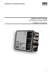
AST-200
AIS Transponder Antenna Splitter
Installation & User Manual
In accordance with a policy of continual development and product
improvement the AST-200 hardware and software may be
upgraded from time to time and future versions of the AST-200 may
therefore not correspond exactly with this manual.
When necessary, upgrades to the product will be accompanied by
updates or addenda to this manual. Information contained in this
manual is liable to change without notice.
Comar Systems Ltd. disclaims any liability for consequences
arising from omissions or inaccuracies in this manual and any other
documentation provided with this product.
© 2010 Comar Systems Ltd.
AST200 V1.0
2
1. Introduction
2. Installation
Congratulations on the purchase of your AIS Transponder Antenna Splitter.
It is recommended that your antenna splitter is installed by a professional
installer.
2.1 Before you start
The AST-200 allows your existing VHF antenna to be used by both a VHF
radiotelephone and an AIS Transponder.
The AST-200 also includes an antenna connection for FM broadcast
receivers providing a third use for your existing VHF antenna.
This manual describes the installation and operation of the AST-200.
3
The following items are supplied in the AST-200 packaging:
•
The AST 200 unit itself.
•
This operating manual.
You will need the following items and tools to complete the installation:
•
Class B AIS Transponder.
•
Pre-installed VHF Antenna and cable.
•
Access to 12V DC or 24V DC power supply where the unit is to be
installed, via a 1A rated fuse or circuit breaker.
•
Connector block or junction box for power connections.
•
Four M4 (no.6) screws or other fixings appropriate to the mounting
location.
4
Installation step 1
2.2 Installing the unit
Before starting installation select a suitable location for the antenna splitter.
The unit is intended for installation below deck in a dry location. When
locating the unit you should consider:
•
•
•
•
Routing of power and antenna cables to the unit.
Provision of sufficient space behind the unit for cable connections.
Maintaining the compass safe distance of 0.5m.
Visibility of the front panel indicators.
•
Secure the antenna splitter to a flat surface in the selected location.
Use four 5mm wood screws or other fixings suited to the material
the unit is being fixed to.
•
The unit may be installed in any orientation.
Installation step 2
Make the electrical connections to the antenna splitter as follows:
•
Remove the VHF antenna cable connection from your VHF Radio
and connect it to the connector labelled ‘Antenna’.
•
Connect the 1m cable marked “VHF Radio” to your VHF
Radiotelephone antenna connection.
•
Connect the 1m cable marked “AIS” to your AIS Transponder
antenna connection..
•
Optionally connect the antenna input of an FM Broadcast receiver
to the connector labelled ‘AM/FM’.
•
Connect 12VDC or 24VDC power supply to the power cable.
Installation diagram
o The red wire should be connected to the positive power
supply connection via a 1A rated fuse or circuit breaker.
o The black wire should be connected to the negative power
supply connection.
Installation step 3
Apply power and verify the unit is operating:
•
5
Apply power to the antenna splitter, AIS Transponder and VHF
radiotelephone.
6
•
Verify that the green power LED on the antenna splitter is
illuminated.
4. Troubleshooting
•
Transmit using the VHF radiotelephone and verify that the red LED
on the antenna splitter marked ‘VHF’ is illuminated during the
transmission.
Problem
•
Wait for the AIS Transponder to transmit its first position report.
This is indicated by the red LED TX on the AIS Transponder
illuminating. During AIS Transponder transmissions the red ‘AIS’
LED on the antenna splitter will flash briefly. Class B AIS
transmissions occur once every 3 minutes if your vessel is
stationary.
Solutions
•
Power LED not illuminated.
•
•
‘VHF’ LED does not illuminate when
VHF Radiotelephone is transmitting.
Check the antenna output of the
VHF radiotelephone is connected to
the antenna splitter input labelled
‘VHF’.
‘AIS’ LED does not illuminate when
AIS Transponder is transmitting.
Check the antenna output of the AIS
transponder is connected to the
antenna splitter input labelled ‘AIS’.
Clicks or pops are heard from a
connected FM broadcast receiver.
This is normal and may occur during
VHF or AIS transmission.
VHF or AIS reception range is
reduced.
A very slight reduction in receiver
range is normal and due to the
insertion loss of the antenna splitter.
3. Operation
Operation of the antenna splitter is automatic and requires no user
intervention.
•
During operation the antenna splitter will share signals received at
your VHF antenna with both the VHF Radiotelephone and the AIS
Transponder.
•
When either connected device transmits, the antenna splitter will
automatically route the transmission to the antenna.
•
VHF Radiotelephone transmissions (including DSC transmissions)
are given priority over AIS transmissions.
L
It is not possible for both connected devices to transmit
simultaneously using a single VHF antenna. Whilst you are
talking on your VHF Radiotelephone no AIS position reports
will be transmitted.
7
Check power supply
connections and fuse or
circuit breaker.
Check polarity of power
supply connections.
Check power supply
voltage.
8
5. Specification
6. Limited Warranty
General
Size (L x W x H)
Mounting area (L x W)
Weight
Power
Operating current (receive)
Operating current (VHF transmit)
Operating current (AIS transmit)
146 x 106 x 46mm
170 x 106mm
260g
12VDC or 24DC supply
65mA typical at 12VDC
135mA typical at 12VDC
135mA typical at 12VDC
Environmental
Operating temperature
Operating humidity
Storage temperature
-15°C to +55°C
Up to 93%
-20°C to +70°C
RF performance
VHF & AIS Frequency range
Insertion loss, AIS Receive path
Insertion loss, VHF Receive path
Insertion loss, AIS Transmit path
Insertion loss, VHF Transmit path
Max input power, AIS port
Max input power, VHF port
Min input power, VHF port
AIS port impedance
VHF port impedance
Antenna port impedance
FM port impedance
Switching time, Receive to AIS
Transmit
Switching time, Receive to VHF
Transmit
156.025MHz to 162.025MHz
Typical 4dB
Typical 4dB
Typical 0.8dB
Typical 0.8dB
12.5W
25W
5mW
50 Ω
50 Ω
50 Ω
75 Ω
Typical 20uS
Typical 20uS
Connectors
Power
Antenna
VHF Radiotelephone
AIS Transponder
FM broadcast receiver
1m 2 core cable
SO-239 (UHF) connector
PL259 on 1m lead
BNC Plug on 1m lead
RCA/Phono Socket
9
Comar Systems Ltd warrants this product to be free from defects in
materials and manufacture for one year from the date of purchase.
Comar Systems Ltd will, at its sole option, repair or replace any
components that fail in normal use. Such repairs or replacement will be
made at no charge to the customer for parts and labour. The customer
is, however, responsible for any transportation costs incurred in
returning the unit to Comar Systems Ltd.
This warranty does not cover failures due to abuse, misuse, accident or
unauthorized alteration or repairs.
The above does not affect the statutory rights of the consumer.
Note: Every effort has been made to ensure that all information
contained in this manual is accurate at the time of going to press.
However AIS is a new technology and the legislation is subject to
change. We therefore cannot take any responsibility for the content of
this manual and advise that you take normal steps to ensure that the
information is at its most current when you are reading this manual.
7. Product Support
Comar Systems Limited
Unit 7, Medina Court
Arctic Road
Cowes
Isle of Wight, PO31 7XD
United Kingdom
Telephone: +44 (0) 1983 282400 Fax: +44 (0)1983 280402
E-mail: [email protected]
Internet: www.comarsystems.com
10
11
12