1
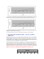
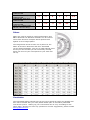
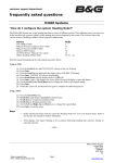
Brookes & Gatehouse Ltd.
Premier Way, Abbey Park
Romsey, Hampshire,
England
Tel: +44 (0)1794 518448
Fax: +44 (0)1794 518077
www.BandG.com
Swan 45 Performance Guide
January 2005
Prepared by:
Prepared for:
Nat Ives
Rosie Frost
INTRODUCTION
B&G has been involved with the Swan 45 Class from the very beginning when we
consulted on the specification of the electronics. Having now worked with the class
for a number of seasons we have refined our guide to the use of instruments
onboard such that you can truly maximise your performance and have accurate data
to help assess changes to sails, trim and set- up.
INSTRUMENT CALIBRATION
Accurate calibration of your chosen instrument system is essential for ensuring that
you are getting meaningful information from it that you can then use to measure the
performance of the yacht. The following sections describe how to do this on a typical
B&G system and where appropriate the headings detail the relevant B&G menu
structure. Where possible typical values for use on the Swan 45 have be given.
DEPTH (DEPTH → DEPTH, CALBRATE → DATUM)
For obvious safety reasons depth should be calibrated before any other function. A
DATUM (offset value) is set such that the depth display refers either to the waterline
or bottom of the keel. Enter a positive number for waterline or a negative number for
keel.
Typical value: –2.6m for depth below keel.
HEADING
Heading calibration is carried out using B&G’s Autoswing functionality that calibrates
the compass. An offset is then entered to account for the alignment of the compass
as installed on the yacht.
1. Autoswing (NAVIGATE → COMP CAL, CALBRATE → START)
Prior to commencing the swing ensure that no magnetic or large metallic objects are
placed near to the compass. Choose a calm open stretch of water and then begin the
calibration process as outlined in the User Manual ensuring you steer a steady circle
not exceeding 2- 3 degrees per second with a boat speed less than 5 knots.
2. Offset (NAVIGATE → HEADING, CALBRATE → CAL VAL 1)
Having completed the swing compare the compass heading with the bearing of a
known transit and correct it by entering an offset value.
BOATSPEED
All the work in the world on target speeds and angles, or on polar tables goes to
waste if boatspeed is inaccurate, even by a few %.
True wind calculations and performance functions depend on this input being
accurate. If boat speed is wrong, the whole system's data quality is compromised.
•
•
It is important to keep an eye on boatspeed accuracy during the course of a
season as paddlewheels do suffer from friction and hence changes in physical
characteristics can occur over time.
Regular cleaning of the paddlewheel is essential for accurate and repeatable
speed readings.
1. Auto- Calibration (SPEED → BOAT SPD, CALBRATE → AUTO CAL)
The B&G three run method eliminates any changes in current during the calibration
procedure since the runs are carried out in alternate directions. When carrying out
each run maintain a constant compass course to ensure that the distance covered is
the same as that measured on the chart. If possible choose a measured distance
with clearly visible transits marking each end.
Typical value: 3.52 Paddlewheel
It is prudent to manually calibrate boatspeed using the trip log function on anot her
FFD whilst running the auto cal feature. By recording the log at the beginning of each
run, and recording the log distance run for each leg, we can deduce the error in the
current speed calibration. This can be useful to complete a calibration procedure if
any of the runs have to be aborted due to a necessary change of course.
Example:
-
Current cal in Hz per Kt = 3.42
Measured run distance = 0.75nm
Run 1 = 0.76nm, Run 2 = 0.72nm, Run 3 = 0.77nm
It appears that the current is changing due to the difference in the first
and third runs Log distance. Correct this by averaging run 1 and 3,
and then combine with run two to get an overall average log distance:
(Run1 + Run3)/2 = 0.765
(Run2 + 0.765)/2 = 0.7425
Comparing the log distance to the actual distance reveals that the log
is under- reading by 1%
(0.75– 0.7425) = 1%
Increasing cal Hz/Kt in MANL CAL reduces boatspeed, and vice versa.
Therefore by reducing the cal Hz/Kt for the above calibration by 1%
will address the under- reading of the log.
3.42 - 1% = 3.39
If you are using the latest B&G Hercules system with a heel sensor you can also
adjust the speed from tack to tack and apply more correction at higher speeds in the
case of the paddle - wheel. See the Owner’s Manual for more information on this.
Once boatspeed has been verified as accurate, it should be monitored against other
functions, and only adjusted if the wrong speed cannot be attributed to different sail
trim, helmsman, rig settings, wind shear, crew weight and hull fouling.
APPARENT WIND CALIBRATION
If wind is not calibrated accurately, then performance is next to impossible to assess.
Proper calibration of the wind function is as vital as selecting the correct head sail for
the next upwind leg.
1. APPARENT WIND ANGLE (WIND→ APP W/A or MEAS W/A, CALBRATE →
MHU ANGL)
Installation offsets and other asymmetric factors can affect the symmetry of
measured wind angles. An offset is all that is required to correct for tack-to- tack
errors in APP W/A. The perfect scenario for calibrating APP W/A is in non- tidal flat
water, with stable conditions (no building sea breeze) and with a correctly calibrated
boatspeed.
Using identical trim and crew weight distribution (not necessarily a full racing crew)
complete half a dozen tacks with the helm concentrating purely on boatspeed. A
consistent speed (not necessarily from the targets table) on each tack should be
achieved without changing trim, and without using any reference to APP W/A. The
navigator or tactician should monitor the APP W/A from tack to tack, and average
each tack. Any difference between Port and Starboard tack can be corrected in the
MHU offset.
If Starboard APP W/A is greater than Port then subtract half the difference from the
MHU offset, and vice versa.
Once a good APP W/A is achieved, do not change it unless necessary (e.g. rig has
been removed from boat, new wind sensor put in place). Any differences seen from
now on may be attributable to effects such as wind shear and current.
2. APPARENT WIND SPEED
Do not alter the APP W/S calibration values. This is a wind tunnel based factory
setting.
TRUE WIND CALIBRATION TIPS
1. TRUE WIND ANGLE CALIBRATION (WIND → TRUE W/A, CALBRATE →
CORRECTION)
A TRUE W/A calibration matrix is utilised for corrections upwind, reaching, and
downwind across the TRUE W/S ranges.
Two methods of calibrating TRUE W/A are available, either monitoring TRUE DIR
from tack to tack or gybe to gybe, or using the compass to verify the angles the
yacht is tacking or gybing through.
1. If an error is seen in TRUE DIR, then the following rule applies
• If TWD is lifting you tack to tack then TRUE W/A is reading too wide, half the
error must be subtracted from the correction table.
• If TWD is heading you tack to tack then TRUE W/A is reading too narrow, add
half the error to the TRUE W/A table.
2. If according to the compass you are tacking through an angle different than the
sum of the TRUE W/A’s on each tack (Port TRUE W/A + Starboard TRUE W/A) then
the following rule applies
• If the tack angle < the sum of the TRUE W/A’s, the TRUE W/A is reading too
wide, half the error must be subtracted from the correction table.
• If the tack angle > the sum of the TRUE W/A’s, the TRUE W/A is reading too
narrow, add half the error to the TRUE W/A table.
A Worked Example:
Your TRUE DIR is telling you that you are being lifted by 10 degrees from tack to
tack (or the sum of your TRUE W/A is 10 degrees more than the angle you are
tacking through), and you know this is wrong. This is in 5 kts of TWS. When you go
into the TRUE W/A correction table for 5 Kt upwind, you see that a value of –1.5
degrees is already entered. To correct the error you are seeing, a further 5 degrees
needs to be subtracted so a total correction of –6.5 degrees is applied.
Calibrating and refining TRUE W/A is an ongoing process. Differences in TRUE W/A
can been seen from morning to afternoon races as sea breezes develop and changes
in gradient conditions. TRUE W/A should be checked at the beginning of every race,
any necessary changes made, and the conditions logged for future reference.
Typically, when graphed, a TRUE W/A table for upwind might have a curve like the
following:
If it has only been possible to achieve reliable values for the TRUE W/S 5, 10 and 20
range and the rest of the table left blank then the table would look as follows:
It is clear to see that the 15, 25, and 30 kt values can be accurately guessed at as
opposed to being left with zero values.
You should repeat the process for reaching and running as well as beating.
2. TRUE WIND SPEED CALIBRATION (WIND → TRUE W/S, CALBRATE →
CORRECTION)
TRUE W/S errors are seen from sailing upwind to downwind. This is most noticeable
on Mast Head boats, however all yachts are affected to some degree. This is due to
the acceleration of the airflow over the top of the mast and around the sails when
sailing downwind. The introduction of the Vertical Mast Head unit has gone some way
to solving this, however calibration may still be necessary.
As a rule of thumb, it is safe to put a correction of –10% into the table before first
sailing and this is the value entered by B&G as a factory default. Monitoring the
change in TRUE W/S from close hauled to flat running will enable further refinement
of this calibration value. On a B&G Hercules system it is also possible to define the
TRUE W/A at which this correction is applied – typically your downwind target angle.
Typical corrections for TRUE W/A and TRUE W/S for the Swan 45:
TRUE W/S
5
10
15
20
25
30
UPWIND TRUE W/A
CORRECTION
REACHING TRUE W/A
CORRECTION
DOWNWIND TRUE W/A
CORRECTION
DOWNWIND TRUE W/S
CORRECTION
TRUE W/S CORRECTION
ANGLE (Hercules Only)
-7
-3
-2.5
4.5
6.5
8.0
-2
-1
0
1
1
1.5
4
3
1
-1
-1
-2
-1
-1.5
-2
-2.2
-2.5
-3
143
150
172
174
172
168
Polars
Polars are used to profile a yacht’s performance and
B&G’s Deckman for Windows software can be used to
store these and then compare actual performance
against a set of target polars.
The image below shows a basic set of polars for the
Swan 45 stored in Deckman and their associated
curves plotted alongside. They are a good starting point
but as you sail the boat you will most likely develop
these into a set of your own specific to your sails and
set- up.
Conclusion
The information above should help you get up to speed as quickly as possible and
then move forward with your own polars based upon an accurately calibrated
instrument system. Setting up your instruments can be very rewarding for the
whole team. Should you have any questions or further suggestions, please contact
[email protected]
Author
Nat Ives is the B&G Race Specialist and also looks after the Custom Projects team.
He is a qualified Naval Architect and an experienced navigator having competed in a
wide range of yachts and events including the Cascais Race, Fastnet Race, Prada
Challenge for Classic Yachts, RORC Offshore Series, Cowes, Cork and the Port Huron
to Mackinaw Race. Last season he was the full- time navigator on Swan 45 FEVER.