1
TS-5500 User’s Manual
Technologic Systems
3 Power
The TS-5500 requires regulated 5VDC at 900 mA (typical). A quick release screw-down terminal block
for the 5V power and power GND connections is provided for easy connection to an external power
supply.
When power is first supplied to the TS-5500, the board mounted LED is immediately turned on under
hardware control. Once the processor begins execution, the LED is turned off. The LED then turns on
then off to provide a characteristic blink during execution of POST. If the LED does not turn on at all, the
most likely problem is the power supply. Check that the +5V and GND connections are not reversed. A
diode protects the board against damage in such a situation, but it will not run.
Please note that supply voltages over 6 VDC may damage the TS-5500.
Be sure to use a regulated 5 VDC power supply.
4 Memory
4.1
SDRAM
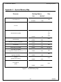
The TS-5500 has a total of 32 Megabytes (MB) of high-speed SDRAM providing 640 Kilobytes (KB) of
base memory, 15 MB of extended memory, and 128 KB of shadow RAM for the BIOS. This is identical
to a standard PC memory map. The TS-5500 can be ordered with 16MB or 64MB of SDRAM, but it is
not field upgradeable.
The TS-5500 SDRAM chips are soldered directly to the board. By not using a SIMM socket, the TS5500 is much more reliable in high-vibration environments.
4.2
Flash
There is a total of 2 MB of Flash memory on the TS-5500 with 128 KB reserved for the BIOS. During
POST, this 128 KB area is copied from Flash into SDRAM at addresses E0000h through FFFFFh for
improved performance (a standard technique known as BIOS Shadowing). The remainder of the Flash
memory (1920 KB) is configured as two solid-state disk (SSD) drives appearing as drive A and drive B.
Drive A uses 896 KB of Flash memory while drive B uses the remaining 1024 KB of Flash memory.
Both drives are fully supported by the BIOS as INT 13h drives.
The physical Flash memory is accessed by the BIOS in protected mode at memory address 148M.
The Flash memory is guaranteed capable of a minimum of 100,000 write/erase cycles. This means that
if you completely erase and rewrite the SSD drive 10 times a day you have over 27 years before any
problems would occur. Reading the SSD produces no wear at all.
Power failure during flash writes can cause corruption of flash drive FAT tables (A: or B:). Therefore
applications writing frequently should use DiskOnChip or Compact Flash card drives which are more
tolerant of power failure during write cycles.
Flash drive A is read-only when JP3 is not installed. Removing JP3 also makes the 128 kbyte BIOS
area of the Flash write protected as well. Write protecting the A: drive can be useful if there are critical
files in the final product that must be very secure.
4.3
Compact Flash cards and DiskOnChip modules
If 2MB of Flash is insufficient for your application, additional non-volatile storage can be added with a
Compact Flash card or an M-Systems DiskOnChip module. Either of these products can supply
additional storage that will behave much as a hard drive does in a typical PC with sizes ranging from
8MB to 512MB. These products are inherently more rugged than a hard drive since they are completely
solid-state with no moving parts.
The Compact Flash card has the added advantage of being removable media. A SanDisk USB
Compact Flash reader/writer (which is included in the TS-5500 Developer’s Kit) is recommended for the
6
05/22/09