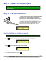
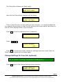
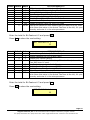
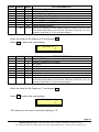
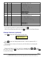
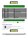
1
MH-3000 QUICK SHIP
SETUP MANUAL
Start
H er e
Virginia Controls, Inc. ● 2513 Mechanicsville Turnpike ● Richmond, Virginia 23223
Tel: (804) 225-5530 ● Fax: (804) 225-0116 ● email: [email protected] ● web site: www.vacontrols.com
Step 1.
Your Quick Ship Controller
Your MH-3000-QS Control System was specifically
designed to be a completely customizable and off-the-shelf
hydraulic elevator control solution.
It includes the following popular features, voltage options
and motor starting abilities:
•
Maximum 6 landings (front
openings only)
•
Position Indicator Circuit (line
per floor; with blanking option)
•
Simplex Selective Collective
Operation
•
Direction Arrow Circuit
•
Car Travel Lantern (selectable 1
stroke, 2 stroke gong program)
•
Firemen’s Service Phase I & II
(1998, 2000 or 2004 ANSI
A17.1, 1998 or 2001 Chicago,
New York City or Canadian B44.1
Fire Codes)
•
Shunt Trip Delay Interface
Operation
•
Interface for GAL MOD or MOVFR
passenger door operators
•
Door Contact Fault Monitoring
•
Differential Car/Hall Door Time
•
Independent Service
•
Inspection Access; Top & Bottom
•
Top of Car Inspection Operation
•
Slow Speed Running on
Inspection
•
Low Oil Switch Operation
•
Oil Viscosity (Churn) Operation
•
Car-to-Lobby Switch at Main
Landing
•
EECO, Maxton or Equivalent
Valve Interface
•
Flood Switch Operation
•
Reverse Phase Relay
•
Door Nudging for Infrared
Curtain Unit
•
36”H x 36”W x 7”D NEMA 1 Wall
Mountable Enclosure
•
115VAC Signal/Control/Valve
Voltages
•
•
Illuminated Car & Hall Button
Circuits
Wye-Delta Starting: Up to 30HP
@ 208V; 40HP @ 230V; 50HP @
480V
•
UL / cUL Label
•
Passing Gong Circuit
•
TSSA Approved
•
Barrier Free Gong Circuit
•
208/230/240/460/480V-3Ph60Hz Building Supply
Page 2
Virginia Controls, Inc. ● 2513 Mechanicsville Turnpike ● Richmond, Virginia 23223
Tel: (804) 225-5530 ● Fax: (804) 225-0116 ● email: [email protected] ● web site: www.vacontrols.com
Step 2.
Stop and Review the Following:
It is strongly recommend that you read this setup manual carefully
before proceeding with the installation.
Important information is highlighted by the headings WARNING,
CAUTION, or NOTE and is defined as follows:
WARNING - Warnings are used to indicate instructions which, if not followed
correctly, will probably result in personal injury or substantial damage to
equipment.
CAUTION - Cautions are used to indicate instructions or information which, if
not observed, may result in some damage to equipment if care is not taken.
NOTE - Notes are used to indicate instructions or information which is
especially helpful in understanding and operating the equipment, and which
will usually speed up the installation process.
The following general rules and safety precautions must be
observed for the safe and reliable operation of your system.
WARNING: The elevator controller must be installed by
experienced field installation personnel. The installer must
know and follow all the rules and regulations pertaining to the
safe installation and running of elevators. Additional information for specific
devices (such as the valves, door operator, etc.) is the responsibility of the
manufacturers of those devices.
WARNING: This equipment is designed and built to comply with ANSI A17.1
and national electrical code and must be installed by a qualified contractor.
The contractor is responsible for ensuring that the final installation complies
with all applicable local, state and national codes, and is installed safely.
WARNING: The 3 phase AC power supply to this equipment must come from
a fused disconnect switch or circuit breaker which is sized in accordance with
all applicable national, state and local electrical codes, in order to provide the
necessary overload protection for the controller and motor. Incorrect motor
branch circuit protection may create a hazardous condition.
WARNING: Proper grounding is vital for the safe operation of your system.
Bring the ground wire to the ground stud that is labeled "GND" or "G". You
must choose the proper conductor size. See national electrical code article
250-95, or the related local applicable code.
Page 3
Virginia Controls, Inc. ● 2513 Mechanicsville Turnpike ● Richmond, Virginia 23223
Tel: (804) 225-5530 ● Fax: (804) 225-0116 ● email: [email protected] ● web site: www.vacontrols.com
Step 3.
Follow these Guidelines
Controller Mounting
Mount the controller in a location that provides:
•
adequate support for the weight of the
controller,
•
adequate lighting for installation and
maintenance,
•
convenient access for the routing of required
conduits and cables,
•
convenient access to other devices in the machine room,
•
a minimum of vibration (supply additional bracing or reinforcement if
required).
Controller Environment
For improved controller reliability:
•
Keep the machine room clean.
•
Do not install the controller in a dusty area.
•
Do not install the controller in a carpeted area, or area where static
electricity is a problem.
•
Keep room temperature between 0°C to 50°C (32°F to 122°F), and 95%
non-condensing relative humidity. Extended high temperatures will shorten
the life of electronic components. Provide adequate ventilation or airconditioning as required.
•
Avoid condensation on the equipment by keeping the controller away from
sources of condensation and water (such as open windows) as these can
create a hazardous condition and can damage the equipment.
•
Do not install the controller in a hazardous location and where excessive
amounts of vapors or chemical fumes may be present.
•
Make sure power line fluctuations are within ±10%.
•
High levels of radio frequency emissions may cause interference with the
controller microprocessor, and produce unexpected and even dangerous
results. This could be caused by hand-held communications devices used
near the controller.
Page 4
Virginia Controls, Inc. ● 2513 Mechanicsville Turnpike ● Richmond, Virginia 23223
Tel: (804) 225-5530 ● Fax: (804) 225-0116 ● email: [email protected] ● web site: www.vacontrols.com
Step 4.
Wire up your controller
Controller Grounding
Grounding of the controller must conform to all applicable
codes. Proper grounding is essential to the safe operation of the
equipment. It will also reduce the likelihood of noise-induced
problems, which could include CPU crashes, or I/O
communication errors.
•
The grounding wire should be sized per the applicable codes.
•
Connect the ground to a good building ground, such as the structural steel
of the building, or a cold water pipe.
Car and Hoistway Wiring
Be sure to carefully review the schematics and field wiring diagrams before
attempting to hook up your controller.
Step 5.
•
Check the basics before applying power
•
Verify that the primary wiring of transformer CCXF
matches your building supply voltage.
•
Verify that the primary wiring of transformer DOXF
matches your building supply voltage.
•
Verify that the secondary wiring of transformer
DOXF matches your door operator voltage
requirement (see schematic sheet D).
Verify that the phase monitor voltage matches your building supply
voltage.
Page 5
Virginia Controls, Inc. ● 2513 Mechanicsville Turnpike ● Richmond, Virginia 23223
Tel: (804) 225-5530 ● Fax: (804) 225-0116 ● email: [email protected] ● web site: www.vacontrols.com
Step 6.
Apply power
•
Remove all fuses from the controller. See table below
for their description and sizes.
•
Turn ON the Mainline Disconnect and measure the
building supply voltage at F1A, F2A & F3A terminals.
•
Turn OFF the Mainline Disconnect.
•
Install fuses F1, F2 & F3.
•
Turn ON the Mainline Disconnect
•
Verify that the building supply voltage is present at F1B, F2B & F3B
terminals.
•
Verify that 115VAC is present across terminals F4A & 35.
•
Turn OFF the Mainline Disconnect.
•
Install fuses F4, F5 & F6.
•
Turn ON the Mainline Disconnect and verify the following:
o 115VAC is present across terminals 1 & 35
o [With MOD Door] 115VAC is present across terminals AC1 & AC2
o [With MOVFR Door] 230VAC is present across terminals AC1 & AC2
•
Turn OFF the Mainline Disconnect.
•
Install fuse F9.
•
Turn ON the Mainline Disconnect.
Fuse
Description
Size
F1, F2
Controller Mainline
6 Amp 600 Volt
F3
Controller Mainline
1 Amp 600 Volt
F4
AC supply
3 Amp 250 Volt
F5, F6 Door Operator supply 3 Amp 250 Volt
F9
Hall Common
1 Amp 250 Volt
Fuse Description and Size
Page 6
Virginia Controls, Inc. ● 2513 Mechanicsville Turnpike ● Richmond, Virginia 23223
Tel: (804) 225-5530 ● Fax: (804) 225-0116 ● email: [email protected] ● web site: www.vacontrols.com
Step 7.
Prepare for Temporary Run
NOTE: You can run the elevator on temporary run buttons without using the
microprocessor, as described in the MH-3000 User Manual under “Temporary
Run Connections”.
Step 8.
Setup Your Software
Unlike other Virginia Controls hydraulic elevator
controllers you have purchased, this system
requires you to initially configure the program to
setup the features and functions you require.
When the microprocessor is powered up, the
LCD display will show the Status Screen. The
screen will be similar to that shown below:
INS
1 DC
NoHC
PwrOK
CLSD
Reset Default Factory Settings (required)
Note: This section should be done in all installations
Press Nxt twice to show the menu selection for the Car Setup Menu.
Press ENTER to
GO TO SETUP MENU
Press Ent, and the Warning screen will be shown.
WARNING: PROGRAM
& CAR WILL STOP!
If it is safe to stop the car, press Ent.
Page 7
Virginia Controls, Inc. ● 2513 Mechanicsville Turnpike ● Richmond, Virginia 23223
Tel: (804) 225-5530 ● Fax: (804) 225-0116 ● email: [email protected] ● web site: www.vacontrols.com
The Setup Menu Banner will flash briefly,
VirginiaControls
MAIN SETUP MENU.
then the first Setup Menu selection will be shown.
Press ENTER to
RESET SETTINGS
If this is the first time you are setting up the controller, it is recommended that
you reset all the settings, so that you are starting with known values, as shown on
the MH-3000 Settings sheet in the schematic.
Press Ent. You will be asked to enter a password.
ENTER PASSWORD
Press
9
1
1 .
ENTER PASSWORD
911
Press Ent. A screen will briefly indicate all settings have been reset, then the
Reset Settings screen will be shown again.
Change Settings for Your Job (optional)
Note: This section should be performed if the default settings do not match
your job (number of landings, designated Fire Landings, etc.)
Press Nxt to go to the Change Settings menu selection.
Press ENTER to
CHANGE SETTINGS
Page 8
Virginia Controls, Inc. ● 2513 Mechanicsville Turnpike ● Richmond, Virginia 23223
Tel: (804) 225-5530 ● Fax: (804) 225-0116 ● email: [email protected] ● web site: www.vacontrols.com
Press Ent to enter the Change Settings submenu.
If you entered the password above, it is not necessary to enter it again. If you
have not entered the password then you will see the screen shown above telling
you to enter the password. In this case press 9 1 1 then Ent.
The first setting will be shown.
NUM.OF IO BOARDS
4
This value is the number of Input/Output boards, and does not need to be
changed.
Press Nxt to show the next setting.
NUMBER OF LDGS.
2
If there are more than two landings, enter the number of landings then press
Ent.
Press Nxt to show the next setting.
MAIN FIRE LDG..
1
If the bottom landing is not the Main Fire Landing, press the number for the Main
Fire Landing, then press Ent.
NOTE: For all settings that involve selecting a landing, “1” corresponds to
the bottom landing, “2” is the next landing, and so on. Do not use the
building names.
Press Nxt to show the next setting.
ALT. FIRE LDG..
2
If the second landing is not the Alternate Fire Landing, press the number for the
Alternate Fire Landing, and then press Ent.
Press Nxt to show the next setting.
Page 9
Virginia Controls, Inc. ● 2513 Mechanicsville Turnpike ● Richmond, Virginia 23223
Tel: (804) 225-5530 ● Fax: (804) 225-0116 ● email: [email protected] ● web site: www.vacontrols.com
HOME LANDING...
1
If Homing is to be enabled, and the Home Landing is not the bottom landing,
press the number for the Home Landing, and then press Ent.
Press Nxt to show the next setting.
FRONT DOOR CODE
255
The Front Door Code selects which landings have front doors. A value of 255
enables the front doors at all floors. This value should not normally be changed.
Press Nxt to show the next setting.
REAR DOOR CODE.
0
The Rear Door Code selects which landings have rear doors. A value of 0 disables
rear doors. This value should not normally be changed.
Change Settings – Bit Features (optional)
Press Nxt to show the next setting.
BIT FEATURES # 1
2
The Bit Features are binary coded values that combine a group of eight individual
features into one setting. The breakdown for the value of each Bit Feature setting
is shown here, and in the schematic on the Settings sheet. A description of the
features is shown here and in the User Manual.
For each Bit Feature, read the description of the feature in the right column of
the table below and determine whether the feature should be enabled. If it should
be enabled, write the number found in the Value column in the Actual column (see
table below). Repeat this for all eight features. Now add up the values in the
Actual column and enter this value in the Actual Total box, and enter it as the new
value of the Bit Feature. The default column shows the factory default setting.
The Bit Features are preset to the most common values.
Page 10
Virginia Controls, Inc. ● 2513 Mechanicsville Turnpike ● Richmond, Virginia 23223
Tel: (804) 225-5530 ● Fax: (804) 225-0116 ● email: [email protected] ● web site: www.vacontrols.com
Note: If you do not require 2000 Code, then change Bit Features #1 to “0”;
Bit Feature # 3 to “5”; Bit Feature # 4 to “0”.
Actual Default
2
2
Value
1
BIT FEATURES # 1
Disable Fire Service - Turn this feature on to disable Fire
Service. This feature should be turned on if Fire Service is not
provided. It may also be turned on during initial installation, if
the Smoke Sensors or Fire Switches have not yet been installed.
2
Enable 2000 ANSI Fire Code - Turn this feature on to enable
2000 or 2004 National Fire Code. The default code is 1998 Fire
Code.
4
Enable New York Fire Code - Turn this feature on to enable New
York Fire Code.
8
Enable 2001 Chicago Fire Code - Turn this feature on to enable
2001 Chicago Fire Code. The Fire Switches and Sensors must be
connected as required by the appropriate Fire Code. Refer to the
appropriate wiring diagrams in the schematic.
16
Enable 1998 Chicago Fire Code - Turn this feature on to enable
1998 Chicago Fire Code. The Fire Switches and Sensors must
be connected as required by the appropriate Fire Code. Refer to
the appropriate wiring diagrams in the schematic.
32
Use 2 Inputs for 1998 Chicago Fire Code - Turn this feature on
to use 2 inputs for the Fire Inputs for Chicago 1998 Fire Code.
The Fire Switches and Sensors must be connected as required
by the appropriate Fire Code. Refer to the appropriate wiring
diagrams in the schematic.
64
Enable Canadian Fire Code - Turn this feature on to enable 1998
Canadian B44 Fire Code. The Fire Switches and Sensors must be
connected as required by the appropriate Fire Code. Refer to the
appropriate wiring diagrams in the schematic.
128
Enable Bldg Fire Sw for 2000 Fire Code - Turn this feature on to
enable the Remote Fire Sw on 2000 Fire Code.
TOTAL Add up the values for each feature that you want to be on, then
write down that value in the Actual Total box at the left, for your
records, and enter it in the microprocessor.
Enter the total for Bit Feature # 1 and press Ent.
Press Nxt to show the next setting.
BIT FEATURES # 2
0
Page 11
Virginia Controls, Inc. ● 2513 Mechanicsville Turnpike ● Richmond, Virginia 23223
Tel: (804) 225-5530 ● Fax: (804) 225-0116 ● email: [email protected] ● web site: www.vacontrols.com
Actual Default
0
Value
1
2
4
8
16
32
64
128
TOTAL
BIT FEATURES # 2
Kill Independent immediately on Fire Service
No Timed Kill of Independent on Fire Service
Never kill Independent on Fire Service
Main Fire Landing at Rear Opening
Alternate Fire Landing at Rear Opening
Disable Shunt Trip on Fire Service Phase 2
Enable Shunt Trip on Inspection
Disable ECReturn Latch on 2000 Fire Code
Add up the values for each feature that you want to be on, then
write down that value in the Actual Total box at the left, for your
records, and enter it in the microprocessor.
Enter the total for Bit Feature # 2 and press Ent.
Press Nxt to show the next setting.
BIT FEATURES # 3
13
Actual Default
1
4
8
13
Value
1
2
4
8
BIT FEATURES # 3
Enable Pulsing Selector (off=Floor Sws)
Enable Separate Call I/O (4 Wire Calls)
Enable Door Check Feature
Enable Redundancy Fault Checking. This should only be enabled
if an MH5 board is used.
16
Use Car Lantern outputs for Hall Lanterns
32
Do Not Run On Fire Service and BORIS
64
Do Not Run on Fire Service and Shutdown
128
Allow Stop at Upper Floor on Shutdown
TOTAL Add up the values for each feature that you want to be on, then
write down that value in the Actual Total box at the left, for your
records, and enter it in the microprocessor.
Enter the total for Bit Feature # 3 and press Ent.
Press Nxt to show the next setting.
BIT FEATURES # 4
16
Page 12
Virginia Controls, Inc. ● 2513 Mechanicsville Turnpike ● Richmond, Virginia 23223
Tel: (804) 225-5530 ● Fax: (804) 225-0116 ● email: [email protected] ● web site: www.vacontrols.com
Actual Default
16
16
Value
1
2
4
8
16
32
64
128
TOTAL
BIT FEATURES # 4
Enable CKO on Independent
Fire Sensors are Normally Open Inputs
Dir Indicators show actual direction on Attend.
Med Emerg Buzzer on Independent only
Enable Full Redundancy Fault Checking
Always Enable DOB at Front Openings
Always Enable DOB at Rear Openings
Disable Non-Shutdown Faults in Fault Log
Add up the values for each feature that you want to be on, then
write down that value in the Actual Total box at the left, for your
records, and enter it in the microprocessor.
Enter the total for Bit Feature # 4 and press Ent.
Press Nxt to show the next setting.
BIT FEATURES # 5
40
Actual Default
8
32
40
Value
1
2
4
8
16
32
64
128
TOTAL
BIT FEATURES # 5
Flood Return Ldg is 3 (not 2)
Flood Return Ldg is Top Ldg (not 2)
Flood overrides Independent, Attendant, Med Emerg
Flood overrides Shutdown (Low Oil, Rev. Phase, etc)
Do Not Run on Flood and BORIS
Do Not Run Down Below Main on Flood and Shutdown
Fire Service Overrides Flood Operation
Flood Operation Overrides Hall Fire Service
Add up the values for each feature that you want to be on, then
write down that value in the Actual Total box at the left, for your
records, and enter it in the microprocessor.
Enter the total for Bit Feature # 5 and press Ent.
Press Nxt to show the next setting.
BIT FEATURES # 6
64
Page 13
Virginia Controls, Inc. ● 2513 Mechanicsville Turnpike ● Richmond, Virginia 23223
Tel: (804) 225-5530 ● Fax: (804) 225-0116 ● email: [email protected] ● web site: www.vacontrols.com
Actual Default
64
64
Value
1
2
4
8
16
32
64
128
TOTAL
BIT FEATURES # 6
Enable Shunt Trip Feature
Enable Low Oil Switch Feature
Enable Oil Viscosity Feature
Enable Rear Door Open Output
Enable RD (RearDoor) Output
Enable Car To Lobby Input
Disable DISC Input (BORIS is not used)
Enable Nudging Output
Add up the values for each feature that you want to be on, then
write down that value in the Actual Total box at the left, for your
records, and enter it in the microprocessor.
Enter the total for Bit Feature # 6 and press Ent.
Press Nxt to show the next setting.
BIT FEATURES # 7
0
Actual Default
0
Value
1
2
4
8
16
32
64
128
TOTAL
BIT FEATURES # 7
Enable CKO Output
Enable PI Blanking Fire Output
Not Used
Not Used
Not Used
Not Used
Not Used
Not Used
Add up the values for each feature that you want to be on, then
write down that value in the Actual Total box at the left, for your
records, and enter it in the microprocessor.
Enter the total for Bit Feature # 7 and press Ent.
Press Nxt to show the next setting.
BIT FEATURES # 8
0
This feature is not used. Leave the setting as “0”
Page 14
Virginia Controls, Inc. ● 2513 Mechanicsville Turnpike ● Richmond, Virginia 23223
Tel: (804) 225-5530 ● Fax: (804) 225-0116 ● email: [email protected] ● web site: www.vacontrols.com
Press Nxt to show the next setting.
BIT FEATURES # 9
0
This feature is not used. Leave the setting as “0”
Press Nxt to show the next setting.
BIT FEATURES #10
0
This feature is not used. Leave the setting as “0”
Proceed through each of the settings, making any changes required. Refer to the
User Manual for a description of the settings. Most settings can be left at the
factory default. Use the chart below to record any changes.
Page 15
Virginia Controls, Inc. ● 2513 Mechanicsville Turnpike ● Richmond, Virginia 23223
Tel: (804) 225-5530 ● Fax: (804) 225-0116 ● email: [email protected] ● web site: www.vacontrols.com
Summary of Settings
Review this table. It provides a summary of all the settings entered previously,
and the rest of the adjustable settings available (such as Door Times).
If any values are to be changed, write the new value in the “Actual” column on
the left.
NOTE: Keep this sheet and the next sheet as a record of the settings for this
job. If a Factory Reset is performed, the controller will need to be reset back
to these settings.
Actual Default
4
2
1
2
1
255
0
2
0
13
16
40
64
0
0
0
0
0
0
0
0
0
Screen Display
NUM.OF IO BOARDS
NUMBER OF LDGS.
MAIN FIRE LDG..
ALT. FIRE LDG..
HOME LANDING...
FRONT DOOR CODE
REAR DOOR CODE.
BIT FEATURES # 1
BIT FEATURES # 2
BIT FEATURES # 3
BIT FEATURES # 4
BIT FEATURES # 5
BIT FEATURES # 6
BIT FEATURES # 7
BIT FEATURES # 8
BIT FEATURES # 9
BIT FEATURES #10
CUSTOM TIME #0.1
CUSTOM TIME #0.2
CUSTOM TIME #0.3
CUSTOM TIME #0.4
CUSTOM TIME #0.5
50
30
10
20
0
0
0
DOOR TIME, HALL
DOOR TIME, CAR.
DOOR TIME, SHORT
LEVELING LOCKOUT
CUSTOM TIME #1.1
CUSTOM TIME #1.2
CUSTOM TIME #1.3
25
25
SHUTDOWN TIME..
NUDGING TIME...
Description
Number Of IO Boards
Number Of Landings
Main Fire Landing
Alternate Fire Landing
Home Landing
Front Door Code (See Above)
Rear Door Code (See Above)
Bit Features # 1 (See Above)
Bit Features # 2 (See Above)
Bit Features # 3 (See Above)
Bit Features # 4 (See Above)
Bit Features # 5 (See Above)
Bit Features # 6 (See Above)
Bit Features # 7 (See Above)
Bit Features # 8 (See Above)
Bit Features # 9 (See Above)
Bit Features # 10 (See Above)
Custom Time # 0.1 – Not Used
Custom Time # 0.2 – Not Used
Custom Time # 0.3 – Not Used
Custom Time # 0.4 – Not Used
Custom Time # 0.5 – Not Used
0.1 SEC TIMERS
Door Time, Hall Calls
Door Time, Car Calls
Door Time, Shortened
Leveling Lockout
Custom Time #1.1 – Not Used
Custom Time #1.2 – Not Used
Custom Time #1.3 – Not Used
1.0 SEC TIMERS
Shutdown Time (Adjust if desired)
Nudging Delay
Page 16
Virginia Controls, Inc. ● 2513 Mechanicsville Turnpike ● Richmond, Virginia 23223
Tel: (804) 225-5530 ● Fax: (804) 225-0116 ● email: [email protected] ● web site: www.vacontrols.com
20
10
15
20
10
30
30
30
0
0
EYE CUTOUT TIME
HOMING DELAY...
CAR STUCK TIME.
DOOR STUCK TIME
DOOR RESET TIME
KILL IDS ON FIRE
DR CLOSE ON FIRE
CUSTOM TIME #2.1
CUSTOM TIME #2.2
CUSTOM TIME #2.3
30
PI CUT OUT TIME
30
30
0
CUSTOM TIME #3.1
CUSTOM TIME #3.2
CUSTOM TIME #3.3
45
1
0
0
0
SPECIAL
SPECIAL
SPECIAL
SPECIAL
SPECIAL
VALUE
VALUE
VALUE
VALUE
VALUE
#1
#2
#3
#4
#5
Electric Eye Cutout Time
Homing Delay
Car Stuck Time
Door Stuck Time
Door Stuck Reset Time
Kill Independent On Fire Service
Door Close on Fire Service
Custom Time #2.1
Custom Time #2.2
Custom Time #2.3
10 SEC TIMERS
P.I. Cut Out Time (Set to “0” if the Position
Indicators should stay on)
Custom Time #3.1
Custom Time #3.2
Custom Time #3.3
Password Protected Settings
Special Value 1
Special Value 2
Special Value 3
Special Value 4
Special Value 5
If you want to go back to a previous setting, press Prv.
After all the settings have been set, press Esc to return to the Setup Submenu.
Change Features (optional)
Press Nxt to show the Change Features menu item.
Press ENTER to
CHANGE FEATURES
Press Ent to enter the Change Features menu. Enter the password 911, if
requested.
The first feature is shown on the top line, with the bottom line showing the
current setting.
Review each feature, and if any need to be changed, press Nxt or Prv to get to
the feature, then press Aux to toggle between DISABLED and ENABLED. Press Ent
to accept the change.
Page 17
Virginia Controls, Inc. ● 2513 Mechanicsville Turnpike ● Richmond, Virginia 23223
Tel: (804) 225-5530 ● Fax: (804) 225-0116 ● email: [email protected] ● web site: www.vacontrols.com
NO SHORTDOORTIME
DISABLED
NOTE: Keep this sheet as a record of the features for this job. If a Factory
Reset is performed, the controller will need to be reset back to these
features.
Actual
Default
Disabled
Disabled
Disabled
Disabled
Disabled
Enabled
Disabled
Disabled
Screen Display
NO SHORTDOORTIME
TIMED EYE CUTOUT
DOOR NUDGING...
1 STROKE DN LANT
SLOW ON INSPECT
PROXIMITY DETECT
SHORT FLOORS...
ENABLE HOMING..
Disabled
Disabled
Disabled
Disabled
Disabled
SPECIAL
SPECIAL
SPECIAL
SPECIAL
SPECIAL
FEATURE1
FEATURE2
FEATURE3
FEATURE4
FEATURE5
Description
Disable Shortened Door Time
Enable Timed E.Eye Cutout
Enable Door Nudging
Enable 1 Stroke Down Lanterns
Slow Speed On Inspection
Enable Proximity Detector
Enable Short Floor Circuitry
Enable Homing
Password Protected Settings
Special Feature 1
Special Feature 2
Special Feature 3
Special Feature 4
Special Feature 5
NOTE: See the MH-3000 User Manual for a complete description of each
feature.
When all features have been set, as desired, press Esc to return to the Setup
Submenu.
Set the TIME (required)
Press Nxt three times to go to the “Change the Time” submenu.
Press Ent to Change the Time.
The current time is displayed, showing the time in 24hour format, and the
month, date, and year.
CURRENT TIME
12:22 04/13/05
Page 18
Virginia Controls, Inc. ● 2513 Mechanicsville Turnpike ● Richmond, Virginia 23223
Tel: (804) 225-5530 ● Fax: (804) 225-0116 ● email: [email protected] ● web site: www.vacontrols.com
If these are correct, then press Esc to return to the Setup Menu.
If you want to change the time and/or date, then press any other key to continue
with the next menu item.
You will be prompted to enter the year (00-99), month (1-12), date (1-31), hour
(0-23), and minute (0-59).
ENTER YEAR 00-99
05
In each case, press Ent to accept the current value, or enter the correct value
then press Ent.
If an incorrect value is entered, just enter the correct value again, and press Ent.
If you press Esc during this sequence, then the time and date will not be updated,
and the display will return to the setup menu.
After all the data has been entered, the screen will display the new time and
date, with the prompt “Enter to accept”.
ENTER TO ACCEPT
12:23
04/13/05
Press Ent to accept the values. At this point the new time and date will be
accepted, and the seconds value will be set to zero. If you press Esc, then you will
return to the setup menu without entering the new time and date.
Return to the Run Mode
The software setup is now complete. Press Esc to return to the Run Mode.
The display will show the Car Status screen.
Page 19
Virginia Controls, Inc. ● 2513 Mechanicsville Turnpike ● Richmond, Virginia 23223
Tel: (804) 225-5530 ● Fax: (804) 225-0116 ● email: [email protected] ● web site: www.vacontrols.com