1
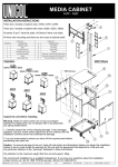
BioFrac Franction Collector
F1
A
F2
F3
F4
F5
1
2
3
4
5
6
7
8
9
0
B
VALVE A
VALVE B
B IO L OGIC D UO F LOW™
CHROMATOGRAPHY SYSTEM
INSTRUCTION MANUAL
(BioLogic DuoFlow™ Software Version 5.0)
Copyright © (2003) Bio-Rad Laboratories, Inc. All rights reserved.
TABLE OF CONTENTS
TABLE OF CONTENTS
SAFETY
SECTION 1.
Chapter 1.0
1.1
1.2
1.3
1.4
1.5
SYSTEM OVERVIEW
Introduction ...............................................................................................................1-1
Overview .....................................................................................................................1-1
Features ......................................................................................................................1-2
Unpacking ...................................................................................................................1-3
System Configurations ................................................................................................1-4
Quick Start Procedure.................................................................................................1-5
Chapter 2.0 Description of System Components .......................................................................2-1
2.1 Controller and USB Bitbus Communicator .................................................................2-2
2.1.1 Controller........................................................................................................2-2
2.1.2 USB Bitbus Communicator ............................................................................2-5
2.2 Workstation .................................................................................................................2-6
2.3 BioLogic Maximizer™ Valve System ..........................................................................2-11
2.4 Mixers..........................................................................................................................2-18
2.4.1 MX-1 Mixer.....................................................................................................2-18
2.4.2 Maximizer Mixer .............................................................................................2-19
2.4.3 Changing Mixer Capacity ...............................................................................2-20
2.5 Detection Systems ......................................................................................................2-21
2.5.1 UV Detector....................................................................................................2-21
2.5.2 Conductivity Monitor.......................................................................................2-23
2.5.3 BioLogic QuadTec™ UV/Vis Detector............................................................2-23
2.5.4 pH Monitor......................................................................................................2-25
2.5.5 Other Detectors..............................................................................................2-25
2.6 Valves..........................................................................................................................2-26
2.6.1 AVR7-3 Sample Inject Valve ..........................................................................2-26
2.6.2 AVR9-8 Stream Select Valve .........................................................................2-29
2.6.3 SV5-4 Buffer Select and Automated Sample Loading Valve .........................2-31
2.6.4 SVT3-2 Diverter Valve....................................................................................2-33
2.7 Fraction Collectors ......................................................................................................2-35
2.7.1 BioFrac™ Fraction Collector ..........................................................................2-35
2.7.2 Model 2110 Fraction Collector .......................................................................2-37
2.7.3 Model 2128 Fraction Collector .......................................................................2-38
2.7.4 Generic Fraction Collectors............................................................................2-39
2.8 Sample Loading Options.............................................................................................2-40
2.8.1 DynaLoop Large Volume Sample Injection Loop...........................................2-40
2.8.2 Model EP-1 Econo Pump...............................................................................2-42
2.8.3 EGP Econo Gradient Pump ...........................................................................2-43
2.8.4 Other Gradient Pumps ...................................................................................2-44
2.9 System Peripherals .....................................................................................................2-45
2.9.1 System Rack ..................................................................................................2-45
2.9.2 Starter Kit .......................................................................................................2-47
2.9.3 Fittings Kit, including Tubing Kit .....................................................................2-47
2.9.4 Fittings Tightener............................................................................................2-48
2.9.5 Backpressure Regulator.................................................................................2-49
2.9.6 Signal Import Module (SIM) ...........................................................................2-50
2.9.7 Pump Kits.......................................................................................................2-51
iii
TABLE OF CONTENTS
2.9.8 Model 1327 Chart Recorder...........................................................................2-52
2.9.9 Generic Chart Recorders ...............................................................................2-52
2.9.10 Uninterruptible Power Supply.........................................................................2-53
2.9.11 Printers ...........................................................................................................2-53
2.10 Columns and Column Fittings.....................................................................................2-54
2.10.1 Anion Exchange: Q-Strong Anion Exchange ................................................2-54
2.10.2 Cation Exchange: S-Strong Cation Exchange..............................................2-54
2.10.3 Anion Exchange: DEAE Weak Anion Exchange...........................................2-55
2.10.4 Cation Exchange: Carboxy Methyl (CM) Weak Cation Exchange ................2-55
2.10.5 Ceramic Hydroxyapatite (CHT) ......................................................................2-55
2.10.6 Size Exclusion Chromatography (SEC) .........................................................2-56
2.10.7 High Pressure Reversed Phase Columns .....................................................2-56
2.10.8 Hydrophobic Interaction Chromatography (HIC)............................................2-56
2.10.9 Affinity Chromatography.................................................................................2-57
2.10.10 Empty Columns..............................................................................................2-57
2.10.11 Column Fittings ..............................................................................................2-58
SECTION 2.
Chapter 3.0
3.1
3.2
3.3
3.4
3.5
3.6
3.7
3.8
3.9
3.10
3.11
Chapter 4.0
4.1
4.2
4.3
iv
SYSTEM INSTALLATION AND SETUP
System Setup ............................................................................................................3-1
Controller Cable Connections .....................................................................................3-2
USB Bitbus Communicator Cable Connections..........................................................3-3
Workstation Cable Connections..................................................................................3-4
3.3.1 Systems without a Maximizer ........................................................................3-4
3.3.2 Systems with a Maximizer .............................................................................3-5
System Rack Setup.....................................................................................................3-6
Mixers..........................................................................................................................3-7
Detection System Connections ..................................................................................3-9
3.6.1 UV Detector and Conductivity Monitor...........................................................3-9
3.6.2 QuadTec UV/Vis Detector ..............................................................................3-10
3.6.3 pH Monitor......................................................................................................3-12
3.6.4 Non-Bio-Rad Detectors ..................................................................................3-13
Valve Connections .....................................................................................................3-14
Fraction Collector Connections ..................................................................................3-15
3.8.1 BioFrac Fraction Collector..............................................................................3-15
3.8.2 Model 2110 Fraction Collector .......................................................................3-15
3.8.3 Model 2128 Fraction Collector .......................................................................3-15
Pump Connections .....................................................................................................3-16
3.9.1 Model EP-1 Econo Pump...............................................................................3-16
3.9.2 Econo Gradient Pump (EGP).........................................................................3-17
Model 1327 Chart Recorder Connections ..................................................................3-19
Completing System Setup...........................................................................................3-19
3.11.1 DuoFlow System Network Connections.........................................................3-19
3.11.2 System Power Up ..........................................................................................3-19
3.11.3 BioLogic Configuration Utility Software..........................................................3-20
System Plumbing ......................................................................................................4-1
General Guidelines for Creating Your Own Tubing Connections................................4-2
Plumbing a DuoFlow System......................................................................................4-3
Priming the System .....................................................................................................4-8
TABLE OF CONTENTS
SECTION 3.
SYSTEM OPERATION
Chapter 5.0
5.1
5.2
5.3
Introduction to the System Software ......................................................................5-1
System Interface .........................................................................................................5-1
Standard Mouse and Keyboard Functions .................................................................5-2
System Menus ............................................................................................................5-3
5.3.1 Toolbar Buttons ..............................................................................................5-3
5.3.2 Drop-down Menus..........................................................................................5-5
Chapter 6.0
6.1
6.2
6.3
6.4
6.5
Introduction to the Browser Screen........................................................................6-1
Overview .....................................................................................................................6-1
Method Templates .......................................................................................................6-7
Creating and Running a Queue ..................................................................................6-9
Creating and Viewing a Compare ...............................................................................6-11
Trace Compare ...........................................................................................................6-12
6.5.1 Chromatogram Display Screen ......................................................................6-13
6.5.2 Toolbar Buttons ..............................................................................................6-14
6.5.3 Drop-down Menus..........................................................................................6-15
6.5.4 Active Traces and Valves at Cursor ...............................................................6-17
6.5.5 Chromatogram Settings Tab ..........................................................................6-17
Chapter 7.0 Modes of Operation...................................................................................................7-1
7.1 Manual Screen ............................................................................................................7-2
7.2 Setup Screen ..............................................................................................................7-4
7.2.1 Device Selection ............................................................................................7-5
7.2.2 Inlet and Valve Naming ..................................................................................7-6
7.2.3 Buffer Editor ...................................................................................................7-8
7.3 Protocol Screen...........................................................................................................7-10
7.4 Run Screen .................................................................................................................7-30
7.4.1 Pausing/Stopping a Method in Progress........................................................7-33
7.4.2 Working Offline During a Run ........................................................................7-34
7.4.3 Editing a Method During a Run......................................................................7-35
7.4.4 Run Notebook Screen....................................................................................7-37
7.4.5 Run Log Screen .............................................................................................7-37
7.5 Post Run Screen .........................................................................................................7-38
7.5.1 Resizing..........................................................................................................7-39
7.5.2 Chromatogram Information (Values at Cursor) ..............................................7-39
7.5.3 Annotating (“tagging”) the Chromatogram .....................................................7-40
7.5.4 Entering Activity Data .....................................................................................7-41
7.5.5 Exporting Chromatogram Data to other Software Applications .....................7-43
7.5.6 Exporting Chromatogram Images ..................................................................7-44
SECTION 4.
Chapter 8.0
8.1
8.2
8.3
8.4
SAMPLE LOADING APPLICATIONS
Sample Loading ........................................................................................................8-1
Automatic Loop Fill and Rinse ....................................................................................8-2
Aux Pump Direct Inject ...............................................................................................8-3
Gradient Pump Direct Injection ...................................................................................8-4
DynaLoop Sample Injection ........................................................................................8-6
Chapter 9.0 Column and Buffer Flow Switching Applications..................................................9-1
9.1 Column Switching .......................................................................................................9-1
9.1.1 AVR7-3 Two-Column Switching .....................................................................9-1
9.1.2 AVR9-8 Eight Column Switching....................................................................9-2
9.2 Reverse Flow Chromatography ..................................................................................9-4
9.3 Multi-dimensional Chromatography ............................................................................9-5
v
TABLE OF CONTENTS
Chapter 10.0 Buffer Blending .........................................................................................................10-1
10.1 Doubled Flow Rate Capacity Using a Maximizer .......................................................10-1
10.2 Buffer Blending with the Maximizer.............................................................................10-2
10.3 pH Measurement and Corrections ..............................................................................10-4
SECTION 5.
Chapter 11.0
11.1
11.2
11.3
11.4
11.5
11.6
11.7
MAINTENANCE AND TROUBLESHOOTING
Maintenance...............................................................................................................11-1
Care of the Outer Surfaces of the Instruments...........................................................11-1
Storage of the DuoFlow System .................................................................................11-1
Care and Maintenance of the Workstation Pumps .....................................................11-2
11.3.1 Priming the Workstation Pumps and Removing Trapped Air Bubbles...........11-2
11.3.2 Daily Maintenance..........................................................................................11-2
11.3.3 Routine Maintenance of the Workstation Pumps...........................................11-3
Maintenance of the UV Detector and the Conductivity Flow Cell...............................11-6
11.4.1 Cleaning the UV Detector and the Conductivity Flow Cell ............................11-6
11.4.2 Replacing the Lamp in the UV Detector ........................................................11-7
Mixers..........................................................................................................................11-8
Valves..........................................................................................................................11-10
11.6.1 SVT3-2 Diverter Valve....................................................................................11-10
11.6.2 AVR7-3 and AVR9-8 Valves ...........................................................................11-11
Maximizer Valves ........................................................................................................11-13
Chapter 12.0 Troubleshooting DuoFlow Systems ........................................................................12-1
12.1 Troubleshooting the DuoFlow Controller and Software ..............................................12-1
12.2 Troubleshooting the DuoFlow Workstation Pumps .....................................................12-3
12.3 Troubleshooting the UV Detector and UV Trace ........................................................12-7
12.4 Troubleshooting the Conductivity Flow Cell and Trace...............................................12-9
12.5 Troubleshooting the Maximizer Buffer Blending .........................................................12-10
12.6 Troubleshooting Other Bio-Rad Instruments and Devices..........................................12-11
SECTION 6.
APPENDICES
Appendix A. Specifications ............................................................................................................A-1
Appendix B. Pressure Conversion Table......................................................................................B-1
Appendix C. Warranty Statement ..................................................................................................C-1
Appendix D. Ordering Information ................................................................................................D-1
Index..................................................................................................................................................IN-1
vi
TABLE OF CONTENTS
LIST OF FIGURES
1-1.
2-1.
2-2.
2-3.
2-4.
2-5.
2-6.
2-7.
2-8.
2-9.
2-10.
2-11.
2-12.
2-13.
2-14.
2-15.
2-16.
2-17.
2-18.
2-19.
2-20.
2-21.
2-22.
2-23.
2-24.
2-25.
2-26.
2-27.
2-28.
2-29.
2-30.
2-31.
3-1.
3-2.
3-3.
3-4.
3-5.
3-6.
3-7.
3-8.
3-9.
3-10.
3-11.
3-12.
3-13.
3-14.
3-15.
3-16.
3-17.
3-18.
3-19.
4-1.
4-2.
4-3.
4-4.
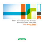
BioLogic DuoFlow System .......................................................................................................1-1
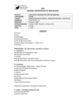
BioLogic DuoFlow Pathfinder™ System Components ............................................................2-1
MX-1 Mixer and Mixer Barrel Extender....................................................................................2-18
Maximizer Mixer and Mixer Barrel Extender............................................................................2-19
Assembly of Mixers ..................................................................................................................2-20
UV Detector, with Mercury Lamp, 254 & 280 nm Filters, and Conductivity Flow Cell.............2-21
UV Detector, with Zinc Lamp, 214 nm Filter, and Conductivity Flow Cell ...............................2-22
Conductivity Monitor.................................................................................................................2-23
QuadTec UV/Vis Detector ........................................................................................................2-24
pH Monitor................................................................................................................................2-25
AVR7-3 Sample Inject Valve ....................................................................................................2-26
Sample Load Positions ............................................................................................................2-27
Examples of AVR7-3 Valve Tubing ..........................................................................................2-28
AVR9-8 Stream Select Valve ...................................................................................................2-29
Two Examples Using AVR9-8 Valves.......................................................................................2-30
SV5-4 Buffer Select Valve........................................................................................................2-31
Two Examples Using SV5-4 Valves.........................................................................................2-32
SVT3-2 Diverter Valve..............................................................................................................2-33
Two Configurations of the SVT3-2 Valve .................................................................................2-34
BioFrac Fraction Collector .......................................................................................................2-35
Model 2110 Fraction Collector with Optional Dust Cover ........................................................2-37
Model 2128 Fraction Collector .................................................................................................2-38
DynaLoop .................................................................................................................................2-40
Plumbing the DynaLoop for use with an Inject Valve ..............................................................2-41
Model EP-1 Econo Pump.........................................................................................................2-42
EGP Econo Gradient Pump .....................................................................................................2-45
Rack Assembly.........................................................................................................................2-46
Making 1/4-28 Flat Bottom Fittings ..........................................................................................2-48
Backpressure Regulator...........................................................................................................2-49
Signal Import Module (front and rear views)............................................................................2-50
Cable Connections to the Signal Import Module .....................................................................2-50
Model 1327 Chart Recorder.....................................................................................................2-52
Example of a DuoFlow Pathfinder System Configuration........................................................3-1
DuoFlow Pathfinder Setup in Non-Condensing Environment..................................................3-2
USB Bitbus Communicator Cabling .........................................................................................3-3
System Cable Connections (without Maximizer) .....................................................................3-4
System Cable Connections (with Maximizer) ..........................................................................3-5
Rack Assembly.........................................................................................................................3-6
Mixers.......................................................................................................................................3-7
UV Detector and Conductivity Monitor.....................................................................................3-9
QuadTec Detector ....................................................................................................................3-10
Instrument Control Module (ICM).............................................................................................3-10
pH Monitor................................................................................................................................3-12
SIM Connections......................................................................................................................3-12
DuoFlow Valves .......................................................................................................................3-14
Connecting an EP-1 Econo Pump to the BioLogic DuoFlow Workstation...............................3-16
Example of Direct Inject Sample Loading using an Econo Pump ...........................................3-17
Example of Multiple Sample Loading using an Econo Pump..................................................3-17
Example of Large Sample Loading using an Econo Gradient Pump (EGP) ...........................3-18
Example of Multiple Sample Loading using an Econo Gradient Pump (EGP)........................3-18
BioLogic™ Configuration Utility Software Screen....................................................................3-20
System Plumbing using Pre-cut Tubing from Fittings Kit.........................................................4-1
Making 1/4-28 Flat Bottom Fittings ..........................................................................................4-2
System Plumbing with Maximizer ............................................................................................4-3
Maximizer Plumbing.................................................................................................................4-4
vii
TABLE OF CONTENTS
4-5.
4-6.
4-7.
5-1.
6-1.
6-2.
6-3.
6-4.
6-5.
6-6.
6-7.
6-8.
6-9.
7-1.
7-2.
7-3.
7-4.
7-5.
7-6.
7-7.
7-8.
7-9.
7-10.
7-11.
7-12.
7-13.
7-14.
7-15.
7-16.
8-1.
8-2.
8-3.
8-4.
8-5.
8-6.
9-1.
9-2.
9-3.
10-1.
10-2.
11-1.
11-2.
11-3.
11-4.
11-5.
11-6.
11-7.
11-8.
11-9.
viii
Plumbing Connections to the Workstation Pump ....................................................................4-5
Inject Valve Plumbing for an AVR7-3 .......................................................................................4-6
Backpressure Device ...............................................................................................................4-7
Layout of the Screen Display, showing the Manual Screen ....................................................5-1
The Browser Screen ................................................................................................................6-1
The CopyIn Window.................................................................................................................6-4
CopyIn with Information in Browser Tab Window ....................................................................6-5
Set Browser Options Window ..................................................................................................6-6
New Method Dialog Showing Method Templates ....................................................................6-7
Queues Displayed in the Browser Window..............................................................................6-9
Compare Displayed in the Browser Window ...........................................................................6-11
Trace Compare Window: Tiled View........................................................................................6-12
Trace Compare Window Overlay View ....................................................................................6-13
Relationships between Modes of Operation ............................................................................7-1
Manual Screen, for the BioLogic DuoFlow System Connected to a Maximizer,
BioFrac Fraction Collector, QuadTec Detector, Econo Gradient Pump, and Four Valves.......7-2
Setup Screen ...........................................................................................................................7-4
Protocol Screen........................................................................................................................7-10
Run Screen showing a Run in Progress..................................................................................7-30
Run Screen’s Abort, Pause, and Hold Buttons ........................................................................7-33
Editing during a Run ................................................................................................................7-35
Protocol Screen during a Run..................................................................................................7-36
Run Notebook Screen..............................................................................................................7-37
Run Log Screen .......................................................................................................................7-37
Post Run Screen ......................................................................................................................7-38
Post Run Tags for UV Detector................................................................................................7-40
Activity Trace Editor .................................................................................................................7-41
Activity Trace............................................................................................................................7-42
Export Data Setup Screen .......................................................................................................7-43
Exporting a Chromatographic Image .......................................................................................7-44
Multiple Sample Loading with an Auxiliary Load Pump and an AVR9-8 Valve........................8-2
Plumbing an AVR7-3 Inject Valve with an Auxiliary Load Pump..............................................8-3
AVR7-3 Valve Positions During a Run with Direct Sample Loading and Injection ..................8-4
Sample Loading through the Workstation Pump .....................................................................8-5
Plumbing the DynaLoop for use with an Inject Valve ..............................................................8-6
Valve Positions During a Run using the DynaLoop .................................................................8-8
Column Switching using Two AVR7-3 Valves ..........................................................................9-1
Column Switching using two AVR9-8 Valves ...........................................................................9-3
Reverse Flow Affinity Chromatography with an AVR7-3 Valve ................................................9-4
Buffer Blending Setup Dialog for a Single Component Buffer .................................................10-5
Buffer Blending Setup Dialog for a Multi-Component Buffer ...................................................10-5
Workstation Pump Mechanism Parts.......................................................................................11-3
Piston Assembly and Access to the Piston Seal......................................................................11-4
Pumphead Assembly ...............................................................................................................11-5
Replacing a Mercury Lamp in a Model OM-II UV Detector .....................................................11-7
Replacing a Zinc Lamp in a Model OM-II UV Detector ...........................................................11-7
Mixer Assembly ........................................................................................................................11-9
SVT3-2 Valve Assembly...........................................................................................................11-10
AVR7-3 and AVR9-8 Valve Assembly ......................................................................................11-12
Replacing a Maximizer Valve...................................................................................................11-13
TABLE OF CONTENTS
LIST OF TABLES
1-1.
2-1.
2-2.
2-3.
2-4.
2-5.
2-6.
2-7.
2-8.
2-9.
2-10.
2-11.
2-12.
2-13.
2-14.
2-15.
3-1.
4-1.
5-1.
5-2.
5-3.
5-4.
5-5.
5-6.
5-7.
5-8.
6-1.
6-2.
6-3.
6-4.
6-5.
6-6.
7-1.
7-2.
7-3.
7-4.
7-5.
7-6.
7-7.
7-8.
7-9.
7-10.
7-11.
7-12.
7-13.
9-1.
10-1.
B-1.
DuoFlow System Configurations..............................................................................................1-4
Front View of the Dell PC Computer as the DuoFlow Controller.............................................2-2
Rear View of the Dell PC Computer as the DuoFlow Controller .............................................2-4
USB Bitbus Communicator ......................................................................................................2-5
F10 and F40 Pumphead Flow Rates .......................................................................................2-6
Workstation Front Panel Controls ............................................................................................2-7
Workstation Rear Panel Connectors........................................................................................2-9
Maximizer Front Panel Controls...............................................................................................2-12
Maximizer Rear Panel Connectors ..........................................................................................2-14
Maximizer Screens...................................................................................................................2-16
Mixer Barrels and Mixer Capacity for the MX-1 Mixer .............................................................2-18
Mixer Barrels and Mixer Capacity for the Maximizer Mixer .....................................................2-19
BioFrac Racks Available ..........................................................................................................2-36
Model 2128 Racks Available....................................................................................................2-38
Workstation Pump Configuration Flow Rates ..........................................................................2-51
Columns and Column Fittings..................................................................................................2-58
Mixer Flow Rates .....................................................................................................................3-7
Tubing Guidelines ....................................................................................................................4-2
Special Function Keys .............................................................................................................5-2
Toolbar Buttons ........................................................................................................................5-3
File Drop-down Menu...............................................................................................................5-5
Edit Drop-down Menu ..............................................................................................................5-7
View Drop-down Menu.............................................................................................................5-9
Utilities Drop-down Menu .........................................................................................................5-10
Options Drop-down Menu ........................................................................................................5-11
Window Drop-down Menu........................................................................................................5-12
Toolbar Buttons ........................................................................................................................6-14
File Drop-down Menu...............................................................................................................6-15
Options Drop-down Menu ........................................................................................................6-15
View Drop-down Menu.............................................................................................................6-16
Tools Drop-down Menu ............................................................................................................6-16
Window Drop-down Menu........................................................................................................6-16
Valve Setup Information ...........................................................................................................7-7
Buffer Editor .............................................................................................................................7-9
Isocratic Flow ...........................................................................................................................7-11
Load/Inject Sample ..................................................................................................................7-12
Linear Gradient ........................................................................................................................7-15
Change Valve...........................................................................................................................7-16
Column Switching ....................................................................................................................7-17
Hold ..........................................................................................................................................7-18
Miscellaneous Buttons .............................................................................................................7-19
Fraction Collection Button........................................................................................................7-20
Scouting ...................................................................................................................................7-25
Protocol Screen’s Editing Toolbar Buttons...............................................................................7-29
Run Screen’s Control Buttons..................................................................................................7-32
Common Multidimensional Chromatography Experiments......................................................9-5
Buffer Blending Buffer Systems ...............................................................................................10-2
Pressure Conversion................................................................................................................B-1
ix
SYSTEM OVERVIEW
INTRODUCTION
1.0
INTRODUCTION
1.1
OVERVIEW
The BioLogic DuoFlow chromatography system is specifically designed for the high resolution purification of
proteins, peptides, and other biomolecules where recovery of biological activity is of primary concern. The
DuoFlow F10 pumphead operates at up to 20 ml/min and 3500 psi (233 bar, 23 MPa) when used with the
Maximizer. The DuoFlow F40 pumphead operates at up to 80 ml/min and 1000 psi (66 bar, 6.6 MPa) when
used with the Maximizer.
The BioLogic DuoFlow system software provides an easy-to-use graphic interface and menu-driven software
for manual operation, system setup, method editing, and run operations. The system software may be run
on any PC running Microsoft® Windows® 2000.
The flexible control architecture allows the seamless integration of a wide variety of configurations with other
Bio-Rad and non-Bio-Rad components to meet your purification requirements.
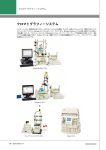
UNO
TM
Q1 COLUMN
AVR7-3 SAMPLE
INJECT VALVE
QUADTEC DETECTOR
pH MONITOR
MAXIMIZER MIXER
USB BITBUS COMMUNICATOR
CONDUCTIVITY
MONITOR
WORKSTATION
BioFrac Franction Collector
F1
A
KEYBOARD
F3
F4
F5
1
2
3
4
5
6
7
8
9
0
B
VALVE A
DELL CONTROLLER
F2
VALVE B
MAXIMIZER
BIOFRAC
MOUSE
Figure 1-1. BioLogic DuoFlow System
1-1
INTRODUCTION
1.2
SYSTEM OVERVIEW
FEATURES
BioLogic DuoFlow systems provide the following features:
1-2
•
Setup Flexibility. A space saving modular design that is stackable and easily configured to meet
your exact needs and fit into your desired bench space. Trays and vertical bars are moveable and
removable. Horizontal bars can be placed in the optimal position for valves, columns, detectors, etc.
The system fits easily into a cold box.
•
Modular components provide an easy upgrade path to fit all applications and financial
requirements. For example, the BioLogic DuoFlow™ Basic system may be purchased and upgraded
to a BioLogic DuoFlow QuadTec™, BioLogic DuoFlow Maximizer or BioLogic DuoFlow Pathfinder
system as needed. (See Section 1.4 for a description of the DuoFlow systems and upgrades.)
•
Intuitive, user-friendly software programming. Users become an expert in only a few runs.
• Four easy steps to set up new devices/instruments, create a new method, and start to run
samples:
Step 1. Browser, to enter new user name, project name and method name.
Step 2. Setup, to specify devices required for the method.
Step 3. Protocol, to enter sequential method steps.
Step 4. Run, to inject sample and view the real time chromatogram.
• Two easy steps, if you want to run a sample using a current Setup and Protocol:
Step 1. Browser, to select a user and along with a method or Method Template.
Step 2. Run, to inject sample and view real time chromatogram.
•
On screen Help. Includes detailed information and a troubleshooting guide.
•
USB Bitbus Communicator. The USB Bitbus communicator allows the BioLogic DuoFlow system
to be controlled from any computer running Windows 2000 and BioLogic software 4.0 or above, over
a USB port.
•
Buffer Blending. Buffer Blending is a feature of the BioLogic DuoFlow Maximizer™ and Pathfinder
systems that dynamically "Blends" the conjugate acid and base of a buffer with water and salt to
produce a solution with a specific salt concentration and pH.
•
Buffer Editor. The Buffer Editor is a feature used to create buffer systems for use in Buffer Blending
experiments. Both single and multiple component buffers can be created.
•
Scouting. This feature facilitates the optimization of a chromatography protocol for a specific target
molecule. Scouting systematically increments a user selected variable and then performs a
chromatography run at each increment. Variables that can be "Scouted" include: pH, %B, step
duration, column, buffer, flow rate, sample and sample volume.
•
Method Templates. Includes ready-to-run chromatography protocols for a variety of experiment
types including: affinity, chromatofocusing, hydroxyapatite, hydrophobic interaction, ion exchange
and gel filtration chromatography.
•
pH Monitor. The BioLogic pH monitor allows direct pH monitoring during a run. It is included as part
of the DuoFlow Maximizer and Pathfinder systems and is available as an option for all other system
configurations. The pH monitor consists of a Calomel Tris compatible electrode in a PEEK
biocompatible flow cell.
•
Flow Rate Flexibility. The DuoFlow Workstation has two pump head options (F10 and F40) that
permit a wide range of flow rates (0.01 ml/min up to 80 ml/min).
•
Detection Flexibility
• UV detector with fixed 254 nm and 280 nm filters, long life mercury lamp, and additional drop-in
expansion filters available.
• UV detector can be expanded to 214 nm filter with zinc lamp.
• QuadTec UV/Vis detector analyzes samples simultaneously at 4 different wavelengths from 190370 nm with a deuterium lamp or 370-790 with a halogen lamp.
SYSTEM OVERVIEW
•
1.3
INTRODUCTION
Third party detectors, such as refractive index or fluorescence, may be utilized with the DuoFlow
systems via a Signal Import Module (SIM) or Maximizer.
•
Conductivity Monitor. Monitors salt concentration to assure reliable gradient formation and pump
function.
•
Fraction Collection. The DuoFlow system supports a wide variety of fraction collection options
including: Collect All, Threshold Collection, Collection Windows and Threshold & Collection
Windows. Both Above Threshold and Below Threshold collection are supported. The software also
supports tube numbering by Rack & Tube # and Rack & Grid #.
•
Multiple Valve Capabilities
• Workstation provides connection for 3 low pressure and 3 high pressure valves.
• Workstation with the addition of the Maximizer doubles the capacity to 6 low pressure and 6
high pressure valves.
•
Starter Kit and UNO Q1 Anion Exchange Column. Includes the necessary reagents, protein
sample and columns for running an anion exchange chromatography experiment. The kit includes
easy to follow, tutorial style instructions for the first time user.
•
IQ/OQ Protocols. Validation protocols are available or can be performed by certified Bio-Rad
service engineers.
UNPACKING
When you receive the BioLogic DuoFlow system, carefully inspect the shipping containers for any damage
which may have occurred in shipping. Severe damage to a container may indicate damage to its contents. If
you suspect damage to the contents, immediately file a claim with the carrier in accordance with their
instructions before contacting Bio-Rad Laboratories.
!
Caution
Lift items from the bottom as you remove them from their containers!
Open each of the shipping cartons and lift the contents out of its packing. Check the contents of each box
against the supplied packing list. Remove the plastic bag from each unit and inspect the unit for external
damage. If any part is missing or damaged, contact Bio-Rad Laboratories immediately.
Bio-Rad ships DuoFlow systems in a number of different configurations, each with its own catalog number.
These systems are described in the following table. Because of its modular design, any of these systems
can be upgraded any time simply by adding system options.
1-3
INTRODUCTION
1.4
SYSTEM OVERVIEW
SYSTEM CONFIGURATIONS
F10 Pump Kit
F40 Workstation
F40 Pump Kit
BioFrac
Fraction Collector
QuadTec UV/Vis
Detector
Maximizer (incl pH)
pH Monitor
760-0037
760-0036
760-0038
DuoFlow Basic System 100/120 V
DuoFlow Basic System Japan and Korea
DuoFlow Basic System 220/240 V
10 ml/min flow rate to 3500 psi
254/280 nm detection
S
S
U
U
U
U
U
U
760-0047
760-0046
760-0048
DuoFlow Standard System 100/120 V
DuoFlow Standard System Japan/Korea
DuoFlow Standard System 220/240 V
10 ml/min flow rate to 3500 psi
254/280 nm detection
Fraction collection
S
S
U
U
S
U
U
U
760-1137
760-1136
760-1148
DuoFlow QuadTec Basic System 100/120 V
DuoFlow QuadTec Basic System Japan/Korea
DuoFlow QuadTec Basic System 220/240 V
10 ml/min flow rate to 3500 psi
UV/Vis detection with 4 simultaneous wavelengths
S
S
U
U
U
S
U
U
760-1147
760-1146
760-1148
DuoFlow QuadTec Standard System 100/120 V
DuoFlow QuadTec Standard System Japan/Korea
DuoFlow QuadTec Standard System 220/240 V
10 ml/min flow rate to 3500 psi
UV/Vis detection with 4 simultaneous wavelengths
Fraction collection
S
S
U
U
S
S
U
U
760-2237
760-2236
760-2238
DuoFlow Maximizer 20 System 100/120 V
DuoFlow Maximizer 20 System Japan/Korea
DuoFlow Maximizer 20 System 220/240 V
20 ml/min flow rate to 3500 psi
254/280 nm detection
Buffer blending
Fraction collection
S
S
U
U
S
U
S
S
760-2247
760-2246
760-2248
DuoFlow Maximizer 80 System 100/120V
DuoFlow Maximizer 80 System Japan/Korea
DuoFlow Maximizer 80 System 220/240 V
80 ml/min flow rate to 1000 psi
254/280 nm detector
Buffer blending
pH monitoring
Fraction collection
U
U
S
S
S
U
S
S
760-2257
760-2256
760-2258
DuoFlow Pathfinder 20 System 100/120 V
DuoFlow Pathfinder 20 System Japan/Korea
DuoFlow Pathfinder 20 System 220/240 V
20 ml/min flow rate to 3500 psi
UV/Vis detection with 4 simultaneous wavelengths
Buffer blending
pH monitoring
Fraction collection
S
S
U
U
S
S
S
S
760-2267
760-2266
760-2268
DuoFlow Pathfinder 80 System 100/120 V
DuoFlow Pathfinder 80 System Japan/Korea
DuoFlow Pathfinder 80 System 220/240 V
80 ml/min flow rate to 1000 psi
UV/Vis detection with 4 simultaneous wavelengths
Buffer blending
pH monitoring
Fraction collection
U
U
S
S
S
S
S
S
Catalog Number
F10 Workstation
The BioLogic DuoFlow is available in the following system configurations. Each system configuration is
identified by its name, its standard components and devices, and optional components and devices that may
be ordered separately for use with the system.
1-4
BioLogic DuoFlow System Guide
S = Standard
U = Upgradable
SYSTEM OVERVIEW
1.5
INTRODUCTION
QUICK START PROCEDURE
The general procedure used to create and run a chromatography experiment on a DuoFlow system is
described below.
1.
Install the required devices and instruments on the system (see Figures 3-4 and 5-5 for cable
connections and 4-1 and 4-3 for plumbing connections).
2.
Flush all plumbing with DDI H2O to ensure that the system is clean and free of air and then prime
the pumps with starting buffer. See Chapter 4 for more detail.
3.
Attach a column and set the pressure limits in the Manual screen. The high limit should be less than
or equal to the pressure limit for the column.
4.
Equilibrate the column and system with starting buffer. System equilibration is controlled from the
Manual screen (see Section 7.1).
5.
Create a new method in the Browser.
a.
Start the Browser using the Browser button on the tool bar and then select or create a user
and project. Refer to Chapter 6 for more information on the Browser screen.
b.
Use the New or New/New User option in the Browser tools, on the left side of the screen, to
create a new user and enter a username.
c.
Use the New and New Method option in the Browser tools to create and name a new method.
Click OK to proceed to the hardware Setup screen. Alternatively, check the Use Method
Templates box, select a method template and press OK.
6.
In the Device Setup screen, select the devices that are connected to the system. Select the
File/Save Setup menu item and save the device setup (check the Default Setup box if this is the
default setup). Refer to Section 7.2 for more information about the Device Setup screen.
7.
Start the Protocol Editor using the tool bar Protocol Editor button. Use the protocol screen Add Step
tools to create a new method as illustrated with below for an ion exchange protocol. See Chapter 7
for more information.
a.
Add an Isocratic Flow step to equilibrate the column and enter the required flow rate, step
size and %B. The parameters entered here will automatically appear in the next step, but can
be changed at any time.
b.
Add a Zero Baseline step to zero the selected detector prior to sample injection.
c.
Add a Load Inject Sample step and then enter the sample inject volume and flow rate. If a
static injection loop is used with an AVR7-3 Sample Inject Valve select static loop. For
information about the other injection options see Chapter 8.
d.
Add an Isocratic Flow step to wash the column and enter the required flow rate, step size and
%B.
e.
Add a Linear Gradient step to elute the column and enter the required flow rate, step size,
initial %B and final %B.
f.
Add an Isocratic Flow step to clean the column and enter the required flow rate step size and
%B (usually 100%). This ensures that the entire sample is removed from the column.
g.
Add an Isocratic Flow step to re-equilibrate the column and enter the required flow rate step
size and %B (see step a, above).
h.
Add a Fraction Collection step to specify how fractions are to be collected for the experiment.
Enter the collection technique (e.g. collect all, threshold, etc), fraction size and any required
threshold or collection windows parameters. Note that the dialog displays the number of tubes
required for the currently defined protocol.
8.
Press the New Run button to create a new run, enter a run name and open the Run screen.
9.
Set the appropriate pressure limits for the column being used and then press Start on the system
tool bar. Refer to Chapter 7.4 for more information about the Run screen.
1-5
SYSTEM OVERVIEW
2.0
DESCRIPTION OF SYSTEM COMPONENTS
DESCRIPTION OF SYSTEM COMPONENTS
The DuoFlow’s modular design supports many types of system components, and allows for a wide variety of
system configurations. This section discusses in detail the function of each component and its connection to
the system.
•
Dell PC Computer/Controller and USB Bitbus Communicator (Section 2.1)
•
Workstation (Section 2.2)
•
Maximizer (Section 2.3)
•
Mixers: MX-1 and Maximizer mixers: (Section 2.4)
•
Detection Systems: UV detector, Conductivity monitor, pH monitor, and QuadTec detector:
(Section 2.5)
•
Valves: AVR7-3, AVR9-8, SV5-4, and SVT3-2 valves: (Section 2.6)
•
Fraction Collectors: BioFrac, Model 2128, and Model 2110: (Section 2.7)
•
Sample Loading Options: DynaLoop, EP-1 Econo pump, and EGP Econo Gradient Pump:
(Section 2.8)
•
System peripherals: (Section 2.9)
•
Columns and Column Fittings: (Section 2.10)
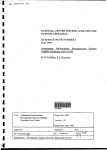
UNO
TM
Q1 COLUMN
AVR7-3 SAMPLE
INJECT VALVE
QUADTEC DETECTOR
pH MONITOR
MAXIMIZER MIXER
USB BITBUS COMMUNICATOR
CONDUCTIVITY
MONITOR
WORKSTATION
BioFrac Franction Collector
F1
A
KEYBOARD
F3
F4
F5
1
2
3
4
5
6
7
8
9
0
B
VALVE A
DELL CONTROLLER
F2
VALVE B
MAXIMIZER
BIOFRAC
MOUSE
Figure 2-1. BioLogic DuoFlow Pathfinder System Components
2-1
DESCRIPTION OF BIOLOGIC DUOFLOW SYSTEM
2.1
SYSTEM OVERVIEW
CONTROLLER AND USB BITBUS COMMUNICATOR
The DuoFlow system is controlled by a PC computer, referred to throughout this document as the Controller.
The Dell Controller available from Bio-Rad includes a color display monitor, a keyboard, a mouse device, a
CD-ROM drive, and a floppy disk drive. The Controller communicates with the workstation and other
external devices through its USB connector. The USB Bitbus Communicator serves as the link between the
Controller’s USB port and the DuoFlow’s instrument bus. This link allows the Controller to control the
Maximizer and Workstation, as well as any devices connected to the Maximizer or Workstation, such as
automatic valves, UV detector and conductivity monitor, and peripheral instruments such as the BioFrac
fraction collector, the QuadTec UV/Vis detector, the Model EP-1 Econo pump, the Econo Gradient Pump
(EGP), and Signal Import Modules (SIM).
2.1.1 Controller
The Controller runs the BioLogic DuoFlow software (version 4.0 or higher) on a Windows® 2000 operating
system. From the Controller you can set up and run methods, perform simple data analysis, and store
method and run data. The following tables show the key features on the Dell computer provided by Bio-Rad.
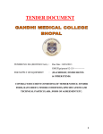
Table 2-1.
Front View of the Dell PC Computer as the DuoFlow Controller
COLOR DISPLAY MONITOR
POWER SWITCH
CD-ROM DRIVE
USB CONNECTORS (2)
(BEHIND COVER PANEL)
Feature
Power Switch
Floppy
Disk Drive
2-2
FLOPPY DISK DRIVE
Description
Turns on/off the Controller and monitor.
To backup methods to - and restore methods from - a floppy disk. Press the button
next to the drive slot to manually eject a floppy disk from the drive.
SYSTEM OVERVIEW
DESCRIPTION OF BIOLOGIC DUOFLOW SYSTEM
Table 2-1. (continued)
Front View of a Dell PC Computer as the DuoFlow Controller
Feature
Description
CD ROM Drive
To load updates of the BioLogic DuoFlow operating software. To open the drive,
press the button on the front of the drive.
Keyboard,
Mouse, &
Function Keys
The keyboard and mouse interface devices control the system. They are standard
PC compatible input devices. The keyboard includes the following special function
keys:
F2
Hold until Keypress: To start a method that is on Hold during a run when a
method includes a “Hold until Keypress” step.
F1
Help: Displays the Help menu for the currently displayed screen.
Esc
Alt
USB Connectors
Esc: Functions as an alternative to the Cancel selection in a Dialog box.
Alt: Some system commands can be executed either by selecting them from a
drop-down menu or by holding down the Alt key and then pressing the
appropriate character key.
These connect to the USB Bitbus Communicator, which in turn connects to the
instrument bus, and allows components of the BioLogic DuoFlow system to
communicate with the Controller. Components connect to the instrument bus in a
“daisy-chain” and are recognized when the system is switched on. Even when one
component is switched off, other components “daisy-chained” to the system can be
controlled by the Controller.
2-3
DESCRIPTION OF BIOLOGIC DUOFLOW SYSTEM
SYSTEM OVERVIEW
Table 2-2.
Rear View of the Dell PC Computer as the DuoFlow Controller
MONITOR POWER
CONNECTOR
DELL CONTROLLER
MONITOR
SIGNAL CABLE
ETHERNET
CONNECTOR
MOUSE
CONNECTOR
COLOR MONITOR
CONNECTOR
KEYBOARD
CONNECTOR
USB BUS CONNECTORS
PARALLEL
CONNECTOR
CONTROLLER
POWER CONNECTOR
Connector
Description
USB connectors: These connect to the USB Bitbus Communicator, which in turn
connects to the instrument bus, and allows components of the BioLogic DuoFlow
system to communicate with the Controller. Components connect to the instrument
bus in a “daisy-chain” and are recognized when the system is switched on. Even
when one component is switched off, other components “daisy-chained” to the system
can be controlled by the Controller.
Monitor connector: To connect the color monitor to the Controller.
Keyboard connector: To connect the keyboard to the Controller.
Mouse connector: To connect the mouse to the Controller.
Parallel connector: Devices designed for connection to the parallel port include
printers and external storage devices. Refer to Windows® 2000 and/or the device
documentation for installation instructions. (Some printer drivers are pre-installed on
the Controller.)
Power connectors: To connect the power cable.
2-4
SYSTEM OVERVIEW
2.1.2
DESCRIPTION OF BIOLOGIC DUOFLOW SYSTEM
USB Bitbus Communicator
The USB Bitbus Communicator is used to connect the Controller to DuoFlow system instrument bus and to
supply power to the instrument bus when a Signal Import Module (SIM) is used
Table 2-3.
USB Bitbus Communicator
POWER
USB
PWR
SELECT
BUS
PWR
INSTR BUS
ON
EXT
INT
+5V
FRONT VIEW
Feature
USB
REAR VIEW
Description
Used to connect to the Controller USB port by way of a USB cable (catalog number
760-2032).
ON LED
Indicates that there is power to the USB Bitbus Communicator.
POWER
Is used to supply power to the USB Bitbus Communicator when a Signal Import
Module (SIM) is connected to DuoFlow instrument bus. The universal AC/DC inline
adapter (catalog number 760-2034) must be used to supply the power. Use of other
power adapters may damage the USB Bitbus Communicator.
PWR SELCT
Used to select whether power for the USB Bitbus Communicator is drawn from the
Controller (INT) or the AC/DC inline adapter (EXT). An external power source must
be used if a Signal Import Module (SIM) is connected to the instrument bus
otherwise it is not required.
BUS PWR
Indicates that the instrument bus is receiving power from an external power source.
The light is off when the PWR SELCT switch is set to INT. The light will turn on
when the USB Bitbus Communicator is switched to EXT and power is being
received.
LED
INSTR BUS
Used to connect the USB BitBus Communicator to the DuoFlow instrument bus.
2-5
DESCRIPTION OF BIOLOGIC DUOFLOW SYSTEM
2.2
SYSTEM OVERVIEW
WORKSTATION
The Workstation contains the following:
•
Dual pumpheads, each consists of two biocompatible dual piston pumpheads. A built-in pressure
transducer is located on the workstation at the pump outlet. The pressure transducer measures
system pressure, which is displayed on the lower status bar of the software Manual and Run
screens. Purge and Pause buttons (Purge A, Purge B, and Pause) are present on the front of the
Workstation.
There are two types of pumpheads; the F10 and the F40. All DuoFlow systems have F10
pumpheads, except DuoFlow Maximizer 80 and DuoFlow Pathfinder 80 systems that have F40
pumps.
F10 and F40 pumphead kits are available to easily convert an F10 Workstation to F40 and vise versa.
(See Section 2.9.7)
Table 2-4.
F10 and F40 Pumphead Flow Rates
2-6
Pumphead
Flow Rate:
Isocratic and
Gradient Mode
Flow Rate
with Maximizer:
High Flow Non-blending
Flow Rate
with Maximizer:
Buffer Blending Mode
F10
0.01 - 10 ml/min
3500 psi
(233 bar, 23 MPa)
0.02 - 20 ml/min
3500 psi
(233 bar, 23 MPa)
0.5 - 20 ml/min
3500 psi
(233 bar, 23 MPa)
F40
0.5 - 40 ml/min
1000 psi
(66 bar, 6.6 MPa)
1.0 - 80 ml/min
1000 psi
(66 bar, 6.6 MPa)
1.0 - 80 ml/min
1000 psi
(66 bar, 6.6 MPa)
•
The Workstation houses the control circuitry for the Workstation pumps, MX-1 mixer, UV detector,
Conductivity monitor, and system valves (low pressure solenoid and automated high pressure inject
and select valves). Connectors on the rear panel provide inputs for valves and detectors, as well as
output to a chart recorder for UV and conductivity data at 1 V Full Scale and pen up/down, start/stop
control.
If a Maximizer is being used, connect devices to it to connect the mixer, Conductivity monitor, and
pH monitor to it, rather than to the Workstation.
•
An AUX combicon connector used for (a) controlling fraction advances of the Model 2110 and
generic fraction collectors, (b) receiving an open/closed signal from a device such as a manual inject
valve, and (c) starting and stopping the Model EP-1 Econo pump for sample loading.
If a Maximizer is being used, connect these devices to its AUX connector, rather than to the
Workstation.
•
Power supply for the Workstation electronics as well as all devices connected to and controlled by
the Workstation.
•
Output power connectors to the UV lamp and a Model 1327 chart recorder.
•
Two instrument bus (phone-type) connectors.
SYSTEM OVERVIEW
DESCRIPTION OF BIOLOGIC DUOFLOW SYSTEM
Table 2-5.
Workstation Front Panel Controls
PUMPHEAD WASHOUT
INLET PORTS
PRIMING PORT A
PRESSURE
TRANSDUCER
INLET PORTS
PRESSURE TRANSDUCER
OUTLET PORT
BioLogic DuoFlow Workstation
PUMPHEAD OUTLET
PORTS
PAUSE
PRIMING PORT B
ALERT LEDs
POWER
WASHOUT OUTLET
A
B
INLET PORTS A & B
PURGE
Feature
Description
Power Button
Turns power on/off to the Workstation and to the components connected to it.
Pause Button
Stops the Workstation pumps and pauses a running method. When it is pressed, the
status LEDs for pumps A and B change from green to flashing red. To resume the
run,
• Press the button again, to restarts the pumps and the method, or
• Press the Continue button in the Run screen, or
• Press the START button in the Manual screen.
Purge A & B
Buttons
Before you press either purge button switch the AVR7-3 inject valve to the Purge
position in the Manual screen, so that the column is not exposed to high pressures
and flow rates.
The purge buttons flush the tubing lines with the solution connected to pumps A and
B. When the buttons are pressed, the green LEDs for pumps A and B flash. To stop
the flow, press the purge buttons again and the LEDs go off. These buttons do not
operate when the system is running a method.
When the purge buttons are pressed, the pumpheads run at their (default)
maximum flow (F10 purge rate is 10.0 ml/min or 20 ml/min when used with the
Maximizer; F40 purge rate is 40 ml/min or 80 ml/min when used with the
Maximizer.) To alter the default purge flow rate, select Manual Setup from the
Options drop-down menu.
Alert Light
This LED serves two functions:
a.
Constant red: Indicates that the pump has shut down due to a mechanical or
electrical problem. This includes a shutdown due to a high or low pressure
limit being exceeded. Pressure limits are set in the Manual and Run screens.
b.
Flashing red: Occurs during a method run and indicates that a pre-programmed
ALARM step has been reached. The system operator must respond before the
method continues. Also, the Controller emits an audible tone.
c.
Constant green: Indicates the pump is running.
2-7
DESCRIPTION OF BIOLOGIC DUOFLOW SYSTEM
SYSTEM OVERVIEW
Table 2-5. (continued)
Workstation Front Panel Controls
Description
Feature
Plumbing
Connections
Ports on the front of the Workstation:
a.
Pumphead Inlet ports: Buffer inlet lines attach to the bottom of each
pumphead using standard 1/4-28 flat-bottom fittings. The pumphead inlet
tubing is 1/8” (3.2 mm) OD, 0.062” (1.6 mm) ID PTFE tubing with flat bottom
fittings which are supplied in the Fittings kit.
b.
Pumphead Outlet and Pressure Transducer Inlet and Outlet ports: All
plumbing following the pumphead outlet ports uses standard 1/4-28 flatbottom fittings and the following tubing:
Orange PEEK tubing: 1/16” (1.6 mm) OD, 0.020” (0.51 mm) ID. Used with
pressures up to 5000 psi.
Green PEEK tubing: 1/16” (1.6 mm) OD, 0.030” (0.76 mm) ID. Used with
pressures up to 3000 psi, usually for flow rates greater than 20 ml/min.
c.
d.
2-8
Pumphead Priming ports: This port on each pumphead is used to prime the
pump. The port accepts any size syringe with a luer fitting; a syringe is
included in the Fittings kit. This draws buffer through the inlet line and to the
pumphead. Twist the port counter-clockwise one turn to open it.
Pumphead Washout Inlet ports: The port on top of each pumphead is used
to rinse the piston to remove crystallized salts. It accepts any syringe with a
luer fitting. A syringe for this purpose is included in the Fittings kit. The rinse
output is the open trough between the pumpheads. The pumpheads should br
rinsed daily.
SYSTEM OVERVIEW
DESCRIPTION OF BIOLOGIC DUOFLOW SYSTEM
6
UV LAMP
Connector
10..25V
2
3
1. INJECT
2. n/c
3. n/c
4. n/c
5. FC ADV
6. AUX PUMP
7. n/c
8. n/c
9. GND
INSTR. BUS
5
AUTOMATED VALVES
1
MIXER
4
SOLENOID VALVES
Table 2-6.
Workstation Rear Panel Connectors
UV
CHART
COND
CHART
UV
OPTICS
COND
FLOWCELL
0.3A MAX.
Description
Solenoid Valves: To connect DuoFlow low pressure solenoid valves (SV5-4 and
SVT3-2) to the system. If a Maximizer is in use, connect to its solenoid valve
connectors before those on the Workstation.
Automated Valves: To connect DuoFlow high pressure automated valves (AVR7-3
Inject and AVR9-8 Stream Select) to the system. If a Maximizer is in use, connect
to its automated valve connectors before those on the Workstation.
Cond Flowcell: To connect the Conductivity monitor flow cell to the system. If the
Maximizer is being used, you must use its Cond Flowcell connector rather than the
connector on the Workstation.
UV Lamp: This specialized 6-pin square connector provides electrical power to the
mercury or zinc lamp in the UV detector lamp housing. This connector is not
available on the Maximizer.
UV Optics: To connect the UV detector to the system.
Mixer: To connect the mixer to the system. If the Maximizer is in use, connect to its
mixer connector before those on the Workstation.
10...25V --0.3A Max: Provides electrical power to the Model 1327 chart recorder or
Instrument Control Module (ICM).
Cond Chart: For conductivity signal output to a single or dual pen chart recorder.
An 8-pin mini-DIN to banana plug cable (System Cable 4) for connection to the
Model 1327 chart recorder is available. Connect the red line to the positive (+)
terminal and the black line to the negative (–) or ground terminal of channel 2 (CH2).
The chart recorder should be set to 1 V full scale. If you are using the Model 1327
chart recorder, move all switches to the “green” settings.
2-9
DESCRIPTION OF BIOLOGIC DUOFLOW SYSTEM
SYSTEM OVERVIEW
Table 2-6. (continued)
Workstation Rear Panel Connectors
Description
Conector
UV Chart: For UV signal output to a single or dual pen chart recorder. When the
Bio-Rad Model 1327 is used, chart recorder Pen Up/Down, Stop/Start commands,
and event marks are sent from this connector.
The Bio-Rad Model 1327 dual pen recorder needs an 8-pin mini-DIN to standard DIN
cable (System Cable 2) and a mini-DIN to banana plugs cable (System Cable 4).
Generic chart recorders require an 8-pin mini-DIN to breakout cable (System Cable 7),
available from Bio-Rad.
When a Signal Import Module signal replaces the standard BioLogic UV Detector,
use System Cable 20 to control a Bio-Rad Model 1327 dual pen chart recorder.
The chart recorder should be set to 1V.
Power Cord: The grounded 3-prong connector inputs power to the Workstation
and outputs power to any unit connected to the Workstation. The Workstation’s
input power cord should be plugged into a 3-prong grounded power outlet.
AUX PORT
Instr Bus: The RJ-45 modular phone connectors and the bus communication cables
connect the Workstation to the other components in the system. The Instrument Bus
handles all communications between the Controller and each of the components in
the system. For example, the Instrument Bus connects the Workstation to the USB
Bitbus Communicator, Maximizer, BioFrac fraction collector, or Econo Gradient
Pump. Components can be connected to the system in any order.
1 INJECT
2 N/C
3 N/C
4 N/C
5 FC ADV
6 AUX PUMP
7 N/C
8 N/C
9 GND
Aux: The 9-pin AUX PORT connects a variety of peripheral modules that cannot
communicate with the DuoFlow Controller over the Instrument Bus. If the Maximizer
is being used, use its AUX connector before the connector on the Workstation.
Pin #
1
2
3
4
5
6
7
8
9
Description
Inject. A contact closure between pins 1 and 9 (GND) satisfies a Hold
command which has been programmed in a method protocol.
n/c. No connection
n/c. No connection
n/c. No connection
FC Adv. Model 2110 and generic fraction collector Advance output.
AUX Pump. A Stop-Start command is sent to a pump (e.g., Bio-Rad EP-1).
n/c. No connection
n/c. No connection
GND. Ground
Reserved for internal Bio-Rad use.
2-10
SYSTEM OVERVIEW
2.3
DESCRIPTION OF BIOLOGIC DUOFLOW SYSTEM
BIOLOGIC MAXIMIZER VALVE SYSTEM
The Maximizer enables buffer blending applications, doubles the accessible pump flow rate, and doubles
valving capacity to 6 low pressure valves and 6 high pressure valves. The Maximizer includes a separate
Maximizer mixer (see Section 2.4.2) and pH monitor (see Section 2.5.4).
•
Proportioning valves on the Maximizer blend water, salt, and the conjugate acid and base of a buffer
to obtain a solution with a user-defined pH and salt concentration. One valve delivers an acid and
base and the other valve delivers a salt and water.
•
Pre-defined Buffer Blending buffer systems are provided for virtually all common buffers used in
chromatographic applications. Additional user-defined buffers may be created using the BioLogic
software Buffer Editor feature. The Maximizer uses the buffer system information to determine the
amount of acid, base, water and salt to add to obtained the desired buffer composition and pH.
•
When the Maximizer is set to local mode in the software Manual screen, it will not be under
DuoFlow system control. In local mode the Maximizer front panel controls are accessible and can be
used to prime the system, calibrate the pH and conductivity monitor, observe the status of each
device, and control the position of each Maximizer valve.
•
The Maximizer is designed to operate under normal laboratory and coldroom conditions (4° - 40° C)
with all commonly used aqueous chromatographic buffers.
The Maximizer includes the following hardware and circuitry:
•
Front panel: on/off switches; two 3-port, two position proportioning valves for automated buffer
blending; an LCD screen and membrane switches for controlling valve positions and calibrating the
pH probe and conductivity monitor.
•
Rear panel: connectors that (with the exception of the UV detector) duplicate the connectors on the
Workstation. It is recommended that valves, peripheral devices, and flow cells be connected to the
Maximizer rather than the Workstation unless more valving capability is needed.
2-11
DESCRIPTION OF BIOLOGIC DUOFLOW SYSTEM
SYSTEM OVERVIEW
Table 2-7.
Maximizer Front Panel Controls
LCD DISPLAY
VALVES A & B
ARROW
KEYS
VALVE A
VALVE B
A1
A2
B1
B2
ACID
BASE
WATER
SALT
ENTER
KEY
VALVE
INLET
SELECT
BUTTONS
POWER
ON/OFF
VALVE INLET
STATUS LEDs
SOFT KEYS
Description
Feature
Power On/Off
Controls power to the unit.
Valves A & B
Proportioning valves used for Buffer Blending and inlet selection. Each valve has
two inlet ports and one outlet port. For Buffer Blending, acid is placed at inlet A1,
base at inlet A2, water at inlet B1 and salt and inlet B2. The valve outlet ports are
connected directly to their respective Workstation pump inlet ports. Color-coded
tubing is supplied with the Maximizer for plumbing the inlet ports (A1 = red, A2 =
blue, B1 = yellow and B2 = green).
Valve Inlet
Select Buttons
Valve Inlet
Status LEDs
LCD Display
2-12
Used when the Maximizer is in Local mode to change the position of valves A and B.
Indicates which valve port is open.
Displays the Maximizer status. When the Maximizer is operated from its front panel
controls, the LCD displays status and control information, including valve positions, pH
and conductivity calibration information, and current temperature.
SYSTEM OVERVIEW
DESCRIPTION OF BIOLOGIC DUOFLOW SYSTEM
Table 2-7. (continued)
Maximizer Front Panel Controls
Feature
Softkeys
Enter and Arrow
Keys
Description
For limited local operation of the Maximizer. This is discussed further in Table 2-9.
To operate the Maximizer in conjunction with the softkeys, as discussed above.
2-13
DESCRIPTION OF BIOLOGIC DUOFLOW SYSTEM
SYSTEM OVERVIEW
Table 2-8.
Maximizer Rear Panel Connectors
SV PORT 7
SV PORT 8
SV PORT 9
AV PORT 10
AV PORT 11
9 GND
pH
8
SIM
7
COND
6 AUX PUMP
INSTR. BUS
5 FC ADV
COM2
4
COM1
3
MIXER
2
1 INJECT
100-240V 2 - 2A MAX
50 - 60 Hz
POWER ENTRY
AUX PORT
AV PORT 12
ATC
MAXIMIZER REAR
Description
Connector
Solenoid Valves: To connect DuoFlow low pressure solenoid valves (SV5-4
and SVT3-2) to the system. If a Maximizer is in use, connect to its solenoid
valve connectors before those on the Workstation.
Automated Valves: To connect DuoFlow high pressure automated valves
(AVR7-3 Inject and AVR9-8 Stream Select) to the system. If a Maximizer is in
use, connect to its automated valve connectors before those on the
Workstation.
ATC: Reserved for future use.
ATC
pH monitor: To connect the DuoFlow pH electrode. The pH monitor is
described in greater detail in Section 2.5.4.
SIM
SIM device: The Signal Import Module (SIM), enables connection of a
detector or device that outputs an analog signal between -2.5 Volts to +2.5
Volts. Instruments that may be connected in this way could include a variable
wavelength UV detector, a refractive index detector, or a fluorescence
detector. The SIM digitizes the analog signal and transmits it to the BioLogic
DuoFlow Controller. External SIM modules are discussed later in this chapter.
Cond Flow cell: To connect the Conductivity flow cell.
The Conductivity monitor flow cell must be connected to the Maximizer, to
supply temperature information for pH compensation.
2-14
SYSTEM OVERVIEW
DESCRIPTION OF BIOLOGIC DUOFLOW SYSTEM
Table 2-8. (continued)
Maximizer Rear Panel Connectors
Description
Connector
Instrument Bus: The RJ-45 modular phone connectors and their bus
communication cables connect the Maximizer to the Controller and the
Workstation (via the USB Bitbus Communicator). The Instrument Bus handles
all communications between the Controller and each of the components in the
system. Components can be connected in any order in the system.
Com 1: To connect the QuadTec UV/Vis detector.
Com 2: Reserved for future use.
Mixer: To connect the mixer.
AUX PORT
Aux: The 9-pin AUX port connects a variety of peripheral modules that cannot
communicate with the DuoFlow Controller over the instrument bus.
9 GND
8
7
6 AUX PUMP
5 FC ADV
4
3
2
1 INJECT
Pin #
Description
1
Inject. A contact closure between pins 1 and 9 (GND) satisfies a Hold for
inject command which has been programmed in a method protocol.
2
n/c. No connection
3
n/c. No connection
4
n/c. No connection
5
FC Adv. Model 2110 and generic fraction collector Advance output.
6
AUX Pump. A Stop-Start command is sent to a pump (e.g., Bio-Rad EP-1
pump).
7
n/c. No connection
8
n/c. No connection
9
GND. Ground
Power Cord: The grounded 3-prong connector inputs power to the Workstation
and outputs power to any unit connected to the Workstation. The Workstation’s
input power cord should be plugged into a 3-prong grounded power outlet.
2-15
DESCRIPTION OF BIOLOGIC DUOFLOW SYSTEM
SYSTEM OVERVIEW
Table 2-9.
Maximizer Screens
Function and Description on Maximizer Faceplate in Local Mode
Screen
Inlet Selection
BLEND
PREV
A
POS 0
NEXT
BLEND
PREV
B
POS 1
NEXT
Arrow buttons switch between Inlets A1(0) and A2(1).
PREV changes to previous screen.
NEXT changes to next screen.
Arrow buttons switch between Inlets B1(0) and B2(1).
Valve Control
<Valve><Port> POS 0
PREV
NEXT
Arrow buttons select a port <Port> on valve <Valve>. Up to six valves
may be displayed including three motorized (AVR7-3, AVR9-8) and three
solenoid (SVT3-2, SV5-4) valves.
ENTER accepts the change and moves the valve to the new position.
SIM Calibration
SIM 0.000
PREV
Volts
NEXT
Displays the current Maximizer SIM voltage.
CAL SIM? ENT=SET
PREV
NEXT
Used in conjunction with a 1 Volt calibration source.
Pressing ENTER sets the current voltage reading to 1 V.
Pressing the UP arrow resets the calibration to the factory setting.
CAL SIM? ENT=SET
PREV
set
NEXT
After ENTER is pressed, the display responds with “SET” to show that the
calibration was successful.
CAL SIM? ENT=SET
PREV reset NEXT
After the UP arrow is pressed, the display responds with “RESET” to
show that the calibration was reset.
pH Calibration
pH 6.00
PREV
22.6 C
NEXT
CAL pH? ENTER = Y
PREV
NEXT
2-16
Displays the current pH and temperature.
ENTER causes the Maximizer to enter pH calibration mode.
SYSTEM OVERVIEW
DESCRIPTION OF BIOLOGIC DUOFLOW SYSTEM
Table 2-9. (continued)
Maximizer Screens
Function and Description
Screen
pH Calibration (continued)
1ST pH PT.
_4.00
CURSOR
CANCEL
1ST:
CANCEL
35.22 mV
SET
2ND pH PT.
_7.00
CURSOR
CANCEL
2ND:
CANCEL
35.22 mV
SET
CURSOR moves the cursor to the next digit of the pH set point.
UP/DOWN arrows adjust the pH set point.
CANCEL aborts the calibration.
ENTER accepts the pH value of the first calibration buffer and moves to
the next screen.
Display of the current pH voltage for monitoring probe equilibration.
SET or ENTER sets the first calibration point.
CANCEL aborts the calibration.
CURSOR moves the cursor to the next digit of the pH set point.
UP/DOWN arrows adjust the pH set point.
CANCEL aborts the calibration.
ENTER accepts the pH value of the second calibration buffer and moves
to the next screen.
Displays the current pH voltage for monitoring probe equilibration.
SET or ENTER sets the second calibration point and exits pH calibration
mode.
CANCEL aborts the calibration.
Conductivity Calibration
COND.
PREV
0.86
NEXT
SET CELL C? ENT=Y
PREV
NEXT
NEW CELL C: 43.00
CURSOR
CANCEL
Displays the current conductivity reading (mS/cm).
ENTER causes the Maximizer to enter calibration mode.
CURSOR moves the cursor to the next digit of the calibration constant.
ENTER accepts the conductivity cell constant, calibrates the conductivity
meter, and exits calibration mode.
CANCEL aborts the calibration.
Beeper
BEEPER? ENTER=Y
PREV
NEXT
VOLUME: UP/DOWN
ENTER TO FINISH
ENTER causes the Maximizer to enter volume adjustment mode.
The UP and DOWN arrows adjust the volume of the alarm.
Firmware Version
MAXIMIZER
V3.xx
NEXT
Displays the current version of the Maximizer firmware.
2-17
DESCRIPTION OF BIOLOGIC DUOFLOW SYSTEM
2.4
SYSTEM OVERVIEW
MIXERS
Bio-Rad’s DuoFlow mixers improve gradient quality by mixing the output from the DuoFlow Workstation
pumps. There are two PEEK biocompatible mixers for DuoFlow systems.
•
MX-1 mixer: A low volume mixer for use with a DuoFlow system not equipped with the Maximizer.
•
Maximizer mixer: A large volume mixer for use with the Maximizer.
The mixer cable plugs into the connector labeled Mixer on the rear of the Maximizer or Workstation. If you
will be using the MX-1 mixer, connect it to the Workstation; if you will be using the Maximizer mixer, connect
it to the Maximizer. The mixers have two inlet ports; seal the unused port with the plug provided.
2.4.1
MX-1 Mixer
The Model MX-1 mixer is used when the DuoFlow system is not equipped with the Maximizer. The mixer
may be used with or without a mixer barrel: the mixer body, mixer top, and mixer barrel are provided with the
system; an optional mixer barrel extender is available. The mixer barrels fit between the mixer body and the
mixer top and are used for higher flow rates. Refer to the following table to determine the appropriate mixer
volume.
Table 2-10.
Mixer Barrels and Mixer Capacity for the MX-1 Mixer
Flow Rate
Barrel Extension
Capacity
Assembly Screws
less than 1ml/min
none
263 µl
10-32 x 5/8” (1.6 cm)
1 to 10 ml/min
750 µl Barrel Extender
750 µl
10-32 x 7/8” (2.2 cm)
10 to 40 ml/min
2.0 ml Barrel Extender
2.0 ml
10-32 x 1-1/2” (3.8 cm)
The procedure for changing the mixer capacity is provided at the end of this section.
MIXER
TOP
OUTLET PORT
750 µl MIXER
BARREL EXTENDER
INLET PORT
MIXER
BODY
MX-1 MIXER
Figure 2-2. MX-1 Mixer and Mixer Barrel Extender
2-18
2.0 ml MIXER
BARREL EXTENDER
SYSTEM OVERVIEW
2.4.2
DESCRIPTION OF BIOLOGIC DUOFLOW SYSTEM
Maximizer Mixer
The Maximizer mixer provides the larger capacity required when the Maximizer is used. The Maximizer
mixer may be used with or without a mixer barrel: the mixer body, mixer top, and mixer barrel are provided
with the system; an optional mixer barrel extender is available. The mixer barrels fit between the mixer body
and the mixer top and are used for higher flow rates. Refer to the following table to determine the
appropriate mixer volume.
Table 2-11.
Mixer Barrels and Mixer Capacity for the Maximizer Mixer
Flow Rate
Barrel Extension
Capacity
Assembly Screws
0.5 to 10 ml/min
none
750 µl
1/4-20
x
10 to 40 ml/min
5 ml Barrel Extender
5 ml
1/4-20
x1
1/2”
(3.8 cm)
40 to 80 ml/min
12 ml Barrel Extender
12 ml
1/4-20
x3
1/4”
(8.2 cm)
1/2”
(1.3 cm)
The procedure for changing the mixer capacity is provided in the following section.
OUTLET PORT
MIXER
TOP
5 ml MIXER
BARREL EXTENDER
INLET PORT
MIXER
BODY
12 ml MIXER
BARREL EXTENDER
MAXIMIZER MIXER
Figure 2-3. Maximizer Mixer and Mixer Barrel Extender
2-19
DESCRIPTION OF BIOLOGIC DUOFLOW SYSTEM
SYSTEM OVERVIEW
2.4.3 Changing Mixer Capacity
Be sure to follow these directions carefully. The mixer may leak if it is assembled incorrectly, or if an O-ring
is not correctly placed in the O-ring groove.
Note: Flush any hazardous material from the system. Drain fluid from the mixer and disconnect the
mixer plumbing and cables.
1.
If you will be changing the mixer capacity, use the information in Table 2-10 and Table 2-11 to select
the appropriate screws and barrel extension.
2.
Use the hex key provided to remove the four screws from the top of the mixer (see Figure 2-4).
3.
Remove the mixer top and turn it upside down to remove the O-ring. If the O-ring does not easily
dislodge, use your fingers to remove it.
4.
Refer to Figure 2-4 for re-assembling the mixer. Make sure that the magnetic stir bar lies flat. If the
standard mixer barrel is to be used, assure the O-ring groove faces up.
5.
Place an O-ring in each O-ring groove. If you are using only the mixer body, only one O-ring is
required. If the mixer barrel is used, two O-rings are required.
SCREWS
SCREWS
OUTLET PORT
MIXER
TOP
O-RING
12 ml MIXER
BARREL
MIXER
TOP
O-RING GROOVE
OUTLET PORT
O-RING
O-RING GROOVE
750 µl MIXER
BARREL EXTENDER
5 ml MIXER
BARREL EXTENDER
O-RING
O-RING GROOVE
O-RING GROOVE
MAGNETIC
STIR BAR
MIXER
BODY
INLET PORT
ASSEMBLY OF THE MAXIMIZER MIXER
MAGNETIC
STIR BAR
MIXER
BODY
ASSEMBLY OF THE MX-1 MIXER
Figure 2-4. Assembly of Mixers
2-20
INLET PORT
SYSTEM OVERVIEW
2.5
DESCRIPTION OF BIOLOGIC DUOFLOW SYSTEM
DETECTION SYSTEMS
The DuoFlow system supports the following detection and monitoring devices:
•
UV Detector
•
Conductivity Monitor
•
QuadTec UV/VIS Detector
•
pH Monitor
2.5.1 UV Detector
The UV detector is a single beam, fixed wavelength UV absorbance detector specifically designed for high
resolution protein chromatography.
•
Available in several configurations.
•
Rack mountable and portable, which enables it to be positioned close to a column outlet for better
resolution and decreased peak band broadening.
•
Optional 214 nm filter and zinc lamp available for sensitive peptide analysis.
Figure 2-5. UV Detector, with Mercury Lamp, 254 & 280 nm Filters, and Conductivity Flow Cell
The UV detector consists of the optics bench, a filter tray, a flow cell, and a lamp. It is designed to hold the
Conductivity monitor flow cell. The following configurations are available:
•
Mercury Lamp and Filters. The mercury lamp comes installed in the optics module along with 280
nm and 254 nm filters. The filters are both held by a single tray. To switch filters, rotate the filter
holder. Filters for different wavelengths are also available from Bio-Rad. These include 365 nm, 405
nm, 436 nm, and 546 nm filters.
•
Zinc Lamp and 214 nm Filter. The zinc lamp and 214 nm filter are optional. The zinc lamp attaches
directly to the optics module in place of the mercury lamp. (Refer to Figure 2-6)
2-21
DESCRIPTION OF BIOLOGIC DUOFLOW SYSTEM
SYSTEM OVERVIEW
Two flow cells are available with the detector. Both use 1/4-28 flat-bottom fittings.
•
Analytical 5 mm flow cell. This flow cell is recommended for high resolution detection. This flow cell
has a 5 mm path length, a volume of 16 µl, and is rated to 750 psi at flow rates between 0.1 and 10
ml/min.
To reduce the risk of an entrapped air bubble causing an unstable baseline, the 5 mm flow cell
should be used with the backpressure regulator (see page 2-52). Connect the backpressure
regulator after the Conductivity monitor in the system plumbing.
•
Preparative 2 mm flow cell. This flow cell is recommended for most applications which demand less
sensitivity, for flow rates greater than 10 ml/min, or when working with high protein concentrations. It
has a 2 mm path length, a volume of 30 µl, and is rated to 750 psi.
The UV detector receives power via the Workstation, to which it is connected by the UV lamp cable. The UV
detector communicates with the system via the UV optics cable, which plugs into the UV optics connector on
the back of the Workstation.
The UV detector sensitivity ranges from 0 to 2.0 AUFS (Absorbance Units Full Scale). The UV sensitivity
range for the chart recorder is set in the system software in either the Manual or Run screens. A Zero
Baseline button is available in the Manual and Run screens and a programmable Zero Baseline command is
available as part of a method protocol. Refer to the discussion of the chart recorder for setting the chart
recorder range, page 2-55.
To replace an expired lamp, refer to Chapter 11, Maintenance, or to the instruction sheet for the replacement
lamp.
Figure 2-6. UV Detector, with Zinc Lamp, 214 nm Filter, and Conductivity Flow Cell
To change the UV flow cell or UV filter:
If the system has been used, make sure that any hazardous material has been flushed from the system
and the pumps are not running. Drain fluid from the UV detector and disconnect its plumbing and
cables.
1.
To remove the UV flow cell, loosen the flow cell thumbscrews and lift the flow cell out.
2.
To insert a flow cell, place it into the UV detector and tighten the thumbscrews.
3.
To change the UV filter, loosen the flow cell thumbscrews and lift the filter tray out.
4.
Rotate the filter tray to use the correct filter, and then place it into the UV detector and tighten the
thumbscrews.
2-22
SYSTEM OVERVIEW
2.5.2
DESCRIPTION OF BIOLOGIC DUOFLOW SYSTEM
Conductivity Monitor
The Conductivity monitor, included with all DuoFlow systems, measures fluid conductivity to track the
accuracy of a salt gradient. This data is useful for optimizing purification protocols and column cleaning
procedures. Conductivity monitor sensitivity ranges from 0 to 500 mS/cm. The Conductivity monitor consists
of the following:
•
Flow cell with Inlet/Outlet ports: To connect the tubing, use 1/4-28 flat bottom fittings. The flow cell
allows flow in either direction. The flow cell can be plumbed immediately after the UV flow cell or at any
other point in the flowpath. It is designed to fit into a receptacle on the UV detector (see Figure 2-7).
The volume in the cell is a nominal 6 µl.
•
Signal cable: To connect to the back of the Workstation. Electrical power for the Conductivity monitor is
drawn from the signal cable. If a Maximizer is in use, connect to its COND port.
CONDUCTIVITY MONITOR
FLOW CELL
SIGNAL CABLE TO
CONDUCTIVITY FLOW CELL CONNECTOR
ON REAR OF WORKSTATION
Figure 2-7. Conductivity Monitor
The Conductivity monitor can be calibrated by either entering the cell constant or by calibrating the cell
against a known standard. The Conductivity Flow Cell Constant Calibration feature is found under the
Utilities drop-down menu. The cell constant can be found on the tag attached to the cable.
The Conductivity sensitivity range for the chart recorder is set in the system software Manual and Run
screens. When setting the range, choose one that will accommodate the maximum conductivity expected
during the chromatography run. Keep in mind that although the chart recorder range can be manipulated
during a chromatography run, the data will be stored unattenuated, allowing for re-scaling at a later time.
2.5.3 QuadTec UV/VIS Detector
The BioLogic QuadTec UV/Vis detector enables four wavelengths to be monitored simultaneously and
displayed on the DuoFlow Controller. The QuadTec detector has a wavelength range of 190-370 nm using
the deuterium lamp and 370-740 nm with the halogen lamp. The deuterium lamp is standard and is required
for the detection of peptides, proteins, and nucleic acids. Both lamps are pre-aligned, calibrated, and userserviceable.
Wavelengths are selected through the use of a moveable grating monochromator with an accuracy of +/- 1
nm in 1 nm steps. When using the deuterium lamp for the monitoring of wavelengths >380 nm, an automatic
cutoff filter is activated. Because very little light of wavelengths greater than 400 nm is emitted from a
deuterium lamp, the halogen lamp is required for routine detection above 380 nm.
The QuadTec includes the following:
•
3mm Peek Flow Cell (1 µl flow cell volume, 4 µl including flow cell inlet and outlet tubes)
•
10-32 Fingertight fittings (quantity 4)
2-23
DESCRIPTION OF BIOLOGIC DUOFLOW SYSTEM
SYSTEM OVERVIEW
•
System Cable 25, RS232. To connect to the Instrument Control Module (ICM). If a Maximizer is in
use, connect to its COM1 port instead of the ICM.
•
Power cord
An optional 2 mm PEEK flow cell (2.2 µl flow cell volume, 18 µl including flow cell inlet and outlet tubes) is
available for flow rates up to 80 ml/min including 10-32 long Fingertight fittings (quantity 4).
Link
Loa
Pro d
g
View
AUTO ZERO KEY
SCAN KEY
AUT
O
ZER
O
Edit
Cle Prog
ar O
Eve
off 0nts:
2
on /
Sign
a
[ au l 1
]
Hold
Run 0
1
1
Tim
(mine
)
2
SCA
N
6
7
3
8
Sign
a
[ au l 2
]
4
p
2
(nm
)
5
9
ARROW KEYS
Setu
1
(nm
)
GLP
0
NUMERIC KEYS
FLOW PATH PORT
FLOW PATH PORT
3
0
FLOW CELL
SLIDES
Figure 2-8. QuadTec UV/Vis Detector
For a complete discussion of the QuadTec detector, refer to its separate documentation.
2-24
SYSTEM OVERVIEW
2.5.4
DESCRIPTION OF BIOLOGIC DUOFLOW SYSTEM
pH Monitor
The BioLogic DuoFlow pH monitor enables direct monitoring of pH conditions during a run. The pH monitor
is optional for all DuoFlow systems.
The pH monitor consists of the following:
•
Flow cell: The PEEK flow cell has a swept volume of approximately 80 µl when the pH electrode is
inserted. The flow cell mounts to the BioLogic rack using an attached mounting bracket, which can
also be used to attach the UV detector and Conductivity monitor. The flow cell should be positioned
so that the flow path is angled upward to promote bubble clearance. Plumb the flow cell with the
inlet tube attached to the lower port and the outlet tube attached to the upper port. The inlet and
outlet ports are threaded for use with 1/16” (1.6 mm) OD tubing and 1/4-28 flat bottom fittings. The
pH monitor is designed for flow rates up to 80 ml/min and flow cell pressure less than 75 psi, and
therefore should be plumbed downstream of the backpressure regulator.
•
pH electrode: The pH probe is a sealed Calomel type electrode consisting of a pH and a reference
electrode built into the same body. The sealed reference design eliminates the need to add
electrolyte solutions and minimizes reference dryout. The Calomel electrode is fully compatible with
buffers (such as Tris) that may not be compatible with the Ag/AgCl (silver/silver chloride) containing
electrodes.
•
Signal Cable: To connect the pH probe to the BNC connector of a Signal Import Module or
Maximizer.
SIGNAL CABLE
pH ELECTRODE
pH FLOW CELL
Figure 2-9. pH Monitor
The pH electrode and flow cell are described in detail in their separate documentation.
2.5.5
Other Detectors
Detectors other than those offered by Bio-Rad may be used when connected to the Signal Import Module
(SIM.) Refer to Section 2.9.6.
2-25
DESCRIPTION OF BIOLOGIC DUOFLOW SYSTEM
2.6
SYSTEM OVERVIEW
VALVES
BioRad offers an extensive variety of valves that enable greater flexibility for multiple sample and advanced
application options. The DuoFlow system controls 3 AVR high pressure valves and 3 SV low pressure
valves. DuoFlow systems with a Maximizer double the number of valves to 6 AVR high pressure and 6 SV
low pressure valves. Methods that include automated injection, buffer selection, column switching, and large
volume fraction collection are easily performed using various valve configurations.
For further discussion of valving applications and protocols, refer to Chapters 8-9.
2.6.1
AVR7-3 Sample Inject Valve
The AVR7-3 sample inject valve is a 7-port, 3-position valve for injecting samples and is an essential
component of all DuoFlow systems. It is rated to 3500 psi (233 bar) and is designed with non-metallic
wetted parts and minimal internal dead volume. Some features of this valve include:
•
Patented make-before-break design (MBBTM) prevents pressure spikes when the valve rotates from
one port to another, eliminating baseline interferences and prevents pump shutdowns due to
transient over pressure situations. This is especially beneficial when using more fragile low pressure
columns or flow sensitive detectors (e.g. refractive index).
•
Applications include sample injection, reverse flow chromatography and two-column switching.
•
A valve rebuild kit is available.
Auto Selection Valve
A
GRADIEN
T
PUMP
5
6
WASTE
5
7
4
4
COLUM
N
3
SAMPLE
LOOP
1
WASTE
2
3
SAMPLE
LOOP
SAMPLE
INJECT
Figure 2-10. AVR7-3 Sample Inject Valve
2-26
SYSTEM OVERVIEW
DESCRIPTION OF BIOLOGIC DUOFLOW SYSTEM
The three valve positions are Load (position 1), Inject (position 2), and Purge (position 3). See Figure 2-11.
Load is the default position when the system is powered up or at the end of a method run unless configured
differently from the Edit User Preferences window, available from the Options menu in the system software.
WORKSTATION
PUMP
WASTE
6
WASTE
5
7
WASTE
COLUMN
SAMPLE
INJECT
3
SAMPLE
LOOP
INJECT
1
LOAD
2
6
7
4
1
WORKSTATION
PUMP
WASTE
2
WORKSTATION
PUMP
WASTE
5
6
7
4
COLUMN
3
SAMPLE
LOOP
PURGE
1
WASTE
SAMPLE
INJECT
2
5
4
COLUMN
3
SAMPLE
LOOP
SAMPLE
INJECT
Figure 2-11. Sample Load Positions
The valve uses 1/16” (1.6 mm) OD tubing and 1/4-28 fittings. Sample loop sizes are available from 50 µl
loop (in the Starter kit included with all systems) to a maximum of 5 ml PEEK loop. Larger volume injections
may be obtained using Dynaloops, additional valves and/or an auxiliary pump.
Connect the AVR7-3 valve signal cable to any of the available Automated Valve connectors on the back of
the Workstation (ports 4, 5, or 6). If a Maximizer is in use connect to ports 7, 8, or 9 before those on the
Workstation. If more than 3 valves are desired, you may connect additional. valves to ports 4, 5, and 6 on
the Workstation. All valves will be active.
2-27
DESCRIPTION OF BIOLOGIC DUOFLOW SYSTEM
SYSTEM OVERVIEW
LARGE VOLUME SAMPLE LOADING
WORKSTATION
PUMP
WASTE
6
WASTE
7
5
4
AVR7-3
1
LOW
PRESSURE
COLUMN
3
2
AUX
PUMP
PURGE
AUX PUMP
SAMPLE LOADING AND AFFINITY CHROMATOGRAPHY
AVR7-3 VALVE FOR SAMPLE LOADING
WORKSTATION
PUMP
6
AVR7-3 VALVE AS "CHANGE FLOW" VALVE
5
7
4
INJECT
1
2
6
FORWARD
FLOW
3
SAMPLE
LOOP
COLUMN
5
7
4
1
LOAD
SAMPLE
INJECT
3
2
WORKSTATION
PUMP
6
UV MONITOR & FRACTION COLLECTOR
5
7
LOAD
1
2
4
6
REVERSE
FLOW
3
SAMPLE
LOOP
COLUMN
5
7
INJECT
4
1
SAMPLE
INJECT
3
2
UV MONITOR & FRACTION COLLECTOR
COLUMN SWITCHING
AVR7-3 AS COLUMN SWITCHING VALVE
SAMPLE LOADING
6
7
COLUMN #2
5
4
LOAD
1
2
3
COLUMN #1
UV/CONDUCTIVITY FLOW CELLS
Figure 2-12. Examples of AVR7-3 Valve Tubing
2-28
SYSTEM OVERVIEW
2.6.2
DESCRIPTION OF BIOLOGIC DUOFLOW SYSTEM
AVR9-8 Stream Select Valve
The AVR9-8 stream select valve is an 9-port 8-position valve. This valve is optional for all DuoFlow systems.
The valve is rated at 3500 psi (233 bar) and is designed with non-metallic wetted parts for bio-compatibility
and minimal internal dead volumes.
•
The AVR9-8 is ideal for stream selection, column switching, and large volume fraction collection.
•
The AVR9-8 stream select valve uses a patented make-before-break design (MBB) that prevents
pressure spikes when the valve rotates from one port to another, eliminating baseline interferences,
and prevents pump shutdowns due to transient over pressure situations. This is especially beneficial
when using more fragile low pressure columns or flow sensitive detectors (e.g. refractive index).
•
A valve rebuild kit is available.
Auto Selection Valve
A
6
7
5
COMMON
4
1
3
2
Figure 2-13. AVR9-8 Stream Select Valve
The valve’s use dictates its plumbing. For example:
•
When two AVR9-8 valves are used as a column switching valve, up to eight columns may be run
sequentially.
•
An AVR9-8 expands the number of available buffers or solvents when used as an Inlet Valve.
•
When used in conjunction with an auxiliary peristaltic pump (such as the Bio-Rad Model EP-1 Econo
pump or EGP Econo Gradient Pump) for loop filling and an AVR7-3 inject valve, the AVR9-8 valve
may be used to select up to eight samples for consecutive chromatography runs.
2-29
DESCRIPTION OF BIOLOGIC DUOFLOW SYSTEM
SYSTEM OVERVIEW
Position 1 on the AVR9-8 is the default position when the system is powered up or at the end of a
method run unless configured differently from the Edit User Preferences window, available from the
Options menu.
The valve uses 1/4-28 fittings and 1/16” (1.6 mm) OD PEEK tubing supplied with the fitting kit
when plumbing these valves.
Connect the AVR9-8 valve signal cable to any of the available automated valve connectors on the
back of the Workstation (ports 4, 5, or 6). If a Maximizer is in use connect to ports 7, 8, or 9 before
those on the Workstation. If more than three valves are desired, you may connect additional valves
to ports 4, 5, and 6 on the Workstation. All valves will be active.
AVR7-3 INJECT VALVE FOR SAMPLE APPLICATION
WORKSTATION
PUMP
WASTE
6
5
7
4
INJECT
1
COLUMN
TWO AVR9-8 VALVES FOR
COLUMN SWITCHING
5
3
2
WASTE
6
4
SAMPLE
LOOP
9
COLUMN INLET
7
3
8
AUX
PUMP
8
1
RINSE
2
SAMPLE #1
3
7
9
6
1
2
UP TO 8
DIFFERENT
COLUMNS
5
6
4
9
COLUMN OUTLET
7
3
4
8
5
2
AVR9-8 AS COLUMN
SWITCHING VALVE
TO RECEIVE SAMPLE
1
SECOND AVR9-8 AS
COLUMN SWITCHING VALVE
TO DIRECT ELUENT,
TO MONITORS AND
FRACTION COLLECTOR
SAMPLE #2
SAMPLE #3
UV MONITOR &
FRACTION COLLECTOR
AVR9-8 FOR LOADING MULTIPLE SAMPLES
Figure 2-14. Two Examples Using AVR9-8 Valves
2-30
SYSTEM OVERVIEW
2.6.3
DESCRIPTION OF BIOLOGIC DUOFLOW SYSTEM
SV5-4 Buffer Select and Automated Sample Loading Valve
The SV5-4 valve is a low pressure, 5-port, 4-position valve used for automatic buffer selection and sample
loading. The SV5-4 valve may be used for:
•
Buffer and/or sample selection when placed before the Workstation pumps or an auxilary load
pump. An SV5-4 valve connected to a Workstation pump inlet enables access to four separate
solutions.
•
Fraction collection when placed after the column.
•
Purging or rinsing all tubing lines for cleaning purposes.
1
2
CO
MM
ON
3
Figure 2-15. SV5-4 Buffer Select Valve
Use 1/8” (3.2 mm) OD PTFE tubing and 1/4-28 fittings when plumbing the SV5-4 valve to the Workstation
pump inlet. To prevent air from entering the system, unused ports should be closed with 1/4-28 plugs.
When loading samples directly through the Workstation pump, first filter the sample through a 0.45 µm
filter. Flush the valve pump and lines with a sanitizing solution to remove protein residues after the
sample has been loaded; protein residues might otherwise reduce pump piston seal lifetime.
Connect the SV5-4 valve cable to any of the available solenoid valve connectors on the back of the
Workstation (ports 1, 2, or 3). If a Maximizer is in use, connect to ports 4, 5, or 6 before those on the
Workstation.
From the Manual screen you may manually operate each inlet port on the SV5-4. Manual valve control is
useful for the following:
•
When priming the tubing and the valves with buffer and or sample prior to starting a method.
•
For purging all tubing lines for cleaning purposes.
Prior to programming a method in the Protocol screen, you may name each of the valves positions in the
Setup screen. The name that you apply in the Setup screen will appear in the method Protocol screen when
you program an Isocratic Flow, Change Valve, or Linear Gradient step.
2-31
DESCRIPTION OF BIOLOGIC DUOFLOW SYSTEM
SYSTEM OVERVIEW
SV5-4 FOR BUFFER AND SAMPLE LOADING
TO COLUMN
WORKSTATION
A
RUNNING
BUFFER
STORAGE SOLUTION
(I.E., 20% ETHANOL)
SV5-4
B
SAMPLE
RUNNING
BUFFER
SANITIZING SOLUTION
(I.E., 1M SODIUM
HYDROXIDE)
RUNNING
BUFFER
SAMPLE LOADING
& BUFFER SELECT VALVE
RUNNING
BUFFER
SV5-4
BUFFER SELECT VALVE
SV5-4 AS FRACTION COLLECTOR
UV MONITOR
CONDUCTIVITY
FLOW CELL
FRACTION
COLLECTION
FRACTION
COLLECTION
FRACTION
COLLECTION
WASTE
SV5-4
FRACTION COLLECTION
Figure 2-16. Two Examples using SV5-4 Valves
2-32
RUNNING
BUFFER
SYSTEM OVERVIEW
2.6.4
DESCRIPTION OF SYSTEM COMPONENTS
SVT3-2 Diverter Valve
The SVT3-2 diverter valve is a low pressure 3-port, 2-position valve. This valve may be used in a number of
ways:
•
To divert the eluant stream from the detectors to a fraction collector or a waste container.
•
As a sample select valve when placed before Workstation pump A.
The Maximizer may not be used in this application.
•
As a water rinse valve when placed before Workstation pump B.
•
As a user-define valve when included as part of the plumbing setup.
Figure 2-17. SVT3-2 Diverter Valve
Connect the SVT3-2 valve’s signal cable to any of the available solenoid valve connectors on the back of
the Workstation (ports 1, 2 or 3).
Plumbing connections depend on the valve’s use:
•
Plumbing as a diverter valve: Use 1/16” (1.6 mm) OD PEEK tubing and 1/4-28 fittings. Use orange
PEEK 0.020” (0.51 mm) ID tubing for the F10 pumps, and green PEEK 0.030” (0.76 mm) ID tubing
for the F40 pumps.
•
Plumbing before a pump: Use 1/8” (3.2 mm) OD tubing and 1/4-28 fittings.
From the Manual screen you can manually switch inlet ports on the SVT3-2. Manual valve control is useful
for the following:
•
When priming the tubing and the valves with buffer prior to starting a method.
•
For purging or rinsing all tubing lines during cleaning process.
In the Setup screen you can name each of the two valve positions. For example, when the SVT3-2 is placed
before the Workstation pump, you can identify the valve by the name or composition of the buffer. The name
that you apply in the Setup screen will appear in the method Protocol screen when you program an Isocratic
Flow step, a Change Valve step, or a Linear Gradient step.
When used as a diverter valve with a Model 2110 or generic fraction collector, this valve should be named
as such in the Setup screen. Position 1 of this valve is Waste; position 2, Collect.
2-33
DESCRIPTION OF SYSTEM COMPONENTS
SYSTEM OVERVIEW
WORKSTATION
UV MONITOR
A
B
SAMPLE SELECT
VALVE
CONDUCTIVITY
FLOW CELL
DIVERTER
VALVE
WATER RINSE
VALVE
B
A
SAMPLE
WATER
RINSE
WASTE
COLLECT TO MODEL 2110
OR GENERIC FRACTION COLLECTOR
Figure 2-18. Two Configurations of the SVT3-2 Valve
When used as a diverter valve with a Model 2110 or generic fraction collector, this valve should be named
as such from the Setup screen. Position 1 of this valve is Waste; position 2, Collect.
2-34
SYSTEM OVERVIEW
DESCRIPTION OF SYSTEM COMPONENTS
2.7 FRACTION COLLECTORS
The DuoFlow features several options for fraction collection:
•
BioFrac fraction collector
•
Model 2110 fraction collector
•
Model 2128 fraction collector
•
Non-Bio-rad fraction collectors
The BioFrac fraction collector, the Model 2110 fraction collector, and the Model 2128 fraction collector are
programmable and can be run via BioLogic software version 4.0 or higher.
2.7.1 BioFrac Fraction Collector
The BioFrac functions with the BioLogic DuoFlow system and as a stand-alone fraction collector with the
BioLogic HR and non Bio-Rad chromatography systems. It is suited for both analytical and preparative
applications.
BioFrac
Fractio
n Colle
ctor
1
F1
2
4
F2
5
F3
F4
F5
7
8
3
6
9
0
COLLECT
WASTE
COMMON
Figure 2-19. BioFrac Fraction Collector
Features of the BioFrac include:
•
It can be used with any chromatography system at flow rates up to 100 ml/min.
•
It can collect in time, drop or volume mode (time and drop mode are only available in stand-alone
mode).
•
A diverter valve, mounted on either side of the vertical bars, diverts unwanted eluant to waste.
•
Can be fitted with an optional drop former (25 µl drops) designed for collecting small sample sizes.
2-35
DESCRIPTION OF SYSTEM COMPONENTS
•
SYSTEM OVERVIEW
The BioFrac collects fractions in a serpentine pattern for all racks but may be changed to a row or
column pattern for microplates and microtiter tubes. Fourteen collection choices are possible with a
total of nine racks. The BioFrac accommodates 12-20 mm and 30 mm tube diameters, microtubes,
and scintillation vials in a variety of diameters. The optional ice bath/microplate rack allows collection
into 13 mm diameter tubes, microplates, and microtiter tubes that meet SBS standards required for
automated microplate systems. The drop head height can be adjusted to accomodate tubes up to
150 mm.
The following racks are available.
Table 2-12.
BioFrac Racks Available
Rack Name
Description
Capacity (Format)
F1
12-13 mm diameter tube;
150 mm height
2 racks (6x15), 180 tubes
F2
15-16 mm diameter tube;
2 racks (5x12), 120 tubes
150 mm height
F3
18-20 mm diameter tube;
2 racks (4x10), 80 tubes
150 mm height
H1
1.5-2.0 ml capless microtubes
4 racks (6x7), 168 tubes
H2
0.5 ml capless microtubes
4 racks (7x9), 120 tubes
H3
16 mm scintillation vials
4 racks (5x6), 120 tubes
H4
30 mm scintillation vials
4 racks (2x3), 24 vials
H4-High
30 mm tubes
4 racks (2x3), 24 tubes
Ice Bath,
Microplate rack
Ice bath for 13 mm diameter
tubes, standard microplate or
microtiter tubes (SBS standard
format)
1
4
4
4
4
Prep-20
Preparative rack
bottle size fractions (20 funnels)
rack (10x12), 120 tubes
plates (12x8), 96 wells
plates (8x6), 48 wells
plates (4x6), 24 wells
plates (3x4) 12 wells
The BioFrac communicates with the DuoFlow Controller via the Instrument Bus. To connect the BioFrac to
the bitbus use either of the instrument bus connectors on the rear of the fraction collector. The BioFrac
fraction collector supports collection schemes such as Collect All, Threshold, Collection Windows, and
Threshold + Collection Windows (all with Delay volume, if required). The BioFrac diverter valve can be
mounted on either side of the fraction collector’s upright supports. See Section 3.8.1 for more information on
connecting the BioFrac to the DuoFlow system.
The BioFrac is plumbed to the DuoFlow system using 0.020” diameter PEEK tubing and 1/4-28 fittings for
flow rates up to 20 ml/min or with 0.030” diameter PEEK tubing and 1/4-28 fittings for flow rates up to
100 ml/min.
This instrument is described in detail in its separate documentation.
2-36
SYSTEM OVERVIEW
DESCRIPTION OF SYSTEM COMPONENTS
2.7.2 Model 2110 Fraction Collector
The Model 2110 is programmed in the DuoFlow software and can function as a stand-alone fraction collector
with non Bio-Rad systems. It uses a stationary, drop-dispensing head and collects up to 80 fractions in a
motor-driven carousel. It also uses standard 13 x 100 test tubes. An optional adapter is available for use
with 1.5 ml microcentrifuge test tubes. The Model 2110 includes the following features:
•
In stand-alone mode the Model 2110 accepts small chromatography columns that can mount directly
to the drop-former to minimize dead volume.
•
It can collect from 1 drop (50 µl) to 9 ml fraction in the 13 x 100 test tubes or 1.5 ml micro test
tubes.
•
It is coldroom compatible.
MODEL 2110 FRACTION COLLECTOR
Figure 2-20. Model 2110 Fraction Collector with Optional Dust Cover
The Model 2110 is connected to the Maximizer or Workstation with system cable 5, bare wires to DB-9 via
the AUX connector, black wire to pin 5 and white wire to pin 9. To prevent shorting, cut or tape wires not in
use. If a Maximizer is being used, the Model 2110 should be connected to it rather than to the Workstation.
The Model 2110 is plumbed to the DuoFlow system using 1/16” (1.6 mm) OD inlet tubing connecting directly
to the fraction collector’s drop former, without the need for additional fittings.
The SVT3-2 diverter valve is required by the Model 2110 for collection schemes other than “Collect All.”
When this valve is configured as the fraction collector diverter valve in the Setup screen, additional
collection parameters (Collect All, Threshold, Collection Windows, and Threshold + Collection Windows)
become available in the Protocol screen.
When controlled by the DuoFlow system, fraction collection is specified by volume. The fraction collection
scheme is programmed in the Protocol screen of the software where a Delay Volume feature is standard
(see Chapter 7 for discussion of Delay Volume.)
Note: Collection by drop count is not available with the DuoFlow system.
This instrument is described in detail in its separate documentation.
2-37
DESCRIPTION OF SYSTEM COMPONENTS
2.7.3
SYSTEM OVERVIEW
Model 2128 Fraction Collector
The Model 2128 provides X/Y motion drop-dispensing across 5 available racks which accommodate a wide
range of tube diameters and lengths, microtiter plates, microtubes, and “bottle size” fractions. It is suited for
both analytical and preparative applications.
MOD
E
FRA L 2128
CTIO
N CO
L
LEC
TOR
Thre
sh
Next old
tu
Drain be 2
in
ADV g
COL
L
STO
P
7
4
1
HELP
CE
8
5
2
0
9
6
3
.
Figure 2-21. Model 2128 Fraction Collector
The following racks are available.
Table 2-13.
Model 2128 Racks Available
Rack Name
(Software ID
Number)
Tube Description
Capacity
Rack #1 (1)
12 and 13 mm diameter;
180 mm height (max.)
128 (16 X 8) tubes
Rack #2 (2)
16 to 18 mm diameter;
180 mm height (max.)
78 (13 X 6) tubes
Micro-Adapter (3)
Microplate
(96 wells in 8 X 12 format)
3 plates (288 wells)
Micro-Adapter (4)
Microtubes
(capless tubes required)
128 microtubes
Prep-Adapter (5)
Bottles of any size
10 bottles
2-38
SYSTEM OVERVIEW
DESCRIPTION OF SYSTEM COMPONENTS
The Model 2128 is controlled by the DuoFlow Controller via the Instrument Bus. See Chapter 3.8.3 for
connection instructions.
The Model 2128 is plumbed to the DuoFlow system using 1/16” (1.6 mm) OD inlet tubing and either of the
following fittings:
•
To connect directly to the dispenser head, use 1/4-28 flat bottom fittings.
•
To connect to the optional on-arm diverter valve, use the 10-32 nut and ferrule fittings supplied with
the valve.
When the Model 2128 is configured in the Setup screen, collection schemes such as Collect All, Threshold,
Collection Windows, and Threshold + Collection Windows (all with Delay volume, if required) automatically
become available in the Protocol screen. The starting and ending tube numbers also may be specified. The
Model 2128’s optional diverter valve mounts on the fraction collector’s arm and minimizes liquid spills during
fraction advances. If this valve is used, it is automatically sensed by the system and hence is not configured
by the user in the Setup screen.
This instrument is described in detail in its separate documentation.
2.7.4 Generic Fraction Collectors
A non-Bio-Rad collector may be used as an integral part of the DuoFlow system providing its tube advance
function can be initiated by an active low TTL signal (>100 ms). Electrical connection from the collector is to
pin 5 (Frac Advance) and pin 9 (ground) of the Workstation’s AUX connector. See the pin-out information in
your collector manual.
With an optional SVT3-2 diverter valve configured as a fraction collector diverter valve in the Setup screen,
the DuoFlow Controller will control all collection parameters including advanced features such as collection
by Threshold and/or Collection Windows. If the optional valve is not used, then only Collect All is available.
Fraction advance marks to a Bio-Rad chart recorder are embedded on the UV signal from the Workstation.
2-39
DESCRIPTION OF SYSTEM COMPONENTS
SYSTEM OVERVIEW
2.8 SAMPLE LOADING OPTIONS
The BioLogic DuoFlow system supports several methods for sample loading. Typically a sample is loaded
through a static fixed volume loop on the AVR7-3 inject valve. When large volume sample injections are
required, the following options are available:
•
Sample loading through the Workstation pumps: The SV5-4, SV3-2 or AVR9-8 valve may be used to
load large sample volumes through the Workstation pumps. Refer to Sections 2.62 through 2.64 for
the discussion of these valves.
•
Sample loading through a DynaLoop sliding-piston loop: When used with an AVR7-3 inject valve, the
DynaLoop may be used for large volume sample loading or repetitive injections of smaller volumes
of sample. The DynaLoop comes in two sizes: 25 and 90 ml volume.
•
Sample loading through an auxiliary pump, such as the EP-1 Econo pump (EP-1) or the Econo
Gradient Pump (EGP). When used with an AVR7-3 inject valve, an EP-1 or EGP pump may be used
for large volume sample injections. Placing an SV5-4 or AVR9-8 valve before the pump inlet allows
loading of multiple samples.
2.8.1
DynaLoop Large Volume Sample Injection Loop
The DynaLoop, available in 25 ml and 90 ml sizes, is a sliding-piston dynamic loop for injection of a large
sample volume or repetitive injections of smaller samples. The DynaLoop has a sliding piston that functions
like a syringe. The loop is installed on the AVR7-3 in place of the static loop (see Figure 2-23). Sample is
loaded into the DynaLoop’s sample end connector through port #2 on the AVR7-3 valve and may be loaded
with a syringe or auxiliary pumps (such as the Bio-Rad Econo Gradient Pump or EP-1 pump). The loading of
the sample pushes the DynaLoop’s sliding seal towards the buffer end connector. As solution flows into the
buffer end of the DynaLoop it pushes the sample into the system.
SAMPLE END
PORT 6 ON AVR 7-3
0
5
10
15
20
25
30
35
40
45
50
0
55
5
60
10
65
15
70
20
75
25
SLIDING SEAL
ASSEMBLY
Figure 2-22. DynaLoop
2-40
80
85
90
BUFFER END
PORT 3 ON AVR 7-3
SYSTEM OVERVIEW
DESCRIPTION OF SYSTEM COMPONENTS
WORKSTATION
PUMP
WASTE
6
5
7
1
LOOP
OVERFILL
TO WASTE
4
AVR7-3
2
3
DYNALOOP
COLUMN
SYRINGE OR AUXILIARY
LOAD PUMP
Figure 2-24. Plumbing the DynaLoop for use with an Inject Valve
When plumbed directly to the AVR7-3 inject valve, the DynaLoop functions just like a static sample loop. The
sample end of the DynaLoop should be plumbed to port 3 and the buffer end to port 6 of the inject valve.
The valve’s operation and sample loading are controlled automatically, simplifying the sample injection
process and insuring precise sample loading and gradient formation. The DynaLoop can be filled using a
syringe or auxiliary pump.
Use a 1/4x28 to female Luer adapter between the sample load syringe and the AVR7-3 valve port 2 makes
filling the loop much easier.
Consult the DynaLoop user's manual for additional information.
2-41
DESCRIPTION OF SYSTEM COMPONENTS
SYSTEM OVERVIEW
2.8.2 Model EP-1 Econo Pump
The Model EP-1 Econo pump is a two-channel, bi-directional, variable speed peristaltic pump for lowpressure chromatography. The EP-1 offers a full range of features to facilitate ease of use as a stand-alone
pump or as an accessory to the DuoFlow System to load large volumes onto low pressure columns. This
instrument is described in detail in its separate documentation. Features of the EP-1 include:
•
The EP-1 has preset calibration for common tubing sizes and manual calibration for nonstandard
size tubing.
•
It controls various fraction collectors, including the BioFrac, Model 2110, and Model 2128 fraction
collectors.
•
It can control the run length with a programmable total run volume.
•
It is coldroom compatible.
ECONO PUMP
ml
min
ml/min
%
0.8
1.6
3.2
CAL
Vo
Vt
Figure 2-24. Model EP-1 Econo Pump
The EP-1 Econo pump is ideal for loading samples onto a low-pressure column. When using a low-pressure
column, such as an Econo-Pac cartridge, remove the 40 psi backpressure regulator from the post-column
position. Place it at the outlet of the Workstation pump. This will allow the check valves to properly seat and
ensure pump flow performance.
The EP-1 Econo pump must contain firmware version 2.12 or higher to function with the BioLogic DuoFlow
system. To confirm the firmware version, simultaneously press and hold down the Direction key and the
down arrow key on the front panel of the EP-1 Econo pump. If the Econo pump does not have the correct
firmware version, contact BioRad for information on how to upgrade the pump.
The EP-1 Econo pump receives start/stop signals only. The flow rate of the EP-1 Econo pump is set from
the pump, and the flow rate is recorded in the yellow data entry boxes of the Load/Inject Sample dialog box.
The DuoFlow system starts/stops the Aux pump and cannot control the flow of the EP-1 Econo pump. The
correct flow rate must be set at the EP-1 Econo pump.
Consult the EP-1 Econo pump user's manual for additional information.
2-42
SYSTEM OVERVIEW
DESCRIPTION OF SYSTEM COMPONENTS
2.8.3 EGP Econo Gradient Pump
The Econo Gradient Pump (EGP) is a two-channel, bi-directional, variable speed peristaltic pump for lowpressure chromatography and general laboratory use. The EGP has the following features:
•
The EGP can be programmed to run a gradient.
•
The EGP controls a splitter valve for stream splitting.
•
The EGP may be used with most flexible tubing having an inner diameter less than or equal to 3.2
mm (1/8”), and a wall thickness of 1.0 mm or less, including Silicone, Tygon, and PharMed.
•
Flow rates are 0.01-20 ml/min per channel, depending upon tubing ID.
•
It has start/stop control of fraction collectors and chart recorders.
•
It is coldroom compatible.
Platen
ECONO GRADIENT PUMP
Reverse
Purge
LCD Display
Run
Next
Cancel
Soft Keys
Arrow Keys
Remote
Setup
Manual Mode
Step
Program
Figure 2-25. EGP Econo Gradient Pump
Consult the Econo gradient pump user manual for additional information.
2-43
DESCRIPTION OF SYSTEM COMPONENTS
SYSTEM OVERVIEW
2.8.4 Other Gradient Pumps
The BioLogic DuoFlow system sends a TTL signal to control an external pump. This signal is normally TTL
high (5 volts). The DuoFlow system commands the external pump to run by holding Pin 4 "low". Any pump
accepting this signal may be used with the DuoFlow system as a sample loading pump. Refer to your
pump’s separate documentation when connecting the pump to the DuoFlow system.
2-44
SYSTEM OVERVIEW
DESCRIPTION OF SYSTEM COMPONENTS
2.9 SYSTEM PERIPHERALS
A number of system peripherals are available for use with DuoFlow systems. The following system
peripherals are discussed in this section:
•
System rack
•
Starter kit
•
Fittings kit
•
Fittings tightener
•
Backpressure regulator
•
SIM
•
F10 and F40 Pump kits
•
Chart recorders, including the Model 1327 chart recorder
•
Uninterruptable power supply (UPS)
•
Printers
2.9.1
System Rack
The BioLogic rack is an adaptable and durable racking system made of solvent-resistant polypropylene,
stainless steel, and glass-filled nylon. The rack can stand alone or be placed directly on the Workstation and
supports various columns and cartridges, valves, detection modules, buffer bottles, and peripheral
equipment.
The rack should be assembled before placing it on the Workstation as described below (see Figure 2-26).
Keep in mind that the illustration is only an example. Alternative rack arrangements include mounting the
column clamps on the side of the rack to hold tall columns or setting up the rack to use only one or two
trays.
1.
Fit the tapered collars into the ringed grooves on the rods. The collars are tapered so that when they
are attached to the rods and the rods are fitted into the holes at each end of the tray, the rods and
collars serve as the legs of the tray. With this in mind, note the following guidelines:
• For a 2 or 3-tray rack, you will need four long rods; for a 1-tray rack you will need just two long
rods. The long rods have three grooves, one at each end and one in the middle. Attach the
collars to one of the end grooves. It doesn’t matter which of the end grooves you use. Attach the
collars so that they flare out toward the end of the rod that will be placed at the bottom of the
rack.
• For a one tray rack, use the two short rods which have only one groove. Fit the collars onto the
grooves so that the collars flare out toward the end of the rod that will be placed at the bottom of
the rack.
2-45
DESCRIPTION OF SYSTEM COMPONENTS
SYSTEM OVERVIEW
2.
Insert the rods into the holes at each corner of a tray. Insert the rods from underneath the tray such
that they produce a firm fit in the holes.
3.
For a 2 or 3-tray rack, attach sleeves to the middle of all four long vertical bars. Remember that the
sleeves should be oriented so that the wide part of the taper is nearest the rod’s bottom end.
COLUMN
CLAMPING
ARRANGEMENT
TRAY
TAPERED
COLLAR
Figure 2-26. Rack Assembly
4.
For a 2 or 3-tray rack, place the second tray on top of the four sleeves and press firmly to seat the
tray. Repeat these instructions to add the upper tray.
5.
Mount the 2-piece column clamping arrangement across the two long rods using the attached
thumbscrews.
6.
Two horizontal bars with rod clamps and an Allen wrench are provided with the system. These are
used to hold devices, such as valves. Position them between any of the upright bars.
7.
Remove the four green caps covering the holes at the four corners on top of the Workstation. Place
the rack into the four corner holes.
2-46
SYSTEM OVERVIEW
DESCRIPTION OF SYSTEM COMPONENTS
2.9.2 Starter Kit
The Starter kit is included with each DuoFlow system. The kit includes step-by-step instructions for
programming and running a separation of a premixed anion exchange standard containing equine
myoglobin, conalbumin, chicken ovalbumin, and soybean trypsin inhibitor, using a 1.3 ml UNO Q1 Column.
The Starter kit includes the following items for running a separation:
•
50 ml of Buffer A, 250 mM Tris buffer pH 8.1 (10 X concentrate)
•
50 ml of Buffer B, 250 mM Tris buffer pH 8.1 plus 5.0 M NaCl (10 X concentrate)
•
One vial of Anion Exchange Protein Standards (catalog number 125-0561)
•
One 1-ml disposable sample injection syringe
•
One 50 µl sample loop
•
50 ml of Maximizer solution A1 (10x concentrate)
•
50 ml of Maximizer solution A2 (10x concentrate)
•
50 ml of Maximizer solution B2 (2.5x concentrate)
The UNO Q1 Column (catalog number 720-0001) is not included with the Starter kit but is included with
each DuoFlow system.
For a complete discussion of the Starter kit, refer to its separate documentation.
2.9.3
Fittings kit, including Tubing kit
The DuoFlow Fittings kit is included with all DuoFlow system. It contains the following components:
•
PEEK and PTFE Tubing
•
Tefzel Plugs, Adaptors, Unions, and Caps
•
Tubing Cutter
•
3 ml Syringe and 10 ml Luer Slip Syringe
•
Molded Bottle Caps
•
BioLogic Fittings Tool
•
Screwdriver
•
PEEK F to M and F to F Luers
•
Delrin Nuts
•
Super Flangeless Ferrules
•
F10 Tubing Kit
Optional tubing kits include the following:
•
F10 Tubing Kit
The F10 Tubing Kit includes precut 1/4-28 fitted PTFE, Tefzel, and 0.02” ID PEEK tubing for easy
installation of a DuoFlow basic systems. An installation chart indicates suggested placement of each
piece of labeled tubing (see Section 4.0).
The kit includes: a length of PTFE tubing, 1/8” OD, for connecting solution bottles to the Workstation
pumps A and B; a length of Tefzel tubing, 1/16” OD, for connecting AVR7-3 waste lines; and 8
additional pieces of PEEK, orange, 1/16” OD x 0.02” ID tubing, to connect the pump, mixer, column,
detector, and other components.
2-47
DESCRIPTION OF SYSTEM COMPONENTS
•
SYSTEM OVERVIEW
F40 Tubing kit
The F40 Tubing kit is identical to the F10 kit (described previously), however, all orange PEEK
tubing is replaced with PEEK, green, 1/16” OD x 0.03” ID tubing. The large bore tubing is designed
for use with the higher flow rates when using the Maximizer or F40 Workstation pumps.
•
Maximizer Tubing kit
The tubing kit that accompanies the Maximizer for connecting the reagent bottles to the valves is
composed of FEP PTFE, 1/8” OD x 0.062” ID. Each length of tubing is color coded to identify its
connection site and solution.
Inlet A1 uses red tubing and is used for acid solutions. Inlet A2 uses blue tubing and is used for
base solutions. Inlet B1 uses yellow tubing and is used for water solutions. Inlet B2 uses green
tubing and is used for salt solutions.
The kit includes an installation chart.
•
Maximizer Interconnect Tubing kit
This kit contains cut and fitted tubing to connect the Workstation pumps A and B inlets to the
Maximizer valves A and B outlets. There are two preformed PEEK 1/8” OD sets of tubing in this kit.
•
pH Montior Tubing kit
The pH monitor includes cut and fitted tubing to connect the pH flow cell to the Conductivity flow
cell. There is a length of PEEK, orange, 1/16” OD x 0.02” ID tubing rated to 5000 psi and a length of
PEEK, green, 1/16” OD x 0.03” ID tubing rated to 3000 psi for higher flow rates.
2.9.4
Fittings Tightener
The fittings tightener is designed to apply appropriate tightness to the nut, stainless steel lock ring, and the
ferrule, when installing 1/4-28 fittings on the end of tubing. The flattened end of the lock ring should face
towards the nut with the tapered end facing the tapered end of the brown ferrule. Place the tubing and
fittings into the green fittings tightener. Do not allow the tubing to slip out of the ferrule. Tighten the fitting to
seat the ferrule onto the tubing, but do not over-tighten. Once the fitting is made, it can be inserted into the
port. Refer to instructions on next page.
FITTINGS TIGHTENER
PEEK FERRULE
STAINLESS STEEL
COMPRESSION RING
CUT THE
TUBING
F
T ITT
IG I
H NG
T S
E
N
E
R
TUBING
NUT
Figure 2-27. Making 1/4-28 Flat Bottom Fittings
2-48
SYSTEM OVERVIEW
DESCRIPTION OF SYSTEM COMPONENTS
The following procedure describes ferrule installation.
1.
Slide the nut, stainless steel compression ring and the ferrule, in that order, onto the tubing as
shown at left. The flattened end of the ring should face the nut. The tapered end of the ferrule
should face the ring.
2.
Allow tubing to extend slightly beyond the end of the ferrule.
3.
Place the fitting into the green fittings tightener. Do not allow the tubing to slip out of the ferrule.
4.
Insert the tubing and fitting into the fittings tool to tighten to seat the ferrule onto the tubing, do not
overtighten.
2.9.5
Backpressure Regulator
The 40 psi backpressure regulator is used with flow rates below 10 ml/min. Plumb the backpressure
regulator following the direction of the arrow.
The Backpressure Regulator helps eliminate bubble formation within the detector. As a solution is pumped
through a column, the column exerts a backpressure that serves to keep any air bubbles in solution.
Solution exiting the column returns to atmospheric pressure and air bubbles may form. As the bubbles pass
through, or lodge in the detector flow cell they may cause artifacts on the baseline chromatogram that
appear as spikes. This “outgassing” may be minimized by thoroughly degassing buffers and by placing a
backpressure regulator after the Conductivity monitor. The backpressure from the regulator helps to keep
the bubbles in solution.
When using low pressure columns such as an Econo-Pac® cartridge, plumb the 40 psi backpressure
regulator between the Workstation pump outlet and the mixer. This aids in seating the check valves,
preventing permanent damage to the cartridge or column.
Figure 2-28. Backpressure Regulator
2-49
DESCRIPTION OF SYSTEM COMPONENTS
2.9.6
SYSTEM OVERVIEW
Signal Import Module (SIM)
The Signal Import Module digitizes an analog signal and transmits it to the DuoFlow Controller. It is used to
import signals from non Bio-Rad detectors into the DuoFlow software.
•
The SIM allows for connection of any pH probe and detector that outputs an analog signal between
-2.5 Volts to +2.5 Volts. Instruments that may be connected in this way could include a variable
wavelength UV detector, a refractive index detector, or a fluorescence detector.
•
Two SIMs may be connected to a DuoFlow system.
INSTRUMENT BUS
IN(+) IN(-) GND
ANALOG
ATC
DEVICE
NUMBER
POWER/
STATUS
pH
Figure 2-29. Signal Import Module (front and rear views)
The output from a pH electrode is connected to the pH connector (a BNC connector) on the SIM; the output
from any other detector is connected at the 3-pin connector (+, -, gnd) of the SIM. The Automatic
Temperature Compensation (ATC) connector is reserved for future upgrades and enhancements.
The instrument bus cable connects the SIM to the USB Bitbus Communicator. (Refer to Figures 2-29 and
2-30.) If a second SIM is to be used, one of the instrument bus cables is used to connect the two SIMs. The
SIM is described in detail in its separate documentation. When a SIM is connected to the instrument bus,
the USB Bitbus device must be connected to an external powersource (see Section 2.1.2).
CONNECTING A SINGLE SIM
INSTRUMENT BUS
DEVICE
NUMBER
POWER/
STATUS
TO USB BITBUS
COMMUNICATOR
CONNECTION TO THE
FOLLOWING DEVICES
(LISTED IN SEQUENCE):
• MAXIMIZER (IF AVAILABLE)
• WORKSTATION
CONNECTING TWO SIMs
INSTRUMENT BUS
DEVICE
NUMBER
POWER/
STATUS
INSTRUMENT BUS
DEVICE
NUMBER
POWER/
STATUS
TO USB BITBUS
COMMUNICATOR
TO WORKSTATION
Figure 2-30. Cable Connections to the Signal Import Module
2-50
SYSTEM OVERVIEW
2.9.7
DESCRIPTION OF SYSTEM COMPONENTS
Pump Kits
The Workstation pumps are easily converted to either a F10 or F40 pumphead to expand functional pump
flow rates as indicated in the table below.
Table 2-14.
Workstation Pump Configuaration Flow Rates
Workstation Pump
Flow Rate
Flow Rate with Maximizer
F10
0.01-10 ml/min
0.5-20 ml/min
F40
0.5-40 ml/min
1.0-80 ml/min
There are two kits, the F10 Pump kit and the F40 Pump kit. Each kit contains fully assembled pumpheads
with seals and check valves installed.
The F10 Pump kit contains the following items:
•
Two F10 pumpheads assembled with check valves, seals, and O-rings
•
Four F10 piston assemblies
•
Installation instructions
PEEK tubing, orange, 1/6” OD x 0.02 ID is supplied in the Fittings kit of the DuoFlow system
The F40 Pump kit contains the following items:
•
Two F40 pumpheads assembled with check valves, seals, and O-rings
•
Four F40 piston assemblies
•
One 2 ml mixer barrel extender
•
Two mixer O-rings
•
One 2mm UV flow cell
•
PEEK tubing, green, 1/16” OD x 0.03” ID (rated to 3000 psi)
•
Installation instructions
For a complete discussion of the Pump kits, refer to the separate documentation supplied with the kits.
2-51
DESCRIPTION OF SYSTEM COMPONENTS
2.9.8
SYSTEM OVERVIEW
Model 1327 Chart Recorder
The Model 1327 chart recorder is a dual-pen chart recorder that is compatible with many detection devices.
The chart recorder includes the following features:
•
Two-channel, dual-pen capability.
•
Compact in size (31 x 23 x 7.6 cm).
•
Voltage ranges from 1 mV to 20V.
•
Twelve chart speeds for recording methods.
Figure 2-31. Model 1327 Chart Recorder
The DuoFlow Controller outputs the UV analog data signal, pen up/down, and Stop/Start commands to the
Model 1327 chart recorder via the Workstation’s UV Chart connector (cabled to the chart recorder using
System Cable 2 mini DIN to standard DIN). The Conductivity analog data signal is sent from the
Workstation’s Conductivity Chart (Cond Chart) connector to channel 2 of the chart recorder using System
Cable 4 (mini-DIN to banana plugs). The chart recorder should be set to all green settings (1V). The chart
recorder is described in detail in its separate documentation.
Note: The chart speed is set at the recorder. The BioLogic DuoFlow does not control this function.
Event marks are recorded on the chart recorder for the following:
•
Fraction Collector Advance: When the fraction collector advances to the next tube.
•
A manual event mark from the Run screen. Pressing the Event Mark button on the Run screen
allows you to “mark” events as they happen.
Non-Bio-Rad UV detectors: If the Model 1327 chart recorder is used in conjunction with a SIM and a thirdparty detector to replace the DuoFlow UV Detector, System Cable 20 should be used to control the
recorder. Channel 1 signals should be sent directly from the third-party detector using a bare wires-tobanana plug cable. In this case, the appropriate input voltage range must be selected on the recorder. Refer
to the documentation for your non-Bio-Rad UV detector.
2.9.9
Generic Chart Recorders
A non-Bio-Rad chart recorder may be used as an integral part of the DuoFlow system. If the DuoFlow
system’s UV detector is used, a mini-DIN to breakout cable (System Cable 7) must connect the
Workstation’s UV Chart connector to the chart recorder. Pen Up/Down and Start/Stop functions are available
providing the control polarity of the generic recorder is compatible. See the pin-out information in your chart
recorder manual.
Conductivity signals require a Bio-Rad mini-DIN to banana plug cable (System Cable 4).
Set the chart recorder’s input signal voltage to 1 V for both BioLogic DuoFlow UV detector and Conductivity
monitor signals. Chart speed is set at the recorder itself, it is not controlled by the DuoFlow system.
2-52
SYSTEM OVERVIEW
DESCRIPTION OF SYSTEM COMPONENTS
2.9.10 Uninterruptible Power Supply (UPS)
A UPS may be required in laboratory environments that experience power outages or where the quality of
power varies. Bio-Rad can supply a UPS in both 110 V and 220 V configurations. For questions about this
UPS, consult your local Bio-Rad representative.
2.9.11 Printers
Any Windows® 2000 compatible printer may be used with the DuoFlow systems. The printer must include a
connection cable and a printer driver.
To install a printer driver, exit the DuoFlow software. If the printer driver disk is available, follow the
instructions that are included with that disk. If the printer driver disk is not available, click on the Windows®
Start button and from Settings, select Control Panel.
In the Control Panel, double-click on the Printers icon to open the Printers window. Then double-click on the
Add Printer icon and follow the on-line instructions. If your printer does not appear in the list of printers
available, contact the printer manufacturer for a recommendation on which driver to use.
2-53
DESCRIPTION OF SYSTEM COMPONENTS
SYSTEM OVERVIEW
2.10 COLUMNS AND COLUMN FITTINGS
Bio-Rad offers a variety of column chemistries and formats. The following pages provide a summary of the
different column types and column fittings for use with BioLogic DuoFlow systems. Bio-Rad columns for the
DuoFlow use the following matrices:
•
UNOTM columns use the new Continuous Bed matrix which contains an advanced polymer matrix
that is completely homogeneous. These columns are superior to beaded supports in resolution,
binding capacity, speed, and value.
•
Bio-Scale chemistries are based on 10 µm Macro-Prep® supports. They are offered in various sizes
and allow for scale-up separation and purification. These medium-pressure columns are ideally
suited for use on the DuoFlow system.
•
The Econo-Pac cartridge chemistries are based on 50 µm Macro-Prep® supports and are ideal for
first step purification.
2.10.1 Anion Exchange: Q Strong Anion Exchange
The Q strong anion exchanger chemistry is available in the following formats:
•
UNO Q Biochromatography Columns: These columns are designed to handle separations at high
flow rates with low back pressure. Instead of a traditional bed of packed beads or particles, each
column contains an advanced polymer matrix, called the Continuous Bed matrix, which is nonporous
and homogeneous. The matrix is designed to maximize resolution, binding capacity, and speed.
Refer to bulletins 2116 and 1946.
•
Bio-Scale Q Prepacked Medium Pressure Columns: These columns are designed for high
resolution separations of proteins, peptides, and polynucleotides in analytical to semipreparative
medium pressure applications. They are available in four column sizes. Methods developed on the
Bio-Scale columns can be transferred to production scale using the Macro-Prep® supports. Refer to
bulletins 1880, 1946, and 2079.
•
Econo-Pac High Q Low Pressure Chromatography Cartridges: These cartridges are available in
1 ml and 5 ml formats to accommodate most sample loads. They are recommended for method
scouting and for first step purification of crude samples. They are based on 50 µm Macro-Prep®
supports. Refer to bulletin 1946.
•
Macro-Prep® High Q Support: This is a strong anion exchanger containing quaternary amine
functional groups with a 50 µm particle size. It is ideal for rapid purification of acidic and neutral
proteins and peptides. Refer to bulletins 1840 (A-100), 1917, and 1985.
2.10.2 Cation Exchange: S Strong Cation Exchange
The S strong cation exchanger chemistry is available in the following formats:
•
UNO S Biochromatography Columns: These columns are designed to handle separations at high
flow rates with low back pressure. Instead of a traditional bed of packed beads or particles, each
column contains an advanced polymer matrix, called the Continuous Bed matrix, which is nonporous
and homogeneous. The matrix is designed to maximize resolution, binding capacity, and speed.
Refer to bulletins 2116 and 1946.
•
Bio-Scale S Pre-packed Medium Pressure Columns: These columns are designed for high
resolution separations of proteins, peptides, and polynucleotides in analytical to semipreparative
medium pressure applications. They are available in four column sizes. Methods developed on the
Bio-Scale columns can be transferred to production scale using the Macro-Prep® 50 µm supports.
Refer to bulletins 1881, 1946, and 2079.
2-54
SYSTEM OVERVIEW
DESCRIPTION OF SYSTEM COMPONENTS
•
Econo-Pac High S Low Pressure Chromatography Cartridges: These cartridges are available in
1 ml and 5 ml formats to accommodate most sample loads. They are recommended for method
scouting and for first step purification of crude samples. They are based on 50 µm Macro-Prep®
supports. Refer to bulletin 1985.
•
Macro-Prep® High S Support: This is a strong cation exchanger containing sulfonic acid functional
groups with a 50 µm particle size. It is ideal for purification of basic and neutral proteins and
peptides. Refer to bulletins 1840 (A-200), 1917, and 2079.
2.10.3 Anion Exchange: DEAE Weak Anion Exchange
The DEAE weak anion exchanger chemistry is available in the following formats:
•
Bio-Scale DEAE Prepacked Medium Pressure Columns: These columns are designed for high
resolution separations of proteins, peptides, and polynucleotides in analytical to semipreparative
medium pressure applications. They are available in four column sizes. Methods developed on the
Bio-Scale columns can be transferred to production scale using the Macro-Prep® 10 µm supports.
Refer to bulletins 1930, 1946, and 2079.
•
Econo-Pac DEAE Blue Low Pressure Chromatography Cartridges: These cartridges are
available in 1 ml and 5 ml formats to accommodate most sample loads. They are recommended for
method scouting and for first step purification of crude samples. They are based on 50 µm MacroPrep® supports. Refer to bulletin 1946.
•
Macro-Prep® DEAE Support: This is a weak anion exchanger containing diethylaminoethyl
functional groups with a 50 µm particle size. It is ideal for purification of acidic and neutral proteins
and peptides. Refer to bulletin 1840 (A-400).
2.10.4 Cation Exchange: Carboxy Methyl (CM) Weak Cation Exchange
The CM weak cation exchanger chemistry is available in the following formats:
•
Econo-Pac CM Low Pressure Chromatography Cartridges: These cartridges are available in 1
ml and 5 ml formats to accommodate most sample loads. They are recommended for method
scouting and for first step purification of crude samples. They are based on 50 µm Macro-Prep®
supports.
2.10.5 Ceramic Hydroxyapatite (CHT)
The CHT chemistry is available in the following formats:
•
Bio-Scale CHT Type I Prepacked Medium Pressure Columns: These columns are designed for
high resolution separations of proteins, peptides, and polynucleotides in analytical to
semipreparative medium pressure applications. They are available in four column sizes. Methods
developed on the Bio-Scale columns can be transferred to production scale using the Macro-Prep®
10 µm supports. Refer to bulletins 1929, 1946, 2079, and 2156.
•
Econo-Pac CHT-II Low Pressure Chromatography Cartridges: These cartridges are available in
1 ml and 5 ml formats to accommodate most sample loads. They are recommended for method
scouting and for first step purification of crude samples. They are based on 20 µm Macro-Prep®
supports. Refer to bulletin 1946.
2-55
DESCRIPTION OF SYSTEM COMPONENTS
•
SYSTEM OVERVIEW
Macro-Prep® CHT Support: Macro-Prep® ceramic hydroxyapatite (CHT) overcomes the physical
and chemical instability of crystalline hydroxyapatite and is available in two types. Type I has a high
protein binding capacity and better binding capacity for acidic proteins. Type II is better suited for
proteins that elute early and for nucleic acids. Refer to bulletins 1842 (C-100), 1927, 1971, and
2156.
2.10.6 Size Exclusion Chromatography (SEC)
The SEC supports are available in the following formats:
•
HPLC SEC Columns: Bio-Sil and Bio-Select 5 µm silica-based columns separate compounds by
the mechanism of size exclusion. The technique is based on diffusion in and around highly porous
spherical silica beads. The columns are recommended for the separation of peptides, proteins, and
nucleic acids, for desalting or buffer exchange, and for molecular weight or molecular constant
determination. Columns are available in both stainless steel (Bio-Sil columns) and biocompatible
PEEK plastic hardware (Bio-Select columns). Each column is shipped with a free vial of Bio-Rad’s
protein standards. Refer to bulletins 1737 and 1946.
•
Econo-Pac P6 Low Pressure Chromatography Cartridges: This 5 ml cartridge is used for
desalting and buffer exchange. Refer to bulletin 1946.
2.10.7 High Pressure Reversed Phase Columns
The following type of column is available:
•
Hi-Pore reversed phase columns: These columns are commonly used for the purification and
analysis of small proteins (<50 kd), peptides, oligonucleotides, and amino acids. Refer to bulletin
1946.
2.10.8 Hydrophobic Interaction Chromatography (HIC)
The HIC chemistry is available in the following formats:
•
Econo-Pac t-Butyl HIC Low Pressure Chromatography Cartridges: These cartridges are
available in a 5 ml format to accommodate most sample loads. They are recommended for method
scouting and for first step purification of crude samples. They are based on 50 µm Macro-Prep®
supports. Refer to bulletins 1946 and 2079.
•
Econo-Pac HIC Low Pressure Chromatography Cartridges: HIC is offered in both methyl and
t-butyl chemistries. These cartridges are available in 1 ml and 5 ml formats to accommodate most
sample loads. They are recommended for method scouting and for first step purification of crude
samples. They are based on 50 µm Macro-Prep supports. Refer to bulletin 1946.
•
Macro-Prep® HIC Support: HIC is offered in both methyl and t-butyl chemistries. The Macro-Prep®
methyl HIC support is ideal for purification of proteins with strongly hydrophobic regions. The
Macro-Prep® t-butyl HIC support is ideal for purification of proteins with few or weakly hydrophobic
regions. Refer to bulletin 1841.
2-56
SYSTEM OVERVIEW
DESCRIPTION OF SYSTEM COMPONENTS
2.10.9 Affinity Chromatography
Affinity chromatography is available in the following formats:
•
Econo-Pac Protein A Low Pressure Chromatography Cartridges: These cartridges are available
in 1 ml and 5 ml formats to accommodate most sample loads. They are recommended for
monoclonal antibody purification. Refer to bulletin 1946.
•
Econo-Pac Blue and DEAE Blue Low Pressure Chromatography Cartridges: These chemistries
are available in a 5 ml format and are recommended for albumin and protease removal. Refer to
bulletin 1946.
2.10.10 Empty Columns
The following columns are available:
•
Bio-Scale MT empty columns: These columns allow for easy packing of a chromatographic media,
bed height adjustment, sample application, and equilibration. The availability of four column sizes
(2, 5, 10, and 20 ml) allows easy scale-up of separation and purification protocols. Request bulletin
1970.
•
Glass Econo-Column columns: Econo-Column chromatography columns are the standard for high
quality, affordable low pressure chromatography columns. They accept both Econo-Column funnels
and flow adapters.
2-57
DESCRIPTION OF SYSTEM COMPONENTS
SYSTEM OVERVIEW
2.10.11 Column Fittings
Table 2-15.
Columns and Column Fittings
Column Type
Description
Fittings Required
Econo-Pac®
Cartridge
The Econo-Pac cartridge has one male and one
female luer-lock fitting. To connect it to the
BioLogic system use 1/4-28 to male and 1/4-28 to
female luer adapters, provided in the kit shown to
the right. One set is included in the Fittings kit.
Catalog # 732-0113
Econo-Pac® Cartridge to
Fittings Kit
Econo-Column®/
Low Pressure
Columns and flow
adapters
Econo-Columns have two male luer-lock fittings.
To connect to the system, use female luer to 1/428 adapters.
Catalog # 750-0565
Econo-Column® to
BioLogic System Fittings Kit
If a flow adapter with flexible tubing is to be used,
attach the barbed-to-male luer fitting (included in
this kit), then connect the female luer to 1/4-28
adapter.
FPLC® Column
2-58
If the column adapter uses PTFE tubing, attach
the small length of 1/16” (1.6 mm) ID Tygon®
tubing and insert the barbed male luer fitting into
open end. Five cm of Tygon tubing is included in
this kit. Connect as above.
This kit includes all the parts
needed to connect EconoColumns and flow adapters
to the BioLogic DuoFlow
system.
Pharmacia’s FPLC columns use M-6 fittings. To
connect to the system, use 1/4-28 to M6 adapter
union. Two of these are supplied with the Fittings
kit.
Catalog # 750-0561
Union, 1/4-28 to M6
SYSTEM OVERVIEW
DESCRIPTION OF SYSTEM COMPONENTS
Table 2-15. (continued)
Columns and Column Fittings
Column Type
Description
Fittings Required
HPLC Column, or
Pharmacia’s
RESOURCE™
Column
These columns accept 10/32 nuts. To connect this
type of column to the system, use two 1/4-28 to
10-32 adapters.
Catalog # 750-0564
HPLC Column to BioLogic
System Adapters
UNO™ Column to
FPLC system
This kit includes two nuts and four ferrules to
connect an UNO column to an FPLC system.
Catalog #750-0567
M6 Fittings Kit
UNO™ Column to
HPLC system
This kit includes two nuts and four ferrules to
connect an UNO column to an HPLC system.
Catalog #750-0568
10-32 Fittings Kit
2-59
SYSTEM INSTALLATION AND SETUP
3.0
SYSTEM SETUP
SYSTEM SETUP
The modular design of BioLogic DuoFlow systems permits you to arrange the system to best meet
application and space requirements. Each of the following subsections discuss how to set up the different
components. Setup of each component is the same, regardless of the system you have.
The Workstation and the Maximizer have many rear panel connectors that are identical.The conductivity
monitor must be connected to the Maximizer.
UNO
TM
Q1 COLUMN
AVR7-3 SAMPLE
INJECT VALVE
QUADTEC DETECTOR
pH MONITOR
MAXIMIZER MIXER
USB BITBUS COMMUNICATOR
CONDUCTIVITY
MONITOR
WORKSTATION
BioFrac Franction Collector
F1
A
KEYBOARD
F3
F4
F5
1
2
3
4
5
6
7
8
9
0
B
VALVE A
DELL CONTROLLER
F2
MAXIMIZER
VALVE B
BIOFRAC
MOUSE
Figure 3-1. Example of a DuoFlow Pathfinder System Configuration
3-1
SYSTEM SETUP
SYSTEM INSTALLATION AND SETUP
The compact design of the Workstation and rack are ideal for laboratories with limited space or for systems
that must go into a cold box or cold room. For these instances the Controller can be placed away from the
Workstation (see Figure 3-2 below). Bus communication cables of lengths up to 100 feet can be purchased
from Bio-Rad, and USB cables can be purchased from any computer supply store.
LABORATORY
COLD ROOM
USB BITBUS
COMMUNICATOR
USB BUS
INSTRUMENT BUS
A
B
VALVE A
VALVE B
Figure 3-2. DuoFlow Pathfinder Setup in Non-Condensing Environment
3.1
CONTROLLER CABLE CONNECTIONS
The Controller consists of a monitor, computer, keyboard, and mouse. Bio-Rad provides a Dell computer for
use as a Controller.
Detailed instructions for setting up your Controller are provided in the separate documentation
provided with your Controller.
1.
Place the Controller so that the back side is facing you. Connect the monitor, keyboard, and mouse
to the computer.
2.
Connect the power cables to the computer and monitor. If the computer has a second power outlet,
use it to plug in the monitor power cable. Do not turn on power to these devices yet.
3-2
SYSTEM INSTALLATION AND SETUP
3.2
SYSTEM SETUP
USB BITBUS COMMUNICATOR CABLE CONNECTIONS
The USB Bitbus Communicator allows communication between the Controller and the rest of the DuoFlow
system. To connect the USB Bitbus Communicator:
1.
Connect System Cable 31 from the USB Bitbus Communicator to the computer USB connector.
Refer to the illustration below.
2.
If a Signal Import Module (SIM) is to be used with the system (see lower half of Figure 3-3).
a. Connect the USB Bitbus Communicator power adapter (catalog number 760-2034).
b. Set the Power Select switch to External.
DELL CONTROLLER
INSTRUMENT BUS
CONNECTION TO THE
FOLLOWING DEVICES
(LISTED IN SEQUENCE):
PWR
SELECT
EXT
SYSTEM CABLE
17, 18, 19, 21, OR 30
INT
MAXIMIZER (IF AVAILABLE)
WORKSTATION
REAR VIEW
USB BITBUS
COMMUNICATOR
FRONT VIEW
REAR VIEW
SYSTEM
CABLE 31
USB BUS
DELL CONTROLLER
SIGNAL IMPORT MODULE
REAR VIEW
PWR
SELECT
EXT
INT
REAR VIEW
CONNECTION TO THE
FOLLOWING DEVICES
(LISTED IN SEQUENCE):
SYSTEM CABLE
17, 18, 19, 21 OR 30
SIM (IF AVAILABLE) OR
MAXIMIZER (IF AVAILABLE)
WORKSTATION
INSTRUMENT BUS
USB BITBUS
COMMUNICATOR
WALL AC POWER
FRONT VIEW
REAR VIEW
SYSTEM
CABLE 31
USB BUS
UNIVERSAL
AC/DC INLINE ADAPTOR
Figure 3-3. USB Bitbus Communicator Cabling
3-3
SYSTEM SETUP
3.3
SYSTEM INSTALLATION AND SETUP
WORKSTATION CABLE CONNECTIONS
1.
Confirm the voltage setting for the Workstation power supply. A red switch on the back of the
Workstation allows you to switch between 110 VAC and 240 VAC.
2.
Connect the power cable to the Workstation. Do not turn on this device yet.
3.3.1 Systems without a Maximizer
If the Maximizer is NOT to be part of the system, follow the procedure below to connect the Workstation to
the USB Bitbus Communicator.
1.
Note the two connectors marked “Instr Bus.” These connectors are identical: either may be used
when connecting bus communication cables.
2.
Select a System Cable of sufficient length to reach the USB Bitbus Communicator. System Cables
17, 18, 19, 21, and 30 differ only in their lengths.
SYSTEM CABLE
17, 18, 19, 21, OR 30
SYSTEM
CABLE 31
USB BITBUS
COMMUNICATOR
DELL CONTROLLER
MODEL 1327
CHART RECORDER
AVR7-3
INJECT
VALVE
SYSTEM
CABLE 2
WORKSTATION
USB CABLE
UV DETECTOR
MX-1 MIXER
SYSTEM CABLE 26,
ICM POWER CORD
CONDUCTIVITY
MONITOR
SYSTEM CABLE
17, 18, 19, 21, OR 30
SYSTEM
CABLE 25
QUADTEC
DETECTOR
SYSTEM CABLE
17, 18, 19, 21, OR 30
ICM MODULE
BIOFRAC
Figure 3-4. System Cable Connections (without Maximizer)
3-4
SYSTEM
CABLE 4
SYSTEM INSTALLATION AND SETUP
SYSTEM SETUP
3.3.2 Systems with a Maximizer
If the Maximizer is to be part of the system, follow the procedure below to connect the Maximizer to the
Workstation and the USB Bitbus Communicator.
1.
Place the Workstation on top of the Maximizer.
2.
Note the two connectors marked “Instr Bus.” These connectors are identical: either may be used
when connecting instrument bus cables.
3.
With the back side of the Workstation and Maximizer facing you, connect System Cable 30
between the Workstation and the Maximizer.
4.
Select a System Cable of sufficient length to reach the USB Bitbus Communicator. System Cables
17, 18, 19, 21, and 30 are different only in their lengths.
5.
Connect the power cable to the Maximizer. Do not turn on this device yet.
SYSTEM CABLE 30
MODEL 1327
CHART RECORDER
DELL CONTROLLER
SYSTEM
CABLE 2
SYSTEM
CABLE 31
SYSTEM
CABLE 4
WORKSTATION
SYSTEM CABLE
17, 18, 19, 21, OR 30
AVR7-3
INJECT
VALVE
USB BITBUS
COMMUNICATOR
MAXIMIZER
MAXIMIZER
MIXER
BIOFRAC
SYSTEM
CABLE 25
CONDUCTIVITY
MONITOR
UV DETECTOR
pH MONITOR
QUADTEC
DETECTOR
SYSTEM CABLE
17, 18, 19, OR 21
Figure 3-5. System Cable Connections (with Maximizer)
3-5
SYSTEM SETUP
3.4
SYSTEM INSTALLATION AND SETUP
SYSTEM RACK SETUP
Assemble the system rack before placing it on the Workstation. Detailed discussion of system rack
assembly is provided in Section 2.9.1. Keep in mind that the illustration is only an example. Alternative rack
arrangements include setting up the rack to use only one or two trays.
To mount the system rack on the Workstation, remove the four green caps covering the holes at the four
corners on top of the Workstation. Place the rack into the four corner holes.
COLUMN
CLAMPING
ARRANGEMENT
TRAY
TAPERED
COLLAR
Figure 3-6. Rack Assembly
3-6
SYSTEM INSTALLATION AND SETUP
3.5
SYSTEM SETUP
MIXERS
Two mixers have been designed for use with the DuoFlow system: the MX-1 mixer and the higher capacity
Maximizer mixer. The mixers are shipped pre-assembled with their mixer barrel. The mixer barrel may be
removed or replaced increasing or decreasing the internal volume to provide the mixer capacity appropriate
to the flow rate. Refer to table 3.1 when selecting a mixer volume.
SCREWS
SCREWS
OUTLET PORT
MIXER
TOP
O-RING
12 ml MIXER
BARREL
OUTLET PORT
MIXER
TOP
O-RING GROOVE
O-RING
O-RING GROOVE
750 µl MIXER
BARREL EXTENDER
5 ml MIXER
BARREL EXTENDER
O-RING
O-RING GROOVE
O-RING GROOVE
MAGNETIC
STIR BAR
MIXER
BODY
INLET PORT
MAGNETIC
STIR BAR
INLET PORT
MIXER
BODY
ASSEMBLY OF THE MX-1 MIXER
ASSEMBLY OF THE MAXIMIZER MIXER
Figure 3-7. Mixers
Table 3-1.
Mixer Flow Rates
Flow Rate
Barrel Extension
Capacity
Assembly Screws
MX-1 Mixer (for use without Maximizer)
less than 1ml/min
none
1 to 10 ml/min
750 µl mixer barrel extender
10 to 40 ml/min
2 ml mixer barrel extender
263 µl
750 µl
2 ml
10-32 x 5/8” (1.6 cm)
10-32 x 7/8” (2.2 cm)
10-32 x 1-1/2” (3.8 cm)
Maximizer Mixer (for use with Maximizer)
0.5 to 10 ml/min
none
10 to 40 ml/min
5 ml mixer barrel extender
40 to 80 ml/min
12 ml mixer barrel extender
750 µl
5 ml
12 ml
1/4-20 x 1/2” (1.3 cm)
1/4-20 x 1-1/2” (3.8 cm)
1/4-20 x 3-1/4” (8.2 cm)
3-7
SYSTEM SETUP
SYSTEM INSTALLATION AND SETUP
To attach the Mixer to the rack:
1.
Confirm that the selected mixer and its capacity volume is appropriate for the flow rate. If it is not,
refer to the previous chapter for the procedure for changing the mixer capacity.
2.
Attach the mixer to a vertical bar using its rod clamp. The mixer should be positioned between the
pump and the AVR7-3 inject valve. Attach the mixer to the rack so that the mixer outlet port faces
upward.
3.
Connect the mixer signal cable (mini-DIN connector) to the connector marked Mixer on the rear of
the Maximizer, if available. Otherwise, connect to the Workstation. Refer to Figures 3-4 and 3-5.
4.
Plug the unused inlet port using the plug provided.
3-8
SYSTEM INSTALLATION AND SETUP
3.6
SYSTEM SETUP
DETECTION SYSTEM CONNECTIONS
This section discusses how to connect the UV detector, the Conductivity monitor, the QuadTec detector, and
non-Bio-Rad UV detectors.
3.6.1 UV Detector and Conductivity Monitor
Two flow cells are available for use with the UV detector.
•
Analytical 5 mm flow cell for high resolution protein chromatography applications and low flow rates.
It has a path length of 5 mm for maximum sensitivity and a volume of only 16 µl. It can be used with
flow rates from 0.1 to 10 ml/min.
•
Preparative 2 mm flow cell for work not requiring high sensitivity, or when working with high protein
concentrations, and for flow rates greater than 10 ml/min. It has a path length of 2 mm and a volume
of 30 µl.
Figure 3-8. UV Detector and Conductivity Monitor
To attach the UV Detector and Conductivity Monitor to the rack:
1.
Using the information provided above, confirm that the UV flow cell capacity volume is appropriate
for the flow rate. Complete discussion of the UV detector and conductivity monitor is provided in
Section 2.5, including the procedure for changing the UV flow cell.
2.
Using the rod clamps, attach the UV detector to a vertical or horizontal bar close to the column
outlet.
3.
Connect the power cable (square connector) from the UV detector lamp into the connector marked
UV Lamp on the rear of the Workstation. Refer to Figures 3-4 and 3-5.
4.
Connect the UV detector signal cable (mini-DIN connector) to the connector marked UV Optics on
the rear of the Workstation. Refer to Figures 3-4 and 3-5.
5.
Connect the Conductivity monitor’s combined power and signal cable (mini-DIN connector) to the
connector marked Cond. Flow cell on the rear of the Maximizer, if available. Otherwise, connect it
to the Workstation. Refer to Figures 3-4 and 3-5.
6.
The Conductivity monitor is designed to be held in the circular notch of the optics bench, but may be
placed anywhere in the fluid path.
3-9
SYSTEM SETUP
3.6.2
SYSTEM INSTALLATION AND SETUP
QuadTec UV/Vis Detector
The QuadTec detector is shipped with a “dummy” flow cell installed. Before operating the detector, you need
to install the biocompatible 3mm PEEK flow cell. For complete discussion of the QuadTec detector, including
the procedure for installing the flow cell, refer to the QuadTec Instruction Manual.
1. Make sure the detector power is OFF.
2. Loosen the two knurled screws on the front of the flow cell and gently pull them out. This allows the
flow cell housing to slide out.
3. Remove the dummy cell by gently pulling it upward. Save the dummy cell in a secure place. It is
required for measuring signal and reference output values for the lamps. See Section 5.1, Checking
the Status of D2 Lamp, in the QuadTec instruction manual for instruction on recording signal and
reference values.
4. Insert the new flow cell and make sure that the engraved specifications point towards the user and
that the fixing hole on the back side of the cell meets the corresponding metal pin of the detector's
housing.
5. Slide the complete system towards the detector, insert the two knurled screws, and tighten them by
hand.
6. Attach the 10-32 Fingertight fittings and tubing to the inlet and outlet ports and use a syringe to rinse
the flow cell with 10-20 ml of 100% analytical grade methanol, followed by 5 ml distilled deionizied
(DDI) water.
7. Connect the QuadTec to the DuoFlow system. If the Maximizer is to be used, the QuadTec should
be connected to the Maximizer rear panel Com 1 connector using System Cable 25. If the
Maximizer is not in use, connect the QuadTec via the Instrument Control Module (ICM), as
discussed on page 3-11.
Link
Loa
Pro d
g
View
AUT
O
ZER
O
Edit
Cle Prog
ar O
Eve
off 0nts:
2
on /
Sign
a
[ au l 1
]
Hold
Run 0
1
1
Tim
(mine
)
2
SCA
N
6
7
3
8
Sign
a
[ au l 2
]
Setu
1
(nm
)
4
p
2
(nm
)
5
9
GLP
0
FLOW PATH PORT
FLOW PATH PORT
3
FLOW CELL
0
SLIDES
Figure 3-9. QuadTec Detector
3-10
FLOW CELL HOUSING
SYSTEM INSTALLATION AND SETUP
SYSTEM SETUP
The ICM translates the signal from the QuadTec detector and transmits it to the DuoFlow Workstation.
COMM
POWER
ON
RX
TX
6
7
4 5
0 1
3
DEVICE
INSTR. BUS NUMBER INSTR. BUS
2
FRONT VIEW
9...25 V _ _ _
0.3A MAX
REAR VIEW
Figure 3-10. Instrument Control Module (ICM)
(front and rear views; for use when the Maximizer is not to be used)
The ICM contains the following:
Front View of ICM Module (required if Maximizer is not in use)
•
Address setting: dial should always be set to position 1.
•
Instrument bus connector: System Cable 17 connects to the Workstation and the BioFrac fraction
collector (if used). (Refer to Figures 3-4 and 3-5.)
Rear View
•
Serial Comm connector: System Cable 25 (QuadTec RS232 cable), connects to the QuadTec
detector.
•
Power connector: System Cable 26, connects to the DuoFlow Workstation DC outlet.
The QuadTec detector is equipped with a universal power supply, which operates with supply voltages from
90 to 260 Volts AC. A manual setting of the supply voltage is not required.
CAUTION! Make sure to use a properly grounded power outlet and the power cable provided with the
system.
To connect the QuadTec to the Workstation via the ICM module,
1. Use System Cable 25 to connect from the RS232 connector on the back of the QuadTec to the
COMM connector on the ICM module.
2. Use System Cable 26, the ICM power cord, to connect to the back of the Workstation.
3. Use System Cable 17 to connect between an instrument bus connector on the ICM and an available
instrument bus connector on the Workstation.
4. If you are using a Bio-Rad device with an instrument bus connector, such as the BioFrac fraction
collector, use another System Cable 17 to connect between the instrument bus connectors on the
BioFrac and the ICM.
3-11
SYSTEM SETUP
3.6.3
SYSTEM INSTALLATION AND SETUP
pH Monitor
The pH monitor, available as an option from Bio-Rad, (refer to section 2.5.4 for more information) may be
connected to the DuoFlow system in one of two ways:
•
To a Workstation connect the Signal Import Module (SIM) included with the pH Monitor. The SIM
connects to the DuoFlow Workstation through the bus communication cables (System Cables 17,
18, 19, 21, or 30).
•
To a Maximizer, if in use, connect to the rear BNC connector labeled pH.
SIGNAL CABLE
pH ELECTRODE
pH FLOW CELL
Figure 3-11. pH Monitor
To connect the Bio-Rad pH electrode to the SIM,
1.
Connect the output cable from the pH electrode to the connector labeled pH Connector on the SIM.
2.
Connect the SIM to the USB Bitbus Communicator by using an Instrument Bus cable (System
Cables 17, 18, 19, 21, or 30), as shown below.
3.
Connect an external power source to the USB Bitbus device (see Section 2.1.2).
CONTROLLER
USB BITBUS
COMMUNICATOR
SYSTEM CABLE #20
CHART
RECORDER
WORKSTATION
SIM
pH
MONITOR
BARE WIRE TO
BANANA PLUGS
FOR CHANNEL 1
NON-BIO-RAD
UV DETECTOR
Figure 3-12. SIM Connections
3-12
SYSTEM INSTALLATION AND SETUP
3.6.4
SYSTEM SETUP
Non-Bio-Rad Detectors
The Signal Import Module (SIM), available from Bio-Rad, allows you to connect a variety of additional
devices such as UV, fluorescence, and RI detectors. Before connecting the detector to the SIM, consult the
documentation provided with the detector to determine the cable requirements for connecting to the 3-pin
connector (+, -, Gnd) on the SIM.
The SIM connects to the DuoFlow Workstation and Controller through the use of the Instrument Bus cables
(System Cables 17, 18, 19, 21, or 30), as shown above. Channel 1 signals are sent to the chart recorder by
connecting the UV detector to the chart recorder using bare wires to banana plugs. System Cable 20
transmits start/stop, pen up/down, and event mark signals.
3-13
SYSTEM SETUP
3.7
SYSTEM INSTALLATION AND SETUP
VALVE CONNECTIONS
The DuoFlow system is shipped with an AVR7-3 inject valve. The connection of all valves is similar, as
discussed below:
•
To connect either the AVR7-3 inject valve or an AVR9-8 stream select valve, mount the valve to a
vertical bar on the system rack and connect its cable to any of the connectors labeled Automated
Valves 10, 11, or 12 on the rear of the Maximizer, if available. Otherwise, connect it to connectors 4,
5, or 6 on the Workstation.
•
To connect an SVT3-2 diverter valve or the SV5-4 buffer select valve, mount the valve to a vertical
bar on the system rack and then connect its cable to any of the connectors labeled Solenoid Valves
7, 8, or 9 on the rear of the Maximizer, if available. Otherwise, connect it to connectors 1, 2, or 3 on
the Workstation.
•
Refer to section 2.6 for more detailed information about each valve.
HIGH PRESSURE
Auto Selection Valve
A
GRADIENT
PUMP
5
6
WASTE
LOW PRESSURE
Auto Selection Valve
COLUM
SAMPL
LOOP E
7
5
4
N
A
6
5
7
4
3
1
WASTE
2
3
SAMPLE
LOOP
1
1
3
2
SAMPLE
INJECT
COMMON
4
2
CO
MM
ON
3
AVR7-3
AVR9-8
SV5-4
Figure 3-13. DuoFlow Valves
3-14
SVT3-2
SYSTEM INSTALLATION AND SETUP
3.8
SYSTEM SETUP
FRACTION COLLECTOR CONNECTIONS
This section discusses the connections for the following instruments and devices:
•
BioFrac fraction collector
•
Model 2110 fraction collector
•
Model 2128 fraction collector
Refer to section 2.7 for more detailed information about the fraction collectors.
3.8.1
BioFrac Fraction Collector
The BioFrac fraction collector is controlled by the DuoFlow software version 4.0 or greater via the
Instrument Bus. The BioFrac fraction collector is connected to the system as discussed below:
1.
Connect the USB Bitbus to the Controller as discussed in Section 3.2.
2.
Use either of the instrument bus connectors on the rear of the fraction collector to connect the
BioFrac fraction collector to the Instrument bus. (see Section 3.3)
3.
Select BioFrac in the BioLogic Configuration Utility.
3.8.2
Model 2110 Fraction Collector
The Model 2110 fraction collector may be connected to the Workstation, as discussed below:
1.
Connect the DB-9 connector on System Cable 5 to the Model 2110 fraction collector.
2.
Connect the bare wires to the AUX connector on the Workstation as follows: Black wire to pin 5 and
white wire to pin 9.
3.8.3
Model 2128 Fraction Collector
The Model 2128 fraction collector is controlled by the DuoFlow Controller via the Instrument Bus. The
Model 2128 fraction collector is connected to the system as discussed below:
1.
Connect the USB Bitbus to the Controller as discussed in section 3.2.
2.
Use the instrument bus connector on the rear of the fraction collector to connect the Model 2128
fraction collector to the instrument bus. Since the Model 2128 has only one instrument bus
connector, it should be the last device "daisy-chained" to the instrument bus.
3.
Select Model 2128 in the BioLogic Configuration Utility.
3-15
SYSTEM SETUP
3.9
SYSTEM INSTALLATION AND SETUP
PUMP CONNECTIONS
This section discusses the connections for the following instruments and devices:
•
Model EP-1 Econo pump
•
Econo Gradient Pump (EGP)
3.9.1
Model EP-1 Econo Pump
The EP-1 Econo pump is connected to the system as discussed below:
To connect the EP-1 Econo pump with the DuoFlow system, make the following cable connections:
ECONO PUMP
REAR PANEL
AUX
6
2
3
UV LAMP 10..25V 0.3A MAX.
1. INJECT
2. n/c
3. n/c
4. n/c
5. FC ADV
6. AUX PUMP
7. n/c
8. n/c
9. GND
INSTR. BUS
AUTOMATED VALVES
5
1
MIXER
4
SOLENOID VALVES
WORKSTATION
REAR PANEL
UV
CHART
COND
CHART
UV
OPTICS
COND
FLOWCELL
RED TO PIN #6
BLUE TO PIN #9
SYSTEM CABLE 7
Figure 3-14. Connecting an EP-1 Econo Pump to the BioLogic DuoFlow Workstation
1. On System Cable 7 locate the red and blue wires at the wire end of the cable and connect them to
the DuoFlow Workstation.
Cut short all other wires and insulate with tape.
a.
Connect the red wire to pin 6 of the Aux connector.
b.
Connect the blue wire to pin 9 of the Aux connector.
2. Plug the 8-pin mini-DIN connector into the Aux connector on the rear panel of the Econo pump.
PharMed tubing is recommended for use in the pumphead of the EP-1 Econo pump. For additional
information on this pump, consult its user manual. The illustration below shows the Aux pump connected to
port 3 of the Inject Valve.
3-16
SYSTEM INSTALLATION AND SETUP
SYSTEM SETUP
WASTE
WASTE
WORKSTATION
PUMP
6
5
7
4
AVR7-3
1
2
WASTE
LOW
PRESSURE
COLUMN
3
EP-1
PUMP
PURGE
EP-1
ECONO
PUMP
Figure 3-15. Example of Direct Inject Sample Loading using an Econo Pump
The EP-1 Econo pump can be used to load up to 7 samples sequentially when used with an AVR9-8 at the
pump’s inlet valve, as shown below.
WORKSTATION
PUMP
WASTE
6
5
7
AVR7-3
4
1
LOAD
2
LOOP OVERFILL
TO WASTE
LOW
PRESSURE
COLUMN
3
EP-1 ECONO
PUMP
8
1
RINSE
SAMPLE #1
7
2
9
6
3
AVR9-8
4
5
SAMPLE #2
SAMPLE #3
Figure 3-16. Example of Multiple Sample Loading using an Econo Pump
3.9.2
Econo Gradient Pump (EGP)
Refer to section 2.8.3 for more information. The EGP is connected to the Workstation using an Instrument
Bus communication cable (System Cables 17, 18, 19, 21, or 30). Connect its power cable to an available
outlet. Be sure to use the appropriate fuse. Refer to the separate documentation for the EGP for fuse
specifications.
The EGP is connected to the DuoFlow Workstation with Bus communication cable (System cables 17, 18,
19, or 21). When the DuoFlow assumes control of the EGP, the EGP is automatically set to Remote mode.
3-17
SYSTEM SETUP
SYSTEM INSTALLATION AND SETUP
In Remote mode, the EGP keys provide limited control, allowing only basic observation of EGP operating
parameters. For a complete discussion of the EGP, refer to its separate documentation.
The illustration below shows the Aux pump connected to port 3 of the inject valve.
WASTE
WASTE
WORKSTATION
PUMP
6
5
7
4
AVR7-3
1
LOW
PRESSURE
COLUMN
3
2
WASTE
EGP
PUMP
PURGE
ECONO
GRADIENT
PUMP
Figure 3-17. Example of Direct Inject Sample Loading using an Econo Gradient Pump (EGP)
The Econo Gradient Pump (EGP) can be used to load up to 7 samples sequentially when used with an
AVR9-8 at the pump’s inlet valve, as shown below. See Chapter 8 for more details.
WORKSTATION
PUMP
WASTE
6
5
7
AVR7-3
4
1
LOAD
3
2
LOOP OVERFILL
TO WASTE
LOW
PRESSURE
COLUMN
ECONO GRADIENT
PUMP (EGP)
8
1
RINSE
2
SAMPLE #1
3
7
9
6
AVR9-8
4
5
SAMPLE #2
SAMPLE #3
Figure 3-18. Example of Multiple Sample Loading using an Econo Gradient Pump (EGP)
3-18
SYSTEM INSTALLATION AND SETUP
SYSTEM SETUP
3.10 MODEL 1327 CHART RECORDER CONNECTIONS
The Model 1327 chart recorder is optional. It may be positioned on the rack shelf or on the bench.
1.
Connect System Cable 2 between the Workstation and the recorder as follows:
a. The mini-DIN connector is connected to the connector marked “UV Chart” on the rear of the
Workstation. Refer to Figures 3-4 and 3-5.
b. The DIN connector is connected to the single DIN connector on the side of the chart recorder.
This cable provides system control of pen up/down, event marks and paper advance, but chart
speed MUST be set on the recorder faceplate itself.
2.
Conductivity signals are recorded on channel 2 of the recorder using System Cable 4 as follows:
a. The mini-DIN connector is connected to the connector marked “Cond. Chart” on the rear of the
Workstation. Refer to Figures 3-4 and 3-5.
b. The banana plugs are connected to the connectors marked CH 2 on the side of the recorder
(red wire to +, black wire to ground | ).
3.
Set both channel inputs on the recorder to 1V. Set all other switches to their position marked in
green. Connect the power adapter to the chart recorder.
3.11 COMPLETING SYSTEM SETUP
Once you have completed the system setup, turn the units around. Connect the USB cable to the USB
Bitbus communicator and connect the instrument bus cables. Plug in the power cords, and turn on the
system. In certain laboratory environments, an uninterruptable power supply (UPS) may be required. BioRad offers both 110 V and 220 V UPS configurations; consult your local Bio-Rad representative.
3.11.1 DuoFlow System Network Connections
The DuoFlow system can be connected to an Ethernet network, allowing you to print reports and export files
over the network. Refer to the documentation provided with your PC computer for details on cable
connection and software setup. Contact your site administrator to ensure proper communication and access
with the existing network.
3.11.2 System Power Up
Power up the system. The following is intended as a checklist of instruments and devices that may be
connected to the system. The sequence is not important, although it is best to power on the Controller last.
1. Turn on power to the DuoFlow Workstation.
2. Turn on power to the Maximizer, if in use.
3. Turn on power to the following devices and instruments, if they are available:
a. Power up the QuadTec using the power switch on the rear of the detector.
The QuadTec detector goes through a startup routine, self-test, and lamp calibration routine.
b. Power up the auxiliary pump. Auxiliary pumps include the EP-1 Econo pump and the Econo
Gradient Pump (EGP).
c. Power up the fraction collector. Fraction collectors include the BioFrac, the Model 2110, and the
Model 2128.
4. Power up the Controller. At this point, the DuoFlow software application may be launched.
5. When the DuoFlow Controller establishes communication with the system, the faceplate in the
Manual screen and the status bar at the bottom of the screen show which devices and instruments
are connected and communicating with the system. The system is ready for operation.
3-19
SYSTEM SETUP
SYSTEM INSTALLATION AND SETUP
3.11.3 BioLogic Configuration Utility Software
The BioLogic Configuration utility is used anytime the pumpheads are changed or a Maximizer is installed. It
is also used to choose between Bio-Rad’s BioFrac and Model 2128 fraction collectors. To run this software:
1.
Exit the BioLogic DuoFlow software by selecting Exit from the File drop-down menu.
2.
Double-click on the BioLogic Configuration icon.
3.
In the BioLogic Configuration Utility window, indicate the pump that will be used with the system,
whether or not the Maximizer will be used with the system, and the default Bio-Rad fraction collector
(either the BioFrac or the Model 2128).
4.
Exit the BioLogic Configuration Utility and double-click on the BioLogic DuoFlow icon to start the
software.
BioLogic Configuration Utility
Workstation Configuration
OK
Cancel
Maximizer is installed
Help
Fraction Collector
Model 2128
BioFrac
Pump
Pump Head
F10
F40
Spec
Flow Rate Range:
Max Pressure:
0.02 - 20.00 ml / min
3500 psi
Setting
Purge Flow Rate:
10.00 ml / min
High Pressure Limit:
3500 psi
Low Pressure Limit:
0 psi
Figure 3-19a. BioLogic Configuration Utility Software Screen
3-20
SYSTEM INSTALLATION AND SETUP
4.0
SYSTEM PLUMBING
SYSTEM PLUMBING
This chapter discusses recommended plumbing practices and provides general guidelines for system setup.
The system will work more efficiently if tubing lengths are as short as possible. Bio-Rad provides precut and
1/4-28 fitted, labeled tubing in the Fittings Kit. The illustration below shows where the tubing is designed to
be connected. Discussion of how to create your own tubing can be found in the following section.
Use 1/16” (1.6 mm) OD PEEK tubing and 1/4-28 fittings. Use orange PEEK 0.020” (0.51 mm) ID tubing for
the F10 pumps, and green PEEK 0.030” (0.76 mm) ID tubing for the F40 pumps. Premade tubing kits are
provided with your Fittings kit.
COLUMN
AVR7-3 INJECT VALVE
LOOP
#3
AVR7-3 SAMPLE
INJECT VALVE
6
7
5
#2
1
4
2
WASTE
#3
3
WASTE
MIXER
UV DETECTOR
#2
INJECT
PORT
COLUMN
#5
#4
CONDUCTIVITY
MONITOR
QUADTEC DETECTOR
#6
#1
PUMP
A
COLUMN
TO FRACTION
COLLECTOR
PUMP
B
MIXER
INLET A/B
INLET A/B
CONDUCTIVITY
MONITOR
Figure 4-1. System Plumbing using Tubing Kit from Fittings Kit
4-1
SYSTEM PLUMBING
4.1
SYSTEM INSTALLATION AND SETUP
GENERAL GUIDELINES FOR CREATING YOUR OWN TUBING CONNECTIONS
The DuoFlow system uses three types of tubing. Use the following table to select the appropriate tubing.
The Fittings Kit comes with fittings, tubing, and an F10 Tubing Kit, with the necessary tubing cut and
fitted for each system connection (see Figure 4-1). Complete description of each of these items is
provided with the Fittings kit.
Table 4-1.
Tubing Guidelines
Use
Tubing Dimensions
Tubing Material
Fittings
Vol/cm
Pre-pump*
1/8” OD x 0.062” ID
(Workstation
(3.2 mm OD x 1.6 mm ID)
and Aux pumps)
clear, PTFE
Super flangeless fittings
for 1/8” (3.2 mm) OD tubing
20 µl
Post-pump**
1/16 OD x 0.02” ID
(1.6 mm OD x 0.5 mm ID)
clear, Tefzel
Super flangeless fittings
for 1/16” (1.6 mm) OD tubing
2 µl
Post-pump**
with F10
pumphead
1/16” OD x 0.020” ID
(1.6 mm OD x 0.5 mm ID)
orange, PEEK
1/4-28 Super flangeless fittings 2 µl
for 1/16” (1.6 mm) OD tubing
Post-pump**
with F40
pumphead
1/16” OD x 0.030” ID
(1.6 mm OD x 0.76 mm ID)
green, PEEK
1/4-28 Super flangeless fittings 4.5 µl
for 1/16” (1.6 mm) OD tubing
* Pre-pump refers to all tubing leading up to pump inlet port. Pumps include Workstation pumps, EP-1 pump, and Econo Gradient Pump. Maximizer uses
pre-pump tubing.
**Post-pump refers to all tubing following the pump outlet port.
When plumbing the system, be sure to keep tubing lengths to a minimum. All fittings should be finger-tight.
Do not over-tighten, as you risk damaging the connection.
Ferrule Installation: 1/8” (3.2 mm) OD and 1/16” (1.6 mm) OD tubing
1. Cut the tubing with the tubing cutter provided in the Fittings Kit. This will give a flat, clean cut to the
tubing; this is important in making a fitting that does not leak.
FITTINGS TIGHTENER
PEEK FERRULE
STAINLESS STEEL
COMPRESSION RING
CUT THE
TUBING
F
T ITT
IG I
H NG
T S
E
N
E
R
TUBING
NUT
Figure 4-2. Making 1/4-28 flat bottom fittings
4-2
SYSTEM INSTALLATION AND SETUP
SYSTEM PLUMBING
2.
Slide the nut, stainless steel compression ring, and the ferrule, in that order, onto the tubing as
shown in Figure 4-2. The flattened end of the compression ring should face towards the nut with the
tapered end facing the tapered end of the brown ferrule.
The stainless steel lock ring is not in the fluid path, so biocompatibility is maintained.
3.
4.
Allow the tubing to extend slightly beyond the end of the ferrule.
Place the fitting and tubing into the green fittings tightener. Do not allow the tubing to slip out of the
ferrule.
Tighten with your fingers to seat the ferrule onto the tubing, but do not over-tighten. The ferrule
should be flush with the tubing.
Once the fitting is made, the compression ring and ferrule should adhere to the end of the tubing
while the nut will be moveable.
5.
6.
4.2
PLUMBING A DUOFLOW SYSTEM
This section discusses how to create your own plumbing arrangement of a DuoFlow system. The plumbing
for each of the DuoFlow valves is discussed later in the chapter.
The Fittings Kit includes an F10 tubing kit that includes all tubing required for a basic installation. Refer to
Figure 4-1.
WASTE
6
7
5
MIXER
1
AVR7-3
INJECT
VALVE
4
2
3
COLUMN
WASTE
WORKSTATION
INSTRUMENT BUS
A
UV DETECTOR OR
QUADTEC DETECTOR
INJECT
PORT
RINSE
B
CONDUCTIVITY
MONITOR
MAXIMIZER
VALVE A
VALVE B
BACKPRESSURE
REGULATOR
USB BITBUS
COMMUNICATOR
A2
A1
A3
A4
pH MONITOR
COMMON
1
SVT3-2
2
USB BUS
DELL CONTROLLER
WASTE
COLLECT TO MODEL 2110
FRACTION COLLECTOR
Figure 4-3. System Plumbing with Maximizer
OR
COLLECT TO BIOFRAC
4-3
SYSTEM PLUMBING
1.
SYSTEM INSTALLATION AND SETUP
Plumbing the Maximizer.
The Maximizer Tubing Kit provides colored FEP PTFE 1/8” OD, 0.062” ID, prefitted, tubing lengths.
Plumbing the Buffer Reservoirs to the Inlets on Maximizer Valves A and B
a. From the Maximizer Tubing Kit, identify the following:
The red tubing labeled Inlet A1 connects the buffer container to the Maximizer valve port A1.
The blue tubing labeled Inlet A2 connects the buffer container to the Maximizer valve port A2.
The yellow tubing labeled Inlet B1 connects the buffer container to the Maximizer valve port B1.
The green tubing labeled Inlet B2 connects the buffer container to the Maximizer valve port B2.
For complete discussion of Maximizer tubing installation, refer to the Maximizer Tubing Kit
diagram.
b. Screw the tubing into the inlet connectors on the sides of the valves. Ensure a firm connection
but do not over-tighten.
Plumbing the Maximizer Valve Outlets to the Workstation Pump Inlets
c. Connect the two preformed fittings provided between the Maximizer valve ports and the
Workstation pump inlet ports. Connect to the Workstation first.
d. Because the tubing is rigid, you will need to lower the Maximizer valves in order to connect the
tubing. This requires loosening the two screws at the base of each valve so that you can tilt the
valve downward. Refer to the illustration below.
e. Insert the tubing fitting into the Maximizer outlet port and screw in the fitting.
10
VAL
V
B1
WAT
ER
EB
B2
SALT
Figure 4-4. Maximizer Plumbing
4-4
SYSTEM INSTALLATION AND SETUP
2.
SYSTEM PLUMBING
Plumbing the Workstation pump Inlets.
a. Workstation pump inlets, attach two fittings to 1/8” (3.2 mm) OD PTFE tubing as described
earlier. (See Section 4.1, General Guidelines for Creating Your Own Tubing.)
To connect the SV5-4 buffer select valve or the SVT3-2 valve before the pump inlet, 1/8” (3.2
mm) OD PTFE tubing is used.
b. Screw the tubing into the inlet connectors on the bottom of the Workstation pump housing.
Ensure a firm connection but do not over-tighten.
c. Place opposite end of tubing in solution bottles A and B. Refer to figure 4-1. If an SV5-4 valve is
in use, attach the pump inlet tube to its common port. Refer to section 2.6.3.
TO MIXER INLET PORT
PUMPHEAD
WASHOUT PORT
INLET
PUMP B OUTLET
PUMP A OUTLET
PRESSURE
TRANSDUCER
HOUSING
PUMP OUTLET
PORT
PRIMING PORT A
PRIMING PORT B
A
B
WASHOUT PORT
OUTLET
TUBING FROM BUFFERS
OR
MAXIMIZER VALVE OUTLETS
Figure 4-5. Plumbing Connections to the Workstation Pump
3.
Plumbing from the Workstation pumpheads to the Transducer (Figure 4-3).
a. Use the two pieces of tubing labeled PUMP from the tubing kit or make two fittings using 1/16”
(1.6 mm) OD orange PEEK tubing and 1/4-28 fittings, as described in section 4.1.
b. Connect the tubing to each pumphead outlet port and to each transducer inlet port. Ensure a
firm connection but do not over-tighten.
4.
Plumbing from the Transducer to the Mixer (Figures 4-2 and 4-3).
a. Use the tubing labeled #1 from the tubing kit or make a fitting using 1/16” (1.6 mm) OD orange
PEEK tubing and 1/4-28 fittings.
b. Connect the tubing to the transducer outlet port and to either of the inlet ports on the mixer. Plug
the unused mixer inlet port using the plug provided for this purpose. Ensure a firm connection
but do not over-tighten.
5.
Plumbing from the Mixer to the AVR7-3 Inject Valve.
a. Use the tubing labeled #2 from the tubing kit or cut a suitable length of 1/16” (1.6 mm) OD
orange PEEK tubing that will reach from the mixer outlet port to port 5 of the inject valve. Attach
1/4-28 fittings to each end.
b. Connect the tubing to the mixer outlet port and to port 5 on the inject valve. Ensure a firm
connection but do not over-tighten.
4-5
SYSTEM PLUMBING
6.
SYSTEM INSTALLATION AND SETUP
Plumbing the AVR7-3 Inject Valve.
a. The inject port assembly and needle are included with each AVR7-3 inject valve. Screw this
assembly into port 2 of the valve until it is secure.
b. Connect the sample loop to ports 3 and 6.
c. Plumb the inject valve according to Figure 4-6. Use the tubes labeled "waste" or make fittings
using 1/16” (1.6 mm) OD Tefzel tubing and 1/4-28 fittings for waste lines 1 and 7.
d. Use the tube labeled #3 or make a fitting using 1/16" (1.6 mm) OD Tefzel tubing and 1/4-28
fitting to go from port 4 to the column.
WASTE
6
WORKSTATION
PUMP
WASTE
5
7
4
1
WASTE
COLUMN
SAMPLE
INJECT
3
SAMPLE
LOOP
WASTE
5
2
SAMPLE
INJECT
3
WORKSTATION
PUMP
6
7
4
INJECT
1
LOAD
2
6
7
WORKSTATION
PUMP
WASTE
COLUMN
SAMPLE
LOOP
4
PURGE
1
WASTE
5
2
3
COLUMN
SAMPLE
LOOP
SAMPLE
INJECT
Figure 4-6. Inject Valve Plumbing for an AVR7-3
7.
4-6
Plumbing the UV Detector and Conductivity Monitor.
a. Connect a piece of 1/16” (1.6 mm) OD orange PEEK tubing (tube #4 in the tubing kit) between
the column outlet and the bottom inlet of the UV detector flow cell using 1/4-28 fittings. If you
are using the QuadTec detector, connect it to the flow cell which is bidirectional, using 10-32
fittings provided with the QuadTec.
b. Use the tube labeled #5 in the tubing kit or cCut approximately 8 cm of 1/16” (1.6 mm) OD
orange PEEK tubing and attach 1/4-28 fittings. Connect one end into the top of the UV detector
flow cell. Connect the other end into the Conductivity monitor flow cell which is bi-directional. If
you are using a QuadTec detector, connect tubing from its flow cell outlet using a 10-32 fitting to
either port of the Conductivity monitor using 1/4-28 fittings.
c. Place the Conductivity flow cell into the notch of the optics bench. This is a gentle push-fit.
There is a tag (with a number) attached to the conductivity cable. This number is the flow cell
constant and must be entered in the software before beginning a run. Refer to Table 5-6, page
5-10 Utilities drop-down Menu: Conductivity Flow Cell Constant Calibration.
d. For flow rates below 10 ml/min, insert the 40 psi backpressure regulator after the conductivity
monitor. Plumb the backpressure regulator following the direction of the arrow.
SYSTEM INSTALLATION AND SETUP
SYSTEM PLUMBING
FLOW DIRECTION
Figure 4-7. Backpressure Regulator
The backpressure regulator is required to help eliminate bubbles from becoming trapped in the
detector flow cell.
When using low pressure columns such as an Econo-Pac® cartridge or Econo column, plumb
the 40 psi backpressure regulator at the Workstation pump outlet. This aids in seating the check
valves, preventing permanent damage to the cartridge or column.
Refer to section 2.9.5, for more information.
8.
Connection to a Fraction Collector.
Connection to a BioFrac Fraction Collector
a. Use the tube labeled #6 in the fittings kit or make a fitting using 1/16” (1.6 mm) OD orange
PEEK tubing and 1/4-28 fittings.
b. Connect the fitting between the Conductivity flow cell (or the backpressure regulator or pH
monitor flow cell, if they are installed) and the BioFrac. (For complete instructions, refer to the
documentation for the BioFrac fraction collector.)
Connection to a Model 2128 Fraction Collector
a. Use the tube labeled #6 in the fittings kit or make a fitting using 1/16” (1.6 mm) OD orange
PEEK tubing and 1/4-28 fittings.
Assure that the tubing length allows unrestricted movement of the fraction collector arm.
b. Connect the fitting between the Conductivity flow cell (or the backpressure regulator or pH
monitor flow cell, if they are installed) and the drop-head of the Model 2128 or the Model 2128
diverter valve. (For complete instructions, refer to the documentation for the Model 2128 fraction
collector.)
Connection to a Model 2110 Fraction Collector and a SVT3-2 Fraction Collector Diverter
valve.
a. Connect a piece of 1/16” OD orange PEEK tubing between the Conductivity flow cell (or the
backpressure regulator, if that was installed) and the SVT3-2 valve common port (labeled
“Common”) using the 1/4-28 fittings.
b. Connect a piece of 1/16” OD Tefzel tubing from port 1 of the SVT3-2 valve (see Figure 4-3) for
use as a waste line.
c. Connect a piece of 1/16” OD Tefzel tubing from port 2 of the SVT3-2 valve (see Figure 4-3) to
the Model 2110 fraction collector drop-head. This tubing sits inside the drop-head, and no fittings
are required.
4-7
SYSTEM PLUMBING
4.3
SYSTEM INSTALLATION AND SETUP
PRIMING THE SYSTEM
Before a method can be run, the system must filled with buffer and all air bubbles purged from the system.
The following procedure should be used to prime the system for the first time and when changing buffers.
1.
Priming the Workstation pump.
a. Immerse the Workstation pump A and B or Maximizer A1, A2, B1 and B2 inlet lines into a
container of HPLC grade (filtered, degassed) or other high quality water.
b. Place the 10 ml luer syringe (supplied with the fittings kit) in the priming port of pumphead A. If a
Maximizer is connected, select Inlet A1.
c. Turn the priming port counter-clockwise to open the port and gently draw water into the syringe
from the pumphead.
d. Repeat this operation until no air bubbles are visible in the inlet tubing.
e. Disconnect the pumphead outlet tube and hold a beaker up to the port. With the syringe full of
water inject water into the priming port using several short pulses to dislodge any trapped air
bubbles. Once all the bubbles have been dislodge, close priming port and reconnect the
pumphead outlet tube.
f. Repeat this priming procedure for the pump B inlet or inlets A2, B1 and B2, if a Maximizer is
connected.
2.
Flush the System Through to the Fraction Collector.
a. Take the column out of line if it has been connected.
b. From the Manual screen, place the AVR7-3 injection valve into the Purge position. The AVR7-3
valve control panel is labeled with the valve type and the Workstation port where the valve is
connected. For example, if the valve is connected at Workstation port 4, the panel will be named
"AVR7-3 at port 4." The AVR7-3 valve the panel shows three valve positions Load (L), Inject (I)
and Purge (P).
c. Press the Purge buttons A and B on the front of the Workstation. The Workstation pump will run
and the indicator lights will flash green. The default purge flow rate is 10 ml/min for F10 pumps
and 40 ml/min for F40 pumps. The default purge flow rate can be changed from the
Options/Manual Setup menu option on the Manual screen.
d. Run both pumps for about 2 minutes. If a Maximizer is connected to the system, place the valve
inlets at position A2 and B2 for about a minute and then at A1 and B1 for an additional minute.
Press the Purge buttons again to stop the pump.
e. From the Manual screen place the AVR7-3 injection valve into the Inject (I) position.
f. Set the pump flow rate to 1.0 ml/min and start the pump. Water will now flow through the sample
loop, the UV Conductivity flow cells, and ultimately to the fraction collector.
g. After the system is filled, change the AVR7-3 injection valve to Load and monitor the pressure
displayed on the status bar for a few minutes. If the pressure variation exceeds ± 10 % repeat
step 1e until the pressure is stable. It is best to monitor the pressure with some backpressure on
the pumps (such as the 40 psi backpressure device). See Section 11.3 for additional
information.
4-8
SYSTEM OPERATION
5.0
INTRODUCTION TO THE SYSTEM SOFTWARE
INTRODUCTION TO THE SYSTEM SOFTWARE
The BioLogic DuoFlow system software is run on computers running the Microsoft Windows® 2000 operating
system. This chapter discusses the DuoFlow system software version 5.0.
5.1
SYSTEM INTERFACE
The Manual screen (Figure 5-1) is the first screen displayed when the BioLogic software is started. This
screen, like all DuoFlow screens, is grouped into the system menus, the control window, and the status bar.
The use of the Control window functions is discussed in Chapters 6 and 7 and in the separate
documentation for the Econo Gradient Pump (EGP) and the QuadTec UV/VIS detector. Note that many
menus and tool bar functions are grayed out and inacessible until you select, or enter a User name
in the Browser, see chapter 6.
•
Browser screen: Chapter 6
•
Manual screen: Chapter 7, section 7.1
•
Setup screen: Chapter 7, section 7.2
•
Protocol screen: Chapter 7, section 7.3
•
Run screen: Chapter 7, section 7.4
•
Post Run screen: Chapter 7, section 7.5
DROP-DOWN
MENUS
New
1
2
New
Edit
Method Method Run Browser Report
TOOLBAR
System
Flowrate
1.00
Mode:
ml/min
Rack: F1 (12-13 mm tubes)
System
Local
Mode:
%
Inlet B 0.25
High limit: 1000
psi.
Low limit: 0
psi.
Local
Mode:
Zero Baseline
ON
System
Flowrate
1.00
Local
ml/min
OFF
Start: A
1
1F
Lamp Type
Deuterium
EGP %B 0
%
End:
90
1A
Range
190 - 370 nm
% Split
%
B
Fraction size:
Advance
Set
STOP
0.00
Wavelength Selection
1.00
ml
Tube #: 1
Vol. left:
START
MAIN
MENUS
Econo Gradient Pump 1
System
Rack: Tube #: Grid #:
Tris (20 mM)
Bio-Rad
Web
Setup Setup
Settings
QuadTec Detector
Fraction Collector: BioFrac
Local
pH 7.05
START
wash
load
Manual Setup Protocol Run Notes PostRun Log
Maximizer+Gradient Pump: F-10
Mode:
CONTROL
PANELS FOR
INSTRUMENTS
CONNECTED TO
INSTRUMENT
BUS
WINDOWS CONTROLS
WINDOW TITLE BAR
BioLogic Duo-Flow - <user name> - <project name> - <method name> - <run name>
File Edit View Utilities Options Window Help
280
nm
260
nm
214
nm
405
nm
STOP
Flow
Direction
Set
START
Set
STOP
Workstation Valves
SVT3-2 at port 1
WORKSTATION
AND MAXIMIZER
VALVE CONTROL
1
SV5-4 at port 2
1
2
4
3
AVR7-3 at port 4
I
L
2
AVR9-8 at port 5
I
8
2
P
7
CONTROL
WINDOW
3
6
4
5
B
A
UV
Rack Pos:
Tube #:
2.00
CHROMATOGRAM
DISPLAY
CONTROL
Conductivity
Fractions
100% Buffer B
500.0
400.0
1.50
300.0
1.00
50
200.0
0.50
100.0
0.00
AU
QuadTec
HINT
BOX
WL1 - 280nm
0.40
Resize
0.0
0
2
4
Min. Tenth
WL2 - 260nm WL3 - 214nm WL4 - 405nm
0.15
2.00
0.00
Maximizer + Gradient Pump: F10
1.00ml/min
0 %B2
438 psi
UV
1.003 AU
6
8
Econo Gradient
Pump
10
mS/cm
Clear
Traces
Flow Rate
EGP %B
% Split
0.00 ml/min
0 %B
SIM1/SIG
0.548 Volt
0%
SIM1/pH
7.00 pH
Conductivity
1.23 mS/cm
STATUS
BAR
STATUS BOX
Figure 5-1. Layout of the Screen Display, showing the Manual Screen
5-1
INTRODUCTION TO THE SYSTEM SOFTWARE
SYSTEM OPERATION
The DuoFlow system is controlled and monitored using the following:
•
Toolbar: The toolbar is the primary navigation tool for the system software.
•
Drop-down menus: The drop-down menus provide access to advanced functions. Some functions
found on the toolbar are duplicated in the drop-down menus.
•
Status bar: The status bar provides realtime information about active instruments and devices
connected to the system, for example system backpressure and detector AU readings.
Items shown in gray are not currently active.
5.2
STANDARD MOUSE AND KEYBOARD FUNCTIONS
The DuoFlow system is supplied with a Dell PC computer. The left mouse button is used with system
software, except as noted.
Table 5-1. Special Function Keys
Special Function
Keys
5-2
Description
F2
Hold until Keypress: Used during run to continue a method (i.e., satisfy the
Hold) when the method includes a “Hold until Keypress” step.
F1
Help: Displays the Help menu for the currently displayed screen.
Esc
Esc: Functions as an alternative to the Cancel button in a dialog box.
Alt
Alt: Some system commands can be executed either by selecting them from a
drop-down menu or by holding down the Alt key and then pressing the
appropriate character key.
SYSTEM OPERATION
5.3
INTRODUCTION TO THE SYSTEM SOFTWARE
SYSTEM MENUS
The system menus consist of both drop-down menus and the toolbar. In some cases, identical functions are
found in both areas. Advanced features are located only in the system drop-down menu.
5.3.1
Toolbar Buttons
The function of each toolbar button defined in Table 5-2 is duplicated in the File and View drop-down
menus..
Table 5-2.
Toolbar Buttons
Button
New
Method
Description
Opens the New Method dialog used to create new methods or load method
templates. The new method is saved into the selected User and Project.
Method
Copies the currently open method, renames it and places it in the Protocol Editor
for editing. The new method is assigned a default name (<method name>.
<version number>) that can be changed by the user.
New
Creates and names a new run for the current method and opens the Run screen.
Pressing Start in the Run screen starts the run.
Edit
Run
Browser
Opens the Browser and displays all the users, projects, methods and runs
associated with the database. Many of the menu and toolbar options will remain
grayed out until a user name is selected. See Chapter 6 for more detail on the
Browser screen.
Report
Opens the Print Report dialog that is used to specify the type of run reports to
print.
Manual
Opens the Manual screen that is used for manual control and monitoring of the
devices connected to the Workstation and instrument bus.
Setup
Opens the Device Setup screen that is used to specify the devices required for the
current method. The Device Setup screen is used to name the pump inlet ports;
add valves and name the valve positions; add detectors; add a fraction collector;
add auxiliary pumps; and add Buffer Blending (Maximizer systems only) for the
method. This screen is automatically opened after the New Method button is
selected.
5-3
INTRODUCTION TO THE SYSTEM SOFTWARE
SYSTEM OPERATION
Table 5-2. Toolbar Buttons (continued)
Button
1
2
wash
load
Protocol
Run
Notes
PostRun
Log
Integ.
Settings
Setup
5-4
Description
Opens the Protocol screen for creating and editing a method.
Opens the Run screen, from which you can start a run of the currently open
method. You will be prompted for a new run name prior to launching the run.
Opens the Notes screen that allows you to enter additional information about your
method and/or run. Notes are always editable, even after a run is executed.
Opens the PostRun screen that allows you to view and customize your
chromatogram prior to printing.
Opens the run log (Read Only) for the current run and displays the events that
occurred for the run. The button for the EZLogic integration program replaces this
button when it is installed.
EZLogic Integration button appears when the EZLogic integration software is
installed; this button replaces the Log button.
Enables the selection of up to 8 instrument traces to display on the screen and on
the printed report. The trace options are: UV detector, Conductivity monitor, pH,
system backpressure, theoretical %B concentration, four QuadTec wavelengths,
and detector traces acquired via the System Interface Module (SIM).
Available only in the Manual screen. Displays a screen that enables the following
inputs:
•
Econo Gradient Pump (EGP) split time period when the EGP is used.
•
QuadTec UV/VIS detector time constant when the QuadTec detector is used.
•
Pump purge rate.
•
Signal Import Module (SIM) signal parameters.
Setup
Available only when the Maximizer is used with the system. This allows you to
switch between buffer blending and non-buffer blending modes. In buffer blending
mode, a window listing buffer systems available for use is displayed.
Bio-Rad
Web
If your controller has internet access, selecting this button takes you to the Bio-Rad
web page.
SYSTEM OPERATION
5.3.2
INTRODUCTION TO THE SYSTEM SOFTWARE
Drop-down Menus
The drop-down menus are discussed in the following tables. Many menus and tool bar functions will be
grayed out and inacessible until you select, or enter a User name in the Browser, refer to chapter 6.
Table 5-3. File Drop-down Menu
BioLogic Duo-Flow - <user name> - <project name> - <
File Options View
Tools
Window Help
New Method
Copy and Edit Method
New Run
Open...
Close
Select User and Project
Change Name, Author...
Save setup ...
Load setup...
Print Report...
Data management...
Export Data...
Export Chromatogram Image...
Integration...
Buffer Editor...
Exit
1 Method 12 Method 23 Method 34 Method 4-
The File menu consists of the following:
•
New Method: Opens the New Method dialog used to create new methods or load method templates.
The new method is saved into the selected User and Project.
•
Copy and Edit Method: Allows you to use an existing method as a template for a new method. A copy
of the method is made, and you will be prompted for a new method name or the methods will
automatically be numbered consecutively.
•
New Run: Creates and names a new run for the current method and opens the Run screen. Pressing
Start in the Run screen starts the run.
•
Open: Opens the Browser screen. Refer to Chapter 6, Browser Screen.
•
Close: Closes the current method and/or run.
•
Select User and Project...: Allows you to select the user and project for the system.
•
Change Name, Author...: Allows you to change the method/run name, author, and description. This
function is inactive once a run has been run.
•
Save setup...: Allows you to save and name different instrument setup configurations in the Setup
screen and to set one as the default.
•
Load setup...: Recalls and loads a saved setup.
5-5
INTRODUCTION TO THE SYSTEM SOFTWARE
SYSTEM OPERATION
Table 5-3. File Drop-down Menu (continued)
•
Print Report: Allows you to print a report for the currently open method, including its setup and run
data, run results, and the run log report.
•
Data Management: Displays the Browser screen, from which you can copy and move run data. Refer to
Chapter 6, Browser Screen.
•
Export Data: This feature is used to set data export parameters and export data text files. This feature is
available from the PostRun screen.
•
Export Chromatogram Image: This feature exports a chromatogram image in a Windows Meta File
(.WMF) format. This feature is available in the PostRun screen.
•
Integration: Launches the Bio-Rad EZLogic integration software. Contact Bio-Rad Technical Support at
1-800-4-BIORAD in the USA or your local Bio-Rad representative for more information on EZLogic.
•
Buffer Editor: Opens the Buffer Editor that is used to create new Buffer Blending buffer systems.
•
Exit: Exits the BioLogic system software and returns to the Windows desktop.
•
1 through 4: Display the last four methods and runs used.
5-6
SYSTEM OPERATION
INTRODUCTION TO THE SYSTEM SOFTWARE
Table 5-4. Edit Drop-down Menu
Edit menu: Setup Screen
BioLogic Duo-Flow - <user name> - <project name> - <method name>
Edit
View Utilities
Options Window Help
File
Edit...
Delete
Select All
Edit menu: Protocol Screen
BioLogic Duo-Flow - <user name> - <project name> - <method name>
Edit
View Utilities
Options Window Help
File
Edit...
Cut
Copy
Paste
Delete
Select All
Edit menu: Run Screen
BioLogic Duo-Flow - <user name> - <project name> - <method name>
Edit
View Utilities
Options Window Help
File
Full view in Run Chromatogram
Multiple runs...
Start run
Pause buffer pump
Hold gradient
Edit menu: Post Run Screen
BioLogic Duo-Flow - <user name> - <project name> - <method name>
Edit
View Utilities
Options Window Help
File
Edit Activity Trace ...
Tag and Trace Options ...
Full view in zoom Chromatogram
Print zoom Chromatogram
Trace Legend
Copy zoom Chromatogram to clipboard
Delete selected tag
Delete all tags
Note: The Edit menu is not available in the Manual or Browser screens.
The contents of the Edit menu depends upon the displayed screen as indicated above. In most instances,
the item in the drop-down menu also appears in the system toolbar; exceptions are noted below.
Setup Screen
•
Edit...: Allows you to edit the selected device in Setup.
•
Delete: Deletes the currently highlighted device in Setup. To delete all devices, first select Select All, as
described below.
•
Select All: Highlights all devices in Setup. (Not available from the toolbar.)
Protocol Screen
•
Edit...: Displays the Edit window for the step selected in the protocol.
•
Cut: Cuts (deletes) the currently highlighted step from the protocol. A cut step may be pasted
elsewhere.
•
Copy: Copies the currently highlighted step so that it can be pasted elsewhere in the protocol.
•
Paste: Pastes the cut or copied step into the protocol.
•
Delete: Deletes the currently highlighted step from the protocol.
•
Select All: Highlights all protocol steps. Cut, Copy, and Delete then act on all steps. To remove the
highlighting from individual steps, hold down the Ctrl key and click the mouse over the desired step.
(Not available from the toolbar.)
Run Screen
•
Full view in Run Chromatogram: Zooms out to show the full view for the run.
•
Multiple runs...: Specifies the number of times the method is to run.
5-7
INTRODUCTION TO THE SYSTEM SOFTWARE
SYSTEM OPERATION
Table 5-4. Edit Drop-down Menu (continued)
Run Screen (continued)
•
Start run: Starts the run.
•
Pause buffer pump: Pauses progression of method’s protocol. Stops gradient pumps and the method
time (volume) does not advance. From Pause, you can Abort, Continue, or Edit-During-Run.
•
Hold gradient: Holds the current %B gradient pump conditions and halts the advance of the method’s
protocol (including fraction collection). The method time (volume) does not advance. From Hold, you can
Abort, Pause, or Continue.
Post Run Screen
5-8
•
Edit Activity Trace...: Allows you to input post run sample activity data obtained off-line, refer to
Section 7.5.4.
•
Tag and Trace Options...: Displays the Post Run Tags window that allows you to specify which
traces are to be displayed, and name peaks. Also available from the Tag button in the Toolbar, refer
to Section 7.5.3.
•
Full View in zoom chromatogram: Allows you to view the complete chromatogram. Also available
from the Full View button in the system toolbar.
•
Print zoom chromatogram: Allows you to print the complete chromatogram. Also available from
the Print button in the toolbar.
•
Copy zoom chromatogram to clipboard: Copies to clipboard the complete chromatogram. From
the clipboard, it can then be copied into other applications. Not available from the toolbar.
•
Delete selected tag: To delete a tag, highlight the selected tag before using this function. Also
available from the Del. Tag button in the toolbar.
•
Delete all tags: Deletes all tags in the chromatogram. Not available from the toolbar.
•
Trace Legend: Displays different line formats for each of the chromatogram traces. This is useful for
distinguishing traces when printing to a black and white printer.
SYSTEM OPERATION
INTRODUCTION TO THE SYSTEM SOFTWARE
Table 5-5. View Drop-down Menu
BioLogic Duo-Flow - <user name> - <project name> - <
File View
Options
Utlilties
Window Help
Manual
Setup
Protocol
Run
Post-Run
Run Notes
Run Log
TraceCompare
Bio-Rad webpage
BioFrac tube format: Rack and Tube #
BioFrac tube format: Rack and Grid #
Volume-based Chromatogram
The contents of View menu remain the same in each displayed screen.
•
Manual: Displays the Manual screen for individual control of installed instruments and devices in the
system.
•
Setup: Displays the Setup screen, which allows you to specify the components required for your
method.
•
Protocol: Displays the Protocol screen for creating and editing chromatography steps in the method.
•
Run: Displays the Run screen, from which you can initiate a sample run of the open method.
•
Post Run: Displays the Post Run screen from which you can view the chromatogram, and apply tags to
UV, Conductivity, and/or %B traces.
•
Run Notes: Displays the run notes screen used to store information such as sample description,
column type, operator, buffer(s), flow rates, gradients, chart speed, fraction size, and general notes.
These notes are printed with the report.
•
Run Log: Displays a log of all events occurring during the run. This information cannot be edited. The
Run Log may be disabled by selecting Edit User Preferences from the Option drop-down menu. It is
recommended, however, that the Run Log be active for assistance in troubleshooting.
Note : If the Bio-Rad EzLogic Integration software option is installed, the Log toolbar button is replaced
by the Integ toolbar button. To display the Log window, select Run Log from the View drop-down menu.
•
TraceCompare: Allows you to compare the trace results from different runs.
•
Bio-Rad webpage: If your Controller has internet access, you can use this button to access the Bio-Rad
web page.
•
BioFrac tube format: Rack and Tube #/Rack and Grid #: Toggles the chromatogram fraction collection
trace between "Rack and Tube#" and "Rack and Grid#" mode (see Figures 7-5a, 7-5b, 7-11a and 7-11b
for examples).
•
Volume Based Chromatogram/Time Based Chromatogram: Toggles the chromatogram horizontal
axis between time and volume mode (see Figures 7-5a, 7-5b, 7-11a and 7-11b for examples).
5-9
INTRODUCTION TO THE SYSTEM SOFTWARE
SYSTEM OPERATION
Table 5-6. Utilities Drop-down Menu
BioLogic Duo-Flow - <user name> - <project name> - <method name>
View
Options Window Help
File
Edit
Utilities
Validate Method
Check Hardware connections
System Information
Diagnostics Information
Gradient Pump Calibration
Conductivity Flow Cell Constant Calibration
pH Probe Calibration
EGP Calibration
The Utilities menu selections relate to system options, and remain the same in each displayed screen. The
Utilities menu consists of the following:
•
Validate Method: Verifies that the devices required by the method Protocol have been defined or
selected in the Setup screen. Validation is automatically run at the start of a new run.
•
Check Hardware connections: Checks that all devices listed in the Setup screen are electrically
connected to the system. The mixer is always assumed to be connected, so it does not appear in the
Setup screen and its connection is not checked.
•
System Information: Displays the current system configuration, including each instrument in the
system and its firmware version number, the Windows® version number, available hard disk space, and
the number of methods and runs in the database.
•
Diagnostics Information: Displays information for service diagnostic purposes only.
•
Gradient Pump Calibration: Available only from the Manual screen, and it is typically used only after
servicing of the pump. It allows the user to calibrate the gradient pump flow rate and zero the system
pressure gauge.
Note: You must exit the Calibration screen in order for the system to accept the calibration values.
•
Conductivity Flow Cell Constant Calibration: Allows the user to calibrate the conductivity flow cell.
The conductivity flow cell constant is printed on a tag attached to the flow cell cable. When a new
conductivity flow cell is installed, use this value to enter the flow cell constant.
Note: You must exit the Calibration screen in order for the system to accept the calibration values.
•
pH Probe Calibration: This utility allows the user to calibrate the pH monitor. It is typically used at the
start of each day’s use of the system.
Note: You must exit the Calibration screen in order for the system to accept the calibration values.
•
EGP Calibration: This is informational only. It reminds the user to calibrate the pump through the pump
software. Refer to the EGP Instruction Manual.
5-10
SYSTEM OPERATION
INTRODUCTION TO THE SYSTEM SOFTWARE
Table 5-7. Options Drop-down Menu
Options menu: Manual Screen
BioLogic Duo-Flow - <user name> - <project name> - <method>
Edit
View
Utilities Options
Window Help
File
Edit User Preferences
Chromatogram Settings
Status lines
Browser Settings
Manual Setup
Buffer Blender Setup
Options menu: Browser, Setup, Protocol, Post-Run Screen
BioLogic Duo-Flow - <user name> - <project name> - <method>
Edit
View
Utilities Options
Window Help
File
Edit User Preferences
Chromatogram Settings
Status lines
Browser Settings
* Use Time (min)
* Use Volume (ml)
* Time and Volume are displayed
The contents of the Options menu depends up the displayed screen as indicated above. These selections
are used to change screen options.
•
Edit User Preferences: Lets you specify the following:
Run Options: Allows you to elect to have the the valves automatically return to position 1 at the end of
a run.
Protocol Editor Mode: This determines whether the default protocol is to be based on time or volume.
Time Format: Allows you to select the time format (HH:MM:SS or min.tenth) used for the chromatogram
X-axis.
BioFrac Tube Number Format: Allows you to select how the tube numbers are displayed on the
Manual, Run and Post Run chromatograms when a BioFrac fraction collector is used. In Rack and Tube
mode, tubes are identified by the rack that they are located in and by the order that the tubes were filled.
In Rack and Grid mode, the tubes are identified by the rack they are located in and by their rack grid
location. This feature is particularly useful for locating samples in microplates.
•
Chromatogram settings: Allows you to select which instrument traces will be visible on the
chromatogram. Up to 8 instrument traces are selectable from among the following: standard UV
detector, conductivity monitor, pH, system backpressure, theoretical %B concentration, four QuadTec
wavelengths, and detector traces acquired via the Signal Import Module (SIM). For the Manual screen,
the X-axis (time) and the Y-axis (AU) ranges can be set. For the Run and Post Run screens, only the
Y-axis range can be set.
•
Status Lines: Allows the status information at the bottom of the screen to be toggled on or off.
•
Browser settings: This enables you to select a heirarchy of how the Browser is to display
users/projects/methods/ runs. For example, select Projects to display a top level folder called “Projects”
which contains all projects in the database.
•
Use Time/Use Volume: These are available only from the Protocol screen, when defining a new
protocol.
The following selections are available from the Manual screen:
•
Manual Setup: This enables you to set the pump purge flow rate. Additionally, you can set an EGP split
time period, select a QuadTec time constant, and set the SIM parameters. For the F10 pumps, you can
specify a maximum purge rate of 10 ml/min; for the F40 pumps, you can specify a maximum purge rate
of 40 ml/min.
•
Buffer Blender Setup: This is available only when the Maximizer is used with the system. This allows
you to switch between buffer blending and non-buffer blending modes. In buffer blending mode, a
window listing buffer systems available for use is displayed. From this window a user can enter one or
two point pH corrections if needed.
5-11
INTRODUCTION TO THE SYSTEM SOFTWARE
SYSTEM OPERATION
Table 5-8. Window Drop-down Menu
BioLogic Duo-Flow - <user name> - <project name> - <method name>
Edit
View
Utilities
Options Window
Help
File
1 BioLogic Online - <method name>
2 BioLogic Offline - <method name>
The BioLogic DuoFlow software allows you to continue working while a run is in progress (Offline). A
complete discussion of this function is provided in section 7.4.2, Working Offline.
•
BioLogic Online: Allows you to observe and control the run in progress.
•
BioLogic Offline: Allows you to write a protocol, analyze data, and export data while a separate run is
in progress.
5-12
SYSTEM OPERATION
6.0
INTRODUCTION TO THE BROWSER SCREEN
INTRODUCTION TO THE BROWSER SCREEN
The Browser is the organizational tool for Users, Projects, and chromatography data. It is a database that is
displayed as a tree hierarchy which can be sorted by Users, Projects, Methods, and Runs. Figure 6-1 shows
the layout of the Browser screen. A User must be selected or a new user added to the list and then selected
in order to gain access to any program function except Manual. All menus and toolbar functions will be
grayed out and inacessible until you select, or enter a User name in the Browser.
SORT CHRONOLOGICALLY
(EARLIEST TO LATEST,
LATEST TO EARLIEST)
SORT
ALPHABETICALLY
(A-Z, Z-A)
USER ICON
BioLogic Duo-Flow - <user name> - <project name> - <method name> - <run name>
BROWSER
TOOLBAR
File
New
View
Edit
Utilities Options
Window Help
1
2
New
Method Method Run Browser Report
wash
load
Manual Setup Protocol Run Notes PostRun Log
New...
...
CopyOut...
CopyIn...
...
Demonstration Queue [1]......................................... 08/22/2002 01:52:22PM : 4
...
Run: [Q] Queue Method #4..................................08/22/2002 01:55:12PM :
User 3...............................................................................08/04/2001 11:55:42AM : 1
Information
WL1 - 280nm
0.40
MOVE List
0 %B2
QUEUES
COMPARE
WL2 - 260nm WL3 - 214nm WL4 - 405nm
0.15
2.00
0.00
Maximizer + Gradient Pump: F10
1.00ml/min
BROWSER
TAB
WINDOW
USER.................... User1
Date...................... 09/10/2001 10:07:25AM
Reset
QuadTec
...
..
Queue
..
Move
Compare
Demo Chromatography.............................................................08/12/2002 01:04:22PM : 1
...... Project for Demo Chromatography.....................................07/03/2002 03:32:09PM : 1
..... Compare2...........................................................................08/27/2002 10:12:09AM : 0
...
standard UV detector 1........................................................08/20/2002 09:01:16AM : 2
...
Run 1 <Not Run> ......................................................... 08/23/2002 11:17:10AM : 1
..... Compare1...........................................................................08/22/2002 12:23:21PM : 4
... Demonstration Queue ....................................................... 08/22/2002 11:20:31AM : 1
RUN ICON
METHOD
SUMMARY
ICON
..
...
..
QUEUE ICON
BROWSER
DATABASE
TREE
WINDOW
.........
1 Run for Project for User1
Default.......................................................................................08/04/2001 11:55:42AM : 1
...
Print
........................................
COMPARE ICON
..
PROJECT ICON
Delete...
..
RUN
SUMMARY ICON
Edit...
.................
METHOD
ICON
Date
USERS.............( 3 )
... User 1........................................................................................08/04/2001 11:55:42AM : 1
... Default................................................................................08/04/2001 11:55:42AM : 8
... 5 Method 7......................................................................12/12/2002 10:04:05AM : 1
...
Scout Run 1.......................................................12/12/2002 10:04:09AM : 1
...
[S] Scout Buffer A Buffer A1 ,Running>.......12/12/2002 10:04:23AM :
.....
Method 6.....................................................................08/04/2001 12:17:42AM : 0
...
Method 5.....................................................................08/04/2001 12:29:14AM : 0
......................................
Open...
SCOUT METHOD
ICON
Bio-Rad
Web
Settings
Name
438 psi
UV
1.003 AU
COPYIN List
Econo Gradient
Pump
Conductivity
1.23 mS/cm
Error List
Flow Rate
EGP %B
0.00 ml/min
0 %B
SIM1/SIG
0.548 Volt
% Split
BROWSER
TABS
0%
SIM1/pH
7.00 pH
Figure 6-1. The Browser Screen
6.1
OVERVIEW
The Browser screen displays the following information and controls:
•
Collapsing/expanding the tree hierarchy:
–
Click on this icon in the database tree to collapse the listing for a User, Project, Method,
or Run folder.
+
Click on this icon in the database tree to expand the listing for a User, Project, Method,
Queue, Scout or Run folder.
Reset
Updates and refreshes the Browser screen by collapsing all folders to the top Users
icon.
6-1
INTRODUCTION TO THE BROWSER SCREEN
•
SYSTEM OPERATION
Icon colors in the database tree indicate the following:
Green: Currently open in the active window. The active window may be the online window or the
off-line window. For more detailed information about online and offline, refer to the discussion in
Section 7.4.2, Working Offline.
Red: Currently open in the window that is not active. This condition is displayed during off-line use: it
applies to the method and run data for the window that is not active (online or offline). Items with a
red check mark indicate that item is in the Move List or is marked for deletion.
Blue: Currently not open in the Online or Offline window.
•
Bolded text in the database tree applies to the following:
Top level folders: Typically this applies to the USERS top level folder, which lists all Users in the
system. By selecting Browser Settings from the Options menu, you can use “Starting Browser
Selections” to display projects, methods, and runs on the top level of the tree hierarchy where they
will be bolded.
Summary information: The total number of methods are listed for each user, and the total number of
runs are provided for each user project folder. You cannot delete summary information.
Browser screen controls and information
•
Browser toolbar: Located down the left side of the screen, controls the different Browser functions.
They are discussed in greater detail on the following page.
•
Name and Date bars: Toggle buttons located across the top of the database tree that allow you to
sort the tree alphabetically or chronologically. For example, you can click on the Name button to sort
from a to z, and then click again to sort from z to a. If you click on the Date button to sort from the
latest listing, then clicking again sorts from the earliest listing.
•
Browser Tabs and Browser Tab window: The Browser tabs at the bottom of the Browser screen
controls the information to be displayed in the Browser Tab window. The following tabs are available:
Information tab: Displays two panels in the Browser Tab window. The left panel shows details about
the specific item selected; the right panel displays a chromatogram when a run is selected.
MOVE List tab: Displays the list of all items selected using the Move button to be moved from one
place to another in the database list. Items selected to be moved are indicated by a red checkmark
in the database tree. Projects can be moved from one user to another; methods can be moved from
one project to another. When a project is moved, it takes all methods and runs associated with it;
when a method is moved, it takes all runs associated with it. The procedure for moving an item is on
page 6-5.
Queue tab: Displays the methods in the Browser that have been placed in a Queue. The sequence
of methods in a queue can be changed by dragging and dropping. Refer to Section 6.3 for running a
queued method.
Compare tab: Displays the runs selected or highlighted in the Browser for comparison. Refer to
Section 6.4, for running Trace Compare.
COPYIN List tab: Displays the list of all items selected to be copied in (restored) to the database
from an archived data file or disk. The procedure for copying in items is discussed on page 6-4.
Error List tab: Displays setup discrepancies that exist between methods in a Queue. These
discrepancies must be corrected to run the queue.
6-2
SYSTEM OPERATION
INTRODUCTION TO THE BROWSER SCREEN
Browser toolbar buttons
New...
To create a new User, Project, Method, Run, Queue or Compare depending on which icon
within the Browser is highlighted.
Open...
Allows you to open a selected Method or Run from the database tree. Opening a Run allows
you to view, analyze, and print the run data.
Edit...
When a User or Project is selected, Edit allows you to change that User name or Project
name and/or description.
When a Method or Run is selected, Edit copies the currently open method, renames it and
places it in the Protocol Editor for editing. The new method is assigned a default name
(<method name>.<version number>) that can be changed by the user.
Summary items are not editable.
Delete
Eliminates Users, Projects, Methods and Runs from the Browser. To delete a Method, you
must first delete all of the Runs associated with the method.
You cannot delete methods or runs from method and run summaries.
Print
To generate and print the report for a run.
CopyOut...
Allows you to copy Methods and Runs to floppy disk or to another location on your
computer’s hard drive. The CopyOut function is used for backup and archiving purposes and
to transfer data between DuoFlow systems.
Copied out files are stored in a file with the default name biologic.zib, which is a compressed
file format to conserve disk space. The copy out function copies the User, Project, and
Method names associated with each.
Initiating a CopyOut to floppy disk completely erases the contents of the floppy disk.
To copy out, highlight the runs you wish to copy out. Press the CopyOut... button on the
Browser toolbar. A dialog box appears that allows you to select the destination of the .ZIB
file (either the hard drive or a floppy disk). Choose the destination and press OK.
6-3
INTRODUCTION TO THE BROWSER SCREEN
SYSTEM OPERATION
BioLogic Duo-Flow - <user name> - <project name> - <method name> - <run name>
File View Utilities Options Window Help
New
1
2
New
Edit
Method Method Run Browser Report
wash
load
Manual Setup Protocol Run Notes PostRun Log
Name
New...
...
Bio-Rad
Web
Settings
Date
Users.............1
...
...
Open...
Default.........................................................................................08/04/2001 11:55AM [1]
....
...
Default..................................................................................08/04/2001 11:55AM [0]
Edit...
Delete...
Select Copy In File
Print
?
File name:
Folders:
biologic.zib
CopyOut...
OK
a:\
biologic.zib
Cancel
a:\
Help
CopyIn...
Move
List Files
of type:
Default
08/04/97
11:55:34 AM
Biologic
Archive(*.ZIB)
Queue
Drives:
USER.............
Date...............
[00071]...........
a:
Network...
Select All
Compare
Clear List
Reset
Information
WL1 - 280nm
0.40
QuadTec
MOVE List
QUEUES
COMPARE
WL2 - 260nm WL3 - 214nm WL4 - 405nm
0.15
2.00
0.00
Maximizer + Gradient Pump: F10
1.00ml/min
0 %B2
438 psi
UV
1.003 AU
COPYIN List
Econo Gradient
Pump
Conductivity
1.23 mS/cm
Error List
Flow Rate
EGP %B
0.00 ml/min
0 %B
SIM1/SIG
0.548 Volt
% Split
0%
SIM1/pH
7.00 pH
Figure 6-2. The CopyIn Window
CopyIn...
Allows you to copy in Methods and Runs from a backed-up or archived .ZIB file. Refer to
CopyOut page 6-3. To copy in:
a. Press the CopyIn... button and select the .ZIB file you wish to copy in (Figure 6-2
above.)
b.
From the COPYIN List in the Browser Tab window, select the desired Methods and
Runs. All Methods and Runs in the file are displayed in the COPYIN List (Figure 6-3.)
c.
From the database tree window, click the left mouse button to select the Project to which
you want the Methods and Runs to be copied.
d. Again, click on the CopyIn... button (or click on the right mouse button) and select Copy
to <project name>. Specify where to copy the file to. Note that clicking the right mouse
button displays all the available Browser toolbar options for the highlighted selection.
e. Once you finish the copy in procedure, use the Clear List button on the Browser tab
window to delete the methods and runs in the COPYIN List.
6-4
SYSTEM OPERATION
INTRODUCTION TO THE BROWSER SCREEN
BioLogic Duo-Flow - <user name> - <project name> - <method name> - <run name>
File View Utilities Options Window Help
New
1
2
New
Edit
Method Method Run Browser Report
wash
load
Manual Setup Protocol Run Notes PostRun Log
Bio-Rad
Web
Settings
Name
...
All Users [1 user]
...
New...
Date
...
Default.........................................................................................5/20/2001 [1 project]
...
.........
Open...
...
Default....................................................................................5/20/2001
Copyin Selected Items to Project
Edit...
Delete...
Print
CopyOut...
CopyIn...
...
...
...
...
...
Reset
Run 1..................................................................8/20/2001 9:14:21 AM
WL1 - 280nm
0.40
Clear List
UNO Q POLISHER 1 ML 10 CV [1 run]
Information
QuadTec
Select All
Run 1..................................................................8/20/2001 10:59:28 AM
UNO Q POLISHER 1 ML 25 CV [1 run]
.....
Compare
UNO Q POLISHER 0.25 ML 25 CV [1 run]
.....
Queue
.............. ..............
Move
MOVE List
QUEUES
COMPARE
WL2 - 260nm WL3 - 214nm WL4 - 405nm
0.15
2.00
0.00
Maximizer + Gradient Pump: F10
1.00ml/min
0 %B2
438 psi
UV
1.003 AU
COPYIN List
Econo Gradient
Pump
Conductivity
1.23 mS/cm
Error List
Flow Rate
EGP %B
0.00 ml/min
0 %B
SIM1/SIG
0.548 Volt
% Split
0%
SIM1/pH
7.00 pH
Figure 6-3. CopyIn with Information in Browser Tab Window
Move
Allows you to transfer a selected Project or Method from one location to another. For
example, a Project can be moved from one User to another, and a Method (and its runs)
can be moved from one project to another. Individual runs cannot be moved. Not that the
selected project, method and run have to be closed before they are moved. To move an
item:
a. Highlight the item in the database tree you want to move. You may highlight a Project or
a Method.
b.
Click once on the Move button on the Browser toolbar. The items to be moved will
appear in the MOVE List in the Browser tab window.
c.
From the MOVE List, select the items you want to move.
d. From the database tree, select the new destination for the items you are moving.
e. Again click on the Move button. The items will automatically move to the destination.
Hint: Alternatively, highlight the destination icon, right-mouse click and select the “Move
Selected” message with a left-mouse click.
f.
Queue
Once you finish the move procedure, use the Clear List button on the Browser toolbar to
delete the remaining methods and runs in the MOVE List.
Places methods in a queue. Highlight the method(s) you wish to place in a queue and
select Queue. The methods will appear in the tab screen. Refer to Section 6.3 for detailed
description of queuing.
6-5
INTRODUCTION TO THE BROWSER SCREEN
SYSTEM OPERATION
Compare
Places runs in a list for overlay comparison. Highlight the Run(s) you wish to compare and
select Compare. The run will appear in the tab screen. See Section 6.4 for detailed
description of trace compare.
Reset
Updates and refreshes the Browser screen by collapsing all folders to the single user icon.
There are several options available for how information is displayed in the Browser screen. Select Browser
Settings from the Options menu, discussed in Table 5-7, Options Drop-down Menu. The Set Browser Options
window provides the following options:
•
Enable Projects: A summary of all Projects, regardless of User, will be listed in the Browser.
•
Enable Methods: A summary of all Methods, regardless of User or Projects, will be listed in the
Browser.
•
Enable Runs: A summary of all Runs will be listed in the Browser.
•
Enable User Methods: A summary of all Methods for the specified User will be listed in the
Browser.
•
Enable Project Runs: A summary of all Project Runs will be listed in the Browser.
Set Browser Options
Starting Browser
Selections
Enable Projects
Enable Methods
Enable Runs
Enable User Methods
Enable Project Runs
OK
Cancel
Figure 6-4. Set Browser Options Window
6-6
SYSTEM OPERATION
6.2
INTRODUCTION TO THE BROWSER SCREEN
METHOD TEMPLATES
The BioLogic software includes Method Templates to simplify the method creation process. These templates
can be used as is, or modified to fit experimental requirements. The templates that are available depend on
the system configuration (BioLogic DuoFlow, BioLogic DuoFlow QuadTec, BioLogic DuoFlow Maximizer and
BioLogic DuoFlow Pathfinder systems). Before using the Method Template feature, the system must be
configured in the BioLogic Configuration utility and a QuadTec or UV detector should be defined in the
default setup (see Section 7.2).
New Method
Method Identification
OK
The select method template
will be used to create the method.
User Name:
Cancel
Phoenix
Project Name:
Project A1
Method Name:
Ion Exchange with Auto-Inject
Method Description:
Method Author:
James R.
Use Method Templates
Template Selection
Experiment Type:
Affinity
Chromatofocusing
Hydrophobic Interaction
Hydroxyapatite
Ion Exchange
Gel Filtration
Template Description:
METHOD DESCRIPTION: Size Exclusion with Auto Inject (C).
This Method is used to separate molecules on the basis of molecular size. Loaded samples are
injected automatically with an AVR7-3 sample inject valve.
COLUMN/SAMPLE: This method was written for a 490 to 530 ml gel filtration column (2.5 x 100 cm
to 2.6 x 100 cm) but can be scaled to work with columns of different sizes. Sample volumes should
typically be 1 to 3% of the column volume. Consult your column instructions for specific sample
size and flow rate information.
REQUIRED DEVICES: BioFrac fraction collector, AVR7-3 sample inject valve, conductivity
monitor, standard UV detector and a sample loop (up to 20 ml).
Templates:
Size Exclusion with Auto Inject (A)
Size Exclusion with Auto Inject (B)
Size Exclusion with Auto Inject (C)
Size Exclusion with Auto Loop Fill _Rinse (A)
Size Exclusion with Auto Loop Fill _Rinse (B)
Size Exclusion with Auto Loop Fill _Rinse (C)
METHOD PARAMETERS
Flow Rate 2.5 ml/min
Sample Size + Rinse: 20 ml
Fraction Size 2.5 ml
Fraction Collector Rack: F1 (12-13 mm tubes)
View Template Help
Figure 6-5. New Method Dialog Showing Method Templates.
To load a Method Template:
1. Select New/ New Method from the Browser toolbar or the New Method button on the system tool
bar.
2. In the New Method dialog place a check in the "Use Method Templates" box (see Figure 6-5).
3. Select the Experiment Type
4. Select the Method Template. A brief description of each method template is given in the "Template
Description" box, or a more detailed description can be viewed from the online help by pressing
"View Template Help".
5. After entering the method name press OK to load the template.
6. If your system includes a Model 2128 fraction collector you will need to change the Method Template
Setup. To this, go to the Setup Screen and delete the BioFrac fraction collector and replace it with a
Model 2128. In the protocol screen open the fraction collection step and make sure the correct
number of tubes is defined.
6-7
INTRODUCTION TO THE BROWSER SCREEN
SYSTEM OPERATION
Procedures for creating a run in the Browser
1. Enter a New User.
Enter a new User to allow you to define your Methods and to group Projects, Methods, and Runs within
the Browser.
a. Click once on the Users icon in the Browser.
b.
Click once on the New... button and select New User. You will be prompted for a new User Name.
Enter the name you would like to use.
c.
Press OK to accept the new name.
If you define a new User, you must also assign a Project to the User before writing a new Method.
Hint: Alternatively, highlight a User icon, right-mouse click, and select New User with a left-mouse click.
2. Define a New Project.
The Browser is further segmented into Projects within a User’s domain. To define a new project:
a. With the new User Name highlighted, click once on the New... button.
b.
Select New Project. Enter the project name and description.
c.
Press OK to accept the new name.
Hint: Alternatively, highlight the User icon, right-mouse click, and select New Project with a left-mouse
click.
3. Write a New Method.
To begin writing a new method from the Browser:
a. Select the Project folder or a Method in the Project folder where you want the new method to be
located.
b.
Click once on the New... button.
c.
Select New Method. Enter the method name and press OK. This transfers you to the hardware
Setup screen.
Hints:
1. Alternatively, highlight the Project icon, right-mouse click, and select New Method with a leftmouse click.
2. You can also use the New Method button in the toolbar. By default the system assumes that
the current user and project shown in the window title bar is the path for the new method.
4. Name a New Run in a previously defined Method.
To start a new run from the Browser:
a. Select a Method or a Run in the Method where you want the new Run to be located.
b.
Click once on the New... button.
c.
Select New Run. Enter the Run name and press OK. The Run screen appears. Pressing the Start
button in the toolbar will begin your sample run.
Hints:
1. Alternatively, highlight the Method icon, right-mouse click, and select New Run with a leftmouse click.
2. You can also use the New Run button in the toolbar. By default the system assumes that
the current User, Project, and method shown in the window title bar is the path for the new
Run.
6-8
SYSTEM OPERATION
6.3
INTRODUCTION TO THE BROWSER SCREEN
CREATING AND RUNNING A QUEUE
Queue allows you to run multiple methods in sequence. Methods placed in a queue must have identical
hardware setups or the system will not permit them to run.
BioLogic Duo-Flow - <user name> - <project name> - <method name> - <run name>
File Edit View Utilities Options Window Help
New
Edit
1
2
New
Method Method Run Browser Report
wash
load
Manual Setup Protocol Run Notes PostRun Log
Name
...
New...
1
:
0
Mary Jones.........................................................................................01/13/2001 07:34:43AM
:
1
Project for Mary Jones.................................................................03/13/2001 07:35:01AM
:
0
Joe Smith............................................................................................03/27/2001 05:05:48PM
:
1
Project for Joe Smith....................................................................03/28/2001 02:49:39PM
:
0
...
...
....
...
...
....
...
...
Default.................................................................................................03/27/2001 05:05:48PM
:
1
Default..........................................................................................03/28/2001 02:49:39PM
:
0
Demo Chromatagraphy.......................................................................02/13/2001 07:34:43AM
:
1
....
Delete...
:
Project for ChemLab....................................................................01/07/2001 07:08:34PM
....
Edit...
Date
USERS...........(5)
...
ChemLab............................................................................................03/02/2001 10:04:56AM
......... ......... ......... .........
Open...
Bio-Rad
Web
Settings
...
...
...
CopyOut...
CopyIn...
Project for Demo Chromatagraphy.............................................03/13/2001 07:35:01AM
...
Demonstration Queue ........................................................03/27/2001 05:05:48PM
:
3
:
1
Demonstration Queue [1].............................................03/27/2001 05:05:48PM
:
4
standard UV detector..........................................................03/27/2001 05:05:48PM
...
Sample Run................................................................03/28/2001 02:49:39PM
:
1
QuadTec with Starter Kit (#750-0135)................................03/27/2001 05:05:48PM
...
Sample Run................................................................03/28/2001 02:49:39PM
:
1
..............
.... .........................
Print
...
...
...
...
Run: [Q] Queue Method #3.................................03/28/2001 02:49:39PM
Run: [Q] Queue Method #2.................................03/28/2001 02:42:54PM
Run: [Q] Queue Method #1.................................03/28/2001 02:36:06PM
....
Move
...
....
Demo Queue with QuadTec.1
Queue
1
2
3
Compare
[Q] QuadTec Starter Kit.2....................................................03/27/2001 05:05:59PM
[Q] QuadTec Starter Kit.1....................................................03/27/2001 05:05:59PM
[Q] QuadTec Starter Kit.......................................................03/27/2001 05:05:59PM
Open Method
QUEUE
NAME
Edit Method
Verify Queue
Run Queue
Reset
QuadTec
Information
WL1 - 280nm
0.40
MOVE List
QUEUES
COMPARE
WL2 - 260nm WL3 - 214nm WL4 - 405nm
0.15
2.00
0.00
Maximizer + Gradient Pump: F10
438 psi
1.00ml/min
0 %B2
UV
1.003 AU
COPYIN List
Econo Gradient
Pump
Conductivity
1.23 mS/cm
Edit Queue
Error List
Flow Rate
EGP %B
0.00 ml/min
0 %B
SIM1/SIG
0.548 Volt
% Split
0%
SIM1/pH
7.00 pH
METHODS IN QUEUE
Figure 6-6. Queues Displayed in the Browser Window
To create a queue,
1. In the Browser screen select a User or enter a new User name.
2. Select a Project or enter a new Project name.
3. Select the NEW icon from the left screen sidebar, and from the displayed menu select New Queue.
Enter a name and description for your Queue and click OK. Your queue name will be listed under your
User and Project name, and the Queue tab will appear at the bottom of the screen. (See Figure 6-6
above.)
6-9
INTRODUCTION TO THE BROWSER SCREEN
SYSTEM OPERATION
4. To place methods in a Queue, highlight the method in the Browser and click the Queue icon on the
sidebar. Repeat until all desired methods are in the project Queue. This places each method into your
Project Queue and the Queue Tab window at the bottom of the screen.
•
Whenever you highlight the Queue icon under the Project Queue, the list of methods will appear in
the Tab window.
•
Multiple methods may be selected in the Browser by either shift/click or control/click.
•
Methods will run in the sequence they are listed in the Tab window. The run order of the methods
can be changed by dragging and dropping methods in the queue in the Tab window.
5. After all methods are listed in the project queue, click the Verify Queue button in the right sidebar of the
Tab window to confirm that all methods meet the necessary criteria to be run.
•
If the methods meet the necessary run criteria to run correctly, "Methods were successfully verified"
will appear.
•
If methods do not meet the necessary run criteria, a list of errors will appear. Errors will appear if
methods are not compatible to run in sequence or the hardware Setup screens are not identical.
•
To run your queue, click the Run Queue icon in the right sidebar of the Tab window.
Description of the Queue Icons
Open Method
Open Method: Opens a highlighted method for editing or viewing in the Protocol
screen.
Delete Method
Delete Method: Deletes a highlighted method from the queue. This is displayed
only prior to the queue running.
Edit Method
Verify Queue
Edit Method: Copies the highlighted method, allows you to Rename it and then
opens it for editing in the Protocol screen. This is displayed only when the Queue
has completed its run. Queued methods cannot be edited after the run has started.
Verify Queue: Checks methods in a queue to assure there is not a conflict in the
method Protocol and Setups to prevent running.
If there is a conflict, a list of errors will appear.
If methods are compatible, the message "Methods were successfully verified,"
appears.
Run Queue
Edit Queue
6-10
Run Queue: Starts a run queue.
Edit Queue: Used to change the name and description of a Queue that has not
been run or to make a copy of a Queue that has been run.
SYSTEM OPERATION
6.4
INTRODUCTION TO THE BROWSER SCREEN
CREATING AND VIEWING A COMPARE
Trace Compare allows you to view and compare an unlimited number of chromatogram runs simultaneously
in either tile or overlay mode.
BioLogic Duo-Flow - <user name> - <project name> - <method name> - <run name>
File View Utilities Options Window Help
New
Edit
1
2
New
Method Method Run Browser Report
wash
load
Manual Setup Protocol Run Notes PostRun Log
Name
...
...
...
0
Mary Jones........................................................................01/13/2001 07:34:43AM
:
1
:
0
:
1
Project for Joe Smith...................................................03/28/2001 02:49:39PM
....
Project for Mary Jones................................................03/13/2001 07:35:01AM
Joe Smith...........................................................................03/27/2001 05:05:48PM
...
...
0
1
Default.........................................................................03/28/2001 02:49:39PM
:
0
Demo Chromatagraphy......................................................02/13/2001 07:34:43AM :
1
....
:
Default................................................................................03/27/2001 05:05:48PM :
...
...
...
CopyOut...
CopyIn...
Project for Demo Chromatagraphy............................03/13/2001 07:35:01AM :
...
Demonstration Queue .......................................03/27/2001 05:05:48PM :
1
Demonstration Queue [1]............................03/27/2001 05:05:48PM :
4
..............
.... .........................
Print
1
:
...
...
:
Project for ChemLab...................................................01/07/2001 07:08:34PM
....
Delete...
....
......... ......... ......... .........
Edit...
Date
USERS...........(5)
...
ChemLab...........................................................................03/02/2001 10:04:56AM
New...
Open...
Bio-Rad
Web
Settings
...
...
...
...
3
Run: [Q] Queue Method #3................03/28/2001 02:49:39PM
Run: [Q] Queue Method #2................03/28/2001 02:42:54PM
Run: [Q] Queue Method #1................03/28/2001 02:36:06PM
1
Compare1........................................................03/28/2001 02:49:39PM :
2
....
standard UV detector..........................................03/27/2001 05:05:48PM :
...
Sample Run................................................03/28/2001 02:49:39PM
Move
...
Demo Chromatography - Project for Demo Chromatography - Compare1
Queue
Compare
1
2
3
Sample Run....................................................03/27/2001 05:05:59PM
Sample Run....................................................03/27/2001 05:05:59PM
Sample Run....................................................03/27/2001 05:05:59PM
Open Run
COMPARE
NAME
Remove Run
Compare Traces
Reset
QuadTec
Information
WL1 - 280nm
0.40
MOVE List
QUEUES
COMPARE
WL2 - 260nm WL3 - 214nm WL4 - 405nm
0.15
2.00
0.00
Maximizer + Gradient Pump: F10
1.00ml/min
0 %B2
438 psi
UV
1.003 AU
COPYIN List
Econo Gradient
Pump
Conductivity
1.23 mS/cm
Error List
Edit Compare
Flow Rate
EGP %B
0.00 ml/min
0 %B
SIM1/SIG
0.548 Volt
% Split
0%
SIM1/pH
7.00 pH
METHODS IN COMPARE
Figure 6-7. Compare Displayed in the Browser Window
To create a compare,
1. In the Browser screen select the user name and open the method that contains the runs you wish to
compare.
2. Select the NEW icon from the left screen sidebar, and from the displayed menu select New Compare.
3. To place runs into the compare dialog, highlight the runs and click the Compare icon on the sidebar.
Repeat until all desired runs are in the lower screen Project Compare window. This places each run into
your Project Compare and the Compare Tab window at the bottom of the screen.
•
When you highlight the Compare icon under the Project Compare, the list of runs will appear in the
Tab window.
•
Multiple methods may be selected in the Browser by either shift/click or control/click.
6-11
INTRODUCTION TO THE BROWSER SCREEN
SYSTEM OPERATION
Description of the Compare Icons
Open Run: Opens a highlighted run in the PostRun screen.
Open Run
Remove Run: Deletes a highlighted method from the compare.
Remove Run
Compare Traces: Opens the Trace Compare window.
Compare Traces
Edit Compare: Permits editing of the compare name, description and
author.
Edit Compare
6.5
TRACE COMPARE
Trace Compare is a tool used to simultaneously visualize and compare chromatography data. In Trace
Compare run data can be compared side-by-side in Tiled mode or overlaid on top of each other in Overlay
mode. The Trace Compare screen consists of five functional regions as described in the following Sections
(see Figures 6-8 and 6-9).
<trace compare name>
File
Options
View
Tools
Tiled Run
Cascade
Overlays
Window
Select
Help
Colors
Full View
Report
BioLogic
Overlay View
Shift Up Shift Down
[Q] Queue Method #3 Run: [Q] Queue Method #3
Fractions
16
0.400
0.400
0.400
0.350
0.350
0.350
0.300
0.300
0.300
0.250
0.250
0.250
0.200
0.200
0.200
0.150
0.150
0.150
0.100
0.100
0.100
0.050
0.050
0.050
0.000
0.000
0.000
-0.050
-0.050
-0.050
17
18
19
20
21
22
23
24
25
26
27
28
429
0.100
100.0% Buffer B
0.090
0.080
00:00:00
00:02:00
00:04:00
AU
0.070
0.060
0.050
50.0
0.040
0.035
0.020
0.010
0.000
0.0
-0.010
00:00:00
00:06:00
AU
Hr:Min:Sec
[Q] Queue Method #2 Run: [Q] Queue Method #2
00:02:00
00:04:00
AU
32
33
34
35
36
37
AU
Hr:Min:Sec
[Q] Queue Method #4 Run: [Q] Queue Method #4
Fractions
31
0.400
00:06:00
Fractions
38
39
40
41
42
43
44
1
0.400
0.100
100.0% Buffer B
0.090
0.350
2
3
4
5
6
7
8
9
10
11
12
13
14
0.400
100.0% Buffer B
0.350
0.350
0.300
0.300
0.080
0.300
0.070
0.250
0.200
0.250
0.060
50.0
0.150
0.200
0.040
0.150
0.150
0.100
0.100
0.050
0.050
0.035
0.100
0.020
0.050
0.250
0.050
0.200
50.0
0.010
0.000
-0.050
0.0
00:00:00
AU
0.000
0.000
-0.050
-0.010
00:02:00
00:04:00
00:06:00
AU
Hr:Min:Sec
0.000
0.0
00:00:00
AU
Active traces and values at cursor
QuadTec-1 (214 nm) Run: [Q] Queue Method #4 Q
QuadTec-1 (280 nm) Run: [Q] Queue Method #2 [... 0.0150 AU
QuadTec-2 (260 nm) Run: [Q] Queue Method #2 [... 0.0015 AU
QuadTec-3 (214 nm) Run: [Q] Queue Method #2 [... 0.0017 AU
0.0048 AU
QuadTec-4 (405 nm) Run: [Q] Queue Method #2 [...
1.48 mS/cm
Conductivity Run: [Q] Queue Method #2 [Q] Que....
QuadTec-1 (214 nm) Run: [Q] Queue Method #3 Q
% Buffer B Run: [Q] Queue Method #2 [Q] Queue... 4% Buffer B
00:00:50.8
Run Time
-0.050
00:02:00
00:04:00
AU
Hr:Min:Sec
Chromatogram Settings
Visibility Y-Axis X-Axis
Visibility/Trace
Color Run
QuadTec-1 (280 nm)
Run: [Q] Queue Meth...
QuadTec-1 (280 nm)
Run: [Q] Queue Meth...
QuadTec-1 (280 nm)
Run: [Q] Queue Meth...
Figure 6-8. Trace Compare Window: Tiled View.
6-12
00:06:00
SYSTEM OPERATION
INTRODUCTION TO THE BROWSER SCREEN
<trace compare name>
File
Options
View
Tools
Tiled Run
Cascade
Overlays
Select
Window
Colors
Help
Full View
Report
BioLogic
Shift Up Shift Down
0.100
0.100
0.075
0.075
0.050
0.050
0.025
0.025
0.000
-0.000
0.00
2.00
4.00
6.00
AU
Min.Tenth
AU
Active traces and values at cursor
QuadTec-3 (280 nm) Run: [Q] Queue Method #4 Q
QuadTec-3 (280 nm) Run: [Q] Queue Method #3 Q
QuadTec-1 (280 nm) Run: [Q] Queue Method
QuadTec-1 (280 nm) Run: [Q] Queue Method
QuadTec-1 (280 nm) Run: [Q] Queue Method
QuadTec-1 (280 nm) Run: [Q] Queue Method
Run Time
1.91 min.
Chromatogram Settings
Visibility Y-Axis X-Axis
Visibility/Trace
Color Run
QuadTec-1 (280 nm)
Run: [Q] Queue Meth...
QuadTec-1 (280 nm)
Run: [Q] Queue Meth...
QuadTec-1 (280 nm)
Run: [Q] Queue Meth...
QuadTec-1 (280 nm
Run: [Q] Queue Meth...
Figure 6-9. Trace Compare Window: Overlay View.
6.5.1 Chromatogram Display Screen
The Chromatogram Display Screen consists of one or more windows containing a chromatogram. Only one
window is active at a time. The window appearance is controlled by the mouse as well as the Toolbar
Buttons, Drop-down menus, "Active Traces and Values at Cursor" control and "Chromatogram Settings"
control as described below. Windows may be resized by doing a click and drag on the side of the window
with the mouse. Double clicking on the window title bar makes the window full screen. The window
chromatograms can be zoomed by doing a click and drag with the mouse.
6-13
INTRODUCTION TO THE BROWSER SCREEN
6.5.2
SYSTEM OPERATION
Toolbar Buttons
The function of each toolbar button is provided in Table 6-1.
Table 6-1.
Toolbar Buttons
Button
Tiled Run
Cascade
Description
Tiled Run: Displays Trace Compare chromatograms in in tile view.
Cascade: Displays Trace Compare chromatograms in in cascade view.
Overlays: Displays Trace Compare chromatograms in in overlay view.
Overlays
Select
Colors
Select: Allows you to select which traces will appear in overlay view.
Color: Toggles between two trace coloring schemes: Color by device type or color
each trace uniquely.
Full View: Expands the currently active chromatogram to full scale.
Full View
Report
Report: Allows you to preview and print a report of the currently open compare,
including an Overlay Report, Trace Compare Report: Chromatograms, Trace
Compare Report:Legends and Trace Compare Report: Summary.
BioLogic: Closes Trace Compare and returns to the browser.
BioLogic
Shift Up: Shifts chromatogram traces relative to each other in an upward direction.
Shift Up
Shift Down: Shifts chromatogram traces relative to each other in a downward direction.
Shift Down
*Make sure that vertical placement of text is consistent throughout the Table.
6-14
SYSTEM OPERATION
6.5.3
INTRODUCTION TO THE BROWSER SCREEN
Drop-down Menus
Table 6-2.
File Drop-down Menu
<trace compare name>
View
Options
Window
File
Report...
Export Overlay Image...
Copy Overlay Image to Clipboard
Help
The File menu consists of the following:
•
Report: Allows you to preview and print a report of the currently open compare, including an Overlay
Report, Trace Compare Report: Chromatograms, Trace Compare Report:Legends and Trace Compare
Report:Summary.
•
Export Overlay Image: Allows you to export the overlay veiw to a windows metafile (.wmf) or enhanced
metafile (.emf).
•
Copy Overlay Image to Clipboard: Allows you to copy the overlay view to the clipboard for pasting into
other applications.
Table 6-3.
Options Drop-down Menu
<trace compare name>
File Options
View
Tools
Window
Help
Select Overlay Traces...
Autocolor overlay traces
User Preferences...
Time as HH:MM:SS
Grid # for BioFrac Tube
The Options menu consists of the following:
•
Select Overlay Traces...: Allows you to select which traces will appear in overlay view.
•
AutoColor Overlay Traces...: Toggles between coloring each trace a different color or coloring each
trace by its trace type.
•
User Preferences...: Allows you to set the default time and BioFrac tube numbering format.
•
Time as HH:MM:SS / Time as Minute.tenth: Toggles time format between HH:MM:SS and
Minute.tenth.
•
Grid # for BioFrac Tube / Tube # for BioFrac Tube: Toggles tube number format for the BioFrac
between Grid numbering and Tube number.
6-15
INTRODUCTION TO THE BROWSER SCREEN
SYSTEM OPERATION
Table 6-4.
View Drop-down Menu
<trace compare name>
File Options
View
Tools
Window Help
Tiled Run Chromatograms
Overlay Chromatogram
All Chromatograms
Cascade Chromatograms
Legend...
Full View
Full View for All Chromatograms
Volume-based chromatograms
The View menu consists of the following:
• Tiled Run Chromatograms: Places Trace Compare in Tiled view and displays the run chromatograms
side-by-side.
• Overlay Chromatogram: Places Trace Compare in overlay view.
• All Chromatograms: Places Trace Compare in Tiled view and displays all chromatograms including the
overlay view side-by-side.
• Cascade Chromatograms: Displays chromatogram windows in cascase view.
• Legend: Displays the legend for the the current chromatogram.
• Full View: Expands the currently active chromatogram.
• Full View for All Chromatograms: Expands all zoomed chromatograms including the Overlay
chromatogram.
• Volume-based Chromatograms / Time-based Chromatograms:
Table 6-5.
Tools Drop-down Menu
BioLogic Duo-Flow - <user name> - <project name> - <
File Options View
Tools
Window Help
Shift Up
Shift Down
The Window menu consists of the following:
•
•
Shift Up: Shifts chromatogram traces relative to each other in an upward direction.
Shift Down: Shifts chromatogram traces relative to each other in a downward direction.
Table 6-6.
Window Drop-down Menu
<trace compare name>
File Options View
Tools
Window Help
BioLogic
The Window menu consists of the following:
•
BioLogic: Closes Trace Compare and returns to the Browser screen.
6-16
SYSTEM OPERATION
INTRODUCTION TO THE BROWSER SCREEN
6.5.4 Active Traces and Values at Cursor
The Active traces and values in the “at cursor” window located in the upper left of the post run screen,
contain two drop-down menus that control which trace axis is displayed on the left and right sides of the
active chromatogram. The scroll bars on the left and right sides of the information box control the scaling of
the trace associated with the left or right drop-down menu. When the vertical crosshatch bar is dragged
across a chromatogram, the values relating to the baseline or peak underneath the crosshatch is reflected in
the upper left corner of the screen. The value for each trace at the cursor position is shown in the dialog.
6.5.5 Chromatogram Settings Tab
The Chromatogram Settings window contains the following tabs to manipulate the display of the
chromatogram:
Visibility
In Tile mode each trace device type is displayed along with a check box, legend,
and a run name. Checking or unchecking the boxes causes the traces to be
displayed or hidden.
In Overlay view only the traces selected in "Options/Select Overlay Traces..." or by
the Select button are shown in the chromatogram settings dialog.
The currently active trace is highlighted in blue.
Y-Axis
Allows you to set the Baseline and Axis Max values for the currently active trace.
The active trace is selected in the Visibility tab.
X-Axis
Allows you to set the Start Time and End Time for the currently active
chromatogram.
6-17
SYSTEM OPERATION
7.0
MODES OF OPERATION
MODES OF OPERATION
There are two primary modes of system operation: the user can operate the system manually (from the
Manual screen) or through the use of a user-defined method. Each of these modes of operation is discussed
below, as well as the screens involved in setting up, defining, and running a method.
•
Operating the system using the Manual screen: This allows you to individually control the devices
and instruments connected to the Workstation. Examples of its use include purging the pumps and
equilibrating the columns. For further discussion, refer to Section 7.1.
•
Operating the system using a user-defined method: This involves the following:
New Method: Allows you to create a method from scratch or load a Method Template.
Setup screen: Allows you to define the instruments and devices to be used for any method.
Protocol screen: To define each of the steps to be run during a method. Most steps are
programmed using a dialog box to enter the parameter values. Note that the number of the step
being programmed is displayed in the upper left corner of the dialog box.
Run screen: To run a method or view a run in progress.
Start: Starts a selected run.
Note: You may move through the four screens by activating buttons on the system toolbar as long as
a run is not in progress. Those functions available during a run are discussed in section 7.4, Run
Screen.
The relationship between the the two modes of operation, as well as the screens involved in defining and
running a method, is illustrated in Figure 7-1 below.
New
Method
Manual
Manual screen is for individual
control of instruments and devices
in the system.
Popup window indicates user &
project name. The user then
enters the method name, description, and author. A method is
defined by its name, setup, and
protocol. A method may contain
any number of runs.
1
2
Setup
wash
load
Protocol
To list the devices needed by the
method.
Run
To list the steps in the run.
Run
Run
Run screen lets you run the steps
in the protocol.
Press Start Start to begin the run.
Figure 7-1. Relationships between Modes of Operation
7-1
MODES OF OPERATION
7.1
SYSTEM OPERATION
MANUAL SCREEN
The Manual screen is used to control and monitor the operation of the DuoFlow Workstation and each of its
peripheral devices. This interface is divided into three basic groups of dialogs and includes control panels, a
real time chromatogram display and a status bar.
BioLogic Duo-Flow - <user name> - <project name> - <method name> - <run name>
File View Utilities Options Window Help
New
1
2
New
Edit
Method Method Run Browser Report
Fraction Collector: BioFrac
Maximizer+Gradient Pump: F10
Mode:
Flowrate
System
Mode:
Local
1.00
ml/min
100
%
Inlet B
0
%
High
limit
Low
limit
1000
psi.
0
psi.
wash
load
Manual Setup Protocol Run Notes PostRun Log
System
Mode:
System
Rack: F1 (12-13 mm tubes)
Start: A
1
1F
End:
90
1A
Mode:
ON
System
Flowrate
1.000
Local
ml/min
OFF
Lamp Type
Deuterium
EGP %B 0
%
Range
190 - 370 nm
% Split
%
0.00
Wavelength Selection
Fraction size:
Advance
Set
START
B
Local
Zero Baseline
Rack: Tube #: Grid #:
pH
Econo Gradient Pump 1
QuadTec Detector
Local
Bio-Rad
Web
Setup Setup
Settings
STOP
1.00
ml
Tube #: 1
Vol. left:
START
280
nm
260
nm
214
nm
405
nm
STOP
Flow
Direction
Set
START
Set
STOP
CONTENTS
MAY VARY
DEPENDING ON
CONFIGURATION
Workstation Valves
SVT3-2 at port 1
1
SV5-4 at port 2
1
2
4
3
AVR7-3 at port 4
I
L
2
P
AVR9-8 at port 5
I
8
2
7
3
6
4
5
B
A
UV
Rack Pos:
Tube #:
2.00
Conductivity
Fractions
100% Buffer B
500.0
400.0
1.50
300.0
1.00
50
200.0
0.50
100.0
0.00
AU
QuadTec
WL1 - 280nm
0.0041 AU
Resize
0.0
0
2
4
Min. Tenth
WL2 - 260nm WL3 - 214nm WL4 - 405nm
-0.00001 AU
0.00021 AU
0.00004 AU
Maximizer + Gradient Pump: F10
1.00ml/min
0 %B2
438 psi
UV
1.003 AU
6
8
Econo Gradient
Pump
Conductivity
1.23 mS/cm
10
mS/cm
Clear
Traces
Flow Rate
EGP %B
% Split
0.00 ml/min
0 %B
SIM1/SIG
0.548 Volt
0%
SIM1/pH
7.00 pH
Figure 7-2. Manual Screen, for the BioLogic DuoFlow system connected to a Maximizer, BioFrac
Fraction collector, QuadTec Detector, Econo Gradient Pump, and Four Valves
From the Manual screen you can control the following:
Gradient Pump: This panel is used to control buffer composition, flow rate and pressure limits (see
Table 2-3) as well as to start and stop the pumps. The Start/Stop buttons are used to start and stop the
pumps. The Set button is used to make changes to the composition, flow rate or pressure limits while the
pumps are running.
7-2
SYSTEM OPERATION
MODES OF OPERATION
Maximizer + Gradient Pump: This panel is displayed in place of the Gradient Pump panel when a
Maximizer is connected to the system and is used to control buffer composition, flow rate and pressure limits
(see Table 2-3) as well as to start and stop the pumps. When Buffer Blending is turned on, composition is
determined by pH and % Inlet B. When Buffer Blending is turned off, composition is determined by percent
Inlet A1 or A2 and percent Inlet B1 or B2. The Start/Stop buttons are used to start and stop the pumps. The
Set button is used change the composition, flow rate and pressure limits while the pumps are running. The
System and Local option buttons are used to toggle the Maximizer between System and Local mode.
Fraction Collector: This panel is used to control a fraction collector. Its appearance depends on the type of
fraction collector connected to the system (BioFrac or Model 2128). From this panel the Start Tube, End
Tube, Fraction size and rack type are set and the fraction collector can be started or stopped. Also displayed
on this panel are the current "Tube number" and the tube "Volume left" to fill. The System / Local option
buttons are used to toggle a BioFrac or Model 2128 fraction collector between System and Local mode. Only
fraction collection by volume is supported in manual mode. When a BioFrac is connected to the system the
rack grid numbers for the start and end tubes are also displayed.
UV Detector / Chart Recorder / Signal Import Module: This panel is used to control the standard UV
monitor and chart recorder as well as to monitor the status of the two signal import modules (SIM 1 and
SIM 2), if they are connected to the they system (see Chapter 2.9.6 for more information). The UV detector
panel is used to turn the Standard UV detector lamp on and off and to zero the baseline. The Chart
Recorder panel is used to start/stop the chart recorder and to set the conductivity and UV range. Event
marks can be added to the chart recorder output by pressing the "Event mark" button. The down arrow in the
upper right corner of the panel is used to toggle between the QuadTec and UV detector control panels.
QuadTec Detector: This Panel is used to control the QuadTec detector. From this panel, the lamp type and
wavelength range is viewed, the QuadTec detector can be turned on or off, up to four wavelengths can be
selected and the UV-Vis baseline can be zeroed. For best performance, the QuadTec wavelengths should be
entered in numerical order, starting in the upper most field. The Set button is used to accept any changes
made in the Wavelength Selection boxes. The down arrow in the upper right corner of the panel is used to
toggle between the QuadTec and UV detector control panels. The System / Local option buttons are used to
toggle the QuadTec between System and Local mode.
Econo Gradient Pump: This panel allows you to control an Econo Gradient Pump (EGP) if it is connected
to the system bit bus. From this panel, you can control the flow rate, % split (see Chapter 2.8.3) and flow
direction as well as start and stop the pump. For more detail see the EGP instruction manual.
Workstation Valves / Maximizer Valves: These two panels are used to control any of the solenoid and
automated valves connected to the workstation and Maximizer. The down arrow in the upper right corner of
the panel is used to toggle between the workstation and Maximizer valves.
Chromatogram: This panel is used to view up to 8 instrument traces during a manual run. Traces may
include: UV detector, conductivity, pH, pressure, theoretical %B, four QuadTec wavelengths, and signals from
two external detectors (see Chapter 2.9.6 and Table 2-7 for more information about the SIM-HR and the
Maximizer SIM, respectively). The chromatogram display is controlled through a combination of the
Chromatogram Settings dialog (Settings button or Options pull-down menu), the Resize and Clear Traces
buttons and the scroll bars. Each scroll bar is assigned to an individual trace by the drop-down menu above
it.
Status Bar: This panel is used to display numerical data from the BioLogic DuoFlow workstation and its
attached devices. Parameters include: gradient pump flow rate, %B and pressure; UV detector absorbance,
QuadTec UV-Vis wavelength and absorbance; conductivity; SIM data (from a pH probe or an external
detector) as well as the Econo Gradient Pump flow rate, %B and % Split.
7-3
MODES OF OPERATION
7.2
SYSTEM OPERATION
SETUP SCREEN
The Setup screen (see Figure 7-3) is used to select instruments and devices for use in a user-defined
method, name (alias) the Workstation and Maximizer inlets and create Buffer Blending buffer systems (Buffer
Editor). Instruments and devices may include: fraction collector (BioFrac, Model 2128, Model 2110 or generic
(non-Bio-Rad)); detector (Standard UV, QuadTec UV-Vis, pH, Conductivity, SIM); Valves (SVT3-2, SV5-4,
AVR7-3, AVR9-8), auxiliary pump (Econo Gradient, Econo EP-1 or a generic (non-Bio-Rad) pump) and a
Buffer Blender. When a new method is created, the devices defined in the default setup are automatically
loaded into the "Devices in setup" list. For this reason, devices that are used routinely should be saved as
part of the default setup with the File/Save Setup function. Furthermore, the Method Template feature
determines the type of detector (Standard UV or QuadTec) that should be included in each template from
the default setup.
Devices are added to the setup using the "Available Devices" buttons shown in Figure 7-3. When a device is
selected, a dialog is displayed that allows device specific parameters to be entered. When the maximum
allowed number of a device has been added to the "Devices in setup" list, the corresponding "Available
Devices" button becomes grayed out. Devices may be removed from the "Devices in setup" list by pressing
the toolbar Delete button. Double-clicking a device in the "Devices in setup" list opens a dialog used to edit
the device settings.
BioLogic Duo-Flow - <user name> - <project name> - <method name> - <run name>
File Edit View Utilities Options Window Help
New
1
2
New
Edit
Method Method Run Browser Report
wash
load
Manual Setup Protocol Run Notes PostRun Log
Available Devices
Settings
Devices in setup
UV Detector
Aux Load
Pump
Fraction
Collector
Conductivity Monitor
AVR7-3 Valve - Sample Inject
Buffer Blender
SVT3-2
Valve
AVR7-3
Valve
Bio-Rad
Web
Delete
Port 10
Detectors
SV5-4
Valve
SV3
P
U
M
P
AVR9-8
Valve
INJECT
Maximizer + Gradient Pump: F10
Inlet A1: Buffer A1
Is assigned to buffer blender
Inlet A2: Buffer A2
Is assigned to buffer blender
Inlet B1: Buffer B1
Is assigned to buffer blender
Inlet B2: Buffer B2
Is assigned to buffer blender
Buffer Editor...
QuadTec
WL1 - 280nm
0.40
WL2 - 260nm WL3 - 214nm WL4 - 405nm
0.15
2.00
0.00
Maximizer + Gradient Pump: F10
1.00ml/min
0 %B2
438 psi
UV
1.003 AU
Econo Gradient
Pump
Conductivity
1.23 mS/cm
Figure 7-3. Setup Screen
7-4
Flow Rate
0.00 ml/min
EGP %B
0 %B
SIM1/SIG
0.548 Volt
% Split
0%
SIM1/pH
7.00 pH
SYSTEM OPERATION
MODES OF OPERATION
7.2.1 Device Selection
The devices that can be defined in the device setup are described below. The actual devices available on
your DuoFlow system may vary. All DuoFlow systems are delivered with a detector, conductivity monitor and
an AVR7-3 valve. All other devices are optional (See Appendix D for information about ordering additional
devices).
•
Auxiliary Pump: Used to define the type of auxiliary pump connected to the DuoFlow system:
Econo Gradient Pump (EGP), Model EP-1 Econo or generic (non-Bio-Rad) pump. These pumps
may be defined as a sample load pump or as a user-defined pump (EGP only). See Chapters 2 and
8 for ways to use an auxiliary load pump. Generic pumps should be defined as a Model EP-1 pump.
•
Fraction Collector: Used to define the type of fraction collector connected to your system: BioFrac,
Model 2128, Model 2110 or generic (non-Bio-Rad). The fraction collection options available depend
on the type of fraction collector connected to the system. All of the fraction collectors can be
synchronized with a detector signal by checking "Synchronize Fraction Collection with the Detector"
and entering a delay volume. The delay volume is defined as the system fluid volume (including
tubing and inline devices) between the significant detector and the fraction collector drop head. See
the BioLogic software online Help for help determining the delay volume.
The BioFrac and Model 2128 options are used to control these fraction collectors over the system
bus and to set the rack type, collection pattern (BioFrac only) and whether or not the maximum
number of racks may be exceeded. If you choose to exceed the maximum number of available racks,
the run will pause when the rack(s) are full and prompt you to add new racks. The BioFrac or Model
2128 fraction collector must be selected in the BioLogic Configuration Utility (see Chapter 3.11.3)
before starting the BioLogic software.
The Model 2110 and generic options allow you to control these fraction collectors over the Aux port
on the rear of the BioLogic Workstation or Maximizer. If a Maximizer is connected to your system
then the fraction collector must be connected to it and not the Workstation. Note, a SVT3-2 valve
must be connected to your system and defined as a diverter valve in the device setup if threshold or
windows collection is desired.
•
Buffer Blender: Used to place the DuoFlow system in Buffer Blending mode, select a pre-defined
Bio-Rad or user-generated buffer system, set pH corrections and view solution preparation
instructions, pH range and buffer temperature coefficients. The Buffer Editor feature is used to
generate user-defined buffers for Buffer Blending (see Chapter 7.2.3).
•
Detectors: Used to define the detectors types used by a method. Up to six detector traces may be
defined including: UV Detector, QuadTec (up to four traces), Conductivity, SIM pH and SIM signal
(up to two external detector traces such as refractive index or fluorescence detectors). The external
detectors are connected through a SIM-HR and/or a Maximizer SIM (see Chapter 2.9.6 and
Table 2-7, respectively).
•
Valves (SVT3-2, SV5-4, AVR7-3 and AVR9-8): Used to define valve functionality for 3 solenoid and
3 motorized valves (6 solenoid and 6 motorized valves if a Maximizer is installed with your system).
The valve setup dialogs are used to define the valve name and function, specify which port the valve
is connected to and to assign a name/function to each valve position. See Table 7-1 for valve
function options.
7-5
MODES OF OPERATION
SYSTEM OPERATION
7.2.2 Inlet and Valve Naming
One of the DuoFlow Software's most powerful features is the ability to define a valves function and to name
inlet and valve positions. This greatly simplifies programming individual steps in the Protocol Editor. Each
DuoFlow inlet (A, B, or A1, A2, B1, B2 on a system configured with a Maximizer) can be assigned to a
specific valve (Inlet Valve) or be assigned to a specific buffer. The "Gradient Pump" and "Maximizer +
Gradient Pump" section of the Setup screen is used to assign Inlets A and B (A1, A2, B1 and B2 on a
system with a Maximizer) to a specific buffer. Alternatively, the SVT3-2, SV5-4 and AVR9-8 valves can be
assigned as Inlet valves and each port of the inlet valves assigned to a specific buffer.
7-6
SYSTEM OPERATION
MODES OF OPERATION
Table 7-1.
Valve Setup Information
Valve Type
Valve Name/
Function
Position
Names
Notes
SVT3-2
Fraction Collector
Low pressure Diverter
solenoid valve
1 Waste
2 Collect
Functions as a fraction collection diverter,
determined by the actual fraction collection
parameters chosen.
Note: Indicate
the location
of the valve
cable
connection.
Inlet A
Named by user
Inlet B
Named by user
When used before the inlet to Pump A or B, the
valve enables buffer selection. The buffer name
specified for each position will appear in the
Protocol screen’s “Isocratic Flow”, “Linear
Gradient”, and “Change Valve” dialog box. Refer
to Chapter 8, Sample Loading, for examples.
When the
Maximizer is
Aux Pump Inlet
used, inlets A
and B become
A1, A2, B1, B2.
User Assigned
Name
Named by user
Used for auxiliary pump load selection to select
one of two solutions. Refer to Chapter 8, Sample
Loading, for examples.
Named by user
When used for a purpose other than described
above. The name specified for each position will
appear in the Protocol screen’s “Change Valve”
dialog box.
Named by user
When used before the inlet to Pump A or B, the
valve provides preparative sample loading or
buffer selection. The buffer or sample name
specified for each position will appear in the
Protocol screen’s “Isocratic Flow”, “Linear
Gradient”, and “Change Valve” dialog box. Refer
to Chapter 8, Sample Loading, for examples.
SV5-4
Inlet A
Low pressure
solenoid valve Inlet B
Named by user
Note: Indicate
the location
of the valve
cable
connection.
Aux Pump Inlet
Named by user
When the
Maximizer is
used, inlets A User Assigned
and B become Name
A1, A2, B1, B2.
Used for auxiliary pump load selection to select
one of four solutions. Refer to Chapter 8, Sample
Loading, for examples.
Named by user
When used for a purpose other than that
described above. The name specified for each
position will appear in the Protocol screen’s
“Change Valve” dialog box.
AVR7-3
Sample Inject
High pressure
valve
1 Load Sample
2 Inject Sample
3 Purge
For automatically loading a sample.
Note: Indicate
the location
of the valve
cable
connection
Named by user
When used for a purpose other than described
above. The name specified for each position will
appear in the Protocol screen’s “Change Valve”
dialog box. Refer to Section 4, Advanced System
Applications, Chapters 8 through 10.
User Assigned
Name
7-7
MODES OF OPERATION
SYSTEM OPERATION
Table 7-1. (continued)
Valve Setup Information
Valve Type
Valve Name/
Function
Position
Names
Notes
AVR9-8
Aux Pump Inlet
High pressure
valve
Named by user
Used for auxiliary pump load selection to select
from up to eight samples, buffers, or rinse
solution.
Note: Indicate
the location
of the valve
cable
connection.
Inlet A
Named by user
Inlet B
Named by user
When used before the inlet to Pump A or B, the
valve provides preparative sample loading or
buffer selection. The buffer or sample name
specified for each position will appear in the
Protocol screen’s “Isocratic Flow”, “Linear
Gradient”, and “Change Valve” dialog box. Refer
to Section 4, Advanced System Applications,
Chapters 8 and 9.
When the
Maximizer is
used, inlets A
and B become Fraction Collector
A1, A2, B1, B2.
User Assigned
Name
1 Waste
2 Collect
3-8 Named by
user
Useful for collecting large volume samples.
Collects up to 8 samples. The name specified for
each position will appear in the Protocol screen’s
“Change Valve” dialog box.
Named by user
When used for purposes other than described
above. The name specified for each position will
appear in the Protocol screen’s “Change Valve”
dialog box. Refer to Chapters 8 and 9.
Column Switching Named by user
Allows you to install up to 8 columns and assign
valve numbers and names to each column.
Requires two AVR9-8 valves: one is an inlet valve
and the other functions as an outlet valve.
7.2.3 Buffer Editor
The Buffer Editor is used to create new Buffer Blending buffer systems from user-supplied information. This
information is used by the Maximizer to determine the amount of acid, base, water and salt required to
produce a buffer solution at a desired pH and salt composition. Each buffer system can include up to three
buffers and each buffer can have up to three pKa's. The Buffer Editor also generates a recipe describing how
to make each Buffer Blending solution. The Buffer Editor requires information about the buffer ( pKa(s),
temperature coefficient(s), charge state, molecular weight and concentration) and the salt (charge state
molecular weight and concentration). This information can also be supplemented with user determined 1 or 2
point pH correction for each buffer in a buffer system. pH corrections are entered from the Buffer Blending
setup dialog.
7-8
SYSTEM OPERATION
MODES OF OPERATION
Table 7-2
Buffer Editor
Buffer Editor
Create New
Buffer System
Edit Current
Buffer System
Buffer System:
Edit Buffer
List
Edit Salt List
Read Only
Buffer System:
to 5.60
Close
Help
Bio-Rad
Recipe Text
View Table
Acetate
pH Range:
Export Buffer
System
Author:
Delete Buffer
System
*Acetate (20 mM)
3.60
Buffer System
Report
Acetate Acid (40 mM)
Prepare by dissovling:
80 ml of 1M Acetic Acid
in water and diluting to 2.0 L.
Reference Temperature
at
25.0
(C)
Buffer(s)
Name:
Acetate
2X Concentration:
0.04
M
M
M
Salt
Name:
Sodium Chloride
Sodium Acetate Trihydrate (40 mM)
Prepare by dissovling:
10.9 g of Sodium Acetate Trihydrate (MW 136.1 g/mol)
in water and diluting to 2.0 L.
Degassed Water
Degass water under vacuum for at least 15 minutes while stirring
Sodium Chloride (2.0 M)
Prepare by dissovling:
233.6 g of Sodium Chloride (MW 58.4 g/mol)
in water and diluting to 2.0 L.
2X Concentration:
2.00
M
The Buffer Editor main screen is used to view information about currently defined buffer system and to
create and edit buffer systems.
•
Create New Buffer System: This button starts the Buffer System Wizard that is used to create new
buffer systems. Buffers and salts that are defined in the current buffer and salt lists can be used in a
buffer system.
•
Edit/View Buffer System: This button starts the Buffer System Wizard and is used to edit, view or
copy existing buffer systems. Buffers and salts that are in the current buffer and salts lists can be
used in a buffer system.
•
Edit Buffer List: This button starts a dialog used to create buffer salts that are used in buffer
systems.
•
Edit Salt List: This button starts a dialog used create salts that are used in buffer systems.
•
Buffer Editor Report: This button allows you to print out buffer system information.
•
Export Buffer System: This button allows you to export buffer system information to a text file.
•
Close: Exits the Buffer Editor.
•
Help: Opens the Buffer Editor online help.
•
Delete Buffer System: Deletes the currently selected buffer system. Bio-Rad buffer systems cannot
be deleted.
•
View Table: Used to display the pH as a function of % Inlet A2 and %B. Used to determine the pH
range for a buffer. The buffer pH range depends on the salt concentration and should be limited to
the table pH valves shown between 10% and 90% A2.
7-9
MODES OF OPERATION
7.3
SYSTEM OPERATION
PROTOCOL SCREEN
The protocol screen is used to create a new method or edit an existing method. Isocratic and linear gradient
step duration may be programmed in units of volume or time. The default duration units (time or volume) can
be set using the drop-down menu item: Options/Edit User Preferences. The menu items Use Time (min) and
Use Volume (ml) may be used to toggle between the two modes.
•
Add Step buttons: These buttons are used to add steps to the protocol. They are located in a scroll
box on the left side of the protocol screen. To insert a step, highlight the step below where the new
step is to be added and then press the appropriate button to define the new step (see Tables 7-3
through 7-9 for more information). The buttons that are active depend on which devices have been
defined in the device setup.
•
Fraction Collector button: This button is used to define the fraction collection scheme used by the
protocol. It is located below the Add Step buttons on the protocol screen (see Table 7-10 for more
details). This button is active if a fraction collector has been defined in the device setup.
•
Scout Button: This button is used to convert the currently defined method into a scout method.
Note that the method cannot be edited once a scout has been defined unless the scout is deleted
(see Table 7-11).
•
Edit buttons: These toolbar buttons are located at the top right side of the protocol screen and are
used to edit, cut, copy, paste and delete method steps. To cut, copy, or delete a step, select the step
with the mouse (for multiple step selection do a click-drag or Ctrl-click) and press the appropriate
button. To paste steps into a method, select the step below the place where the new step(s) is to be
added and press paste (see Table 7-12 for more detail).
•
File buttons: The New Method, Edit Method and Browser toolbar buttons are located on the top left
side of the protocol screen and are used to create new methods, edit a copy of the current method
or to select an existing method (see Chapter 6.0 for more detail).
BioLogic DuoFlow - <user name> - <project name> - <method name> - <run name>
File Edit View
Utilities
Options
Window
Help
New
Edit
1
2
New
Method Method Run Browser Report
1
0.0
Collect Fractions of size 1.00 ml during entire method
Load/Inject
Sample
2
0.0
Chart Recorder
Turn ON
3
2.0
Isocratic Flow
4
3.0
Load: Sample
25mM Tris
25mM Tris + Salt
Static Loop
Load: standard
25mM Tris
25mM Tris + Salt
25mM Tris
25mM Tris + Salt
25mM Tris
25mM Tris + Salt
25mM Tris
25mM Tris + Salt
Linear
Gradient
Change
Valve
Column
Switching
ADD
STEP
BUTTONS
wash
load
Manual Setup Protocol Run Notes PostRun Log
Add Steps:
Isocratic
Flow
5
7.0
Isocratic Flow
6
23.0
Linear Gradient
7
25.0
Linear Gradient
8
28.0
Isocratic Flow
Hold
Settings
100%
0%
Volume: 1.0 ml
100%
0%
100% --> 55%
0% --> 45%
55% --> 100%
45% --> 0%
100%
0%
Edit
Cut Copy Paste Delete
Bio-Rad
Web
Time: 2.0 min
Flow: 2.0 ml/min
Auto Inject Valve
Flow: 2.0 ml/min
Volume: 4.0 min
Flow: 2.0 ml/min
Volume: 16.0 min
Flow: 2.0 ml/min
Volume: 2.0 min
Flow: 2.0 ml/min
Volume: 3.0 min
Flow: 2.0 ml/min
End of Protocol
Pause
Zero
Baseline
Lamp
EGP
Repeat
Steps
Alarm
Chart
Recorder
COLLECTOR
BUTTON
SCOUTING
BUTTON
Fraction
Collection
Scouting
QuadTec
WL1 - 280nm
0.40
WL2 - 260nm WL3 - 214nm WL4 - 405nm
0.15
2.00
0.00
Maximizer + Gradient Pump: F10
1.00ml/min
0 %B2
438 psi
UV
1.003 AU
Econo Gradient
Pump
Conductivity
1.23 mS/cm
Figure 7-4. Protocol Screen
7-10
Flow Rate
EGP %B
0.00 ml/min
0 %B
SIM1/SIG
0.548 Volt
% Split
0%
SIM1/pH
7.00 pH
EDIT
BUTTONS
SYSTEM OPERATION
MODES OF OPERATION
Table 7-3.
Isocratic Flow
Edit Isocratic Flow
Edit Isocratic Flow pH View
Isocratic Flow
Isocratic Flow pH View
Buffers
Volume (ml.)
% Composition
Buffer A1
A
100
Buffer B1
B
0
1.0
Flow (ml./min)
1.00
Buffer System: Tris (25 mM)
pH Range = 7.20 to 9.20
Solution A1: Tris.HCI (50 mM)
Solution A2: Tris (50 mM)
Solution B1: Degassed Water
Solution B2: Sodium Chloride (2.00M)
pH
7.00
Volume (ml.)
1.0
%B
0
Flow (ml./min.)
1.00
Molarity at 100%B = 1.0 M
Step 2, Volume = 0.00 ml
OK
Cancel
Step 2, Volume = 1.00 ml
Isocratic Flow Screen
OK
Cancel
Isocratic Flow Screen with Maximizer in Use
Isocratic
Flow
The Edit Isocratic Flow dialog is used to define the isocratic step buffer composition. The buffer composition
is determined by the percentage of total buffer delivered through pumps A (%A) and B (%B).
•
Buffers: Displays all the available buffers. The names displayed for Buffer A and Buffer B are the
names assigned to the pump inlets or inlet valves in the device setup (see Chapter 7.2.2).
•
Composition: Allows you to set the buffer composition for the step (e.g., 75% A and 25% B).
The Edit Isocratic Flow pH View dialog is used to define the isocratic step buffer composition when a
Maximizer is connected to the system and Buffer Blending is turned on. The dialog box on the left lists the
current buffer system, its pH range and the solutions assigned to each Maximizer valve inlet.
•
pH: Allows you to enter the pH for the current step.
•
%B: Allows you to set the buffer composition for the step as a percentage of the 1x salt
concentration.
The following selections are available in both the Edit Isocratic Flow screen and the Edit Isocratic Flow
pH View screen.
•
Volume/Time: Allows you to choose the duration of the step.
•
Flow rate (ml/min): Allows you to choose the flow rate of the step.
•
OK: Adds the step to the protocol. This is the same as pressing the Enter key on the keyboard.
•
Cancel: Cancels all input. This is the same as pressing the Esc key on the keyboard.
•
Step, Time or Volume: Identifies current step number, and calculates the elapsed time or volume from
all previous steps. This is not user editable.
7-11
MODES OF OPERATION
SYSTEM OPERATION
Table 7-4.
Load/Inject Sample
Edit Load/Inject Sample
Load/Inject Sample
Fill Before Inject Rinse After Inject
Type
Injection Buffers
Static Loop
Buffer A1
Volume (ml.)
% Comp.
A
100
1.0
Flow (ml./min)
Dynamic Loop
Buffer B1
Direct Inject
B
0
1.00
Load/Inject Sample Screen
Auto Inject Valve will move to INJECT at start of step and return to LOAD at end of step.
Cancel
OK
Step 3, Volume = 1.00 ml
Edit Load/Inject Sample
Load/Inject Sample
Fill Before Inject Rinse After Inject
Type
Static Loop
Buffer System: Tris (25 mM)
pH Range = 7.20 to 9.20
Dynamic Loop
Solution A1: Tris.HCI (50 mM)
Solution A2: Tris (50 mM)
Solution B1: Degassed Water
Solution B2: Sodium Chloride (2.00M)
Direct Inject
Molarity at 100%B = 1.0 M
pH
7.00
Volume (ml.)
1.0
%B
0
Flow (ml./min)
1.00
Load/Inject Sample Screen
with a Maximizer in Use
Auto Inject Valve will move to INJECT at start of step and return to LOAD at end of step.
Step 2, Volume = 1.00 ml
OK
Cancel
Load/Inject
Sample
The Edit Load/Inject Sample dialog is used to program sample injection. The appearance of this dialog and
its associated tabs depend on the injection type selected and the devices configured in the device setup.
•
Injection Buffers: Displays all the available buffers. The names displayed for Buffer A and Buffer B
are the names assigned to the pump inlets or inlet valves in the device setup (see Chapter 7.2.2).
•
Composition: Allows you to set the buffer composition used to push the sample onto the column
(e.g., 75% A and 25% B).
When Buffer Blending is defined in the device setup the Buffer System, pH and %B fields are displayed.
•
pH: Allows you to enter the pH for the current step. Displayed when Buffer Blending is included in
the device setup.
•
%B: Allows you to set the buffer composition for the step as a percentage of the 1x salt
concentration. Displayed when Buffer Blending is included in the device setup.
7-12
SYSTEM OPERATION
MODES OF OPERATION
Table 7-4. (continued)
Load/Inject Sample
The following selections are available in both dialogs.
•
Load/Inject Sample Tab: Selects injection type. The AVR7-3 sample inject valve will move to the Inject
position at the start of the step and return to the Load position at the end of the step.
Static Loop: Standard fixed volume loop for sample loading. Used with the AVR7-3 valve, sample can
be loaded with a syringe through port 2, and the valve can rinse the sample. An auxiliary (AUX) pump
and valve (such as the SVT3-2, SV5-4, or AVR9-8), may be used to fill the loop on the AVR7-3 prior to
injection onto the column. Refer to Chapter 8 for discussion of how to select volume fill and rinse.
Dynamic Loop: Uses Bio-Rad’s DynaLoop or other sliding-piston sample loop. Both partial loop and full
loop injections can be programmed. The dynamic loop can be filled manually through Inject valve port 2.
An auxiliary (AUX) pump and valve (such as the SVT3-2, SV5-4, or AVR9-8), may be used to fill the loop
on the AVR7-3 prior to injection onto the column. The Rinse function is not available. See Chapter 8 for
DynaLoop loading instructions.
Direct Inject: Allows direct injection of sample through either the Workstation pump (not available when
Buffer Blending is turned on) or auxiliary load pump. Pre-pump valves (such as the SVT3-2, SV5-4, or
AVR9-8) automate direct injection. Use of an auxiliary pump (such as the Bio-Rad Model EP-1 Econo
pump or Econo Gradient Pump) allows direct injection of sample onto a low pressure column. Use of an
auxiliary (AUX) pump and valve allows multiple direct injections onto a low pressure column. Refer to
Chapter 8 for discussion of a direct inject applications.
•
Volume: Allows you to specify the volume of the sample to be injected. The smallest volume selectable
is 0.1 ml; the largest volume selectable is 9999 ml (for larger volumes, use another Load/Inject Sample
step). Actual load volume is defined by the sample loop size.
•
Flow Rate: Allows you to specify the flow rate for the sample injection step.
•
OK: Adds the step to the protocol. This is the same as pressing the Enter key on the keyboard.
•
Cancel: Does not add the step to the protocol. This is the same as pressing the Esc key on the
keyboard.
•
Step, Time or Volume: Identifies current step number, and calculates the elapsed time or volume from
all previous steps. This is not user editable.
7-13
SYSTEM OPERATION
Table 7-4. (continued)
Load/Inject Sample
Edit Load/Inject Sample
Load/Inject Sample
Static Loop
Load: standard
4 Load/Inject
3.0
Load: Sample
Edit
Sample
25mM Tris
Isocratic
Flow Inject Rinse After
5Load/Inject
Sample
Inject
Fill Before
7.0
25mM Tris + Salt
Fill Before Inject Rinse After Inject
6
Enable Fill Before
EGP Flow Direction
7
Sample
Rinse
Sample 1
Sample 2
Sample 3
Sample 4
Volume (ml.)
1.0
8
Rinse
End of Protocol Sample 1
Sample 2
Sample 3
Sample 4
Flow (ml./min)
1.00
Volume: 1.0 ml
100%
0%
100% --> 55%
0% --> 45%
55% --> 100%
45% --> 0%
Volume
(ml.)
100%
0%
1.0
Flow (ml./min)
1.00
This operation will occur BEFORE injecting sample on column.
This operation will occur BEFORE injecting sample on column.
Step 4, Volume = 1.00 ml
23.0
Linear Gradient
Enable Fill Before
Linear Gradient
25.0
EGP Flow Direction
Sample
Isocratic Flow
28.0
25mM Tris
25mM Tris + Salt
25mM Tris
25mM Tris + Salt
25mM Tris
25mM Tris + Salt
OK
Cancel
Step 4, Volume = 1.00 ml
OK
Cancel
The Fill Before Inject and Rinse After Inject tabs are used to automatically fill a sample loop before an
injection step or to rinse the loop after an injection has occurred. The Fill Before Inject tab is active for both
static loop and dynamic loop injections if an auxiliary pump is defined in the device setup. The Rinse After
Inject tab is active only for static loop injections if an auxiliary pump and auxiliary pump inlet valve are
defined in the device setup.
•
Enable Fill Before: Activates the Fill Before Inject controls.
•
Enable Rinse After: Activates the Rinse After Inject controls.
•
Flow Direction: Sets the flow direction for an Econo Gradient Pump. For an EP-1 pump or non
Bio-Rad pump the flow direction is set at the pump.
•
Sample: Used to select a sample or wash solution for use in the Load/Inject step. Active only if an
Aux Pump Inlet valve has been defined for the method.
•
Flow: Used to enter the auxiliary pump flow rate. Note that for an EP-1 pump or non Bio-Rad pump
the flow rate must be set at the pump itself.
•
Volume: Used to set the amount of solution loaded into the loop from the auxiliary pump.
7-14
SYSTEM OPERATION
MODES OF OPERATION
Table 7-5. Linear Gradient
Edit Linear Gradient
Linear Gradient
Buffers
Buffer A1
% Composition
Initial
A
100
Volume (ml.)
Final
100
1.0
Flow (ml./min)
Buffer B1
B
0
0
Linear Gradient Screen
1.00
OK
Step 8, Volume = 2.00 ml
Cancel
Edit Linear Gradient pH View
Linear Gradient pH View
Buffer System: Tris (25 mM)
pH Range = 7.20 to 9.20
Solution A1: Tris.HCI (50 mM)
Solution A2: Tris (50 mM)
Solution B1: Degassed Water
Solution B2: Sodium Chloride (2.00M)
Initial %B
0
pH
7.00
Volume (ml.)
1.00
Final %B
100
Flow (ml./min)
1.00
Linear Gradient Screen
with a Maximizer in
Buffer Blending Mode
Molarity at 100%B = 1.0 M
Step 2, Volume = 1.00 ml
OK
Cancel
Linear
Gradient
Use the Edit Linear Gradient screen to deliver buffer gradients. The Linear Gradient screen sets the initial
and final composition of the buffers and the period over which the change in composition is to occur. There
is no limit to the number of gradient steps in a protocol. The following selections are available.
•
Buffers: Allows you to choose two buffers from which to make a binary gradient. Drop-down menus
display all buffers that are are assigned to the pump inlets or inlet valves in the device set up (see
Chapter 7.2.2).
•
% Composition: Allows you to choose initial and final values for the linear binary gradient. Notice that
changing one value in the “Initial” column affects the other “initial” value. The “Final” column behaves
identically.
The Edit Linear Gradient pH View screen appears when you are using a Maximizer in Buffer Blending
mode. This box sets the pH, initial and final salt concentration, and the period over which the change in
composition is to occur. There is no limit to the number of gradient steps in a protocol. The following
selections are available.
•
pH: Allows you to enter the pH for the current step. The dialog box on the left-hand side lists the
currently defined buffer system and its pH range as well as the solutions present at each inlet.
•
Initial %B and Final %B: Allows you to set the initial and final salt concentration as a percentage of the
maximium allowable concentration for a linear binary gradient.
The following selections are available in both screens.
•
Volume: Allows you to choose the duration of this step.
•
Flow: Allows you to choose the flow rate of this step.
•
OK: Adds the step to the protocol. This is the same as pressing the Enter key on the keyboard.
•
Cancel: Does not add the step to the protocol. This is the same as pressing the Esc key.
•
Step, Time or Volume: Identifies current step number, and calculates the elapsed time or volume from
all previous steps. This is not user editable.
7-15
MODES OF OPERATION
SYSTEM OPERATION
Table 7-6.
Change Valve
Edit Change Valve
Change Valve
Valve
SVT3-2 Valve - Inlet A Port 1
SVT3-2 Valve - Inlet A Port 1
SVT3-2 Valve - Inlet B Port 2
AVR7-3 Valve - User Assigned Name Port 4
Step 8, Volume = 2.00 ml
Change
Valve
•
Position
A-Buffer 1
A-Buffer 2
OK
Cancel
To select any valve and change its position.
Change Valve name and position: These drop-down menus allow you to choose a valve and to make
a change in valve position. Note that certain valve functions defined in the Setup screen (such as
Fraction Collector Diverter, Aux Pump Inlet, Sample Inject, Inlet A, Inlet B) are “tied” to other protocol
steps, so valve position changes will be made automatically. An example would be an AVR7-3 valve
defined as a Sample Inject valve in the Setup screen, which is then tied to the Load/Inject Sample step
in the Protocol screen.
Valves assigned a “User-defined name” during Setup require the “Change Valve” step at the desired
point in the protocol.
•
OK: Adds the step to the protocol. This is the same as pressing the Enter key on the keyboard.
•
Cancel: Does not add the step to the protocol. This is the same as pressing the Esc key on the
keyboard.
•
Step, Time or Volume: Identifies current step number, and calculates the elapsed time or volume from
all previous steps. This is not user editable.
7-16
SYSTEM OPERATION
MODES OF OPERATION
Table 7-7.
Column Switching
Edit Switch Columns
Switch Columns
Position
Column 1
Column 2
Column 3
Column 4
Column 5
Column 6
Column 7
Step 8, Volume = 5.00 ml
Column
Switching
OK
Cancel
The DuoFlow system supports the use of more than one column during a run. (Chapter 9
provides two examples of column switching during a run.) Use this button to specify which
column to load sample onto.
Column switching between as many as eight columns can be done with two AVR9-8 valves. A column switch
valve is defined by pressing Column Switching in the device setup and assigning two AVR9-8 valves to the
column switching valve. This identifies the two valves as installed and synchronizes the switching of the
valves without further user input. Column switching permits identification of the electrical connection port of
each valve and user naming for each column. Installation of the AVR9-8 valve in setup automatically
activates Column Switching in the Protocol screen.
•
Position: Select the column to switch to in a run.
•
OK: Adds the step to the protocol. This is the same as pressing the Enter key on the keyboard.
•
Cancel: Does not add the step to the protocol. This is the same as pressing the Esc key on the
keyboard.
•
Step, Time or Volume: Identifies current step number, and calculates the elapsed time or volume from
all previous steps. This is not user editable.
7-17
MODES OF OPERATION
SYSTEM OPERATION
Table 7-8.
Hold
Edit Hold Until Event
Hold Until Event
Hold Until
Key Pressed
Start of Inject
Time Out Reqd.
Time Out (min)
Below Threshold
Step 1, Volume = 0.00 ml
Hold
Threshold
1.000
End of Inject
Above Threshold
Threshold Detector
UV Detector
The method will automatically
continue after the selected
time-out duration
AU
Sound Alarm
OK
Cancel
Inserts a Hold step into the method. The Hold step stops the progression of the method; the
pumps continue pumping at the Hold step %B composition. The method time (or volume
advances. When the run resumes, the current fraction collection condition is maintained. The
hold condition is maintined until a specified activity occurs (e.g., “Hold until Start of Inject” or
“Hold until Keypress”). For example, if the hold starts at time 2 (minutes), then the method
resumes at time 2, no matter how long the Hold was in effect.
Hold Until and Threshold Detector: Choose one of five events to discontinue the hold:
•
Key Pressed: Press the F2 key on the keyboard to end the programmed hold.
•
Start of Inject: The run will continue when the manually-controlled device (which must be connected to
the Workstation AUX connector at pin 1, Inject) is moved to its desired position.
•
End of Inject: The run will continue when the manually-controlled device (which must be connected to
the Workstation AUX connector at pin 1, Inject) is returned to its original position.
•
Above Threshold: The run will continue when the selected detector signal exceeds the specified
threshold:
Threshold Detector: Select the desired threshold detector absorbance, conductivity, RI, etc.
Threshold: Specify a threshold value.
•
Below Threshold: The run will continue when the selected detector signal falls below the specified
threshold:
Threshold Detector: Select the desired threshold detector absorbance, conductivity, RI, etc.
Threshold: Specify a threshold value.
•
Time Out Reqd and Time Out (min): To hold for a specified length of time.
•
Sound Alarm: When this box is checked, an alarm will sound at the beginning of the step to remind you
that the system requires an action on your part to allow the method to advance.
•
OK: Adds the step to the protocol. This is the same as pressing the Enter key on the keyboard.
•
Cancel: Does not add the step to the protocol. This is the same as pressing the Esc key on the
keyboard.
•
Step, Time or Volume: Identifies current step number, and calculates the elapsed time or volume from
all previous steps. This is not user editable.
7-18
SYSTEM OPERATION
MODES OF OPERATION
Table 7-9.
Miscellaneous
Button
Description
To repeat the highlighted step(s) a specified number of times. To highlight more than one
step, hold down the Ctrl key while selecting steps with the mouse.
Repeat
Steps
To pause the method at a specific step during the run. Pause stops the progression of the
method and time, holds the %B composition, and stops the pumps. Time Out Req’d permits
a pause time to be entered. The step will be paused for the specified length of time, after
which it will automatically resume. An audible alarm may be programmed to sound when the
step is paused and when it automatically resumes.
Pause
Alarm
To sound a 10 second audible alarm at the programmed time. The progress of the run will
not be affected.
Zero
Baseline
To zero the detector baseline at a programmed time.
At system start-up, the default condition is Lamp ON. The lamp may be set to turn off at the
end of a run. If the lamp is OFF, it takes about 20 minutes for the lamp to warm up prior to
use.
Lamp
To start/stop an Econo Gradient Pump at the programmed time for a user-defined task.
EGP
To turn the chart recorder on/off at the programmed time. Inserts a step that tells the chart
recorder to start/stop the paper feed and lower/lift the pen.
Chart
Recorder
Add Step
V
To display additional steps so that they can be added to the method.
7-19
MODES OF OPERATION
SYSTEM OPERATION
Table 7-10.
Fraction Collection
Button
Fraction
Collection
Description: Collect All
To set up fraction collection. Fraction collection schemes are discussed below.
IMPORTANT NOTE:
The DuoFlow system is designed to control the BioFrac and the Model 2128 fraction collectors, which are
the only collectors that provide a choice of racks and the ability to overlay fractions from consecutive runs.
The DuoFlow system will also accommodate the Bio-Rad Model 2110 fraction collector as well as generic
collectors. To use a fraction collection scheme other than “Collect All” with these collectors, it is essential to
assign a SVT3-2 valve as a “Fraction Collector Diverter” in the Setup screen. Rack choice and overlay
features are not available with these collectors.
Fraction Collection Scheme
BioFrac Rack Type: F1 (12-13 mm tubes)
Collect All
Threshold
Collection Windows
Threshold and Collection Windows
Threshold Detector
Fraction Size
1.00
ml
0.100
Rack:
Start: A
End: B
Below Threshold
Threshold
UV Detector
Tube #:
1
90
Row Col.
1F
1A
AU
Above Threshold
Non-peak Parameters:
Destination:
Fraction Size
Waste
ml
1.00
Tubes
Close
Collect All: The eluant from the entire run will be collected by the fraction collector.
•
Fraction Size: Enter the fraction size as volume (ml).
•
Tubes Required and Number of Racks: The displayed value is calculated based on the total volume
divided by fraction size.
•
Start Tube and End Tube: Identifies the first and last tubes to receive fractions. This applies only to the
BioFrac and the Model 2128 fraction collector.
•
Start Rack and End Rack: Identifies the first and last BioFrac rack to receive fractions.
7-20
SYSTEM OPERATION
MODES OF OPERATION
Table 7-10. (continued)
Fraction Collection
Description: Threshold
Fraction Collection Scheme
BioFrac Rack Type: F1 (12-13 mm tubes)
Collect All
Threshold
Collection Windows
Threshold and Collection Windows
Threshold Detector
Fraction Size
1.00
ml
0.100
Rack:
Start: A
End: B
Below Threshold
Threshold
UV Detector
Tube #:
1
90
Row Col.
1F
1A
AU
Non-peak Parameters:
Destination:
Fraction Size
Waste
ml
1.00
Tubes
Above Threshold
Close
Threshold: This method allows the flow to be sent to the collector if the detector signal of the eluant is
above or below a certain signal level. Note: You can select any detection source to initiate threshold-based
fraction collection. Non-peak eluant can be sent to waste or to the fraction collector.
•
Fraction Size, Start Tube, End Tube, Start Rack and End Rack: See description for Collect All on
page 7-20.
•
Threshold: Enter the threshold value. Fractions will be collected whenever the detector output goes
above or below the threshold level.
•
Above/below Threshold: Used to select whether fractions are collected when the detector signal is
above or below a designated Threshold.
•
Non-peak parameters Destination and Fraction Size: Enter the non-peak parameters. If the buffer
stream is diverted to Waste, there is no need to enter a fraction size. But if you want to collect non-peak
material, you must enter a fraction size.
7-21
MODES OF OPERATION
SYSTEM OPERATION
Table 7-10. (continued)
Fraction Collection
Description: Collection Windows
Fraction Collection Scheme
BioFrac Rack Type: F1 (12-13 mm tubes)
UV Detector
Threshold
Fraction Size
Collection Windows
1.00
ml
Threshold and Collection Windows
Fraction Collector Scheme
0.100
Rack:
Start: A
End: B
Below Threshold
Threshold
Threshold Detector
Collect All
Tube #:
1
90
Row Col.
1F
1A
AU
Above Threshold
Non-peak Parameters:
Destination:
Fraction Size
Waste
ml
1.00
Tubes
Close
CollectionWindows
Start
(ml)
0.0
End
(ml)
4.0
Frac. Size
(ml)
0.60
1
4.00
5.00
0.60
2
7.00
8.00
1.00
Close
ADD MODE
Save Window
Delete Window
Finished Adding
Fraction Collector Scheme
Start
(ml)
1
4.00
CollectionWindows
End
(ml)
5.00
Frac. Size
(ml)
0.60
Close
EDIT MODE
Save Changes
2
7.00
8.00
1.00
Delete Window
Cancel Editing
Fraction Collector Scheme
Start
(ml)
CollectionWindows
End
(ml)
Frac. Size
(ml)
1
4.00
5.00
0.60
2
7.00
8.00
1.00
Close
SELECT MODE
Add Window
Delete Window
Collection Windows: This method specifies collection during specified parts of the run (Time or Volume).
Each collection window can have a unique fraction size (ml).
Note: Collection windows programming should be done after all other steps have been written. When using
Collection Windows, the BioFrac and Model 2128 will skip a tube between each window collection. For
example, if the first window ends collection at 20 minutes and the second window starts collection starting at
21 minutes, then the fraction collector will leave an empty tube for the period between minutes 20 and 21.
•
Fraction Size, Tubes Required, Number of Racks, Start Tube, End Tube, Start Rack and End Rack:
See description for Collect All on page 7-20.
•
Add Mode: Enter the desired values for Start, End, and Frac Size.
a. Select the Save Window button and the values will appear in line 1.
b. Enter the values for the next window and select Save Window. The values will appear in line 2.
c. When the collection scheme is complete, select Finished Adding, and the Select mode will appear.
•
Select Mode: This mode (not shown in illustration above) shows the following two buttons:
Add Window: Inserts a window after the highlighted window.
Delete Window: Deletes that window.
7-22
SYSTEM OPERATION
MODES OF OPERATION
Table 7-10. (continued)
Fraction Collection
Description: Threshold and Collection Windows
Fraction Collection Scheme
BioFrac Rack Type: F1 (12-13 mm tubes)
Threshold Dectector
Collect All
Threshold
Fraction Size
Collection Windows
1.00
ml
Threshold and Collection Windows
Fraction Collector Scheme
0.100
Rack:
Start: A
End: B
Below Threshold
Threshold
UV Detector
Tube #:
1
Row Col.
1F
90
1A
AU
Above Threshold
Non-peak Parameters:
Destination:
Waste
Tubes
Fraction Size
1.00
ml
Close
CollectionWindows
Start
(ml)
8.00
End
(ml)
1.00
Frac. Size
(ml)
1.00
1
4.00
5.00
0.60
0.100
Waste
2
7.00
8.00
1.00
0.200
Waste
Thresh.
(AU)
0.200
Non-Peak Frac. Size
(ml)
Waste
0.01
Tubes
Close
ADD MODE
Save Window
Delete Window
Finished Adding
Fraction Collector Scheme
CollectionWindows
Non-Peak Frac. Size
(ml)
Start
(ml)
End
(ml)
Frac. Size
(ml)
Thresh.
(AU)
1
4.00
5.00
0.60
1.00
Waste
2
7.00
8.00
1.00
0.000
Waste
Close
SELECT MODE
Add Window
Delete Window
Fraction Collector Scheme
Start
(ml)
1
2
0.0
CollectionWindows
End
(ml)
4.0
7.00
Frac. Size
(ml)
1.00
8.00
1.00
Thresh.
(AU)
1.00
0.010
Non-Peak Frac. Size
(ml)
Waste
Tubes
0.01
Close
EDIT MODE
Save Changes
Waste
Delete Window
Cancel Editing
Threshold and Collection Windows: Each Collection Window (discussed on page 7-22) can also contain a
threshold value to further discriminate when eluant can be collected. For each collection window, non-peak
eluent can be directed to waste or to the fraction collector. The Threshold and Time windows can be
combined, so the system collects fractions only during the programmed Time windows and within the Time
windows only when the detector signal is above or below the threshold.
When using the Collection Windows functions, the BioFrac and Model 2128 will skip a tube between each
window collection. For example, if the first window ends collection at 20 minutes and the second window
starts collection starting at 21 minutes, then the fraction collector will leave an empty tube for the period
between minutes 20 and 21.
7-23
MODES OF OPERATION
SYSTEM OPERATION
Table 7-10. (continued)
Fraction Collection
Description: Threshold and Collection Windows (continued)
•
Fraction Size, Start Tube, End Tube, Start Rack and End Rack: See description for Collect All on
page 7-20.
•
Above/below Threshold: Used to select whether fractions are collected when the detector signal is
above or below a designated Threshold.
•
Start (ml), End (ml), Fraction Size (ml), Thresh (AU), and Non-Peak Frac Size (ml): Each window is
defined by these parameters. Use the scroll bar to the right of the window display to scroll through the
list of windows. Enter the fraction size as volume (ml).
•
Add Mode: Enter the desired values for Start, End, Frac Size, and Thresh.
Select the Save Window button and the values will appear in line 1.
To enter the values for the next window, select Add Window and enter the values. Select Save Window
and the values will appear in line 2.
When the collection scheme is complete, select Finished Adding, and the Select mode will appear.
•
Select Mode: This mode shows the following two buttons:
Add Window: Inserts a window after the highlighted window.
Delete Window: Deletes that window.
•
Non-peak parameters Destination and Fraction Size: Enter the non-peak parameters. When
collecting non-peak material, you must enter a fraction size.
7-24
SYSTEM OPERATION
MODES OF OPERATION
Table 7-11
Scouting
Scouting
To setup a scout experiment for method optimization.
Scouting is a procedure used to systematically optimize the purification of a specific target molecule (i.e.
protein). Molecules differ from one another in their charge, hydrophobicity, solubility, reactivity, substrate
specificity and in their intermolecular interactions. A purification protocol that is satisfactory for one type of
molecule may not work for a different molecule type. Several factors influence the quality of a purification
procedure. Some of these factors include: buffer composition (pH, ionic strength, co-solutes), elution type
(gradient slope and gradient duration), flow rate, column chemistry and sample composition. In principle,
each of these can be adjusted to produce the most efficient and effective purification strategy for a molecule.
In practice, only a few of these are generally tested due to time and cost considerations. By performing a
series of automated scout runs, the time and resources required for protocol optimization can be significantly
reduced.
Any method can be turned into a Scout Method using the Protocol Editor's Scouting Wizard. Methods used
in scout experiments can be copied from an existing method, created from scratch or loaded from the Bio-Rad
method templates. Before starting the Scouting Wizard, make sure the method setup and protocol are
correct and that the step parameters are set to the values desired for the first scout run.
Scouting Wizard Step 1
Scouting Wizard - Step 1
Type of Scout:
pH
Buffer A
Buffer B
%B
Duration
%B (Gradient, Initial %B)
%B (Gradient, Final %B)
Flow Rate
Sample Name
Sample Volume
Column
< < Back
Next > >
Finish
Cancel
This dialog is used to select the type of scout to be carried ran.
•
pH: Used in Buffer Blending mode to find the optimal pH for a chromatography method.
•
Buffer A: Used to automatically run an experiment using a variety of load, wash or elution buffer
conditions through Inlet A.
•
Buffer B: Used to automatically run an experiment using a variety of load, wash or elution buffer
conditions through Inlet B.
•
%B: Used to systematical alter the salt composition of the buffer mobile phase during isocratic flow
and Load/Inject steps.
•
Duration: Used to systematically vary the duration of isocratic flow, load/inject and linear gradient
steps.
7-25
MODES OF OPERATION
SYSTEM OPERATION
Table 7-11 (continued)
Scouting
•
%B (Gradient, Initial %B): Used to systematically vary the initial buffer composition of a gradient
step.
•
%B (Gradient, Final %B): Used to systematically vary the final buffer composition of a gradient
step.
•
Flow Rate: Used to optimize the flow rate for adsorption and elution steps.
•
Sample Name: Used to inject samples that have been prepared under a variety of conditions
•
Sample Volume: Used to find the optimal sample load volume.
•
Column: Used to automatically test up to eight column types when an AVR9-8 column-switching
valve is used. Alternatively, this method can be used similar to the Buffer A or, Buffer B options
above, to simultaneously change Buffer A and Buffer B using the column switching valves.
Scouting Wizard Step 2
This dialog is used to select the protocol steps to be scouted. Steps that are incompatible with the current
scout type are grayed out. Steps to be scouted are highlighted in green. Steps that have not been selected
are highlighted in white. Steps to be concurrently scouted must all have the same initial value for the scouted
parameter.
•
Select All: Highlights the first step that is compatible with the selected scout type along with all
steps that can be concurrently scouted with it. Concurrently scouted steps must each have the same
initial value for the scout parameter.
•
Deselect All: Deselects all protocol steps in scout setup.
•
Description/Parameters: Displays the currently defined protocol and is used to select or deselect
the steps to be scouted with a mouse.
7-26
SYSTEM OPERATION
MODES OF OPERATION
Scouting Wizard Step 3
Scouting Wizard - Step 3
Number of Runs:
Gradient initia
Run Name
Run 1
Scout %B (Gradient, Intial %B) 0.00
0.00
Run 2
Scout %B (Gradient, Intial %B) 5.00
5.00
Run 3
Scout %B (Gradient, Intial %B) 10.00
10.00
Run 4
Scout %B (Gradient, Intial %B) 15.00
15.00
Run 5
Scout %B (Gradient, Intial %B) 20.00
20.00
5
Auto-naming
%
Refresh
Auto-increment
Increment Value:
< < Back
5
Next > >
Finish
Cancel
This dialog is used to set the number of runs to be performed, name each run and set the parameters for
the scouted steps.
•
Number of runs: Sets the number of runs to be performed as part of the scout experiment.
•
Auto-name: When selected, this feature automatically generates run names based on the current
Run 1 run name. Refresh updates the run names.
•
Auto-increment: Automatically generates scout run parameters by incrementing the Run 1 scout
parameter by the Increment Value. The scout Increment Value can be positive or negative. Note, you
should create your protocol with the appropriate starting value before defining the scout.
•
Finish: Saves the scout setup. Note, the protocol cannot be edited once a scout has been defined
unless the scout step is deleted.
7-27
MODES OF OPERATION
SYSTEM OPERATION
Table 7-11 (continued)
Scouting
Creating a Scout Experiment
Setting up a Scout Method
1. Connect and plumb all the required hardware components to the DuoFlow system.
2. Define the required devices in the device setup.
3. Prepare sufficient buffers for the number of runs to be performed
4. Prime the system and equilibrate the column(s) that will be used
Adding a Scout Step
1. Write a new method, copy an existing method or use a Bio-Rad method template. This method will
be used for the first scout run. Make sure all parameters are set correctly and the necessary devices
have been defined in the device setup. Once a Scout step has been added to a protocol, it cannot
be modified unless the scout step is deleted.
2. Press the Scout button on the lower-left corner of the protocol screen to add a scout step to the
protocol using the Scout Wizard.
3. In the Scout Wizard Step 1 dialog, select the parameter type to be scouted. As a general rule, those
parameters that are expected to have the greatest impact on the chromatography results should be
scouted first.
4. In the Scout Wizard Step 2 dialog, select the protocol step or steps to be scouted. Steps that cannot
be scouted are grayed out, and steps selected for scouting are highlighted.
5. In the Scout Wizard Step 3 dialog, enter the number of runs, name the runs and for each run enter a
value for the scouted parameter. The run name can be auto-generated or entered manually.
Automatically generated run names use the Run 1 name as the base name. The value of the scout
variable can be auto-generated or entered manually. Auto-generated values use the Run 1 value as
the start value and increment the value by the Increment Value amount. The Increment Value can be
a positive or negative number and is always defined as 1 when scouting valve positions (e.g. Buffer
A, Buffer B, Sample Name and Column).
7-28
SYSTEM OPERATION
MODES OF OPERATION
The following Toolbar menu options are available only when creating and editing a protocol.
Table 7-12.
Protocol Screen’s Editing Toolbar
Button
Edit buttons:
Edit
Cut
Copy
Paste
Delete
Description
These buttons are available from the System menu.
To edit the currently highlighted step(s) in the protocol.
To cut the currently highlighted step(s) from the protocol. It places the step in the
clipboard, which means it can be placed elsewhere by using the Paste button.
To copy the currently highlighted step(s) in the protocol.
To paste the cut or copied step(s) before the currently highlighted step.
To delete the currently highlighted step(s) from the protocol.
7-29
MODES OF OPERATION
7.4
SYSTEM OPERATION
RUN SCREEN
The Run screen displays a run in progress. All data associated with the run are automatically saved. An
example of a run in progress is shown in Figure 7-5 a and b, below. Table 7-13 discusses the buttons which
may be used to control the run. In addition, if the EZLogic Integration software is installed, the Integ. toolbar
button replaces the Log button.
ACTIVE
ACTIVE
PULL DOWN MENU
TO SELECT LEFT TRACE
PULL DOWN MENU
TO SELECT RIGHT TRACE
BioLogic Duo-Flow - <user name> - <project name> - <method name> - <run name>
File Edit View
Utilities
Options
Window
Help
New
Edit
1
2
New
Method Method Run Browser Report
Frac. Collector
wash
load
Manual Setup Protocol Run Notes PostRun Log
Settings Abort
Bio-Rad
Pause Hold Full View Web
UV
Conductivity
A
Fractions
B
Advance
Divert Valve
Collect
Rack Pos:
Tube #:
0.100
A
1
2
3
4
5
6
7
8
9
10
11
12
13 14
50.0
100.0% Buffer B
Waste
Grad. Pump
High psi
1000
Low psi
0
Set
40.0
0.075
30.0
0.050
50.0
Chart Recorder
UV Range
0.01
Cond Range
20.0
0.025
10.0
500
Event
mark
0.0
-0.000
UV Detector
Zero
Baseline
AU
0.00
5.00
10.00
15.00
20.00
Milliliters
-10.0
25.00
mS/cm
QuadTec
Protocol: > 1 0:00.0 Collection Fractions of size 2.00 ml during entire run
Zero
Baseline
Run Time
0:00.0
QuadTec
Scout: Method 7 - Scout Run - [S] Scout Buffer A A1 [ 1 of 1 ]
Run Volume
0.0 ml
WL1 - 280nm
0.40
Step Time Left
0:00.0
Fraction Vol. Left
0.0 ml
WL2 - 260nm WL3 - 214nm WL4 - 405nm
0.15
2.00
0.00
Maximizer + Gradient Pump: F10
1.00ml/min
0 %B2
438 psi
UV
1.003 AU
> [S] Scout Buffer A A1
Econo Gradient
Pump
Conductivity
1.23 mS/cm
WL1 - 280nm
Port 2: User Valve; Position 1
Flow Rate
EGP %B
% Split
0.00 ml/min
0 %B
SIM1/SIG
0.548 Volt
0%
SIM1/pH
7.00 pH
Figure 7-5a. Run Screen showing a Run in Progress with a Volume-based Chromatogram
and "Rack and Tube#" fraction numbering
7-30
SYSTEM OPERATION
MODES OF OPERATION
ACTIVE
ACTIVE
PULL DOWN MENU
TO SELECT LEFT TRACE
PULL DOWN MENU
TO SELECT RIGHT TRACE
BioLogic Duo-Flow - <user name> - <project name> - <method name> - <run name>
File Edit View
Utilities
Options
Window
Help
New
Edit
1
2
New
Method Method Run Browser Report
Frac. Collector
wash
load
Manual Setup Protocol Run Notes PostRun Log
Settings Abort
Bio-Rad
Pause Hold Full View Web
UV
Conductivity
A
Fractions
B
Advance
Divert Valve
Collect
Rack Pos:
Grid #:
0.100
A
1F
2F
3F
4F
5F
6F
7F
8F
9F
10F
11F
12F
100.0% Buffer B
13F14F
50.0
Waste
Grad. Pump
High psi
1000
Low psi
0
Set
40.0
0.075
30.0
0.050
50.0
Chart Recorder
UV Range
0.01
Cond Range
20.0
0.025
10.0
500
Event
mark
0.0
-0.000
UV Detector
-10.0
Zero
Baseline
QuadTec
0.00
2.00
4.00
6.00
Min. Tenth
AU
mS/cm
Protocol: > 1 0:00.0 Collection Fractions of size 2.00 ml during entire run
Zero
Baseline
Run Time
0:00.0
QuadTec
Scout: Method 7 - Scout Run - [S] Scout Buffer A A1 [ 1 of 1 ]
Run Volume
0.0 ml
WL1 - 280nm
0.40
Step Time Left
0:00.0
Fraction Vol. Left
0.0 ml
WL2 - 260nm WL3 - 214nm WL4 - 405nm
0.15
2.00
0.00
Maximizer + Gradient Pump: F10
1.00ml/min
0 %B2
438 psi
UV
1.003 AU
> [S] Scout Buffer A A1
Econo Gradient
Pump
Conductivity
1.23 mS/cm
WL1 - 280nm
Port 2: User Valve; Position 1
Flow Rate
EGP %B
% Split
0.00 ml/min
0 %B
SIM1/SIG
0.548 Volt
0%
SIM1/pH
7.00 pH
Figure 7-5b. Run Screen showing a Run in Progress with a Time-based Chromatogram
and "Rack and Grid#" fraction numbering
7-31
MODES OF OPERATION
SYSTEM OPERATION
Table 7-13.
Run Screen’s Control
Button
Description
Frac. Collector
Advances the fraction collector to the next tube. Pressing this button does not
modify the method. The event is recorded in the Run Log.
Advance
Divert Valve
Collect
Immediately changes the position of the diverter valve. Pressing this button does
not modify the method. The event is recorded in the Run Log.
Waste
Grad. Pump
High psi
400
Low psi
20
To set the pressure limits of the Workstation pumps. This is not part of a protocol; it
is a system setting from the Manual screen. The method pauses and the pumps
stop when the pressure goes above or below the set values.
Set
Chart Recorder
UV Range
0.2
Cond Range
500
Event
mark
Use the Zero Baseline button to reset the UV or QuadTec detector absorbance
value to zero.
Note: Use care during a collection scheme which uses a Threshold value.
These drop-down menus, located on either side of the chromatogram, are used to
select the active data trace to be scaled during or after a run. As each trace scale
is selected, the scroll bars can be used to adjust the scale setting.
UV
Conductivity
New
Browser
Notes
Abort
Log
Pause
Settings
7-32
To set the Conductivity range on the chart recorder output. The settings are:
500, 200, 100, 50, 20, 10, 5 mS/cm.
To set an Event Mark on the chart recorder UV trace output only. It will not record
event marks on the screen.
Zero
Baseline
Method
To set the UV Detector range for the chart recorder output. The settings are:
0.001, 0.002, 0.005, 0.01, 0.02, 0.05, 0.1, 0.2, 0.5, 1.0, 2.0 AUFS.
Hold
To work offline while a run is in progress. (Refer to section 7.4.2, Working Offline.)
Notes displays the Run Notebook screen, which allows you to enter notes regarding
the run.
Log displays the Run Log screen, which provides information about the run and is
non-editable. (Accessed from the view drop-down menu if EZ Logic has been
installed).
To stop, pause, or hold a method in progress. (Refer to Figure 7-6.)
To select which traces to display in the chromatograms. (Refer to Table 5-7.)
SYSTEM OPERATION
7.4.1
MODES OF OPERATION
Pausing/Stopping a Method in Progress
The Run screen provides three options for pausing or stopping a method in progress, as discussed in the
figure below.
Abort
Pause
Stops the current run and saves
the data. (A confirmation message
is presented to prevent accidents.)
The run cannot be continued.
Stops progression of method, method
time, and pumps. Valves remain in
paused position. From Pause, you can
Continue, Abort, or Edit Protocol.
1
2
wash
load
Setup
Protocol
Setup screen lets you view the list of
devices available to the method. From
Setup, you can select Protocol or Run.
From Run, select Abort or Continue.
Protocol screen (View only) lets you
view the steps in the run. Select Run
or Edit Protocol. From Run, select
Abort or Continue. Edit Protocol involves
the buttons shown below.
1
2
3
4
Hold
Stops progression of method and
method time. Pumps continue pumping
at Hold %B concentration, and valves
remain in Hold position. From Hold you
can Continue, Abort, or Pause. You
cannot edit.
Continue
To continue the method run.
wash
load
hold
alarm
Edit
Protocol
Pressing this button initiates the
process of editing the method's protocol.
Method Name:
Method Description:
Method Author:
If there's a run already associated
with the method, the method is
copied and you must rename it.
You may edit the method's protocol
using any of the Add Step buttons
and the Cut, Copy, Paste, and
Delete buttons.
Run
After editing the method's protocol,
return to the Run screen. You then
can Continue or Abort the run.
Figure 7-6. Run Screen’s Abort, Pause, and Hold Buttons
7-33
MODES OF OPERATION
7.4.2
SYSTEM OPERATION
Working Offline During a Run
The DuoFlow system software allows you to work offline, creating a new method or editing an existing
method, while a run is in progress. The following actions can be performed:
•
Write a new method
•
Edit an existing method
•
View results from a completed run
•
Print a report from a completed run
•
Integrate run data from a completed run (using the optional EZLogic software)
•
Perform PostRun analysis on a completed run
•
Export Data or Export Chromatogram Image of a completed run
•
Access the HELP screen
These functions are not available while a run is in progress:
•
PostRun analysis of the run in progress
•
Integration of the data from the run in progress
•
Copy Out data
•
Copy In data
•
Initiation of a new run
•
Utilities functions, including calibrating pH probe, gradient pumps, conductivity
•
Manual mode functions
During a run, the browser toolbar button is used to activate the offline window:
The online and offline windows are distinguished as follows:
•
Online: The BioLogic DuoFlow icon in the upper left of the screen is green, and the title bar does
not indicate online.
•
Offline: The BioLogic DuoFlow icon in the upper left of the screen is yellow, and the title bar
indicates offline.
To change between the online and offline windows, you can use any of the following:
•
Windows drop-down menu: The online and offline windows are listed.
•
Task bar: The Windows® taskbar lists the BioLogic DuoFlow windows.
•
Alt-Tab: Simultaneously hold down these two keys to list the open windows.
7-34
SYSTEM OPERATION
7.4.3
MODES OF OPERATION
Editing A Method During a Run
During a run, you may find you want to change some of the run parameters. The figure below shows how
this is handled by the system and some of the restrictions that apply.
Method
Method
Name
Setup
Protocol
(Steps)
Run 1
Run 2
Edit prior
to run
Edit during
the first run
Run 3
Edit during or after any run after the first run
Figure 7-7. Editing during a Run
•
During the first run of a method, you can pause the method and return to the Protocol screen to edit
steps that have not already been started. The method name will not change.
•
Any run after the first can be paused and then edited, except runs in queue or scout which cannot
be edited. You will first be asked to rename the method (or accept the default new name) when the
Edit Protocol button is clicked. This is to ensure the integrity of the database in terms of which
method protocol a particular run is tied to.
For example, assume you make three runs under a method named “Ion-exchange UNO Q1.” During
the fourth run, you may decide to pause the run, and enter the Protocol screen to increase the
length of the salt gradient. In this case, you will first be prompted to rename the method (e.g.,
Ion-exchange UNO Q1 Rev. 1) before proceeding with the edit.
Upon completion of the run, the database of methods and runs will show three runs associated with
the method “Ion-exchange UNO Q1” and one run associated with the method “Ion-exchange UNO
Q1 Rev. 1.”
•
A fraction collection scheme is editable, but it cannot be added to a protocol once a run has been
started. In such cases, you should abort the run and select Edit the Method.
•
A currently programmed fraction collection scheme may be edited during a run, but note that
changing the fraction size of a “Collect All” scheme will first require selection of “Collection Windows.”
This is because the editing process effectively turns the initial “Collect All” scheme into the “first”
collection window.
7-35
MODES OF OPERATION
BioLogic Duo-Flow - offline
File
Edit
View
Utilities
Edit
New
Method Method
wash
load
hold
alarm
Edit Method
View-Only
Mode
Options
Window
Browser Report
Volume
Help
1
2
New
Run
Add Step:
1
2
3
4
SYSTEM OPERATION
wash
load
Manual Setup Protocol
Run
Notes PostRun Log
Description
Settings
Edit
Cut Copy Paste Delete
Bio-Rad
Web
Parameters
1
0.0
Collect Fractions during entire method
2
0.0
Chart Recorder
Turn ON
3
2.0
Isocratic Flow
4
3.0
Load: Sample
5
7.0
Isocratic Flow
6
23.0
Linear Gradient
7
25.0
Linear Gradient
8
28.0
Isocratic Flow
25mM Tris
25mM Tris + Salt
Static Loop
Load: standard
25mM Tris
25mM Tris + Salt
25mM Tris
25mM Tris + Salt
25mM Tris
25mM Tris + Salt
25mM Tris
25mM Tris + Salt
29.10
End of Protocol
100%
0%
Time: 2.0 min
Flow: 2.0 ml/min
Auto Inject Valve
Flow: 2.0 ml/min
Volume: 4.0 min
Flow: 2.0 ml/min
Volume: 16.0 min
Flow: 2.0 ml/min
Volume: 2.0 min
Flow: 2.0 ml/min
Volume: 3.0 min
Flow: 2.0 ml/min
Volume: 1.0 ml
100%
0%
100% --> 55%
0% --> 45%
55% --> 100%
45% --> 0%
100%
0%
Fraction
Collection
QuadTec
WL1 - 280nm
0.40
WL2 - 260nm WL3 - 214nm WL4 - 405nm
0.15
2.00
0.00
Maximizer + Gradient Pump: F10
1.00ml/min
0 %B2
438 psi
UV
1.003 AU
Econo Gradient
Pump
Flow Rate
EGP %B
0.00 ml/min
0 %B
SIM1/SIG
0.548 Volt
Conductivity
1.23 mS/cm
Figure 7-8. Protocol Screen during a Run
7-36
% Split
0%
SIM1/pH
7.00 pH
SYSTEM OPERATION
7.4.4
MODES OF OPERATION
Run Notebook Screen
Use the Run Notebook screen to maintain any information you want regarding the run. It contains fields for
description of the sample, the column, the operator, the buffer(s), flow rates, gradients, chart speed, fraction
size, and any other information you might want to enter.
Run Notebook
Method Name:
Method Description:
Run Name:
Method 1
Date
Run 1
OK
Sample:
Column:
Cancel
Operator:
Buffer A:
Buffer B:
Flow Rate:
Gradient:
Chart Speed:
Fraction Size:
Run Description:
Run Notes:
Figure 7-9. Run Notebook Screen
7.4.5
Run Log Screen
The Run Log screen details the time and order of the execution of each step, error, and/or event of the run.
This information cannot be edited. It is possible, although not recommended, to turn off the Run Log by
deselecting its checkbox in the Edit User Preferences window, available from the Options menu.
Close
Event Log for <<run name>>
Description:
Author:
Date:
<<Time and Date>>
User Name: <<name>>
Project Name: <<name>>
Method Name: <<name>>
Run Name: <<name>>
Run Operator: <<name>>
<<run description>>
Figure 7-10. Run Log Screen
7-37
MODES OF OPERATION
7.5
SYSTEM OPERATION
POST RUN Screen
The Post Run screen enables peak annotation (“tagging”) and data export. To enter the Post Run screen,
open a run file in the Browser screen, or when a run is finished choose PostRun from the toolbar. Two
chromatograms are viewed: the main chromatogram in the lower large window and the reference
chromatogram in the upper right window. In the upper reference chromatogram, use the vertical scrollbar to
adjust the scale.
BioLogic Duo-Flow - <user name> - <project name> - <method name> - <run name>
Edit
View
Utilities
Options
Help
File
Browser Report
wash
load
AU
1
2
New
Run
Manual Setup Protocol Run Notes PostRun Log
Settings
SA
Edit
New
Method Method
Tags
FullView Print Del Tag Activity
Values at Cursor
Run Time: 00:03:38.4
Gradient: 21% Buffer B
QuadTec-1 (280 nm): 0.0345 AU
QuadTec-2 (260 nm): 0.0228 AU
QuadTec-3 (214 nm): 0.4762 AU
QuadTec-4 (405 nm): 0.0021 AU
Conductivity: 8.47 mS/cm
GP pressure: 375.53 psi
No Trace:
Current Tagging Trace:
QuadTec-3 (214 nm)
QuadTec-3 (214 nm)
Rack Pos:
Tube #:
0.100
GP pressure
A
B
A
1
Fractions
2
3
4
5
6
7
8
9
10
11
12
13 14
50.0
2
100% Buffer B
1
40.0
4
0.075
30.0
3
0.050
50
20.0
0.025
10.0
0.0
-0.000
-10.0
0.00
AU
5.00
10.00
15.00
20.00
25.00
Milliliters
WL1 - 280nm
0.40
QuadTec
WL2 - 260nm
0.15
Gradient Pump: F-40
1.00ml/min
0 %B
438 psi
WL3 - 214nm
2.00
WL4 - 405nm
0.00
Econo Gradient
Pump
UV
Conductivity
0.03775 AU
359 mS/cm
Flow Rate
EGP %B
0.00 ml/min
0 %B
SIM1/SIG
0.953 Volt
mS/cm
Split
0%
SIM1/pH
0.00 pH
Figure 7-11a. Post Run Screen showing a Volume-based Chromatogram
and "Rack and Tube#" fraction numbering
7-38
SYSTEM OPERATION
MODES OF OPERATION
BioLogic Duo-Flow - <user name> - <project name> - <method name> - <run name>
Edit
View
Utilities
Options
Help
File
Browser Report
wash
load
AU
1
2
New
Run
Manual Setup Protocol Run Notes PostRun Log
Settings
SA
Edit
New
Method Method
Tags
FullView Print Del Tag Activity
Values at Cursor
Run Time: 00:03:38.4
Gradient: 21% Buffer B
QuadTec-1 (280 nm): 0.0345 AU
QuadTec-2 (260 nm): 0.0228 AU
QuadTec-3 (214 nm): 0.4762 AU
QuadTec-4 (405 nm): 0.0021 AU
Conductivity: 8.47 mS/cm
GP pressure: 375.53 psi
No Trace:
Current Tagging Trace:
QuadTec-3 (214 nm)
QuadTec-3 (214 nm)
Rack Pos:
Grid #:
0.100
GP pressure
A
B
A
1F
Fractions
2F
3F
4F
5F
6F
7F
8F
9F
10F
11F
12F
13F14F
50.0
2
100% Buffer B
1
40.0
4
0.075
30.0
3
0.050
50
20.0
0.025
10.0
0.0
-0.000
-10.0
0.00
AU
2.00
4.00
6.00
mS/cm
Min. Tenth
WL1 - 280nm
0.40
QuadTec
WL2 - 260nm
0.15
Gradient Pump: F-40
1.00ml/min
0 %B
438 psi
WL3 - 214nm
2.00
WL4 - 405nm
0.00
Econo Gradient
Pump
UV
Conductivity
0.03775 AU
359 mS/cm
Flow Rate
EGP %B
0.00 ml/min
0 %B
SIM1/SIG
0.953 Volt
Split
0%
SIM1/pH
0.00 pH
Figure 7-11b. Post-Run Screen showing a Time-based Chromatogram
and "Rack and Grid#" fraction numbering
7.5.1
Resizing
The main chromatogram shows the current “Zoom” region. To resize the image (or “zoom in” to a particular
region of the chromatogram), either change the axes scale in the reference chromatogram, or use the
“rubber band” controls on either chromatogram. To use the rubber band controls, click and hold the left
mouse button. Drag it across the chromatogram region. Release the mouse button and the main
chromatogram will be resized. Click on the Full View button in the toolbar to return to normal view.
7.5.2
Chromatogram Information (Values at Cursor)
The top left corner of the PostRun screen contains information about the chromatogram. The Values at
Cursor window in the upper left corner will list up to eight detector traces depending on the devices selected
in the runs device setup. The position of the vertical bar within the main chromatogram dictates the displayed
information. Run time, absorbance (AU), conductivity (mS/cm), gradient progression (%B), and the activity
trace values are displayed for each trace at the position of the vertical bar. To view the vertical bar, place the
cursor inside the main chromatogram.
7-39
MODES OF OPERATION
7.5.3
SYSTEM OPERATION
Annotating (“tagging”) the Chromatogram
Tags can be placed on any trace. To assign tags to a trace, and to view all assigned tags and their data, use
the Post Run Tags window, shown below. To display the Post Run Tags window, click once on the Tags
button in the toolbar or from the Edit drop down menu, select Tag and Trace Options.
In the Post Run Tags window, select a trace by clicking on an Active Trace radio button. Trace visibility and
tag visibility can also be selected from this box. Tag styles are specified in the upper right box. Peaks can
be annotated with a sequential tag number (1,2...), a user-defined name (user tag name), with the trace
value, or the run time.
Post Run Tags
Trace
Trace
Visibility
Tag
Visibility
Tag Style for active trace
Active Trace
Sequential Tag Number
(%) Buffer B
User Tag Name
UV (AU)
Ok
Conductivity (mS/cm)
Trace Value (Y axis value)
GP pressure (psi)
Cancel
Run Time (X axis value)
(no trace)
(no trace)
(no trace)
(no trace)
Tags for UV trace
Tag
#
Tag name
Retention
time
(h:m:s)
Volume
(ml)
Buffer B
(%B)
UV
(AU)
Cond.
GP pres. (no trace) (no trace) (no trace)
(mS/cm) (psi)
(no trace) Tube
#
1
Myoglobin
00:00:32
2.2
0
0.07992
1.496
N/A
N/A
N/A
N/A
N/A
A,1
2
Conalbumin, peak 1
00:01:41
6.7
18
0.08617
7.999
N/A
N/A
N/A
N/A
N/A
A,2
3
Conalbumin, peak 2
00:01:48
7.2
20
0.05921
9.025
N/A
N/A
N/A
N/A
N/A
A,3
4
Ovalbumin
00:02:44
11.0
34
0.03799
16.472
N/A
N/A
N/A
N/A
N/A
A,4
00:03:30
14.0
46
0.06844
22.308
N/A
N/A
N/A
N/A
N/A
A,5
5
Soybean Trypsin Inhibitor
Figure 7-12. Post Run Tags for UV Detector
(Note: Additional Traces will be shown when the QuadTec Detector is being used.)
To change a tag name in the Post Run screen chromatogram, move the cursor over the tag and note that
the cursor changes. Double click on the tag and in the window that appears, enter the tag name. To
deselect a tag, highlight the undesired tag and press DelTag from the button bar. To remove all tags, select
“Delete all tags” from the Edit drop-down menu.
7-40
SYSTEM OPERATION
7.5.4
MODES OF OPERATION
Entering Activity Data
The Activity Trace Editor permits data collected by a separate offline method to be included with data
collected by the DuoFlow method. For example, if fractions collected by the DuoFlow are also analyzed by
an ELISA method or for radioactivity, CPM, or DPM, the data collected by these assays can be entered into
the Activity Trace Editor and a trace will appear on screen reflecting the activity for each fraction.
1. To enter activity data: Select the run for which you wish to enter the post run activity data from the
Browser screen.
2. Press the Activity toolbar button. A box will appear listing each fraction collected in the opened run.
(See Figure 7-13.)
3. Enter activity values for each fraction and enter the desired units.
Check the Show Activity Trace box to display the data in the Post Run screen.
4. The activity values entered will appear in the chromatogram information screen and as a trace in the
chromatogram. (See Figure 7-14.)
BioLogic Duo-Flow - <user name> - <project name> - <method name> - <run name>
File Edit
View
Utilities
Options
Window
Help
wash
load
Manual Setup Protocol Run Notes PostRun Log
Values at Cursor
Run Time: 00:03:38.4
Gradient: 21% Buffer B
QuadTec-1 (280 nm): 0.0345 AU
QuadTec-2 (260 nm): 0.0228 AU
QuadTec-3 (214 nm): 0.4762 AU
QuadTec-4 (405 nm): 0.0021 AU
Conductivity: 8.47 mS/cm
GP pressure: 375.53 psi
Activity Trace Editor
No Trace:
Current Tagging Trace:
QuadTec-3 (214 nm)
Fraction
#
QuadTec-3 (214 nm)
Settings Tags FullView Print Del Tag Activity
Fraction
end time
Activity
value
00:00:30
Fractions
A, 2F
2
00:00:30
00:01:00
0.070
A, 3F
00:01:00
00:01:30
0.060
A, 4F
Activity units
GP pressure
0.00
dPm
100.0
100% Buffer B
90.0
500000.00
0.080
0.050
80.0
50
0.035
0.00
5
3
0.040
700000.00
00:02:00
00:01:30
70.0
60.0
OK
4
A, 5F
50.0
00:02:30
00:02:00
Show activity trace
0.00
Cancel
40.0
30.0
Reset Activity Values
0.020
20.0
0.010
10.0
0.0
0.000
-0.010
-10.0
00:00:00
AU
WL1 - 280nm
0.40
QuadTec
00:02:00
WL2 - 260nm
0.15
Gradient Pump: F40
1.00ml/min
Bio-Rad
Web
Activity
Fraction
start time
00:00:00
0.100
0.090
A, 1F
AU
1
2
New
Edit
SA
New
Method Method Run Browser Report
0 %B
438 psi
Hr:Min:Sec
WL3 - 214nm
2.00
00:04:00
WL4 - 405nm
0.00
Econo Gradient
Pump
UV
Conductivity
0.03775 AU
359 mS/cm
00:06:00
psi
Flow Rate
EGP %B
0.00 ml/min
0 %B
SIM1/SIG
0.953 Volt
Split
0%
SIM1/pH
0.00 pH
Figure 7-13. Activity Trace Editor
7-41
MODES OF OPERATION
SYSTEM OPERATION
BioLogic Duo-Flow - <user name> - <project name> - <method name> - <run name>
File Edit
View
Utilities
Options
Window
Help
wash
load
Manual Setup Protocol Run Notes PostRun Log
AU
1
2
New
Edit
SA
New
Method Method Run Browser Report
Settings Tags FullView Print Del Tag Activity
Bio-Rad
Web
Values at Cursor
Run Time: 00:01:56.6
Gradient: 21% Buffer B
QuadTec-1 (280 nm): 0.0345 AU
QuadTec-2 (260 nm): 0.0228 AU
QuadTec-3 (214 nm): 0.4762 AU
QuadTec-4 (405 nm): 0.0021 AU
Conductivity: 8.47 mS/cm
GP pressure: 375.53 psi
No Trace:
Current Tagging Trace:
QuadTec-3 (214 nm)
QuadTec-3 (214 nm)
B
3
4
0.075
0.050
Conalb
5
6
7
8
9
10
11
12
13 14
50.0
Soybean Trypsin I
2
100% Buffer B
Ovalb
A
1
Fractions
Conalbumin B
0.100
GP pressure
A
Myoglob
Rack Pos:
Tube #:
40.0
30.0
50
20.0
0.025
10.0
0.0
-0.000
-10.0
0.00
AU
QuadTec
WL1 - 280nm
0.40
2.00
WL2 - 260nm
0.15
Maximizer + Gradient Pump: F10
1.00ml/min
0 %B2
438 psi
Min. Tenth
WL3 - 214nm
2.00
WL4 - 405nm
0.00
4.00
Econo Gradient
Pump
UV
Conductivity
0.03775 AU
359 mS/cm
Figure 7-14. Activity Trace
7-42
6.00
Flow Rate
EGP %B
0.00 ml/min
0 %B
SIM1/SIG
0.953 Volt
mS/cm
Split
0%
SIM1/pH
0.00 pH
SYSTEM OPERATION
7.5.5
MODES OF OPERATION
Exporting Chromatogram Data to other Software Applications
To export data, go to the Post Run screen of the desired run. Select Export Data from the File drop-down
menu (See Figure 7-15, Export Data Setup screen). From this screen, choose the run time and the data
trace(s) that will be exported. Although data is collected at a rate of five points per second, it can be
exported at a user-defined rate. Data is exported in an ASCII.TXT file format. The file can be imported into
Excel as comma delimited data.
Export Data Setup
5
Export Run Time Window
From: 0.0
Min
Ok
To: 10.5
Export Parameters
/
Min
Cancel
Export Rate
UV
Conductivity
5.0
points/sec.
Calculate
GP Pressure
Gradient %B
Volume
135
KB
File Size
3150
Number of
Records
Fraction
Figure 7-15. Export Data Setup Screen
7-43
MODES OF OPERATION
7.5.6
SYSTEM OPERATION
Exporting Chromatogram Images
Chromatographic images can be exported into other applications, such as word processing programs.
Before transferring an image, modify the chromatogram by selecting the desired traces and set the scale
and zoom region in the PostRun screen. This should be done now since changes cannot be made to the file
once it is transferred out of the DuoFlow program. The image displayed in the main chromatogram will be
exported.
Select Export Chromatogram Image from the File drop-down menu (see Figure 7-16). The image is
exported in a Windows Meta File (*.wmf) format which can be transferd into most Windows-based
applications.
Alternatively, a chromatogram can be copied to the Windows clipboard and pasted into another Windows
program. Choose Copy zoom Chromatogram to clipboard from the Edit drop-down menu.
Export Chromatogram Image File
Save in:
?
Export
Fractions
File name:
*.wmf
Save
Save as type: Export Image (*.wmf)
Cancel
Figure 7-16. Exporting a Chromatographic Image
7-44
ADVANCED SYSTEM APPLICATIONS
SAMPLE LOADING
8.0 SAMPLE LOADING
The BioLogic DuoFlow system is capable of running both simple and complex experiments types. This
Section describes how the optional hardware components can be used to incorporate a variety of advanced
features into a method.
The BioLogic DuoFlow system supports several methods for sample loading. Typically a sample is loaded
through a static fixed volume loop as described in Chapter 4. However, when automation or large volume
sample injection is required, the following options are available:
8.1
•
Automatic loop fill and rinse using an auxiliary pump inlet valve and an auxiliary pump
•
Direct sample loading onto low-pressure columns using an auxiliary pump such as the Econo
Gradient Pump (EGP) or EP-1 Econo pump.
•
Direct sample loading through the Workstation pump
•
Sample loading using the DynaLoop sliding-piston loop
AUTOMATIC LOOP FILL AND RINSE
With the addition of an Econo Gradient Pump, EP-1 Econo pump or other compatible pump as an auxiliary
load pump along with an auxiliary pump inlet valve (AVR9-8), the system can load up to 7 samples
sequentially into a loop. One of the Aux pump inlet valve ports must be assigned to a rinse solution.
Similarly, an SVT3-2 or SV5-4 Aux pump inlet valve may be used to load 1 samples or 3 sample,
respectively.
System Setup
1. Connect an auxiliary pump to the system as described in Section 3.9.1 (EP-1 or non-Bio-Rad pump)
or 3.9.2 (Econo Gradient Pump).
2. Plumb the Aux Pump Inlet valve and Aux Pump to port 2 of the AVR7-3 Sample Inject valve as
shown in Figure 8-1.
3. In the device setup screen, add an Aux Pump to the setup and define it as a load pump. Define
non-Bio-Rad pumps as an EP-1 load pump.
4. In the device setup screen, add an AVR9-8 (or SV5-4 or SVT3-2) valve. Define the valve as an Aux
Pump Inlet valve and name each position. One position (usually position 1) should be defined as a
"Rinse" solution. The rinse solution is used to clean the sample loop and sample inlet lines between
injections. Note that some sample will be lost in the process of pulling sample from a remote beaker.
Be sure to factor in the solution volume required to fill all the buffer lines leading up to the top of the
column when programming the injection step.
5. When using a low-pressure column, such as an Econo-Pac cartridge, remove the 40-psi
backpressure regulator from the post-column position and place it between the Workstation pump
and the mixer.
8-1
SAMPLE LOADING
ADVANCED SYSTEM APPLICATIONS
AVR7-3
WORKSTATION
PUMP
WASTE
6
7
5
4
1
LOAD
2
LOOP OVERFILL
TO WASTE
LOW
PRESSURE
COLUMN
3
AUXILIARY
LOAD
PUMP
8
1
RINSE
SAMPLE #1
7
2
9
6
3
4
5
SAMPLE #2
SAMPLE #3
AVR9-8
Figure 8-1. Multiple Sample Loading with an Auxiliary Load Pump and an AVR9-8 Valve
Writing an Automatic Loop Fill and Rinse Protocol
The protocol may be written as a single protocol containing back-to-back experiments or may be written as a
series of queued runs. The latter option generally produces a simpler protocol that may be copied into a
queue (once for each experiment to be run). The Load/Inject step can then be edited for each method in the
queue so that the appropriate sample is loaded.
Several methods that include the Automatic Loop Fill and Rinse feature have been included in the BioLogic
DuoFlow Method Templates (see Section 6.2 and the online help for more information). This feature may be
added to any protocol using a static loop.
1. In the protocol load/inject step select Static Loop as the injection type.
2. In the Fill Before Inject tab, check the Enable Fill Before box, select the sample, and set the sample
volume and flow rate. Note that if an EP-1 or non-Bio-Rad pump is used, the flow rate must be set
both in this dialog and at the pump. Note that the fill time must be less than the duration of the
preceeding step.
3. If the sample loop and tubing are to be rinsed between sample injections select the Rinse After
Inject tab, check the Enable Rinse After box, select the "Rinse" buffer, and set the rinse volume and
flow rate. Note, if an EP-1 or non-Bio-Rad pump is used the flow rate must be set both in this dialog
and at the pump.
8.2
AUX PUMP DIRECT INJECT
With the addition of an Econo Gradient Pump, EP-1 Econo pump or other compatible pump to the DuoFlow
system, samples can be loaded directly onto low-pressure columns. Up to 7 samples can be loaded
sequentially, if an Aux pump inlet valve (AVR9-8) is connected to the system and defined in the setup. One
of the Aux pump inlet valve ports must be assigned to a rinse solution. Similarly, an SVT3-2 or SV5-4 Aux
8-2
ADVANCED SYSTEM APPLICATIONS
SAMPLE LOADING
pump inlet valve may be used to load 1 samples or 3 samples, respectively.
System Setup
1. Connect an auxiliary pump to the system as described in Section 3.9.1 (EP-1 or non-Bio-Rad pump)
or 3.9.2 (Econo Gradient Pump).
2. Plumb the Aux Pump to port 3 of the AVR7-3 Sample Inject valve as shown in Figure 8-2. If an
auxiliary pump inlet valve is connected to the system it should be plumbed between the load pump
and the AVR7-3 Sample Inject valve.
3. In the device setup screen, add an Aux Pump to the setup and define it as a load pump. Define nonBio-Rad pumps as an EP-1 load pump.
4. (Optional) If an Aux Pump Inlet valve is used, add the valve to the device setup, define the valve as
an Aux Pump Inlet valve and name each position. One position (usually position 1) should be
defined as a "Rinse" solution. The rinse solution is used to clean the sample loop between
injections. Note that some sample will be lost in the process of pulling sample from a remote beaker.
Be sure to factor in the solution volume required to fill all the buffer lines leading up to the top of the
column when programming the injection step.
5. Remove the 40-psi backpressure regulator from the post-column position and place it between the
Workstation pump and the mixer. This allows low-pressure peristaltic pumps to push sample through
the column while at the same time will help the check valve to seat properly and ensure pump flow
performance. In addition, low-pressure columns may burst if the backpressure regulator is placed
after the column.
6. Plumb the Aux Pump to port 3 of the AVR7-3 Sample Inject valve as shown in Figure 8-2.
7. (Optional) If an Aux Pump Inlet valve is used, connect it to the Aux pump inlet.
WASTE
WORKSTATION
PUMP
WASTE
6
7
1
5
4
AVR7-3
2
AUXILIARY
LOAD PUMP
PURGE
3
LOW
PRESSURE
COLUMN
AUXILIARY
LOAD PUMP
Figure 8-2. Plumbing an AVR7-3 Inject Valve with an Auxiliary Load Pump
Writing the Aux Pump Direct Inject Protocol
Several methods that include the Aux Pump Direct Inject feature have been included in the BioLogic
DuoFlow Method Templates (see Section 6.2 and the online help for more information). This feature may be
added to any protocol.
1. In the protocol load/inject step select Direct Inject as the injection type.
2. Select the Aux Load Pump option and set the sample volume, flow rate and flow direction. Note that if
an EP-1 or non-Bio-Rad pump is used, the flow rate must be set both in this dialog and at the pump.
3. If an Aux Pump Inlet valve is connected, select the sample to load.
4. If the tubing is to be rinsed between sample injections add a second Load/Inject step, select the
rinse buffer and set the rinse volume, flow direction and flow rate.
8-3
SAMPLE LOADING
ADVANCED SYSTEM APPLICATIONS
When doing Aux Pump Direct Injection the AVR7-3 injection valve operates as follows:
•
Load: In this position, the valve connects ports 4 and 5 and is used for column equilibration and
sample elution.
•
Inject: In this position, the valve connects ports 3 and 4 and is used to inject sample onto the
column.
•
Purge: In this position, the valve connects ports 5 and 7 and is used to take the column out of line
for purging or buffer changes.
WASTE
WASTE
6
7
WASTE
WORKSTATION
PUMP
WASTE
6
5
7
WASTE
WORKSTATION
PUMP
WASTE
7
4
LOAD
2
AUXILIARY
PUMP
PURGE
1
3
6
5
4
1
WORKSTATION
PUMP
LOW
PRESSURE
COLUMN
AUXILIARY
LOAD PUMP
INJECT
2
AUXILIARY
PUMP
PURGE
1
3
LOW
PRESSURE
COLUMN
AUXILIARY
LOAD PUMP
5
4
PURGE
2
AUXILIARY
PUMP
PURGE
3
LOW
PRESSURE
COLUMN
AUXILIARY
LOAD PUMP
Figure 8-3. AVR7-3 Valve Positions During a Run with Direct Sample Loading and Injection
8.3
GRADIENT PUMP DIRECT INJECTION
Large volume samples can be directly loaded through the Workstation pumps. Up to 7 samples can be
sequentially loaded if an inlet valve (AVR9-8) is added to the setup. One of the inlet valve ports must be
assigned to the running buffer. Similarly, an SVT3-2 or SV5-4 Aux pump inlet valve may be used to load 1
sample or 3 samples, respectively. Samples loaded through the pumps should be filtered through a 0.45 um
filter. Furthermore, the pump should be washed with a sanitization solution afterwards to remove residual
protein contamination that could reduce the piston seal lifetime. Consult the DuoFlow online help for
additional information.
System Setup
1. Connect a valve (SVT3-2, SV5-4 or AVR9-8) to Inlet A or B as shown in Figure 8-4. For systems
configured with a Maximizer, valves can be connected at Inlets A1, A2, B1 and B2.
2. In the device setup screen, define a connected valve (SVT3-2, SV5-4 or AVR9-8) as an Inlet A (or
Inlet B) valve and name each valve position. As shown in Figure 8-4, one position (usually position
1) should be defined as the running buffer. To automate system cleaning, ports may also be
assigned to sanitization and storage solutions.
3. To prevent air from entering the system, unused valve ports should be plugged with the ¼-28 plugs
supplied in the DuoFlow fittings kit.
8-4
ADVANCED SYSTEM APPLICATIONS
SAMPLE LOADING
TO COLUMN
WORKSTATION
A
RUNNING
BUFFER
B
SAMPLE
STORAGE SOLUTION
(I.E., 20% ETHANOL)
SV5-4
SANITIZING SOLUTION
(I.E., 1M SODIUM
HYDROXIDE)
ELUTION
BUFFER
Figure 8-4. Sample Loading Through the Workstation Pump
Writing the Gradient Pump Direct Inject Protocol
The protocol Load/Inject step should be programmed as follows:
1. In the protocol Load/Inject step, select Direct Inject as the injection type, select the Pump A (or
Pump B) option, select a sample and set the sample volume and flow rate.
2. Add an isocratic step after the load step to ensure that the entire sample is loaded onto the column.
The inlet tubing and mixer should be rinsed with at least 5 volumes of running buffer to ensure that
the entire sample is loaded onto the column.
3. Add protocol cleaning steps to ensure that all the residual protein has been removed from the tubing
and mixer.
a.
Add a Change Valve step to move the AVR7-3 sample inject valve to the Purge position
b.
Add an isocratic flow step and run 3-5 volumes of Buffer B through pump B.
c.
Add an isocratic flow step and run 3-5 volumes of Buffer A through pump A
d.
Add a change Valve step to move the AVR7-3 sample inject valve back to the Load position.
System Sanitization
For sanitization, 1.0 M sodium hydroxide (NaOH) may be used. Be sure to wash with water to remove the
base. Refer to Chapter 11, Maintenance, for information on how to store the DuoFlow system.
8-5
SAMPLE LOADING
8.4
ADVANCED SYSTEM APPLICATIONS
DYNALOOP SAMPLE INJECTION
The DynaLoop, which is available in 25 ml and 90 ml sizes, is used to load large volumes of sample directly
onto chromatography columns. These loops have a sliding piston and function very much like a syringe. The
sample is inserted into the DynaLoop’s sample end connector. The loading of the sample pushes the
DynaLoop’s sliding seal assembly towards the buffer end connector. Note: While other dynamic loops may
be used, the application discussed in this section applies specifically to the DynaLoop.
System Setup
When plumbed directly to the AVR7-3 inject valve, the DynaLoop functions just like a static sample loop. The
sample end of the DynaLoop should be plumbed to port 3 and the buffer end to port 6 of the Inject valve.
The valve’s operation and sample loading are controlled automatically, simplifying the sample injection
process and insuring precise sample loading and gradient formation.
The DynaLoop may be filled either manually with a syringe or automatically using an auxiliary pump such as
an Econo Gradient Pump (EGP) or EP-1 Econo pump that is controlled by the DuoFlow system.
•
When using a syringe to fill a DynaLoop, the syringe should be connected to port 2 of the AVR7-3
valve. However, using a 1/4x28 to female Luer adapter between the syringe and the valve makes
filling the loop much easier.
•
When using the auxiliary pump to fill the loop, the pump’s outlet plumbing should be connected
directly to port 2 of the inject valve.
Consult the DynaLoop Instruction Manual or DuoFlow online help for additional information. The figure
below shows how to set up a DynaLoop.
WORKSTATION
PUMP
WASTE
6
7
1
LOOP
OVERFILL
TO WASTE
5
4
AVR7-3
2
DYNALOOP
3
COLUMN
SYRINGE OR AUXILIARY
LOAD PUMP
Figure 8-5. Plumbing the DynaLoop for use with an Inject Valve
8-6
ADVANCED SYSTEM APPLICATIONS
SAMPLE LOADING
Writing the Protocol
Before running a protocol which involves the use of a DynaLoop, be sure to purge air from the lines, as
discussed in the DynaLoop Instruction Manual, Chapter 2, Installation. Then follow the guidelines which
apply to your application.
The following steps should be programmed within the method protocol to manually load a sample:
1.
Ensure that the column is properly equilibrated by using an Isocratic Flow step.
2.
From the Manual screen, set the AVR7-3 sample inject valve to its Inject (I) position and allow the
sliding seal to contact the sample end fitting on the DynaLoop using the purge procedure discussed
in the Dynaloop Instruction Manual. Then set the valve to the Load (L) position.
3.
Load sample into the DynaLoop by using a syringe. As sample is loaded into the loop, it displaces
the buffer that was used to purge the unit. This design means the DynaLoop cannot be overfilled.
When sufficient volume of sample for a run or series of runs is loaded into the DynaLoop, stop the
filling process. For a series of partial volume injections after one loading sequence, fill the DynaLoop
with about 2 percent extra sample. Leave the syringe in the Inject port to minimize the introduction
of air into the DynaLoop.
The sample is now ready for injection, and the protocol can be programmed.
4.
In the Protocol screen, select Load/Inject Sample. In the Load/Inject Sample window, note that the
AVR7-3 valve will automatically move to the “Inject” position at the start of the step and to the “Load”
position at the end of the step.
a. In the Load/Inject Sample window, specify Dynamic Loop.
b. In the “Injection Buffer” area of the window, select the buffer(s) and percent (%) composition to
be used to inject the sample onto the column.
c. In the “Volume (ml)” field, enter the sample volume.
d. In the “Flow (ml/min),” enter the flow rate of the Workstation pump that will be used to inject the
sample onto the column.
5.
Continue writing the separation protocol.
The following steps should be programmed within the method protocol to automatically inject a sample using
an auxiliary pump:
1.
Connect the Aux pump. The EGP pump connects to the Instrument bus. If you are using the EP-1
Econo pump, consult Section 8.2.
2.
In the Setup screen, select Aux Load Pump and AVR7-3 valve in addition to the other device and
instruments you have connected to the system.
3.
In the Protocol screen, program an Isocratic Flow step that is long enough for the auxiliary pump to
load the desired quantity of sample into the DynaLoop. For example, if you are loading 25 ml of
sample at an auxiliary pump flow rate of 5 ml/min, you will need at least a 5 minute step prior to the
sample loading step. Otherwise the protocol will fail the automatic validation done prior to the run.
The flow rate of the DuoFlow pump is not critical, so you may set a low flow rate (e.g., 0.1 ml/min) to
minimize buffer waste. It is important that either the time or volume length of this first step is of
sufficient duration to allow the auxiliary pump to fill the DynaLoop.
4.
In the Protocol screen, select Load/Inject Sample to program the DuoFlow system to automatically
fill and inject the DynaLoop sample. From the Load/Inject Sample window,
a. Select the Dynamic Loop as the type of loop to be used.
8-7
SAMPLE LOADING
ADVANCED SYSTEM APPLICATIONS
b. Select Fill Before Inject. This instructs the auxiliary pump to load the sample into the
DynaLoop. Note that the auxiliary pump flow rate is not under DuoFlow control. The flow rate is
used by the system when validating the protocol before the run. Because the DuoFlow system
only starts/stops the auxiliary pump, the correct flow rate must be set at the auxiliary pump. The
flow rate of the Econo pump is set from the pump and is recorded in the yellow data entry boxes
of the Fill Sample section of the Load/Inject Sample dialog box. Note that the rinse function is
not available when the DynaLoop is being used.
c. In the Fill Sample Loop area of the window, select the sample to be loaded and enter its volume
and flow rate of the auxiliary pump.
d. In the Inject Sample area of the window, select the Injection Buffers, the buffer composition, the
flow rate of the Workstation pumps, and the sample volume to be injected onto the column.
The DuoFlow system will now automatically control the loading and injection of the sample. Note
that the rinse function is not available when the DynaLoop is being used.
5.
Continue writing your desired separation protocol.
During the run, the valve functions as follows:
•
Load. While in this position the valve connects ports 5 and 4 for equilibration of the column and for
sample elution. In this position, sample loop is loaded to the desired volume via port 2 and buffer is
expelled from the dynamic loop through port 1.
•
Inject. While in this position the valve connects ports 5 and 6 and ports 3 and 4 for applying the
sample onto the column. The flow from the Workstation pump forces the sliding piston to expel the
sample onto the column.
•
Purge. While in this position the valve connects ports 5 and 7 and allows purging or buffer changes
of the Workstation pump without the need to remove the column from the system.
DYNAMIC
LOOP
WASTE
6
5
7
WORKSTATION
PUMP
WASTE
DYNAMIC
LOOP
6
7
4
1
WASTE
1
LOAD
2
3
WASTE
COLUMN
DYNAMIC OR AUXILIARY
LOOP LOADING
LOAD PUMP
DYNAMIC
LOOP
WASTE
5
6
7
4
INJECT
2
WORKSTATION
PUMP
1
3
WASTE
5
4
PURGE
2
3
COLUMN
DYNAMIC OR AUXILIARY
LOOP LOADING
LOAD PUMP
COLUMN
DYNAMIC OR AUXILIARY
LOOP LOADING
LOAD PUMP
Figure 8-6. Valve Positions During a Run using the DynaLoop
8-8
WORKSTATION
PUMP
ADVANCED SYSTEM APPLICATIONS
SAMPLE LOADING
9.0 COLUMN AND BUFFER FLOW SWITCHING APPLICATIONS
9.1
COLUMN SWITCHING
A Column Switching valve is used to connect multiple columns to the BioLogic DuoFlow system. Inclusion of
a column-switching valve in the setup can be an advantage if you routinely use a variety of columns on your
system. One application of this feature includes the running of multiple samples (see Section 8.1 and 8.2)
where each sample requires its own column. Another application is the running of two and three- dimensional
chromatography experiments where the sample eluted from one column is subsequently injected onto a
second or third column. There are two types of column switching valves that can be used with the DuoFlow
system: AVR7-3 two-column switching valve and an AVR9-8 eight-column switching valve (requires 2 AVR9-8
valves).
9.1.1 AVR7-3 Two-Column Switching
AVR7-3
AS INJECT VALVE
6
7
SAMPLE
LOOP
5
AVR7-3
AS COLUMN SWITCHING VALVE
4
LOAD
1
MIXER
2
SAMPLE
INJECT
6
3
5
7
COLUMN
#2
2
A
4
LOAD
1
3
COLUMN
#1
B
UV DETECTOR AND
FRACTION COLLECTOR
WORKSTATION
Figure 9-1. Column Switching Using Two AVR7-3 Valves
For this application, an AVR7-3 column-switching valve is required in addition to the AVR7-3 sample inject
valve.
System Setup
1. Plumb an AVR7-3 column-switching valve as shown in Figure 9-1. Column 1 should have its inlet
connected to port 4 and outlet to port 3. Column 2 should have its inlet connected to port 6 and
outlet to port 1.
2. Plumb port 5 of the column-switching valve to port 4 of the upstream sample inject valve.
3. Plumb port 2 of the column-switching valve to your detector.
4. In the device setup, configure the AVR7-3 valve as a user-define valve and name the valve "Column
Switcher". Name valve positions 1, 2 and 3 as Column 1, Column 2 and Purge, respectively.
9-1
SAMPLE LOADING
ADVANCED SYSTEM APPLICATIONS
Writing the Column Switching Protocol
When using multiple columns, care should be taken to prevent cross-contamination. Purge steps should be
included before placing a column inline to ensure that the tubing is clean and filled with the appropriate
buffer. The following three steps should be included as part of a column-switching step.
1. Add a Change Valve step to your protocol and place the Column Switcher valve in the Purge
position.
2. Add an isocratic flow step to wash the tubing and mixer with 3-5 volumes of buffer.
3. Add a Change Valve step to your protocol and select the desired column on the Column Switcher
valve.
Column-switching steps are usually placed at the beginning of a protocol or at the start of each dimension in
a multi-dimensional chromatography experiment.
9.1.2 AVR9-8 Eight Column Switching
AVR7-3 INJECT VALVE
FOR SAMPLE APPLICATION
WORKSTATION
PUMP
WASTE
6
5
7
4
INJECT
1
COLUMN
5
WASTE
2
3
6
4
SAMPLE
LOOP
9
3
SAMPLE
INJECT
COLUMN INLET
7
8
AVR9-8 AS COLUMN
SWITCHING VALVE
TO RECEIVE SAMPLE
1
2
UP TO 8
DIFFERENT
COLUMNS
5
6
4
7
9
3
COLUMN OUTLET
8
2
1
SECOND AVR9-8 AS
COLUMN SWITCHING VALVE
TO DIRECT ELUENT,
TO DETECTORS AND
FRACTION COLLECTOR
UV DETECTOR AND
FRACTION COLLECTOR
Figure 9-2. Column Switching using Two AVR9-8 Valves
For this application, two AVR9-8 valves are required.
9-2
ADVANCED SYSTEM APPLICATIONS
SAMPLE LOADING
System Setup
1. Plumb two AVR9-8 valves as shown in Figure 9-2. Each column inlet should be connected to the
column inlet valve and each column outlet to the column outlet valve. Unless eight columns will be
connected, a length of tubing should be plumbed between the two AVR9-8 valves at position 1 to be
used as a column bypass. This facilitates washing of the system between column switching events.
Column bypass tubing or ¼-28 plugs should be placed at each unused valve port.
2. Plumb the common port of the column-switching inlet valve to port 4 of the sample inject valve.
3. Plumb the common port of the column-switching outlet valve to your detector.
4. In the device setup, define an AVR9-8 valve as a Column-Switching valve. In the AVR9-8 valve
dialog identify the ports where the two AVR9-8 valves are connected to the Workstation or
Maximizer and name each valve positions, e.g. "Column Bypass", "Column 1, "Column 2" etc.
Writing the Column Switching Protocol
When using multiple columns, care should be taken to prevent cross-contamination. Purge steps should be
included before placing a column inline to ensure that the tubing is clean and filled with the appropriate
buffer. The following three steps should be included as part of a column-switching step.
1. Add a Column Switching step to your protocol and select the Column Bypass position.
2. Add an isocratic flow step to wash the tubing and mixer with 3-5 volumes of buffer.
3. Add a Column Switching step to your protocol and select the desired column.
Column-switching steps are usually placed at the beginning of a protocol or at the start of each dimension in
a multi-dimensional chromatography experiment.
9-3
SAMPLE LOADING
9.2
ADVANCED SYSTEM APPLICATIONS
REVERSE FLOW CHROMATOGRAPHY
Reverse flow chromatography is generally used in affinity chromatography experiments to prevent peak
broadening. In affinity chromatography most protein sticks to the top of the column and is eluted off through
the column. This results in band broadened due to diffusion. In reverse flow chromatography, molecules are
eluted directly off the top of the column and do not pass through the column. This results in sharper bands.
For this application, an AVR7-3 reverse flow valve, in addition to the AVR7-3 sample inject valve, is required.
AVR7-3 VALVE
FOR SAMPLE APPLICATION
AVR7-3 VALVE
AS "CHANGE FLOW" VALVE
WORKSTATION
PUMP
6
7
4
INJECT
1
FORWARD
FLOW
5
6
2
3
4
1
LOAD
SAMPLE
INJECT
3
2
WORKSTATION
PUMP
6
7
5
UV DETECTOR AND
FRACTION COLLECTOR
REVERSE
FLOW
4
LOAD
1
COLUMN
5
7
SAMPLE
LOOP
6
2
3
SAMPLE
LOOP
COLUMN
5
7
INJECT
4
1
SAMPLE
INJECT
3
2
UV DETECTOR AND
FRACTION COLLECTOR
Figure 9-3. Reverse Flow Affinity Chromatography with an AVR7-3 Valve
System Setup
1. Plumb an AVR7-3 reverse flow valve as shown in Figure 9-3. The column should be connected
between port 4 (column inlet) and port 6 (column outlet).
2. Plumb a short piece of tubing between ports 1 and 2 of the reverse flow valve.
3. Plumb port 5 of the reverse flow valve to port 4 of the upstream sample inject valve.
4. Plumb port 3 of the reverse flow valve to your detector.
5. In the device setup, configure the AVR7-3 valve as a user-define valve and name the valve "Change
Flow Valve". Name valve positions 1, 2 and 3 as "Forward Flow", "Reverse Flow" and "Purge',
respectively.
Writing a Flow Switching Protocol
The following three steps should be included as part of a reverse flow experiment.
1. Add a Change Valve step at the beginning of the protocol and place the Reverse Flow valve in the
Forward Flow position.
2. Just before the elution step add a Change Valve step to your protocol and place the Reverse Flow
valve in the Reverse Flow position.
9-4
ADVANCED SYSTEM APPLICATIONS
9.3
MULTIPLE COLUMNS
MULTI-DIMENSIONAL CHROMATOGRAPHY
Multi-dimensional chromatography is used to perform multi-step chromatographic purifications in a single
automated run. This technique is particularly useful for purifications done on a routine basis. Multi-dimensional
experiments usually involve some type of affinity purification step followed by a high-resolution step such as
ion exchange, hydroxyapatite or size exclusion chromatography. Table 9-1 shows a few common
multi-dimensional chromatography experiments types.
Table 9-1. Common Multidimensional Chromatography Experiments
Experiment Type
2D
2D
3D
Dimension 1 Dimension 2
Affinity
Affinity
Affinity
Desalt
Dimension 3
Desalt
Size Exclusion
Ion Exchange
Most of the common protein purification techniques can be incorporated into multidimensional
chromatography experiments. Generally, purification techniques that are sample independent provide the
greatest benefit when included as part of a multidimensional experiment. Examples include: affinity
chromatography of proteins tagged with His tags, glutathione-s-transferase and maltose binding protein; size
exclusion chromatography and ion exchange chromatography.
Both two- and three-dimensional chromatography experiments can be performed using the BioLogic
DuoFlow system. The type and complexity of experiments that you can run will depend on the hardware
installed on your system. Maximizer and Pathfinder systems, with their increased valve capacity, can run the
most complex experiments.
System Setup
When setting up a multi-dimensional chromatography protocol it is important to consider a few essential
factors. First of all, sequential purification protocols must be compatible. In other words, the material
collected in one dimension must be suitable for injection in the next dimension in terms of composition, pH,
concentration etc. Another factor to consider is the number of fractions to be collected and the capacity of
your fraction collector. Although fractions can be collected during the entire experiment it is usually best to
only collect fractions during the final dimension in order to avoid running out of tubes. This is particularly
important if you are purifying multiple samples.
The setup of a multidimensional experiment can be complex and requires that care be taken in plumbing the
valves and equilibrating the system. The placement of valves, pumps and detectors should be planned so as
to minimize tube lengths. Prior to connecting columns to the system make sure that all the tubing has been
filled with buffer.
A few plumbing diagrams have been supplied in the BioLogic software online help that show how to plumb
both two and three-dimensional chromatography experiments. Method templates designed for these
plumbing diagrams are available in a file named "Multi-D Templates.zib" located in the BioLogic directory.
9-5
MULTIPLE COLUMNS
ADVANCED SYSTEM APPLICATIONS
Writing the Protocol
The powerful queuing feature of the BioLogic software makes writing multi-dimensional chromatography
experiments simple. Multi-dimensional experiment can be written as a series of individual one-dimensional
chromatography methods that are then ran sequentially as part of a queued run. Once written, each onedimensional method can be combined with other methods to make the desired experiment. For example, a
single affinity protocol could be could be combined with either a desalting method or size exclusion method
to create one of the two-dimensional experiment shown in Table 1. On the other hand an affinity method
could be combined with both a desalting method and an ion exchange method to create the threedimensional experiment shown in Table 1.
When writing a multi-dimensional method, care should be taken to prevent reintroduction of impurities
removed in previous dimensions. Cleaning and equilibration steps should be included at the start of each
dimension to wash any impurities from the tubing and to fill the system with the appropriate buffers.
9-6
ADVANCED SYSTEM APPLICATIONS
MULTIPLE COLUMNS
10.0 BUFFER BLENDING
The Maximizer is a component of the DuoFlow system that dynamically "Blends" water, salt and the
conjugate acid and base of a buffer to produce a solution with a specific salt concentration and pH. Buffer
Blending is a powerful chromatographic tool that in conjunction with the scouting feature of the DuoFlow
software can be used to optimize salt concentration, gradient slope and pH in a set of unattended
experiment. The results of these experiments can then be easily compared and analyzed using the Trace
Compare feature of the DuoFlow software.
Chromatography with a Maximizer offers three major benefits. First is its "Buffer Blending" feature that
allows the composition of the pump effluent to be defined in terms of pH and salt concentration from a single
set of reagents. Buffers at any pH within the pH range of the buffer (typically pKa ± 1) can be obtained.
Second, solution preparation is simplified since buffer salts need to only be weighed out and diluted to the
appropriate concentration. There is no need to adjust the pH of the solutions. The third benefit of using a
Maximizer is that it doubles the accessible flow rates. This occurs since gradients are no longer made by the
pumps but by the Maximizer proportioning valves. This allows both pumps to run at their full speed.
10.1 DOUBLED FLOW RATE CAPACITY USING A MAXIMIZER
The Maximizer valve system doubles the DuoFlow system flow rate capacity from 10 ml/min (F10 pump
head) and 40 ml/min (F40 pump head) to 20 ml/min and 80 ml/min respectively. This is accomplished since
the Maximizer proportioning valves, rather than the pumps, are used to change buffer composition (percent
Buffer A and Buffer B). This doubled flow rate capacity is available only when Buffer Blending is defined in
the Device Setup. The Buffer Blender feature can be used in two different ways. 1) "Buffer Blending",
where water, salt and the conjugate acid and base of a buffer are combined to produce a solution with a
specific salt concentration and pH, or 2) "Non-Blending", where two solutions of fixed composition
(i.e. Buffer A = 25 mM Tris pH 8.1 and Buffer B = 25 mM Tris pH 8.1 + 1 M NaCl) are mixed to produce a
solution with a specific salt concentration.
Buffer Blending. In "Buffer Blending", proportioning valve A is used to control the amount of acid and base
added and valve B is used to control the amount of water and salt added. The effluent from pump A and B
are then combined in the mixer. In "Buffer Blending", the effluent from pumps A and B dilute each other and
so each solution must be prepared at a 2X concentration. Buffer Blending allows buffers of any pH within the
buffer pH range to be produced. Buffer Blending is discussed further in Section 10.2.
Non-Blending. In "Non-Blending", both proportioning valves have the same function and are each used to
control the percent Buffer A and Buffer B in the pump effluent. In this case, the effluent from pump A and
pump B are identical so no dilution occurs when they are mixed. Therefore, the buffers can be prepared at
their 1X concentration. The Buffer Blender setup dialog includes a "High Flow Non-Blending (1x)" buffer
system for use in situations where a high flow rate is required but where "Buffer Blending" is not needed.
When using this method, inlet tubes A1 and B1 are placed in Buffer A and inlet tubes A2 and B2 are placed
in Buffer B.
A second high flow non-blending buffers system titled "High Flow Non-Blending", has also been included in
Buffer Blender buffer system list. This high flow non-blending method uses inlet valve A to load Buffer A and
inlet valve B to control the percent Buffer A and B in the effluent. In this case, Buffer A is plumbed to inlets
A1 and B1. Buffer B is plumbed to inlet B2 and must be prepare at 1X in buffer and 2X in salt. Inlet A2 is not
used and should be plugged.
10-1
MULTIPLE COLUMNS
ADVANCED SYSTEM APPLICATIONS
10.2 BUFFER BLENDING WITH THE MAXIMIZER
The BioLogic DuoFlow software provides 26 predefined buffer systems for use in Buffer Blending
experiments (see Table 10-1). These buffer systems cover a wide pH range and include most of the
commonly used chromatography buffers. Each buffer system includes recipe text that describes how to
prepare the required Buffer Blending solutions. In addition, the Buffer Editor can be used to create
user-defined buffer systems. The Buffer Editor is a simple tool used to edit (or modify) predefined buffer
systems or to create new buffer systems. Buffer Blending solutions should always be made from reagent
grade materials and then filtered and degassed before use. Filtering the solutions will increase the life of the
DuoFlow check valves as well as the column. Degassing solutions will help prevent air bubbles from forming
in the DuoFlow pumps and the detector.
Table 10-1
Buffer Blending Buffer Systems
Buffer System
1
2
3
4
5
6
7
8
9
10
11
12
13
14
15
16
17
18
19
20
21
22
Acetate (20 mM)
Acetate (50 mM)
Bis-Tris (20 mM)
Bis-Tris (50 mM)
Citrate (20 mM)
Citrate (50 mM)
Formate (20 mM)
Formate (50 mM)
HEPES (20 mM)
HEPES (50 mM)
MES (20 mM)
MES (50 mM)
N-Methylpiperazine (pH 4.2 to 5.5)
Phosphate (20 mM)
Phosphate (50 mM)
Phosphate (100 mM)
Phosphate with Ammonium Sulphate
TAPS (20 mM)
Triethanolamine (20 mM)
Triethanolamine (50 mM)
Tris (25 mM)
Tris (50 mM)
pH Range*
3.7
3.6
5.6
5.5
2.6
2.4
3.0
2.6
6.4
6.4
5.1
5.1
4.2
5.8
5.6
5.5
5.6
7.4
6.8
6.8
7.1
7.1
to
to
to
to
to
to
to
to
to
to
to
to
to
to
to
to
to
to
to
to
to
to
5.7
5.6
7.6
7.5
6.0
6.0
4.6
4.6
8.4
8.4
7.1
7.1
5.5
7.5
7.5
7.5
7.2
9.4
8.8
8.8
9.1
9.1
6.2
5.8
4.7
3.1
to
to
to
to
9.4 (4ºC)
8.9
9.4
6.8
Broad Range Buffers*
23
24
25
26
Bis-Tris/Tris (4 ºC)
Bis-Tris/Tris (25 ºC)
N-methylpiperazine/Bis-Tris/Tris (25 ºC)
Formate/Acetate/Phosphate (25 ºC)
* pH range is at 25 C unless otherwise noted
10-2
ADVANCED SYSTEM APPLICATIONS
MULTIPLE COLUMNS
The Buffer Editor is used to create new buffer systems or to edit existing buffer systems. Note that Read
Only buffer systems cannot be modified. To modify a Read Only buffer system, uncheck the Read Only box
or Edit a Copy of the buffer system. The following procedure should be used to create or edit a buffer
system.
1. Define a buffer salt
a.
From the Buffer Editor main screen press Edit Buffer List
b.
Use the Buffer Salt Name list to select and view the desired buffer. If the buffer is in the list, and
it is made from reagents available in your laboratory press Done and go back to the main
screen.
c.
If the buffer is in the list but is made of reagents that are not available in your laboratory, press
Copy, rename the buffer and change the buffer information as necessary. Save the buffer, press
Done and go back to the main screen.
d.
If the desired buffer is not in the list, press New and enter the required buffer information. Save
the buffer, press Done and go back to the main screen. The "Use Activity Correction" option is
used to correct for the pKa dependence on buffer ionic strength. In practice, this option should
be checked for all pKa's where the charge of one of the associated buffer ions is greater than 0
or less then –1.
2. Define a Salt
a.
From the Buffer Editor main screen press Edit Salt List.
b.
Use the Salt Name pull-down list to select and view the desired salt. If the salt is in the list and is
made from reagents available in your laboratory press Done and then back to the main screen.
c.
If the desired salt is not in the list Copy an existing Salt or Press New to create a new salt.
Enter the required information, save the salt and press Done.
3. Create or Edit a Buffer System
a.
From the Buffer Editor main screen press Create New Buffer System to create a new buffer
system or press Edit Current Buffer System to copy and edit an existing "Read Only" buffer
system.
b.
From the Buffer selection screen select the number of buffers that will be included in the buffer
system (1, 2 or 3) and then select the buffer(s) and specify their 2X concentration. Press Next
and to to the next step.
c.
Select a salt from the salt selection screen and specify its 2X concentration. Press Next and go
to the next step.
d.
Select the batch size for the solutions that will be prepared. Note that this will automatically
name each solution and generate the recipe text. Change the solution names and recipe text as
desired and press Next and to go the next step.
e.
From the Save Buffer System screen, enter the required information and then press Save. The
following information will be helpful in setting the pH range and reference temperature.
• pH Range: The "View Table" feature can be used to estimate the buffer pH range. The
usable pH range is generally between 10 % and 90 % A2 but also depends on the ionic
strength (%B) of the buffer. The table will include user-defined pH corrections if you are
editing an existing buffer system that is also currently defined in the method setup and uses
pH corrections. User-defined pH corrections are stored in the method setup and not in the
Buffer Editor.
• Reference Temperature. This is the temperature at which the Buffer Blending tables are
calculated (usually set to 25ºC except as noted below). The Maximizer uses the buffer
temperature coefficient to correct the Buffer Blending tables from the reference temperature
to the run temperature. In the case of multiple component buffers (buffers with more that
one type of buffer), an average temperature coefficient is used to correct the tables. In this
case the Reference Temperature should be set near the run temperature to obtain the best
pH accuracy.
MULTIPLE COLUMNS
ADVANCED SYSTEM APPLICATIONS
10.3 PH MEASUREMENT AND CORRECTIONS
Buffer pH plays an important role in chromatography of biomolecules since it affects both their stability and
their chromatographic properties. Both solution temperature and ionic strength affect the pH of a buffer. The
Maximizer is designed to compensate for both of these effects during an experiment. A sensor in the
conductivity flow cell monitors temperature and so must always be connected to the Maximizer. Changes in
pH due to changes in ionic strength are compensated for by information stored with each Buffer System.
Changes in pH due to sample injection and/or adsorption or desorption of ions from a column cannot be
compensated for and may cause the pH to deviate from the specified run pH. For this reason it is advisable
to run ion exchange experiments at a pH near the middle of the buffers pH range where the buffer capacity
is greatest.
Accurate pH measurements require that samples be of uniform composition and temperature. These
conditions do not generally occur when monitoring pH during a chromatographic run. For this reason pH's
measured during a run should always be considered approximate. Furthermore, some pH accuracy is
sacrificed in order to make pH probes that are able to operate at the flow rates and pressures used in
chromatography applications. If highly accurate pH measurements are required, collect fractions and
measure their pH using a high quality pH probe (such as an Orion Ross electrode or other Tris compatible
electrode) connected to a desk top pH meter.
The pH electrode supplied with the Maximizer is designed to give optimum performance during the inline
measurement of pH. It can be used at flow rates up to 80 ml/min and pressures up to 75 psi. Its use
provides useful information about the Maximizer performance and buffer composition during a run. However,
it is not required for accurate pH delivery by the Maximizer. Since the pH probe has an approximately 80 ul
flow cell volume it should be taken out of line when collecting small fractions sizes (i.e. when collecting in
microplates).
Prior to use, the pH electrode should be calibrated using two standard solutions that span the pH range over
which the experiment will be run (for example pH 7 & 4, pH 7 & 10 or pH 4 and 10). Calibration is performed
from the Utilities/pH Probe Calibration menu option.
Although the Maximizer produces buffer with good pH accuracy, the accuracy can be improved by applying
a 1 or 2-point correction using the DuoFlow software as described below.
Single point correction (best for isocratic experiments)
1. From the manual screen press the Buffer Blender "Setup" button and select the desired buffer
system from the Buffer System list. Make sure the pH correction box is not checked. Press OK.
2. Set the desired pH, salt composition and flow rate and then press Start.
3. After the system has equilibrated collect some effluent.
4. Measure the pH using a high quality pH probe connected to a desk top pH meter that has been
calibrated at the run temperature.
5. Load your experimental method from the Browser screen and press Setup.
6. Double click on the Buffer Blending icon, and select the desired buffer. The appearance of the Buffer
Blending setup dialog depends on whether a single component (see Figure 10-1) or multiple
component buffer is selected (see Figure 10-2).
7. Place a check in the pH correction box and make sure the two-point correction option is not
selected.
8. Enter the pH that was measured in Step 4 in the Observed pH box and the desired pH in the
Desired pH box and press OK. For multiple component buffers, enter the measured pH for each
buffer component, in both the 0 %B and user-set %B pH correction boxes. The software will
calculate the correction.
10-4
ADVANCED SYSTEM APPLICATIONS
REVERSE FLOW CHROMATOGRAPHY
(Optional) Check the pH Correction
9. From the manual screen press the Buffer Blending "Setup" button and select the desired buffer
system from the Buffer System list. Turn pH correction on and enter the Desired and Observed pH
from step 8 above.
10. Set the pH, Salt composition and flow rate. Press run.
11. After the system has equilibrated collect some effluent and measure the pH.
Edit Buffer Blender
Buffer Blender
pH Correction Values
Buffer Blender
Buffer System
Sort By:
Name
*Tris (25 mM)
pH Range
Use pH Correction
pH 7.1 to 9.1
pH Range (at 25 Celcius) 7.10 to 9.10
Molarity at 100%B: 1.0
M
Desired
4.76 pH
Observed at 0%B
4.70 pH
Temperature Compensation Coefficient: -0.0280
Use two point correction
Pump Head Selection: F10
Flow Rate Range: 0.20 - 20.0 ml/min
Max Pressure: 700
Observed at
psi
100
0%B
4.48 pH
Recipe
Solution A1: Acetic Acid (40 mM)
Prepare by dissolving: 80 ml of 1M Acetic Acid in water and diluting to 2.0 L.
Solution A2: Sodium Acetate Teihydrate (40 mM)
Prepare by dissolving: 10.9 g of Sodium Acetate Trihydrate (MW 136.1 g/mol) in water and diluting to 2.0 L.
Solution A3: Sodium Chloride (2.0 mM)
Prepare by dissolving: 233.6 g of Sodium Chloride(MW 58.4 g/mol) in water and diluting to 2.0 L.
OK
Cancel
Figure 10-1. Buffer Blending Setup Dialog for a Single Component Buffer
Buffer Blender
Buffer System
pH Correction Values
Sort By:
Formate/Acetate/Phosphate
Name
pH Range
Use pH Correction
pH 3.10 to 6.80
Buffer System: Formate/Acetate/Phosphate
pH Range (at 25 Celcius) 3.10 to 6.80
Molarity at 100%B: 1.0
Desired pH pH at 0%B pH at 100
M
%B
Buffer
4.76
4.62
4.40
Acetate
3.75
1.60
3.29
Formate
7.20
7.04
6.71
Phosphate
Temperature Compensation Coefficient: 0.0002
Figure 10-2. Buffer Blender Setup Dialog for a Multi-Component Buffer
Two point correction (best for gradient experiments)
1. From the manual screen Press the Buffer Blender "Setup" button and select the desired buffer
system. Make sure the pH correction box is not checked.
2. Set the pH and flow rate. Set the salt composition to 0 %B. Press run.
3. After the system has equilibrated collect some effluent.
4. Set the salt composition to the maximum %B that will be used in the experiment. Press run.
5. After the system has equilibrated collect some effluent in a second tube.
10-5
MULTIPLE COLUMNS
ADVANCED SYSTEM APPLICATIONS
6. Measure the pH of the low salt and then the high salt solutions using a high quality pH probe. Be
sure to correct the reading for any difference between the sample temperature and run temperature.
Note that if you are using a multi-component buffer system and want to use a buffer specific pH
correction you will need to repeat steps 2 through 6 for each buffer component.
7. Load your experimental method from the Browser dialog and press Setup.
8. Double click on the Buffer Blending icon, and select the desired buffer. The appearance of the Buffer
Blending setup dialog depends on whether a single component (see Figure 10-1) or multiple
component buffer is selected (see Figure 10-2).
9. Place a check in the pH correction box and select the Two-Point Correction option.
10. Enter the desired pH in the Desired pH box.
11. Enter the low salt and high salt pH's that were measured in Step 6 in the Observed pH box and then
enter the %B that was used to collect the high salt pH. For multi-component buffers repeat this for
each buffer in the buffer system. The software will calculate the correction.
(Optional) Check the pH Correction
12. From the manual screen press the Buffer Blender "Setup" button and select the desired Buffer
System from the recipe list. Turn pH correction on and enter the Desired and Observed pH from
step 10 above.
13. Set the pH, Salt composition and flow rate. Press run.
14. After the system has equilibrated collect some effluent and measure the pH using a high quality pH
probe.
10-6
MAINTENANCE AND TROUBLESHOOTING
MAINTENANCE
11.0 MAINTENANCE
The BioLogic DuoFlow system requires minimal maintenance to assure reliable operation.
Note: Maintenance of the QuadTec UV/Vis detector and the Econo Gradient Pump (EGP) is discussed
in their separate documentation.
11.1 CARE OF THE OUTER SURFACES OF THE INSTRUMENTS
During normal operation, spills and splashes may cause residues to form on the component cases.
To clean the case of an instrument, first unplug the instrument. Use a damp cloth to wipe down the outer
case. Avoid wetting the power switch located below the front panel and the connectors on the rear of the
unit.
The system rack tray should be mopped up and any residues rinsed away with water via the drain.
11.2 STORAGE OF THE DUOFLOW SYSTEM
For overnight storage, please note the following:
1.
The system tolerates low salt buffer overnight, but sample and high salt buffers need to be washed
out of the tubing.
2.
Use deionizied (DI) water and the 10mL syringe provided in the Fittings kit to wash behind each
pumphead with at least 10 ml of water. This applies to both the F10 and F40 pumps.
3.
If the system is in a cold environment, keep it powered on to prevent condensation. If it is at room
temperature, it may be left off or on. (When it is at room temperature, the DuoFlow Controller
(computer and monitor) can be turned off, to conserve energy and prolong monitor life.)
4.
Thoroughly flush all valves with water, especially the Maximizer valves and the SVT3-2 and SV5-4
solenoid valves.
For long-term storage, please observe the following precautions:
1.
Follow the column manufacturer’s instructions to clean and store the column. Remove the column
from inline.
2.
Run deionizied (DI) water through the entire system. Be sure to wash all wetted parts of both the
Maximizer valves and the solenoid and automated valves to remove any contaminants.
Note: It is particularly important to wash out the Maximizer valves and the SVT3-2 and SV5-4
valves. Failure to do so may result in valve failure.
3.
Use deionizied (DI) water and the 10 ml syringe provided in the Fittings kit to wash behind each
pumphead with at least 10 ml of water. This applies to both the F10 and F40 pumps.
4.
Fill the entire system with either 20% ethanol (EtOH) or 0.05% sodium azide to inhibit bacterial
growth. If necessary, fit the pump inlets, UV detectors and conductivity monitors, and all solenoid
valves with 1/4-28 plugs which are provided in the Fittings kit.
11-1
MAINTENANCE
MAINTENANCE AND TROUBLESHOOTING
11.3 CARE AND MAINTENANCE OF THE WORKSTATION PUMPS
The following three sections describe the procedures for system priming and periodic maintenance of the
Workstation pumps.
11.3.1 Priming the Workstation Pumps and Removing Trapped Air Bubbles
Warning: Do not run the Workstation pumps dry (without buffers in line), as this may result in damage to
the pumpheads.
Care should be taken when setting up the DuoFlow system to ensure air does not get trapped in the pumps.
Air trapped in the pumps can lead to erratic flow rates and poor gradient performance. To reduce the
likelihood of bubbles getting into the pumps all buffers should be thoroughly degassed.
1. Ensure that all inlet tube fittings are securely fastened to the Workstation, Maximizer and valve
inlets. Use the fittings tightener, supplied with the fittings kit, to tighten the fittings, if needed.
2. Immerse the Workstation pump A and B or Maximizer A1, A2, B1 and B2 inlet lines into filtered,
degassed buffer.
3. Remove air from the inlet buffer lines and the pumps.
a.
Place the 10 ml luer syringe (supplied with the fittings kit) in the priming port of pumphead A. If
a Maximizer is connected, select Inlet A1.
b.
Turn the priming port counter-clockwise to open the port and gently draw buffer into the syringe
from the pumphead.
c.
Repeat this operation until no air bubbles are visible in the inlet tubing.
4. Remove air trapped behind the pump heads. This procedure should also be done as part of the
instruments daily maintenance and anytime there are pressure fluctuations greater than ± 10%.
a.
Disconnect the pumphead outlet tube and hold an empty beaker up to the outlet port.
b.
With the syringe connected as described in step 3, inject buffer into the priming port using
several short pulses to dislodge any trapped air and to push the air out of the pump head.
c.
Once all the bubbles have been dislodge, close the priming port and reconnect the pumphead
outlet tube.
5. Repeat this priming procedure for the pump B inlet or inlets A2, B1 and B2, if a Maximizer is
connected.
Pumping 200 ml of 100% methanol (MeOH) through each pumphead at 5 ml/min can greatly reduce air
bubbles. Immerse inlet lines from both pumps into the methanol and pump at 50% B with the 40 psi
backpressure regulator in place.
11.3.2 Daily Maintenance
The pumpheads should be washed daily with water when high salt buffers are used. This can be automated
through the use of an SVT3-2 valve connected between the high salt buffer (buffer B) and pumphead B. Use
one of the valve inlet ports to run the buffer and use the other inlet port to run water through the pumphead.
If the system is configured with a Maximizer (non-blending mode) use the B1 and B2 inlet valves to run
water (B1) or buffer (B2) through the pumphead.
Washing behind the piston seal extends seal life. Insert a 10 ml syringe filled with deionized water in the
hole at the top of the pumphead. A 10 ml syringe is provided in the Fittings kit. Each pumphead should get a
10 ml washout at the end of the day’s operation. Run off water exits through the washout drain between the
two pumpheads. It can be collected in a small beaker.
11-2
MAINTENANCE AND TROUBLESHOOTING
MAINTENANCE
11.3.3 Routine Maintenance of the Workstation Pumps
The Workstation pumps require minimal maintenance to stay in good working condition. The DuoFlow F10
Pump and F40 Pump Maintenance kits include the piston seals, check valves, and O-rings for routine
maintenance of the pumps. Indications that maintenance is required include flow rates that are below the
specified rate, an erratic delivery of liquid, liquid running out of the washout drain during normal operation
(often seen as salt crystal accumulation), and poor gradient performance.
Safety: Make sure that any hazardous material has been flushed from the system, the pumps are
not running, and any residual pressure has been bled from the system. Disconnect the Workstation
power cord. Wear eye protection, gloves, and other protection as appropriate.
1.
Replacing a piston seal. (Refer to Figures 11-1 and 11-2.)
Each pump consists of PEEK pump blocks and screws, piston seals, O-rings and check valves.
This procedure will require new piston seals. See Appendix D, Ordering Information.
a. Soak the piston seals in 50% methanol to thoroughly wet them; sonicate in 50% methanol, if
possible.
b. Disconnect all tubing from the pumphead.
c. Using the pumphead disassembly Allen wrench (or any standard 9/64” Allen wrench), remove
the four long screws on the face of the pumphead center block (see Figure 11-1). Pull the
pumphead away from the Workstation.
d. Note that there are two piston assemblies per pumphead (see Figure 11-2). Each piston
assembly consists of a piston, piston guide, and spring. Use a lab tissue to avoid getting
fingerprints or oils onto the piston assembly. Carefully remove each piston assembly from its
piston well in the pumphead assembly and set it aside.
PUMP HEAD
ASSEMBLY
OUTLET BLOCK
CENTER BLOCK
10
"LONG"
SCREWS
(8-32 X 1.5")
INLET BLOCK
NOTE: FOR BOTH "SHORT" AND "LONG" SCREWS
USE PUMPHEAD DISASSEMBLY ALLEN WRENCH
(OR STANDARD 9/64" ALLEN WRENCH)
Figure 11-1. Workstation Pump Mechanism Parts
e. Note the piston seal in each piston well. Always replace both seals at the same time.
Using the piston seal removal tool, pry the seal from the piston well. To do this, you insert the tip
of the seal removal tool into the seal and gently pry the seal away. Once a piston seal is
removed, it cannot be reused.
11-3
MAINTENANCE
MAINTENANCE AND TROUBLESHOOTING
BACK OF PUMP
HEAD ASSEMBLY
PISTON SEAL
O-RING
FLAT FACE
(VERTICAL POSITION)
PISTON GUIDE
SPRING GUIDE
SPRING
PISTON
Figure 11-2. Piston Assembly and Access to the Piston Seal
(view showing the back of the Pumphead Module)
f.
Using your finger, press each new piston seal into its recess. Use the piston guide to press the
seal completely into its recess.
g. Wipe the pistons with a dampened cloth before returning them to the piston wells. This ensures
that no crystallized salt residues are present which could damage the new seals.
When returning each piston assembly to its piston well, make sure that the seals in the piston
wells on the pumphead assembly are securely mounted in place. The piston assemblies should
be oriented so that the flat faces on the piston guides are in the vertical position.
h. Using the four long mounting screws removed earlier, remount the pumphead module to the
Workstation so that it is secure. Insert and tighten the mounting screws. Do not over tighten.
i. Condition the seal by pumping 100 ml of 100% methanol through each pumphead with the 40
psi backpressure regulator in place.
l. Flush the system with water, and then fill and flush with the buffers to be used for the
separation.
2.
11-4
Cleaning and replacing a check valve.
a. Soak the new check valves in 50% methanol to wet them. Sonicate in 50% methanol, if
possible.
b. Remove the two short screws at the top of the pumphead assembly and the two long screws at
the bottom of the pumphead assembly. Each pump separates into three blocks, revealing four
check valves and two O-rings.
c. Replace the check valves. It is not necessary to replace the O-rings, as they are not subjected
to high pressure.
d. Reassemble the pumphead. (Refer to Figure 11-3.) Check valves fit into the pumphead module
in one direction only.
e. Wipe the pistons with lab tissue before returning them to the piston wells, and rinse the piston
guides in running water.
The piston assemblies should be oriented so that the flat faces on the piston guides are in the
vertical position.
MAINTENANCE AND TROUBLESHOOTING
MAINTENANCE
f.
Using the four long mounting screws removed earlier, remount the pumphead assembly to the
Workstation so that it is secure. Insert and alternately tighten the mounting screws. Do not over
tighten.
g. Using the priming port on the front of the pumphead, purge the pump with 50% methanol and
then flush with water.
3.
Care of the Pistons.
To maintain pump performance, the pumphead should be rinsed on a nightly basis. The pump may
be rinsed automatically by programming a water rinse step at the end of each protocol. It is also
important to rinse behind the piston seals by injecting water through the washout port, located at the
top of the pumphead. A standard syringe may be used for this purpose.
"SHORT"
SCREWS
(8-32 X 1.0")
WASHOUT PORT
OUTLET BLOCK
O-RING
CHECK VALVES
CENTER BLOCK
PUMP HEAD
ASSEMBLY
FLOW RATE
IDENTIFICATION
("10" or "40")
10
O-RING
CHECK VALVES
INLET BLOCK
"LONG"
SCREWS
(8-32 X 1.5")
NOTE: FOR BOTH "SHORT" AND "LONG" SCREWS
USE PUMPHEAD DISASSEMBLY ALLEN WRENCH
(OR STANDARD 9/64" ALLEN WRENCH)
Figure 11-3. Pumphead Assembly
11-5
MAINTENANCE
MAINTENANCE AND TROUBLESHOOTING
11.4 MAINTENANCE OF THE UV DETECTOR AND THE CONDUCTIVITY FLOW CELL
The following two sections discuss the cleaning of the UV detector and the Conductivity flow cell and
replacement of the lamp in the UV detector.
11.4.1 Cleaning the UV Detector and the Conductivity Flow Cell
Cleaning of the UV flow cell is indicated when the baseline is very noisy or unstable yet air bubbles have
been removed from the flow cell. However, problems with UV detection during medium pressure
chromatography are often solved by a few simple precautions. Air bubbles trapped in the flow cells give rise
to a “sawtooth” signal pattern that will never stabilize. We recommend always running with a backpressure
regulator after the detector (if using low pressure columns, place the backpressure regulator between the
pump outlet and mixer). Equilibrate the column for at least 30 minutes to allow all bubbles to clear. Always
degass buffers before use.
Make sure all fittings are tight to prevent leaks. If liquid leaks down between the flow cell and the optics
module case, the cell should be removed and dried with a stream of pure nitrogen (never use compressed
air). The case should be dried using a warm air blower or left for several hours to completely dry.
Air bubbles trapped in the Workstation pump give rise to erratic flow rates that are sometimes interpreted as
problems with the UV detector. Refer to the previous section.
If cleaning of the UV detector and the Conductivity flow cell is desired, note the following:
•
Filters: The standard filter tray contains both a 280 nm and a 254 nm filter. To clean the filters,
loosen the filter’s thumbscrew and lift out the filter holder. The filters should be cleaned only when
necessary using a dry lens tissue. To remove greasy fingerprints, use dilute ethanol or isopropanol
solutions.
•
UV Flow Cell: To remove the flow cell, undo the flat bottom fittings at the top and bottom of the flow
cell. Then loosen the thumbscrews and push out the flow cell from the bottom. The flow cell is keyed
to mount in one way only, so that it cannot be incorrectly mounted. Avoid touching the quartz
windows with fingers.
If the flow cell is visually dirty, it should be cleaned with one or more of the following solvents: dilute
sodium dodecyl sulfate (SDS), 1M hydrochloric acid (HCl), 1M sodium hydroxide (NaOH), ethanol,
or acetone. Run the solution through the flow cell using a syringe and leave for no more than 5
minutes. Rinse extensively with water and then blow dry using a gentle stream of pure nitrogen.
Never dry with compressed air from a “house” line as this will contain microdroplets of oil that will
coat the cell.
When the detector is not in use, disconnect the flow cell and use a syringe filled with distilled water
to clean out traces of salts and protein.
Before storing the flow cell, inject a dilute solution (10% to 25%) of ethanol or isopropanol into the
cell to prevent microbial growth. Use the plugs provided with the flow cell to seal the flow cell’s inlet
and outlet lines.
•
11-6
The Conductivity flow cell requires little maintenance other than rinsing routinely with deionized
water.
MAINTENANCE AND TROUBLESHOOTING
MAINTENANCE
11.4.2 Replacing the Lamp in the UV Detector
The following information covers the replacement procedures both for a new mercury lamp unit and a new
zinc lamp unit. Note that the zinc lamp assembly has cooling fins and is larger than the mercury lamp
assembly.
Indications that a lamp replacement is necessary include an unstable baseline and a decreased response to
a standard concentration of a test chromophore. In this latter case, it is advisable to ensure that the flow cell
is clean and that the correct wavelength filter is chosen before replacing the lamp. Refer to the previous
section.
Note: As indicated during the following procedure, make sure the DuoFlow Workstation is turned off.
This will eliminate the risk of electric shock, thermal burns, or UV light exposure to you or damage to the
detector during cable connection.
MERCURY
LAMP HOUSING
Figure 11-4. Replacing a Mercury Lamp in a Model OM-II UV Detector
FLOW CELL
FILTER
ZINC LAMP
HOUSING
ZINC LAMP
FIXTURE
Figure 11-5. Replacing a Zinc Lamp in a Model OM-II UV Detector
11-7
MAINTENANCE
MAINTENANCE AND TROUBLESHOOTING
1.
At the DuoFlow Controller go to the Manual screen and turn off the lamp. Turn off power to the
Workstation and unplug the UV Lamp cable, which is plugged into the UV Lamp connector on the
rear of the Workstation.
2.
Without disconnecting the lamp housing from the UV bench, undo the two small Allen screws
securing the lamp fixture and gently pull the lamp out of the housing.
3.
Remove the lamp unit from its packing material.
WARNING: Do not touch the glass part of the lamp. Oils from you fingers will degrade the lamp over
a period of time.
4.
Carefully insert the replacement lamp fixture. The replacement lamp can be installed only in one
orientation due to a small guide which fits into the housing. Secure it using the Allen screws for that
purpose. Note that extra screws are provided with the kit.
Note: Check that the O-ring seal at the lamp housing aperture is present and undamaged. If there is
any indication of damage, or if it is missing, be sure to replace it using the O-ring supplied with the
kit.
5.
Reconnect the UV Lamp cable to the Workstation.
6.
Turn on electrical power to the Workstation and at the DuoFlow Controller go to the Manual screen
and turn on the lamp. Allow at least 30 minutes for the mercury lamp to warm up and at least
several hours for the zinc lamp.
11.5 MIXERS
The Maximizer mixer and the MX-1 mixer may be disassembled for cleaning or to change the mixer capacity
to accommodate the flow rate. Cleaning may be required if there is erratic gradient performance.
Both mixers consist of the mixer base and barrel, magnetic stir bar, screws, mixer top, and sealing O-rings.
Note: If the system has been used, make sure that any hazardous material has been flushed from the
system, the pumps are not running, and any residual pressure has been bled from the system. Drain
fluid from the mixer, disconnect any plumbing connections, disconnect the cable from the workstation,
and then remove the mixer from the system rack.
1.
Use the hex key provided (or any standard 5/32” hex key) to remove the four assembly screws from
the top of the mixer.
2.
Remove the mixer top and turn it upside down to remove the O-ring. If the O-ring does not easily
dislodge, then use your fingers to remove it. Note the position of the O-rings (refer to Figure 11-6).
3.
Wipe the inside of the mixer body with a paper towel. To clean the mixer barrel or mixer barrel
extension, the O-rings, and the magnetic stir bar, soak or sonicate in a bath containing a mild
detergent. Replace damaged O-rings.
Note: The stir bar is magnetized. To remove it, turn the mixer base upside down and tap it on your
hand.
4.
Reassemble the mixer. To re-insert the magnetic stir bar, place it on a tabletop and carefully place
the mixer base over it.
5.
Insert a 1/4-28 plug into one inlet and a 10 ml syringe into the other inlet port and flush the system
with DI water or mild detergent solution. Reverse the location of the plug and syringe and repeat.
11-8
MAINTENANCE AND TROUBLESHOOTING
4.
MAINTENANCE
Refer to Figure 11-6 for re-assembling the mixer. Make sure that the magnetic stir bar lies flat and
that the O-ring groove in either the mixer barrel or the mixer barrel extender faces up.
Place an O-ring in each O-ring groove. If you are using only the mixer body, then only one O-ring is
required. If either the mixer barrel or the mixer barrel extender is used, then two O-rings are
required.
SCREWS
SCREWS
OUTLET PORT
MIXER
TOP
O-RING
12 ml MIXER
BARREL
MIXER
TOP
O-RING GROOVE
OUTLET PORT
O-RING
O-RING GROOVE
750 µl MIXER
BARREL EXTENDER
5 ml MIXER
BARREL EXTENDER
O-RING
O-RING GROOVE
O-RING GROOVE
MAGNETIC
STIR BAR
MIXER
BODY
INLET PORT
ASSEMBLY OF THE MAXIMIZER MIXER
MAGNETIC
STIR BAR
MIXER
BODY
INLET PORT
ASSEMBLY OF THE MX-1 MIXER
Figure 11-6. Mixer Assembly
11-9
MAINTENANCE
MAINTENANCE AND TROUBLESHOOTING
11.6 VALVES
The following sections discuss the procedures for cleaning and repair of the SVT3-2, AVR7-3 and AVR9-8
valves.
11.6.1 SVT3-2 Diverter Valve
The SVT3-2 can be disassembled for cleaning or to replace parts which may become damaged over time.
Indications of damage include valve leaks and valve switching problems. Items labeled in bold in Figure 11-7
are included in the SVT3-2 Valve Rebuild kit, catalog #760-0411. You will need a #1 Phillips (cross-head)
screwdriver and a #0 Phillips (cross-head) screwdriver.
Note: These parts are rather small. Be sure you are working on a clean tabletop with room to lay out
these parts and that your hands are clean.
Safety Note: Before disassembling the valve, be sure to flush any hazardous material from the valve
and to disconnect it from the Workstation. Wear protective clothing, as appropriate.
To disassemble the valve, follow the procedure below:
1.
Remove the large screw that attaches the clamp to the rack.
2.
Use the #1 Phillips (cross-head) screwdriver to remove the two screws that attach the clamp to the
valve. Set the clamp and screws aside.
ACTUATOR
SPRING
PLUNGER
AND DIAPHRAGM
PORT A
(MUST LINE
UP WITH
PORT B)
VALVE BODY A
DISK
O-RING
PORT B
(MUST LINE
UP WITH
PORT A)
VALVE BODY B
SCREWS (2)
RACK CLAMP
SCREWS (2)
Figure 11-7. SVT3-2 Valve Assembly
11-10
MAINTENANCE AND TROUBLESHOOTING
MAINTENANCE
3.
Use the #0 Phillips (cross-head) screwdriver to remove the two screws and washers that secure
valve bodies A and B to the actuator. Set the actuator aside, taking care not to lose the spring.
4.
Use your fingers to remove the plunger/diaphragm assembly from the valve body.
5.
Remove the label. A new label is provided in the rebuild kit. Note that ports A and B are on one
side; the pump/common port is on the other side of valve body A. When reassembled, the new
label will not fit properly if ports A & B are not adjacent to each other.
6.
Carefully separate the two valve bodies. Note the location of the O-ring.
7.
Inspect the disassembled valve. Make sure there are no scratches or foreign material on the
sealing surfaces of the two valve bodies. Clean the valve bodies, if necessary, by soaking or
sonicating in a bath containing a mild detergent. Replace all required parts, if necessary.
To reassemble the valve:
1.
Insert the plunger/diaphragm assembly into valve body A. Invert it and install the sealing disk onto
the plunger tip. Make sure the disk inserts into the plunger tip.
2.
Install the O-ring on valve body B. Replacing the O-ring is easily done with your finger.
3.
Put the two valve bodies together so that the two ports are next to each other. The two valve bodies
must lie flush against each other, with no space in between them. Place the two larger screws
(removed in step 3 above) through the valve assembly. Set this aside.
4.
Set the actuator with its open end facing up.
5.
Place the spring in the opening at the center of the actuator so that it fits into the deepest part of the
opening. This may take a couple of tries.
6.
Place the valve body assembly onto the actuator (the orientation is not specific), then tighten the two
screws.
7.
Attach the clamp to the valve body with the remaining screws.
8.
Apply the valve label. Make sure that the hole in the label matches with the Pump/Common port
and does not overlap it.
11.6.2 AVR7-3 and AVR9-8 Valves
The AVR7-3 and AVR9-8 valves are disassembled and cleaned in the same way. The replaceable parts in
the valve are the rotor seal and the stator face assembly; these items are included in the AVR7-3 Rebuild kit
(catalog #760-0401) and the AVR9-8 Rebuild kit (catalog #760-0403). Indications of damage include valve
leaks and valve switching problems.
Safety Note: Before disassembling the valve, be sure to flush any hazardous material from the valve
and to disconnect it from the Workstation. Wear protective clothing, as appropriate.
To disassemble the valve, follow the procedure below:
1.
With the hex key that is provided, remove the three stator screws.
2.
Lift the stator body and stator face assembly from the stator ring. (The stator face assembly usually
stays with the stator body when it is lifted off.)
11-11
MAINTENANCE
MAINTENANCE AND TROUBLESHOOTING
3.
Remove the stator face assembly with your fingers and set it aside.
4.
Remove the rotor seal by placing a small flat blade screwdriver into the slot on the side of the stator
ring. Gently pry up the rotor seal, which will pop off.
5.
Inspect the components from the disassembled valve. Make sure there are no scratches or foreign
material on the sealing surfaces of the valve. Clean as necessary. Soak or sonicate in a bath
containing a mild detergent.
To reassemble the valve:
1.
Place the new rotor seal (slot-side facing the stator body), onto the three seal pins of the stator ring.
It will only fit one way. Press the rotor seal so that it fits firmly.
2.
Place the new stator face assembly onto the stator body so that the pins slip into the mating holes in
the stator body. It will only fit one way.
3.
Replace the stator body and stator face assembly so that the stator ring enters the mating hole on
the stator body.
4.
Using the three screws, re-assemble the valve. Tighten each screw equally.
STATOR SCREWS (3)
2
STATOR BODY
1
STATOR FACE
ASSEMBLY
ROTOR SEAL
ACCESS TO
ROTOR SEAL
STATOR RING
Figure 11-8. AVR7-3 and AVR9-8 Valve Assembly
11-12
MAINTENANCE AND TROUBLESHOOTING
MAINTENANCE
11.7 MAXIMIZER VALVES
Over time, the Maximizer valves may become worn and require replacement. Indications of valve damage
include valve leaks and valve switching problems. To replace a valve, you’ll need a standard 9/64” hex key;
one has been provided for this purpose.
Safety Note: Before removing a valve, be sure to flush any hazardous material from the valve. Wear
protective clothing, as appropriate.
To remove the valve, follow the procedure below and refer to Figure 11-9:
1.
Use the 9/64” hex key to remove the two screws that attach the valve to the Maximizer. Set the
screws aside.
2.
Lower the front of the valve to disengage the outlet tubing from the top of the valve.
3.
Slowly pull away the valve to expose the wiring behind the valve.
4.
Using your fingers, press the connector latch to separate the valve wiring from the Maximizer wiring.
10
10
VAL
VE
B
VA
LV
E
B1
WAT
ER
B1
B2
WA
TE
SALT
R
B
B2
SA
LT
REMOVE MAXIMIZER VALVE
DISCONNECT MAXIMIZER VALVE
Figure 11-9. Replacing a Maximizer Valve
To attach the new valve, follow the procedure below:
1.
Connect the valve wiring to the Maximizer wiring.
2.
Place the valve against the Maximizer, but do not reattach the screws at this time. Rotate the valve
slightly downward until you can engage the valve with the output tubing to the Workstation.
Reattach the output tubing using its fittings.
3.
Reattach the valve mounting screws.
11-13
MAINTENANCE
11-14
MAINTENANCE AND TROUBLESHOOTING
MAINTENANCE AND TROUBLESHOOTING
TROUBLESHOOTING
12.0 TROUBLESHOOTING DUOFLOW SYSTEMS
The following section lists potential problems and some suggested solutions for the different instruments in
the system. You can obtain more information about your system by registering for Consult Bio-Rad at
www.biorad.com, where an online technical support service offers an extensive database of frequently asked
questions (FAQs).
12.1 TROUBLESHOOTING THE DUOFLOW CONTROLLER AND SOFTWARE
Problem
Possible Cause
Solution
Software response
is slow.
Database size may need
to be reduced.
1. Archive unnecessary methods and runs.
a. Open the Browser window.
b. Use COPY OUT to archive seldom used
methods and runs.
You may archive to a CD ROM, the
BioLogic “C” drive, or any other drive
selectable from the Drives drop down
menu.
2. Use the Windows 2000 Disk Defragmenter
utility. (Minimize the Duo-Flow application, and
then from the Windows Start button, select
Programs>Accessories>System Tools>Disk
Defragmenter. Follow the online instructions to
defragment files on your disk.
A method or run
you expect is not
displayed in the
Browser.
There may be no apparent
cause for this. Use the Reset
button in the Browser toolbar.
1. From the Browser toolbar, click on the Reset
button, and then check the database tree for
your method or run. Note: Using Reset
collapses the database tree.
While in offline
mode, the offline
window is not
displayed.
The Windows® 2000 minimize
button may have been
selected.
1. Use any of the following three means of
activating the offline window:
a. Use the Windows drop-down menu.
b. Use the Windows® 2000 taskbar.
c. Simultaneously hold down the Alt-Tab keys.
2. With the cursor over the DuoFlow offline button
at the bottom of the screen, click on the right
mouse button and from the menu that is
displayed, select Restore.
Problems using
Browser functions.
If you are using the right
1. Using the left mouse button, click on a user,
mouse button rather than the
project, method, or run name.
toolbar buttons, make sure you 2. Using the right mouse button, select a function
have first used the left mouse
from the drop-down menu that is displayed.
button to highlight the user,
project, method, or run name.
12-1
TROUBLESHOOTING
Problem
Instrument faceplates (eg. pump,
UV, fraction collector) “drop-off” the
screen when in
Manual mode.
MAINTENANCE AND TROUBLESHOOTING
Possible Cause
A communication problem
has occurred.
Solution
1. Exit the DuoFlow application and turn off the
Controller. Turn off the Workstation.
2. Make sure all Instrument Bus (phone jack style)
connections are secure in all the instruments. Turn
the Controller and Workstation back on.
3. If the problem persists, contact Bio-Rad Technical
Service.
Controller monitor
The monitor or the
1. Exit the DuoFlow application and restart the
displays unusual
Controller video card
Controller.
colors or characters. may be defective and need 2. If the problem persists, contact Bio-Rad Technical
replacement.
Service.
No sound from
monitor speakers.
Cables not connected
properly.
1. Consult the monitor instruction manual to ensure
that the cables are correctly connected.
“Mute” switch is activated.
2. Press the “mute” button, which is located on the
front of the monitor to turn on the speakers.
Controller displays
“General Protection
Fault” message or
“locks up” during
normal operation.
A communication problem
has occured.
1. Exit the DuoFlow application and restart the
Controller.
2. If the problem persists, contact Bio-Rad Technical
Service.
BioFrac Fraction
collector will not go
into system mode
The BioFrac is not in Local Placed the BioFrac in Local mode so that it displays
mode and in the main
the main screen (start-up screen). Press the System
screen.
option in the BioFrac panel of the BioLogic software's
manual screen.
A method or run is
colored red in the
browser and I
cannot open it.
The file is open in either
the BioLogic Online or
Offline window.
Go to the BioLogic Online or Offline window where it is
open and from the File menu select File/Close.
The BioLogic Hardware
server is hung.
Exit the BioLogic software, press Alt-Ctrl-Del and then
select the "Task List..." button. Select the Processes
tab and kill any of the following processes that may be
running: BL_HWSRV.exe, biologic.exe, _biolog_offline.
Restart the BioLogic software.
12-2
MAINTENANCE AND TROUBLESHOOTING
TROUBLESHOOTING
12.2 TROUBLESHOOTING THE DUOFLOW WORKSTATION PUMP
Problem
Pump is not
delivering the
correct flow rate.
Possible Cause
The pumps may not be
calibrated.
Solution
1. Recalibrate the pumps. Select Gradient Pump
Calibration from the Utilities dropdown menu.
The incorrect pumpheads may 2. Make sure the correct pumpheads (labeled F10
or F40 on the lower-right corner of the center
be mounted, or the BioLogic
block) are mounted. Then run the BioLogic
Configuration software utility
Configuration software utility and select the
may not have been run after
correct pumphead.
the pumpheads were changed.
3. Check pumps A & B and pre-pump valves.
There may be problems with
a. Make sure the inlet lines into pumps A and
the fittings or tubing sizes. It is
B are tight.
important to use the wide bore
b. If pre-pump valves are used, e.g., for buffer
1/8” OD tubing for the pump
selection, make sure all tubing connections
inlets and from all pre-pump
are secure and any unused ports are
buffer selection valves
plugged.
to the buffer containers.
The pump may not be
receiving buffer.
4. Check that there is buffer flowing to the pump.
a. Ensure that the pump inlet lines are
immersed in buffer.
b. Ensure that the buffer bottles are positioned
at or above the level of the Workstation.
c. Ensure all inlet fittings are secure.
d. Ensure that any inlet filters are clean.
Remove temporarily to test for plugged
filters.
There may be air bubbles
trapped in the pumpheads,
causing erratic liquid delivery.
5. Re-prime the pumps and purge the lines.
a. Re-prime the pumps and ensure that the
priming port is shut tight.
b. Make sure the Inject Valve is set to Purge
position and purge all lines.
Refer to the Maintenance section on how to
prime the pump and remove trapped air
bubbles. To minimize the problem of air
bubbles, degas buffers by stirring vigorously
under vacuum for approximately 20 minutes.
Use a heavy-wall side-arm Erlenmeyer flask, as
standard flasks may implode under vacuum.
Note: Always degas buffers
before use.
12-3
TROUBLESHOOTING
Problem
MAINTENANCE AND TROUBLESHOOTING
Possible Cause
Solution
5. Clean (or replace) the check valves (see
Section 11.3.3, Routine Maintenance of the
Workstation Pumps.)
a. Cleaning: Sonicate check valves in a warm
detergent solution, rinse with DI water, and
re-install.
Replacing: Replace badly clogged or
damaged check valves.
b. Recalibrate the pumps after
cleaning/replacing check valves. Select
Gradient Pump Calibration from the
Utilities drop-down menu.
Pump is not
delivering the
correct flow rate
(continued)
Check valves are fouled and
should be replaced.
Liquid is continuously leaking from
the pumphead
washout drain
trough.
The pump’s piston seals are
worn or damaged.
Erratic or reduced
flow rate when
pumping onto
columns which
produce low backpressures
(eg., Econo-Pac®
cartridges or small,
agarose gel affinity
columns).
Columns packed with soft gels 1. Insert the backpressure regulator between the
pump and the injection valve.
or large particles typically pro
duce very low back-pressures
CAUTION: Low-pressure columns may burst
when run at low flow rates.
if the backpressure regulator is placed after
the column.
Loud or unusual
noise coming from
the front of the
workstation.
Residue buildup behind
piston seals.
1. The pistons should be rinsed on a nightly basis.
This may easily be done automatically by
programming a water rinse step at the end of
each protocol. This may also be done manually
by washing the pistons with the syringe
provided in the Fittings kit.
Sticky pistons.
2. Follow the maintenance procedure to carefully
remove and disassemble the pumpheads.
Wash the pistons thoroughly with water to
remov debris or salt crystals. If the piston seals
have many hours of use, they should be
replaced following the information in the
maintenance section. Ater re-assembly of the
pumpheads, pump 100 ml of 100% methanol
(MeOH) through each pumphead at 5 ml/min
with the 40 psi backpressure regulator in place.
12-4
The check valves should be
replaced on a regular basis,
depending on the usage and
type of solution or sample
pumped through the
pumphead. Refer to the
Maintenance section for more
information on how to replace
a check valve.
1. Replace the piston seals on both pumpheads.
Clean pistons and piston guides with water,
followed by methanol as a precautionary
maintenance step.
2. Recalibrate the pumps after changing seals by
selecting Gradient Pump Calibration from the
Utilities drop-down menu.
MAINTENANCE AND TROUBLESHOOTING
Problem
Delivery of liquid is
erratic and the
pressure readout
on the Controller
status bar is
fluctuating more
than 20%.
Possible Cause
TROUBLESHOOTING
Solution
Severe fluctuation in the back- 1. Put the AVR7-3 valve into the purge position
pressure readout indicates an
and purge the system by pressing the Purge
air bubble trapped in one or
buttons on the front panel of the Workstation.
both of the pumpheads.
2. Stop or Pause the pumps and re-prime. Loosen
Note: Always degas buffers
the top fitting on the pumphead and force any
before use.
trapped air out of the pumphead by squirting
buffer through the priming port using a syringe.
Refer to the maintenance section on how to
prime the Workstation pump and remove
trapped air bubbles. Always use degassed
buffers.
3. To minimize this problem, use degassed buffers
and solutions. Degas buffers by stirring
vigorously under vacuum for approximately 20
minutes. Use a heavy-wall side-arm Erlenmeyer
flask, as standard flasks may implode under
vacuum.
The pump’s check valves may 4. Clean (or replace) the check valves (see
need cleaning or replacement.
section 11.3.3, Routine Maintenance of the
Workstation Pump.)
a. Cleaning: Sonicate check valves in a warm
detergent solution, rinse with deionizied (DI)
water, and re-install.
Replacing: Replace badly clogged or
damaged check valves.
b. Recalibrate the pumps after
cleaning/replacing check valves. Select
Gradient Pump Calibration from the
Utilities drop-down menu.
The backpressure
displayed on the
Controller status
bar drops to zero
or is much lower
than expected.
Flow rate may have
been changed.
1. Confirm that the flow rate setting has not been
changed.
There may be a tubing
or fitting leak.
2. Re-inspect all tubing connections, especially at
the pump inlet.
Pump seals may
need replacement.
3. Replace pump seals. A build-up of crystallized
buffer salts on the rear of the pumphead is a
clear sign for seal replacement. (see Section
11.3.3, Routine Maintenance of the Workstation
Pumps.)
Check valves may need
cleaning or replacement.
4. Clean or replace check valves. (see Section
11.3.3, Routine Maintenance of the Workstation
Pumps.)
12-5
TROUBLESHOOTING
Problem
No pressure (psi)
reading on
Controller status bar
or psi value always
reads zero.
Incorrect
backpressure
readings
for a given column.
MAINTENANCE AND TROUBLESHOOTING
Possible Cause
Solution
Pump may not be running,
or inlet lines are not
primed, or there is a
problem in the buffer
flow.
1. Check that the pumps are running, and that the
inlet lines are primed and not pulled out of the
buffer reservoirs. Check for leaking fittings.
The “zero pump pressure”
calibration routine may have
been used while the system
was under pressure.
3. Stop the pump and undo the line from the pump
to the valve such that the pressure transducer
is definitely at zero psi. Select Gradient Pump
Calibration from the Utilities drop-down menu
and perform a Zero psi procedure.
Flow rate may have been
changed.
Column may need cleaning
and/or a frit replacement.
The pressure transducer
calibration may be incorrect.
High backpressure Maximum pressure for the
is shutting down the pumps is:
pumps.
F10: 3500 psi
F40: 1000 psi.
2. Check that the buffer flow is going to the
column and not to waste via the injection valve
purge position.
1. Check that the pump is set to deliver the
correct flow rate.
2. Consult the column’s instruction manual for
cleaning procedure. Alternatively, the system
tubing may have an obstruction, so inspect the
tubing path.
3. Stop the pump, momentarily loosen the pump
outlet fitting to release pressure.
Select Gradient Pump Calibration from the
Utilities drop-down menu and perform a Zero
psi procedure.
1. Remove the column and run the pumps to
determine if the high backpressure is due to the
column or not. If the column is suspect, the
column may need cleaning along with a frit
replacement. Consult the column’s instruction
manual for cleaning procedure.
The pressure limit settings in
the Manual screen (see Figure 2. Alternatively, the system tubing may have an
7-2) have been set too low.
obstruction, so inspect the tubing path. To
isolate the blockage, start by loosening
Pressure increases are due
connection fittings at the detector and work
to a build-up of particulate
backwards towards the column and pumphead.
matter in the system,
causing a resistance to flow.
3. Prevent or minimize high backpressure
An increase in flow rate also
problems by filtering buffers and samples and
increases the pressure, so be
by changing the pump seals before they
sure to check this setting.
deteriorate completely.
12-6
MAINTENANCE AND TROUBLESHOOTING
TROUBLESHOOTING
12.3 TROUBLESHOOTING THE UV DETECTOR AND UV TRACE
Problem
UV baseline is
unstable or noisy.
UV baseline shows
a reproducible
zig-zag or sawtooth trace.
Possible Cause
Solution
Air bubbles trapped in the
analytical 5 mm Z cell are the
most common cause of noisy
UV baselines.
1. Degas buffers by stirring vigorously under
vacuum for approximately 20 minutes. Use a
heavy-wall side-arm Erlenmeyer flask, as
standard flasks may implode under vacuum.
Note: Always degas buffers
before use.
2. Plumb the Z cell with the column outlet
connected to the bottom of the flow cell. This
will force air bubbles to rise to the top of the
flow cell and dissipate.
3. Use of the 40 psi backpressure regulator
supplied with the DuoFlow system will remove
most air bubbles. Place it directly after the
conductivity flow cell and run buffer for several
minutes.
If the column being used cannot be run with the
backpressure regulator and air bubbles are a
continuing problem (for example, during some
affinity chromatography steps), use the 2mm
path length cuvette cell. The straight line flow of
the cuvette cell makes bubble removal easier.
Excessive pump
pulsations exhibited
as regular noise
on the baseline.
Air bubbles trapped in the
pumpheads can produce
exaggerated pulsations which
appear as a noisy baseline.
1. Purge the pumpheads to remove the bubble.
Refer to Section 11.3.1, Priming the
Workstation Pump and Removing Trapped Air
Bubbles.
Baseline noise
continues when
pumps are
turned off.
Noise spikes can also be
caused by external
environmental influences.
1. If the spikes occur at regular intervals (for
example, once every 20-30 sec), check for the
presence of heating baths, drying ovens, or
other heating devices on the same electrical
circuit or in close proximity to the DuoFlow
system. Turn off these devices to see if the
problem goes away.
12-7
TROUBLESHOOTING
Problem
MAINTENANCE AND TROUBLESHOOTING
Possible Cause
UV trace will not If no air bubbles are present in
zero.
the flow cell, check that the cell
itself is clean both internally and
externally.
Solution
1. Clean the interior of the cell by passing 1M
sodium hydroxide (NaOH), water, methanol
and water through the cell. Dry the interior of
the cell with a stream of high purity nitrogen
gas (never use “house” compressed air as it
may contain oil droplets).
2. Check for leakage of liquid from the top of the
optics unit onto the outside quartz windows of
the flow cell. Clean the windows with a soft,
non-abrasive damp cloth.
3. Condensation may occur on the exterior
windows of the flow cell when moving the
optics unit from the lab to a cold room and vice
versa. Always allow an equilibration period to
compensate for such temperature effects.
Drifting baseline. Non-homogeneous eluant perhaps 1. Check flow rates of both pumps; recalibrate if
needed by selecting Gradient Pump
due to poor mixing or
Calibration from the Utilities drop-down
flow rate variation.
menu.
Negative peaks.
12-8
Slow column equilibration.
2. Certain ion-exchangers are slow to reequilibrate especially if just sanitized. Allow a
longer equilibration period.
If drift is due to a higher
absorbance, suspect that UV
absorbing material may be
leaching from the column.
3. To confirm this, remove the column and run
deionizied (DI) water or an queous nonabsorbing buffer. If the baseline is stable, then
the column is suspect. Consult the column's
user manual for cleaning procedures.
The sample is applied to the
column in a different buffer from
that used to equilibrate and elute
the column. Refractive index
changes may be responsible for
the negative peaks.
1. Apply the sample in the same buffer used to
equilibrate the column.
The elution buffer may have a
higher UV absorbance than the
sample components.
2. Check the elution buffer's UV absorbance.
MAINTENANCE AND TROUBLESHOOTING
Problem
False or “ghost”
peaks.
Possible Cause
TROUBLESHOOTING
Solution
The injection valve, injection
1. It is a good idea to allow a larger volume of
port and loop were not rinsed
injection buffer to pass through the inject valve
out between sample injections.
and loop. For example, if the sample loop
contains 100 µl, then program a load/injection
volume of 200 µl to completely flush the valve
and loop.
2. Always clean large volume dynamic loops, such
as the Bio-Rad DynaLoop, between use to
avoid cross contamination.
Strongly retained sample
components may still be
eluting from a previous run.
3. Use stringent elution conditions or consult the
column's user manual for an appropriate wash
step to remove such components between
runs.
12.4 TROUBLESHOOTING THE CONDUCTIVITY FLOW CELL AND TRACE
Problem
No values for
buffer conductivity
are displayed on
the Controller
status bar.
Possible Cause
Solution
There may be a loose or
incorrect cable connection.
1. Make sure the cable from the Conductivity flow
cell is plugged into the correct connector on the
rear of the Workstation and that the pins are
not bent.
Conductivity monitor may
need calibration.
2. Use the Conductivity Flow Cell Constant
Calibration function from the Utilities dropdown menu. Either input the constant value
which is shown onthe tag attached to the flow
cell or calibrate the flow cell using 0.5M sodium
chloride (NaCI). Note that the relationship
between the conductivity reading and salt
concentration is not linear. The curve will flatten
out at higher salt concentrations.
3. If a Maximizer is connected, make sure the
Conductivity monitor is plugged into it.
12-9
TROUBLESHOOTING
Problem
MAINTENANCE AND TROUBLESHOOTING
Possible Cause
1. The Conductivity flow cell is typically placed
after the UV flow cell. The Conductivity trace
will be offset from the theoretical gradient based
upon the column and system volume.
Conductivity trace
does not follow
exactly the
theoretical gradient
trace %B.
Distorted
conductivity trace.
Solution
Mixer capacity is
incorrect
1. Refer to Section 2.4, Mixers, for discussion of
mixer capacities.
12.5 TROUBLESHOOTING THE MAXIMIZER BUFFER BLENDING
Problem
Possible Cause
Solution
No values for pH
are displayed on
the Controller
status bar.
There may be a loose or
incorrect cable connection.
1. Make sure the cable from the pH monitor is
connected to a SIM or Maximizer and that the
SIM is connected to the system bus.
Noisy or unstable
readings
Air bubble on pH probe
membrane
1. Remove air bubble.
Drift
Solution temperature is
changing
1. Allow all solutions to come to thermal
equilibrium.
Fluctuations
observed in pH
readings during run
Changes in salt concentrations 1. The actual pH is may not be in error but only
during a run may cause errors
the observed pH. Collect fractions and measure
in the observed pH
the pH of the solution using a suitable bench
top pH monitor during a run.
2. Ensure that the mixer size is appropriate for the
flow rate.
The observed buffer The software pH correction
pH does not match may have been entered
the desired pH.
incorrectly in the Buffer
Blending Setup.
The pH elecrode
will not calibrate
12-10
1. Check the pH correction setting and change it if
necessary.
The pH electrode is not
calibrated.
2. Recalibrate the pH electrode using standards
that span the pH range of the buffer being used.
Buffers may be incorrectly prepared.
The electrode may be dirty or
damaged.
1. Clean the pH electrode as described in the
instructions that came with the probe. Replace
the pH electrode if necessary.
MAINTENANCE AND TROUBLESHOOTING
TROUBLESHOOTING
12.6 TROUBLESHOOTING OTHER BIO-RAD INSTRUMENTS AND DEVICES
For troubleshooting information about other Bio-Rad instruments and devices, such as the BioFrac fraction
collector and the QuadTec detector, refer to their separate documentation.
12-11
TROUBLESHOOTING
12-12
MAINTENANCE AND TROUBLESHOOTING
APPENDIX A
APPENDIX A.
SPECIFICATIONS
SPECIFICATIONS
System Power Requirements: BioLogic DuoFlow Controller, Workstation, and Maximizer
• 100 V ~ 5.3 A
• 230 V ~ 3.5 A
• 50 - 60 Hz
DuoFlow Dell Controller
•
•
•
•
Pentium IV® Processor, 20 GB hard drive, 256 MB RAM
SoundNIC and video 4MB graphics performance accelerator
Dell M781 multimedia 16” monitor
3.5” floppy drive; CD-RW CD-ROM drive
•
Windows® 2000 operating system
•
•
•
Microsoft® PS/2 IntelliMouse™
DuoFlow software, version 5.0 or higher
Networkable for printer and file access
Maximizer
• Size: 18.5” x 14.25” x 4.33”; 47 x 36 x 11 cm (L x W x H)
• Weight: 11 lbs; 4.8 kg
• Environmental: Cold room compatible
• Solvent compatibility: 1M sodium hydroxide (NaOH), hydrochloric acid (HCl), and organic acids;
0.1M sulfuric acid; 7M urea and guanide hydrochloric acid; 100% methanol (MeOH), isopropanol
(IPA), and acetonitrile; 0.1% triflouracetic acid (TFA); 1% detergents (including sodium dodecyl
sulfate (SDS)) and TritonX-100
Workstation pump
• Dual piston, positive displacement solvent pumps, with interchangeable solvent delivery pumpheads
(F10 and F40) made of bio-compatible PEEK
• F10 pumpheads: Without Maximizer: 3,500 psi (233 bar, 23 MPa) from 0.01 to 10.0 ml/min in 0.01
ml/min increments. With Maximizer: 3,500 psi (233 bar, 23 MPa) from 0.5 to 20.0 ml/min in 0.02
ml/min increments.
Flow accuracy: 0.01 to 10.0 ml/min: 2%
Flow reproducibility: 0.01 rsd
• F40 pumpheads: Without Maximizer: 1,000 psi (66 bar, 6.6 MPa) from 0.5 to 40.0 ml/min in 0.01
ml/min increments. With Maximizer: 1,000 psi (66 bar, 6.6 MPa) from 1.0 to 80.0 ml/min in 0.02
ml/min increments
Flow accuracy: 0.5 to 40.0 ml/min: 2%
• Compositional accuracy: ±1.0%
• High pressure dynamic mixing. MX-1 mixer volume without barrel: 263 µl; mixer without mixer barrel
extender: 750 µl; mixer with mixer barrel extender: 2.0 ml. Maximizer mixer volume without barrel:
750 µl; mixer with mixer barrel extender: 5.75 ml; mixer with expansion barrel: 12.75 ml.
• Built-in pressure transducer
• Gradient by software control: 1% increments
A-1
SPECIFICATIONS
APPENDIX A
USB Bitbus Communicator
• Size: 4.25” x 2.75” x 1.125”; 11 x 7 x 3 cm (L x W x H)
• Weight: 6 oz
• Electrical: 5 VDC output
General
• System fittings: Flangeless 1/4-28 flat-bottom fittings, fingertight nuts and ferrules
• System Tubing for flow rates up to 15 ml/min: 1/16” (1.6 mm) OD, 0.020” (0.51 mm) ID orange
PEEK tubing. The approximate volume of 1 cm of tubing is 2 µl.
System Tubing for flow rates of 15 ml/min and greater: 1/16” (1.6 mm) OD, 0.030” (0.76 mm) ID
green PEEK tubing. The approximate volume of 1 cm of tubing is 4.5 µl.
Pump Inlet Tubing: 1/8” (3.2 mm) OD, 0.062” (1.6 mm) ID PTFE tubing
• Wetted materials: 100% bio-compatible
• Solvent compatibility: 1.0 M sodium hydroxide, hydrochloric acid and organic acids, 1.0 M sulfuric
acid, 7M urea and Guanidine hydrochloric acid, 100% ethanol, isopropanol, and acetonitrile, 0.1%
trifluoroacetic acid (TFA), 1% detergents (including sodium dodecyl sulfate (SDS), Triton X-100)
• Sound level, Workstation: <70 dBa
• Dimensions, Workstation (approx.): ~35 x 41 x 18 cm (W x D x H); height with 3-tray rack: 76 cm
Dimensions, Maximizer (approx.): 36 x 47 x 11 cm (W x D x H)
• Weight (Controller, Workstation, monitor, rack, inject valve and detection modules): 34.5 kg (76 lbs)
(approximate). Weight, Maximizer: 4.8 kg.
• Operating temperature (excluding Controller and USB Bitbus Communicator): 4° – 40°C
Detection
• Fixed wavelength, mercury lamp with 280/254 nm filter, auto zero; 0.0001 - 2.0 AUFS detection
range
• Analytical (5 mm pathlength, 16 µl total volume) flow cell
• Preparative (2 mm pathlength 30 µl volume) flow cell
• Optional 214 nm detection kit (includes zinc lamp, housing, and 214 nm filter)
• Optional wavelength filters include: 214, 313, 365, 405, 436, and 546 nm
• Conductivity detection (500 mS/cm; 6 µl flow cell; accuracy ± 2% full scale)
• Optional flow-through pH monitor (includes flow cell, pH electrode, and SIM)
• Cold room compatible
Sample Loading
• Fixed sample loops, 100 µl to 5.0 ml; automated injection valve included
• Large volume loading through the Gradient Pump. Optional inlet select valves (SV5-4, AVR9-8) for
sanitation and multiple sample use.
• Variable volume sample loading through the DynaLoop sliding-piston sample loop.
• Software control of an auxiliary pump for multiple sample loop fills and large volume dynamic loop
filling.
Valve Control
• Up to three low-pressure, automated solenoid valves (SV5-4 and SVT3-2) for stream selection.
• Up to three high-pressure, automated valves (AVR7-3 and AVR9-8) for sample inject, column
switching and stream selection.
A-2
APPENDIX A
SPECIFICATIONS
Fraction Collection
• BioFrac fraction collector (collection by Collect All, Threshold, Collection Windows, Collection
Windows + Threshold)
• Model 2110 fraction collector (collection by Collect All; when used with optional SVT3-2 Diverter
valve, it also offers collection by Threshold, Collection Windows, Collection Windows + Threshold)
Chart Recorder Control
• Model 1327 Dual pen recorder. Paper feed Start/Stop, Pen Up/Down
Signal Import Module
• Up to two Signal Import Modules for importing analog signals from peripheral chromatography
detectors
A-3
SPECIFICATIONS
A-4
APPENDIX A
APPENDIX B
PRESSURE CONVERSION TABLE
APPENDIX B.
PRESSURE CONVERSION TABLE
Use this table to convert pressure units for the pump.
Table B-1
Pressure Conversion
Multiply the units in the left column by the conversion factors listed.
Pressure
PSI
atm
Kg/cm2
Torr
kPa
Bar
Inches Hg
PSI
1
0.068
0.0703
51.713
6.8948
0.06895
2.0359
atm
14.696
1
1.0332
760
101.32
1.0133
29.921
Kg/cm2
14.223
0.9678
1
735.56
98.06
0.9806
28.958
Torr
0.0193
0.00132
0.00136
1
0.1330
0.00133
0.0394
kPa
0.1450
0.00987
0.0102
7.52
1
0.0100
0.2962
Bar
14.5038
0.9869
1.0197
751.88
100
1
29.5300
Inches Hg
0.4912
0.0334
0.0345
25.400
3.376
0.03376
1
Example 1:
Convert 521 psi to Kg/cm2
(521 x 0.0703) or (521 psi = 36.63 Kg/cm2)
Example 2:
Convert 60 Bar to psi
(60 x 14.5038) or (60 Bar = 870 psi)
Example 3:
Convert 42.70 Bar to Kg/cm2
(42.70 x 1.0197) = (42.70 Bar = 43.54 Kg/cm2)
B-1
PRESSURE CONVERSION TABLE
B-2
APPENDIX B
APPENDIX C
APPENDIX C.
WARRANTY
WARRANTY STATEMENT
Bio-Rad Laboratories warrants that every instrument it sells will be free from defects in materials and
workmanship when it leaves the factory and that, if such defects appear within the first year following
purchase, the defective part(s) will be replaced or the entire unit will be replaced, at Bio-Rad's option, free of
any charges to the buyer other than expenses incurred in returning the unit to the factory. Bio-Rad's
obligation under this warranty is specifically limited to the aforementioned replacement or repairs. However,
the following defects are specifically excluded:
1.
2.
3.
4.
5.
6.
7.
Defects caused by improper operation.
Repair or modification done by anyone other than Bio-Rad Laboratories or their authorized agent.
Use with fittings or other spare parts not specified by Bio-Rad Laboratories.
Damage caused by deliberate or accidental misuse.
Damage caused by disaster.
Damage due to use of improper solvent or sample.
Tubing, fittings, lamps, pistons, check valves, piston seals, and other consumables.
"The foregoing obligations are in lieu of all other obligations and liabilities including negligence and all
warranties, of merchantability, fitness for a particular purpose or otherwise, expressed or implied in fact or by
law, and state Bio-Rad's entire and exclusive liability and Buyer's exclusive remedy for any claims or
damages in connection with the furnishing of goods or parts, their design, suitability for use, installation or
operation, Bio-Rad will in no event be liable for any special, incidental or consequential damages
whatsoever, and Bio-Rad's liability under no circumstances will exceed the contract price for the goods for
which liability is claimed."
Under this warranty Bio-Rad's obligation with respect to transportation expenses is limited to the cost of
shipping the repaired or replacement instrument to the buyer, provided that such repair or replacement
comes within the terms of this warranty.
For additional help, contact your local Bio-Rad representative. In the United States, call Technical Service at
1-800-4BIORAD.
C-1
WARRANTY
C-2
APPENDIX C
APPENDIX D
APPENDIX D
760-0180
760-0110
760-0164
760-0161
760-0162
760-0184
760-0172
750-0162
750-0111
760-2030
ORDERING INFORMATION
ORDERING INFORMATION
F40 Pump Kit. Includes fully assembled F40 pumpheads with check valves and seals installed,
four F40 piston assemblies, one mixer barrel extender, two mixer O-rings, a 2mm UV flow cell,
PEEK tubing 0.030” (0.76 mm) ID, and necessary tools.
F10 Pump Kit. Includes fully assembled F10 pumpheads with check valves and seals installed
and four F10 piston assemblies.
F10 Pump Maintenance Kit, services one F10 pumphead. Kit includes two piston seals, four
check valves, seal removal tool, and two O-rings.
F10 Piston Seals (2) and Seal Tool. Two piston seals required to service one F10 pump.
F10 Piston Assembly (2). Two piston assemblies required to service one F10 pump.
F40 Pump Maintenance Kit, services one 40ml pump. Kit includes two piston seals, two check
valves, and two pistons.
F40 Piston Seals (2) and Seal Tool. Two piston seals required to service one F40 pump.
Check Valve (1). Four check valves required to service one pump; for F10 and F40 pumps.
EZ Logic Integration Software Package.
USB Bitbus Communicator.
Mixers
760-0170
760-0171
100-1627
920-8529
760-2010
760-2005
760-2012
MX-1 Mixer. Mixer includes mixer body (263µl) and expansion barrel (750µl).
MX-1 Mixer Barrel Extender (2ml).
MX-1 Mixer Service Kit.
MX-1 Mixer Barrel Extender (1) (750µl).
Maximizer Mixer. Includes mixer body (750µl), 5ml and 12ml expansion barrels, five O-rings,
stir bar, and installation screws for all barrel sizes.
Maximizer Mixer Barrel Extender (5ml).
Maximizer Mixer Barrel Extender (12ml).
Detectors
760-1300
760-1330
760-1331
760-1332
760-1306
760-1311
760-1406
760-1408
760-1301
750-0200
750-0214
750-0215
750-0210
750-0212
750-0216
750-0217
750-0220
750-0221
QuadTec DuoFlow Detector Kit 100/110, 200/240 V.
Includes QuadTec Detector, 3mm flow cell, System Cable 25 QuadTec RS232 cable, 4x10-32
Fingertight fittings, Instrument Control Module (ICM), System Cable 26 ICM power cable,
System Cable 17 instrument bus cable, QuadTec Instruction Manual, US power cord.
QuadTec Deuterium Lamp.
QuadTec Halogen Lamp and Holder. The holder is required for first time use.
QuadTec Halogen Lamp.
QuadTec Flow Cell, PEEK 3mm path length.
QuadTec 4x10-32 Long fittings for 3mm flow cell.
QuadTec Flow Cell, PEEK High speed for 80 ml/min flow rates.
QuadTec 4x10-32 Long fittings for Hi speed flow cell.
QuadTec Instruction Manual.
UV Detector Kit. Includes UV Detector with 254/280nm filter, 5mm flow cell, conductivity
flowcell, and backpressure regulator.
214 nm Conversion Kit (Zinc lamp, housing, 214 nm filter) for Model OM-II UV Detector optics
modules beginning with serial number 362 BR.
214 nm Conversion Kit (Zinc lamp, housing, 214 nm filter) for Model OM-IO UV Detector optics
modules, beginning with serial number 345 BR and prior to 362 BR.
UV Detector Flow Cell, 2 mm path length.
UV Detector Flow Cell, 5 mm path length.
Mercury Lamp, replacement.
Zinc Lamp (214 nm), replacement.
Filter, 280 and 254 nm.
Filter, 214 nm.
D-1
ORDERING INFORMATION
750-0223
750-0224
750-0225
750-0226
750-0240
750-0230
750-0502
APPENDIX D
Filter, 365 nm.
Filter, 405 nm.
Filter, 436 nm.
Filter, 546 nm.
Conductivity Flow Cell, replacement.
Backpressure regulator.
Signal Import Module (SIM).
Valves
760-2008
760-0406
760-0401
750-0471
760-0408
760-0403
760-0410
760-0411
750-0415
125-0224
Maximizer Proportioning Valve.
AVR7-3 Sample Injection Valve.
AVR7-3 Valve Rebuild Kit.
AVR7-3 Sample Injection Port.
AVR9-8 Stream Select Valve.
AVR9-8 Valve Rebuild Kit.
SVT3-2 Diverter Valve.
SVT3-2 Valve Rebuild Kit.
SV5-4 Select Valve.
Inject Needle, 22-gauge blunt, fits sample injection port.
750-0251
Rack
750-0268
750-0260
750-0261
750-0262
750-0263
750-0264
750-0265
750-0266
750-0269
Rack expansion kit (two trays, two vertical bars, sixteen sleeves).
Column clamp set.
Rack tray; includes eight sleeves, one drain/plug.
Vertical bar, long (2).
Vertical bar, short (2).
Horizontal bar kit (two tie bars, four bar clamps).
Bar clamps (5).
Cable Manager clips (4).
System wrench set.
pH Monitor
760-2040
760-2042
760-2044
750-0502
910-1828
910-3014
760-2046
DuoFlow pH Monitor.
pH Electrode, replacement.
Flow Cell, replacement.
Signal Import Module (SIM).
O-ring, pH Flow Cell, size 2-009.
O-ring, pH Flow Cell, size 2-018.
BioLogic pH Monitor Tubing Kit.
Sample Injection Loops
750-0490
750-0491
750-0492
750-0493
750-0494
750-0495
750-0496
750-0497
750-0451
750-0452
D-2
Small Volume Sample Loop Kit (100, 250, and 500µl loops). Nominal pressure limit of 4000 psi.
Large Volume Sample Loop Kit (1, 2, and 5ml loops). Nominal pressure limit of 3000 psi.
100 µl injection loop. Nominal pressure limit of 4000 psi.
250 µl injection loop. Nominal pressure limit of 4000 psi.
500 µl injection loop. Nominal pressure limit of 4000 psi.
1 ml injection loop. Nominal pressure limit of 3000 psi.
2 ml injection loop. Nominal pressure limit of 3000 psi.
5 ml injection loop. Nominal pressure limit of 3000 psi.
DynaLoop 25, for 25ml samples
DynaLoop 90, for 90ml samples
APPENDIX D
ORDERING INFORMATION
Fittings
760-0550
750-0560
750-0553
750-0554
750-0570
750-0571
750-0569
750-0556
750-0703
750-0704
750-0566
750-0559
750-0561
750-0562
750-0563
750-0564
750-0565
732-0113
750-0471
DuoFlow Fittings Kit.
DuoFlow Fittings Tool.
1/8” (3.2 mm) Pre-pump Fittings (includes nut, ferrule, and lock ring) (10).
1/16” (1.6 mm) Post-pump Fittings (includes nut, ferrule and lock ring) (10).
1/8” (3.2 mm) Nut (5).
1/8” (3.2 mm) ferrule and lock ring (5).
1/16” (1.6 mm) Nut (10).
1/16” (1.6 mm) ferrule and lock ring (10).
Inline Filter Kit. Includes one inline filter, two replacement Ultra High Molecular Weight
PolyEthylene (UHMWPE) filter frits.
Filter frits, replacement (5).
Bottle Cap Kit, (includes two bottle caps, two cap plugs).
Caps (5 pack).
1/4-28 to M6 (FPLC column adapter) (2).
1/4-28 to 1/4-28 union (5).
1/4-28 plug (5).
HPLC Column to DuoFlow System Fittings Kit (1 set).
Econo-Column to DuoFlow System Fittings Kit (1 set).
Econo-Pac® Cartridge to DuoFlow System Fittings Kit (1 set).
Econo-Column® to DuoFlow System Fittings Kit (1 set).
Tubing
750-0603
760-0604
760-0605
760-0650
760-0652
760-2002
760-2046
PTFE tubing, 1/8” (3.2 mm) OD x 0.062” (1.6 mm) ID x 15 feet (4.6 m), for pre-pump
connections.
PEEK tubing, 1/16” (1.6 mm) OD x 0.020” (0.51 mm) ID x 30 feet (9.2 m), for flow rates less
than or equal to 10ml/min.
PEEK tubing, 1/16” (1.6 mm) OD x 0.030” (0.76 mm) ID x 30 feet (9.2 m), for flow rates greater
than 10ml/min.
DuoFlow F10 Tubing Kit. Includes premade tubing for basic installation of DuoFlow with F10
Workstation system.
DuoFlow F40 Tubing Kit. Includes premade tubing for basic installation of DuoFlow with F40
Workstation system.
Maximizer Tubing Kit. Includes premade tubing for buffer connection.
DuoFlow pH Monitor Tubing Kit.
Fraction Collectors
741-0002
741-0003
741-0008
741-0010
741-0011
741-0012
741-0013
741-0014
741-0015
741-0016
741-0017
741-0018
BioFrac Kit 110/120V. Includes the base unit, 100V power cord, Fittings kit, Diverter valve,
Instruction manual, and Rack set F1 (2 x flatpack, 12-13 mm).
BioFrac Kit 220/240V. Includes the base unit, Fittings kit, Diverter valve, Instruction manual, and
Rack set F1 (2 x flatpack , 12-13 mm).
BioFrac Diverter valve.
BioFrac Rack set F1 (2 x flatpack, 10-13mm).
BioFrac Rack set F2 (2 x flatpack, 15-16mm).
BioFrac Rack set F3 (2 x flatpack, 18-20mm).
BioFrac Rack set H1 (4 x flatpack, 1.5 ml microtubes).
BioFrac Rack set H2 (4 x flatpack, 0.5 ml microtubes).
BioFrac Rack set H3 (4 x flatpack, 16 mm scintillation vials).
BioFrac Rack set H4 (4 x flatpack, 30 mm large scintillation vials).
BioFrac Ice Bath & Microplate Rack.
BioFrac Prep-20 Preparative Rack 741.
D-3
ORDERING INFORMATION
731-8238
731-8122
731-8120
760-0410
731-8130
731-8135
731-8136
Model
Model
Model
Model
Model
Model
Model
APPENDIX D
2128 Diverter Valve.
2110 Fraction Collector, 110 V.
2110 Fraction Collector, 220 V.
2110 Diverter Valve, SVT3-2.
2110 Carousel, 80-tube capacity.
2110 Micro Tube Adapter.
2110 Carousel Dust Cover.
Pumps
731-9001
731-9002
731-8140
731-8142
Econo Gradient Pump, 100/120 V.
Econo Gradient Pump, 220/240 V.
Model EP-1 Econo Pump, 100/120
Model EP-1 Econo Pump, 220/240
Includes Tubing and Fittings kit.
Includes Tubing and Fittings kit.
V.
V.
Chart Recorder
731-8250
731-8253
731-8254
731-8255
Model
power
Model
Model
Model
1327 Chart
adapter.
1327 Chart
1327 Chart
1327 Chart
Recorder, with USA, Canada, Japan, Mexico, Taiwan, and Latin America
Recorder, with UK, Commonwealth power adapter.
Recorder, with Australia, New Zealand power adapter.
Recorder, with European power adapter.
Cables
750-0650
750-0651
750-0652
750-0655
760-1309
760-1307
760-1321
760-2004
760-2032
731-8262
731-8264
731-8265
731-8267
750-0653
System
System
System
System
System
System
System
System
System
System
System
System
System
System
Cable
Cable
Cable
Cable
Cable
Cable
Cable
Cable
Cable
Cable
Cable
Cable
Cable
Cable
17 (instrument bus communication), 4 feet (1.2 m).
18 (instrument bus communication), 12 feet (3.7 m).
19 (instrument bus communication), 30 feet (9.2 m).
21 (instrument bus communication), 100 feet (30 m).
24, QuadTec analog to bare wire, includes two cables to connect to two SIMs.
25, QuadTec RS232, connects QuadTec to ICM.
26, ICM power cord, connects to DuoFlow Workstation.
30 (bus communication), 1 foot (30.5 cm).
31, USB Bitbus Communicator to controller.
2 (mini-DIN to Model 1327 DIN).
4 (mini-DIN to rec banana).
5 (Workstation AUX bare wires to DB-9).
7 (mini-DIN to bare wires).
20 (mini-DIN to DIN).
Miscellaneous
760-0135
720-0001
760-0001
D-4
Starter Kit.
UNO Q1 Column.
BioLogic DuoFlow Instruction Manual.
INDEX
INDEX
A
AVR7-3 sample inject valve
description ...............................................2-26
cleaning the valve ...................................11-11
Plumbing examples ................................2-28
software setup.........................................7-5, 7-7
valve connections....................................3-14
valve positions.........................................2-27
AVR9-8 stream select valve
description ...............................................2-29
cleaning the valve ...................................11-11
examples using ......................................2-30
software setup.........................................7-5, 7-8
valve connections ..................................3-14
B
Backpressure regulator ..................................2-49
BioFrac fraction collector
connecting to system ..............................3-15
collection schemes..................................7-20
description ...............................................2-35
racks available ........................................2-36
software setup.........................................7-5
BioLogic configuration utility software ............3-20
BioLogic DuoFlow system
See DuoFlow system.
Browser Name and Date bars ................6-2
Browser screen
bolded text...............................................6-2
creating and running a queue .................6-9
creating and viewing a compare .............6-11
icon colors ...............................................6-2
overview ..................................................6-1
procedure for creating a run ...................6-8
tree hierarchy buttons .............................6-1
Browser Tabs and Browser Tab window
about .......................................................6-2
Compare tab ...........................................6-2
COPYIN List tab......................................6-2
Error List tab ...........................................6-2
Information tab ........................................6-2
MOVE List tab .........................................6-2
Queue tab ...............................................6-2
Browser toolbar
about .......................................................6-2
Compare .................................................6-6
CopyIn… .................................................6-4
CopyOut… ..............................................6-3
Delete ......................................................6-3
Edit… ......................................................6-3
Move .......................................................6-5
New… .....................................................6-3
Open… ....................................................6-3
Print .........................................................6-3
Queue .....................................................6-5
Reset .......................................................6-6
Buffer Blender
See Maximizer.
Buffer blending ...............................................10-1
Buffer editor....................................................7-9, 10-2
C
Chart recorder
See Model 1327 chart recorder.
Generic....................................................2-52
Chromatogram
exporting data .........................................7-43
exporting images.....................................7-44
in Manual screen.....................................7-3
in Post Run screen..................................7-38
settings in Run screen ............................7-30
Cleaning instrument surfaces.........................11-1
Column formats
Affinity Chromatography..........................2-57
Anion Exchange
DEAE Weak Anion Exchange..........2-55
Q Strong Anion Exchange ...............2-54
Cation Exchange
Carboxy Methyl (CM) Weak Cation
Exchange .........................................2-55
S Strong Cation Exchange ..............2-54
Ceramic Hydroxyapatite (CHT) ...............2-55
Empty Column.........................................2-57
High Pressure Reversed Phase
Columns ...........................................2-56
Hydrophobic Interaction
Chromatography (HIC).....................2-56
Size Exclusion Chromatography(SEC) ...2-56
Columns and column fittings
about .......................................................2-54
Econo-Column ........................................2-58
Econo-Pac ..............................................2-58
Examples using.......................................9-1
FPLC Column..........................................2-58
HPLC Column .........................................2-59
Low pressure columns and flow
adapters ..........................................2-58
RESOURCE Column .............................2-59
UNO Column to FPLC system ...............2-59
UNO Column to HPLC system ..............2-59
Compare, creating and viewing in Browser
screen .....................................................6-11
Conductivity monitor
attaching to rack......................................3-9
cleaning the flow cell...............................11-6
description ...............................................2-23
troubleshooting........................................12-9
IN-1
INDEX
Controller
cable connections ...................................3-2
CD ROM drive.........................................2-3
description ...............................................2-2
floppy disk drive ......................................2-2
function keys ...........................................2-3
keyboard .................................................2-3
keyboard connector.................................2-4
mouse .....................................................2-3
mouse connector.....................................2-4
parallel connector....................................2-4
power connector......................................2-4
power switch ...........................................2-2
USB connector ........................................2-3
USB connector ........................................2-4
video connector.......................................2-4
D
Detectors
See UV detector and QuadTec UV/Vis detector.
Generic....................................................2-25
Drop-down menus ..........................................5-5
Edit menu
Post Run Screen
Copy zoom chromatogram to
clipboard ...................................5-8
Delete all tags ...........................5-8
Delete selected tag ...................5-8
Edit Activity Trace .....................5-8
Full View in zoom
chromatogram ..........................5-8
Print zoom chromatogram ........5-8
Tag and Trace Options .............5-8
Trace Legend............................5-8
Protocol Screen
Copy .........................................5-7
Cut ............................................5-7
Delete .......................................5-7
Edit… ........................................5-7
Paste.........................................5-7
Select All ...................................5-7
Run Screen
Full view in Run
Chromatogram ..........................5-7
Hold gradient ............................5-8
Multiple runs .............................5-7
Pause buffer pump ...................5-8
Start run ....................................5-8
Setup Screen
Delete .......................................5-7
Edit… ........................................5-7
Select All ...................................5-7
File menu
1 through 4.......................................5-6
Buffer Editor .....................................5-6
Change Name, Author…..................5-5
Close ................................................5-5
Copy and Edit Method .....................5-5
Data Management ...........................5-6
Exit ...................................................5-6
Export Chromatogram Image ..........5-6
Export Data ......................................5-6
IN-2
Integration ........................................5-6
Load setup…....................................5-5
New Method.....................................5-5
New Run ..........................................5-5
Open ................................................5-5
Print Report......................................5-6
Save setup… ...................................5-5
Select User and Project… ...............5-5
Options menu
Browser settings ..............................5-11
Buffer Blender Setup........................5-11
Chromatogram settings....................5-11
Edit User Preferences......................5-11
Manual Setup...................................5-11
Protocol Editor Mode .......................5-11
Run Options .....................................5-11
Status Lines .....................................5-11
Use Time/Use Volume .....................5-11
Utilities menu
Calibrate Gradient Pump .................5-10
Check Hardware connections ..........5-10
Conductivity Flow Cell Constant
Calibration ........................................5-10
Diagnostics Information ...................5-10
EGP Calibration ...............................5-10
pH Probe Calibration .......................5-10
System Information ..........................5-10
Validate Method ...............................5-10
View menu
Bio-Rad webpage ............................5-9
BioFrac tube# format .......................5-9
Manual .............................................5-9
Post Run ..........................................5-9
Protocol ............................................5-9
Run ..................................................5-9
Run Log ...........................................5-9
Run Notes ........................................5-9
Setup................................................5-9
TraceCompare .................................5-9
Volume/Time based chromatogram .5-9
Window menu
BioLogic Offline................................5-12
BioLogic Online................................5-12
DuoFlow software
description ...............................................5-1
Manual screen
See Manual screen.
Post Run screen
See Post Run screen.
Protocol screen
See Protocol screen.
Run screen
See Run screen.
Setup screen
See Setup screen.
Troubleshooting.......................................12-1
DuoFlow system
cleaning outer surface of instruments ....11-1
connecting system to network.................3-19
features ...................................................1-2
ISO 9001 certificate ...............................E-2
ordering information ................................D-1
INDEX
overview ..................................................1-1
pressure limit settings .............................7-2, 7-3
safety and compliance ............................i
storage of system: long-term ..................11-1
storage of system: overnight...................11-1
system configurations .............................1-4
system power up .....................................3-19
system setup overview............................3-1
system specifications ..............................A-1
unpacking ................................................1-3
warranty statement..................................C-1
DuoFlow system configurations
DuoFlow Basic ........................................1-4
DuoFlow Maximizer 20 ...........................1-4
DuoFlow Maximizer 80 ...........................1-4
DuoFlow Pathfinder 20 ...........................1-4
DuoFlow Pathfinder 80 ...........................1-4
DuoFlow Standard ..................................1-4
DuoFlow QuadTec Basic.........................1-4
DuoFlow QuadTec Standard ...................1-4
DuoFlow system plumbing
connecting to a fraction collector ............4-7
ferrule installation ....................................4-2
guidelines for creating tubing ..................4-2
plumbing from the mixer to the AVR7-3
valve.................................................4-5
plumbing from the transducer to the
mixer ................................................4-5
plumbing from the Workstation
pumpheads to the transducer ..........4-5
plumbing the AVR7-3 valve.....................4-6
plumbing the Maximizer ..........................4-4
plumbing the UV detector and
conductivity monitor .........................4-6
plumbing the Workstation pump inlets ....4-5
priming the system ..................................4-8
DynaLoop
description ...............................................2-40
example using .........................................8-6
plumbing for use with inject valve ...........2-41
E
EGP Econo Gradient Pump
connecting to Workstation.......................3-17
description ...............................................2-43
examples of sample loading using..........3-17, 8-2
EP-1 Econo pump
See Model EP-1 Econo pump.
F
F10 Pump kit ..................................................2-51
F40 Pump kit ..................................................2-51
Ferrule installation ..........................................2-48
Fittings kit....... ................................................2-47
Fittings tightener.............................................2-48
Fraction collectors
See BioFrac fraction collector, Model 2110 fraction
collector, and Model 2128 fraction collector.
Generic....................................................2-39
Fraction collection schemes ...........................7-20
G
Gradient pumps
See Workstation pumps.
Generic....................................................2-44
I
Instrument Control Module (ICM)...................3-11
M
Manual screen
chart recorder..........................................7-3
description ...............................................5-1
description ...............................................7-2
Econo Gradient Pump.............................7-3
fraction collector ......................................7-3
gradient pump .........................................7-2
QuadTec detector....................................7-3
Signal Import Module (SIM) ....................7-3
UV detector .............................................7-3
valves ......................................................7-3
Maximizer mixer
attaching to rack......................................3-8
changing mixer capacity .........................2-20
cleaning ...................................................11-8
description ...............................................2-19
mixer barrels and mixer capacity ............2-19
Maximizer valves
tubing to Workstation pumps ..................4-4
replacing valves ......................................11-13
Maximizer
ATC connector ........................................2-14
automated valves connector ...................2-14
aux connector..........................................2-15
Beeper screens .......................................2-17
buffer blending troubleshooting...............12-10
Com 1 connector.....................................2-15
Com 2 connector.....................................2-15
cond flowcell connector...........................2-14
conductivity calibration screens ..............2-17
description ...............................................2-11
enter and arrow keys ..............................2-13
firmware version screen ..........................2-17
inlet selection screens.............................2-16
instrument bus connector........................2-15
LCD display.............................................2-12
mixer connector.......................................2-15
pH calibration screens ............................2-16
pH monitor connector..............................2-14
power cord connector .............................2-15
power on/off ............................................2-12
SIM calibration screens...........................2-16
SIM device connector .............................2-14
softkeys ...................................................2-13
software setup.........................................7-4
solenoid valves connector.......................2-14
valve control screen ................................2-16
valve inlet LEDs ......................................2-12
valve inlet select buttons.........................2-12
valves A & B ............................................2-12
IN-3
INDEX
Methods, pausing and stopping one in
progress ..................................................7-33
Method Templates ..........................................6-7
Mixers
See MX-1 mixer and Maximizer mixer.
Model 1327 chart recorder
connecting to system ..............................3-19
description ...............................................2-52
Model 2110 fraction collector
collection schemes..................................7-20
connecting to system ..............................3-15
description ...............................................2-37
Model 2128 fraction collector
collection schemes..................................7-20
connecting to system ..............................3-15
description ...............................................2-38
racks available ........................................2-38
Model EP-1 Econo pump
connecting to Workstation.......................3-16
description ...............................................2-42
examples of sample loading using..........8-1, 8-2
Modes of operation
using a User-Defined Method .................7-1
using the Manual screen.........................7-1
Multiple columns
Column switching
AVR7-3 Two-column switching ........9-1
AVR9-8 eight-column switching .......9-2
Multi-dimensional chromatography ..9-5
MX-1 mixer
attaching to rack......................................3-8
changing mixer capacity .........................2-20
cleaning ...................................................11-8
description ...............................................2-18
mixer barrels and mixer capacity ............2-18
N
Non-Bio-Rad detectors, connecting through
SIM ..........................................................3-13
New features ..................................................1-2
P
pH monitor
connecting to Workstation with
Maximizer.........................................3-12
connecting to Workstation without
Maximizer.........................................3-12
description ...............................................2-25
Post Run screen
Activity Trace Editor window ...................7-41
chromatogram information ......................7-39
description ...............................................7-38
Export Chromatogram Image File
window .............................................7-44
Export Data Setup window......................7-43
Post Run Tags window............................7-40
resizing ....................................................7-39
Pressure conversion table..............................B-1
IN-4
Priming the system
flushing the system through to the
fraction collector...............................4-8
Priming the Workstation pump................4-8
Printers............. ..............................................2-53
Protocol screen
Alarm button............................................7-19
Change Valve button
Cancel ..............................................7-16
Change Valve name and
position.............................................7-16
OK ....................................................7-16
Step, Time or Volume ......................7-16
Chart Recorder button ............................7-19
Column Switching button
Cancel ..............................................7-17
OK ....................................................7-17
Position ............................................7-17
Step, Time or Volume ......................7-17
description ...............................................7-9
Editing toolbar buttons
Copy.................................................7-29
Cut ...................................................7-29
Delete...............................................7-29
Edit ...................................................7-29
Paste ................................................7-29
Fraction Collection button
Collect All
End Tube ..................................7-20
Fraction Size.............................7-20
Start Tube .................................7-20
Tubes Required ........................7-20
Collection Windows
Fraction Size.............................7-22
Tubes Required ........................7-22
Start Tube .................................7-22
End Tube ..................................7-22
Add Mode .................................7-22
Select Mode..............................7-22
Threshold and Collection Windows
Above/below threshold .............7-24
Fraction size .............................7-24
Start Tube .................................7-24
End Tube ..................................7-24
Start (ml) ...................................7-24
End (ml) ....................................7-24
Threshold (AU) .........................7-24
Non-Peak Frac Size (ml) ..........7-24
Add Mode .................................7-24
Select Mode..............................7-24
Non-peak parameters ...............7-24
Threshold
Above/below threshold .............7-20
End Tube ..................................7-20
Fraction Size.............................7-20
Non-peak parameters
Destination ................................7-20
Non-peak parameters fraction
size ...........................................7-20
Start Tube .................................7-20
Threshold ..................................7-20
Tubes Required ........................7-20
INDEX
Hold button
Above Threshold..............................7-18
Below Threshold ..............................7-18
Cancel ..............................................7-18
End of Inject .....................................7-18
Key Pressed.....................................7-18
OK ....................................................7-18
Sound Alarm ....................................7-18
Start of Inject....................................7-18
Step, Time or Volume ......................7-18
Threshold ........................................7-18
Threshold Detector ..........................7-18
Time Out (min) .................................7-18
Time Out Reqd.................................7-18
Isocratic Flow button
%B ...................................................7-11
Buffers..............................................7-11
Cancel ..............................................7-11
Composition .....................................7-11
Flow rate (ml/min) ............................7-11
OK ....................................................7-11
pH ....................................................7-11
Step, Time or Volume ......................7-11
Volume/Time ....................................7-11
Linear Gradient button
% Composition.................................7-15
Buffers..............................................7-15
Cancel ..............................................7-15
Flow .................................................7-15
Initial % and Final %B......................7-15
OK ....................................................7-15
pH ....................................................7-15
Step, Time or Volume ......................7-15
Volume .............................................7-15
Load/Inject Sample button
%B ...................................................7-12
Cancel ..............................................7-13
Flow Rate.........................................7-13
Injection Buffers and %
Composition .....................................7-12
Load/Inject Sample ..........................7-13
OK ....................................................7-13
pH ....................................................7-12
Step, Time or Volume ......................7-13
Type
Direct Inject...............................7-13
Dynamic Loop...........................7-13
Static Loop................................7-13
Volume .............................................7-13
Pause button....................................7-19
Repeat Steps button ........................7-19
Scouting
Creating a scout experiment............7-28
Selecting method steps to scout......7-26
Setting scouting parameters ............7-27
Types of scout experiments .............7-25
UV Lamp button .............................................7-19
Zero Baseline button ......................................7-19
Pumps
See Model EP-1 Econo pump, EGP Econo Gradient
Pump, and Workstation pumps.
Q
QuadTec UV/Vis detector
connecting to Workstation with
Maximizer.........................................3-10
connection to Workstation without
Maximizer.........................................3-11
description ...............................................2-23
installing the PEEK flow cell ...................2-24
software setup.........................................7-5
Queue icons
Delete Method.........................................6-10
Edit Method .............................................6-10
Edit Queue ..............................................6-10
Open Method ..........................................6-10
Run Queue..............................................6-10
Verify Queue ...........................................6-10
R
Reverse flow chromatography .......................9-4
Run Log screen ..............................................7-37
Run Notebook screen ....................................7-37
Run procedure, overview ...............................1-5
Run screen
Abort button.............................................7-32, 7-33
Browser button ........................................7-32
Chart Recorder button
Cond Range.....................................7-32
Event Mark.......................................7-32
UV Range ........................................7-32
Conductivity drop-down menu ................7-32
description ...............................................7-30
Divert Valve button ..................................7-32
Fraction Collector Advance button ..........7-32
Gradient Pump button .............................7-32
Hold button..............................................7-32, 7-33
Log button ...............................................7-32
New Method button .................................7-32
Notes button............................................7-32
Pause button ...........................................7-32, 7-33
Settings button ........................................7-32
UV drop-down menu ...............................7-32
Zero Baseline button ...............................7-32
Runs
editing a method during ..........................7-35
post run
See Post Run screen.
working offline during ..............................7-34
S
Sample loading options ..................................2-40
Sample Loading
Automatic loop fill and rinse ....................8-1
AUX pump direct injection.......................8-2
Gradient pump direct injection ................8-4
Dynamic loop injection ............................8-6
Set Browser Options window
Enable Methods ......................................6-6
Enable Project Runs ...............................6-6
Enable Projects .......................................6-6
IN-5
INDEX
Enable Runs............................................6-6
Enable User Methods .............................6-6
Setup screen
auxiliary pump .........................................7-5
buffer blender ..........................................7-5
conductivity monitor ................................7-5
description ...............................................7-4
fraction collector ......................................7-5
gradient pump .........................................7-6
UV detector .............................................7-5
valves
functioning and naming....................7-6
setup information .............................7-7
Signal Import Module (SIM)
cable connections ...................................2-50
description ...............................................2-50
software setup.........................................7-5
Special function keys
Alt... .........................................................5-2
Esc.. ........................................................5-2
Help .........................................................5-2
Hold until keypress..................................5-2
Starter kit........ ................................................2-47
Status bar....... ................................................5-2
Storing the system .........................................11-1
SV5-4 buffer select and automated sample loading valve
description ...............................................2-31
examples using .......................................2-32, 8-5
software setup.........................................7-5, 7-6
valve connections....................................3-14
SVT3-2 diverter valve
description ...............................................2-33
cleaning the valve ...................................11-10
example configurations ...........................2-34
software setup.........................................7-5, 7-6
valve connections....................................3-14
with Model 2110 and generic
fraction collectors .............................7-20
System rack
assembly .................................................2-46
assembly .................................................3-6
description ...............................................2-45
T
Toolbar
about .......................................................5-2
File buttons
Browser ............................................5-3
Edit Method......................................5-3
New Method.....................................5-3
New Run ..........................................5-3
Report ..............................................5-3
View buttons
Buffer Blending Setup ......................5-4
Bio-Rad ............................................5-4
Integ .................................................5-4
Log ...................................................5-4
Manual .............................................5-3
Notes................................................5-4
PostRun ...........................................5-4
IN-6
Protocol ............................................5-4
Run ..................................................5-4
Settings ............................................5-4
Setup, devices .................................5-3
Setup, manual screen ......................5-4
Troubleshooting
Buffer Blending........................................12-11
Conductivity flow cell and trace ..............12-9
Controller and software ...........................12-1
UV detector and UV trace .......................12-7
Workstation pump ...................................12-3
U
Uninterruptible Power Supply (UPS)..............2-53
USB Bitbus Communicator
bus power LED .......................................2-5
cable connections ...................................3-3
description ...............................................2-5
instrument bus connector........................2-5
ON LED...................................................2-5
power connector......................................2-5
power select switch .................................2-5
setup with SIM ........................................2-5
setup without SIM ...................................2-5
USB connector ........................................2-5
UV detector
attaching to rack......................................3-9
changing the flow cell or filter .................2-22
cleaning filters .........................................11-6
cleaning UV flow cell...............................11-6
description ...............................................2-21
replacing the lamp...................................11-7
software setup.........................................7-5
V
Valves
See AVR7-3 sample inject valve, AVR9-8 stream
select valve, SV5-4 buffer select and automated
sample loading valve, SVT3-2 diverter valve,
and Maximizer valves.
W
Workstation pumps
care of pistons.........................................11-5
cleaning and replacing a check valve .....11-4
daily maintenance ...................................11-2
priming and removing air bubbles...........11-2, 4-8
replacing a piston seal ............................11-3
troubleshooting........................................12-3
Workstation
10…25V -0.3A Max connector ................2-9
alert light..................................................2-7
automated valves connector ...................2-9
aux connector..........................................2-10
cable connections with Maximizer ..........3-5
Workstation: cable connections
without Maximizer ............................3-4
cond chart connector ..............................2-9
cond flowcell connector...........................2-9
description ...............................................2-6
INDEX
instr bus connector..................................2-10
mixer connector.......................................2-9
pause button ...........................................2-7
plumbing connections .............................2-8
power button ...........................................2-7
power cord connector .............................2-10
pumphead flow rates...............................2-6
purge A & B buttons ................................2-7
software setup.........................................7-5
solenoid valves connector.......................2-9
test connector..........................................2-10
UV chart connector .................................2-10
UV lamp connector .................................2-9
UV optics connector ................................2-9
IN-7
Bio-Rad
Laboratories, Inc.
Life Science
Group
Bulletin 0000
US/EG
Web site www.bio-rad.com Bio-Rad Laboratories Main Office
Also in: Australia Ph. 02 9914 2800, Fx. 02 9914 2889 Austria
Belgium Ph. 09-385 55 11, Fx. 09-385 65 54
China
Brazil Ph. 55 21 507 6191 Canada
Czech Republic Ph. (420) 2-4141 0532 Fx. (420) 2-4143 1642 Denmark
Finland
France
Ph. 089 318 84-177,
7 Fx. 089 318 84-123
Hong Kong Ph. 852-2789-3300, Fx. 852-2789-1257 India
Israel Ph. 03 951 4127, Fx. 03 951 4129
Japan Ph. 03-5811-6270, Fx. 03-5811-6272
Korea Ph. 82-2-3473-4460, Fx. 82-2-3472-7003 Latin America Ph. 305-894-5950, Fx. 305-894-5960 Mexico Ph. 52 5 534 2552 to 54, Fx. 52 5 524 5971
The Netherlands Ph. 0318-540666, Fx. 0318-542216 New Zealand Ph. 64-9-4152280, Fx. 64-9-443 3097 Norway Ph. 47-23-38-41-30, Fx. 47-23-38-41-39
Russia Ph. 7 095 721 1404, Fx. 7 095 721 1412
Poland Ph. (48) 22-8126 672, Fx. (48) 22-8126 682 Portugal
Singapore Ph. 65-2729877, Fx. 65-2734835 South Africa 00 27 11 4428508, Fx. 00 27 11 4428525 Spain Ph. 34 91 590 5200, Fx. 34 91 590 5211
Sweden Ph. 46 (0)8-55 51 27 00, Fx. 46 (0)8-55 51 27 80 Switzerland Ph. 061 717-9555, Fx. 061 717-9550 United Kingdom Ph. 0800-181134, Fx. 01442-259118
Rev A
00-000
0000
Sig 0402
4006229 Rev B