1
RAPT User Manual
1 Introduction
Copyright PCDC
1.1 Introduction
2 Installation
2.1 Program Installation
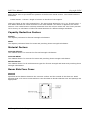
2.2 Dongle Setup
2.3 Configure RAPT for Shared Network Use
3 File Management
3.1 RAPT Data File Types
3.2 RAPT Frame File
3.3 Column
3.4 Cross-Section
3.5 Profile
3.6 RAPT Design Standards File
3.7 RAPT Materials Data File
4 User Interface
4.1 Start Screen
4.1.1 Start Screen - File Menu
4.1.2 Start Screen - View Menu
4.1.3 Start Screen - Help Menu
4.2 User Preferences
4.2.1 Unit and Fonts
4.2.2 User Options
4.2.3 Page Options
4.2.4 Line Options
4.2.5 Output Report Settings
4.3 Keyboard Map
4.4 Data Entry
4.4.1 Cell Data Types
4.4.2 Cell Editing and Navigation
4.4.3 Cell Selection
4.4.4 Cell Repeating
4.4.5 Imperial Length
4.4.6 Cell Formula Input
4.4.7 Cell Colours
4.5 Screen Layout
4.5.1 General Screen Layout Principles
Table of Contents
1
RAPT User Manual
4.5.2 General Toolbar Layout
Copyright PCDC
4.5.3 General Menu
4.5.3.1 General File Menu
4.5.3.2 General Edit Menu
4.5.3.3 General View Menu
4.5.3.4 General Tools Menu
4.5.3.5 General Report Menu
4.5.3.6 General Window Menu
4.5.3.7 General Help Menu
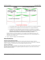
4.5.4 General Message Window
5 Design Standards
5.1 Introduction
5.2 General
5.3 Prestress
5.4 Reinforcement
5.4.1 Limits
5.4.2 Arrangement
5.5 Design
5.6 Deflections
5.7 Load Combinations
6 Materials
6.1 Introduction
6.2 Defaults
6.2.1 General
6.2.2 Reinforcement
6.3 Concrete Properties
6.4 Reinforcement Bar
6.5 Reinforcement Mesh
6.6 Carbon Fibre
6.7 Structural Decking Types
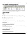
6.7.1 Structural Decking Sheet Properties
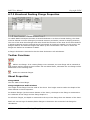
6.7.2 Structural Decking Flange Properties
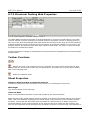
6.7.3 Structural Decking Web Properties
6.7.4 Structural Decking Voids
6.8 Prestressing Strand
6.8.1 Bonded Monostrand Anchorage Sizes
Table of Contents
2
RAPT User Manual
6.8.1.1 Anchorage Properties
Copyright PCDC
6.8.1.2 Tendon Data
6.8.2 Bonded Multistrand Anchorage Sizes
6.8.2.1 Anchorage Properties
6.8.2.2 Tendon Data
6.8.3 Unbonded Monostrand
6.8.4 Unbonded Multistrand Anchorage Sizes
6.8.4.1 Tendon Data
6.8.5 Pretensioned
6.9 Prestressing Bar
6.10 Prestressing Wire
6.10.1 Bonded Multiwire Anchorage Sizes
6.10.1.1 Anchorage Properties
6.10.1.2 Tendon Data
6.10.2 Pretensioned
7 Frame Definition and Design
7.1 Modelling Approach
7.1.1 Tendon Profiles
7.1.2 Tendon Actions
7.1.3 Transverse Beams / Drop Panels / Steps
7.1.4 Concrete Layers / Elements
7.1.5 Frame Systems
7.2 Frame Definition
7.2.1 Input Dialog
7.2.2 General Screen
7.2.3 Frame Shape Screen Layout
7.2.3.1 Span Data
7.2.3.2 Column Data
7.2.3.3 Beam Data
7.2.3.4 Drop Panel Data
7.2.3.5 Transverse Beams/Bands
7.2.3.6 Layers
7.2.3.7 Steps
7.2.3.7.1 Vertical Steps / Tapers
7.2.3.7.2 Horizontal Steps / Tapers
7.2.3.8 Elements
Table of Contents
3
RAPT User Manual
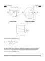
7.2.3.8.1 Trapezoidal
Copyright PCDC
7.2.3.8.2 Circular
7.2.4 Loads
7.2.4.1 Load Cases
7.2.4.1.1 Applied Loads
7.2.4.1.1.1 Line Loads
7.2.4.1.1.2 Panel Loads
7.2.4.1.1.3 Area Loads
7.2.4.1.1.4 Point Loads
7.2.4.1.1.5 Point Moments
7.2.4.1.2 Moment Diagrams
7.2.4.1.2.1 Bending Moment Diagram - Columns
7.2.4.1.2.2 Bending Moment Diagram - Spans
7.2.4.1.3 Moment Envelopes
7.2.4.1.3.1 Bending Moment Envelope - Columns
7.2.4.1.3.2 Bending Moment Envelope - Spans
7.2.4.1.4 Moving Loads
7.2.4.1.4.1 Moving Line Loads
7.2.4.1.4.2 Moving Area Loads
7.2.4.1.4.3 Moving Point Loads
7.2.4.1.4.4 Moving Loads Details
7.2.4.2 Load Combinations
7.2.4.2.1 Load Combinations - Ultimate
7.2.4.2.2 Load Combinations - Short-Term Service
7.2.4.2.3 Load Combinations - Permanent Service
7.2.4.2.4 Load Combinations - Deflection
7.2.4.2.5 Load Combinations - Transfer Prestress
7.2.4.2.6 Load Combinations - Pre-Existing
7.2.4.3 Lateral Distribution Factors
7.2.5 Prestress Data
7.2.5.1 Drape Locations
7.2.5.2 Allowable Profiles
7.2.5.3 Adopted Profiles
7.2.5.4 Details
7.2.5.5 Jacking Sequence
7.2.6 Reinforcement
Table of Contents
4
RAPT User Manual
7.2.6.1 Reinforcing Bar Types
Copyright PCDC
7.2.6.2 Reinforcing Bar Design Details
7.2.6.3 Design Zones
7.2.6.4 User Defined Reinforcement
7.2.6.4.1 Reinforcing Bars, Mesh and Fibre Reinforced Polymers
7.2.6.4.2 Metal Decking
7.2.7 Design Data
7.2.7.1 Ultimate Design Data
7.2.7.2 Crack Control Design Data
7.2.7.3 Deflection Design Data
7.2.7.4 Earthquake Design Data
7.2.7.5 Pattern Load Design Data
7.3 Frame Design/Results
7.3.1 Viewing Output Results
7.3.1.1 Output Tree
7.3.1.2 Viewing Output Results - Graphics Windows
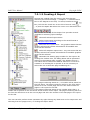
7.3.1.3 Creating A Report
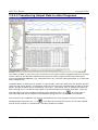
7.3.1.4 Transferring Output Data to other Programs
7.3.2 Input
7.3.2.1 Input Text
7.3.2.2 Frame Graphics
7.3.2.3 Load Graphics
7.3.2.4 Prestress Profiles
7.3.2.4.1 Prestress Profiles
7.3.2.4.2 Graphics
7.3.2.5 Reinforcement Graphics
7.3.3 Warnings
7.3.4 Frame Properties
7.3.5 Prestress
7.3.5.1 Tendon Forces
7.3.5.2 Tendon Actions
7.3.5.3 Secondary Forces
7.3.6 Bending Moments
7.3.6.1 Bending Moments - Column Actions
7.3.6.2 Moment/Shear Diagram
7.3.6.3 Moment/Shear Envelope
Table of Contents
5
RAPT User Manual
7.3.6.4 Bending Moments - Load Cases
Copyright PCDC
7.3.6.5 Bending Moments - Load Combinations
7.3.7 Flexural Design
7.3.7.1 Flexural Design - Reinforcement
7.3.7.2 Flexural Design - Ultimate
7.3.7.2.1 Flexural Design - Ductility
7.3.7.3 Flexural Design - Service
7.3.7.4 Flexural Design - Transfer
7.3.8 Shear Design - Beam
7.3.9 Shear Design - Punching
7.3.10 Deflections
7.3.11 Detailed Reinforcement
7.3.12 Reinforcement Layout
8 Column Definition and Design
9 Cross-section Definition and Design
10 Tendon Profile Definition and Design
T Theory
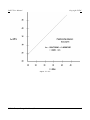
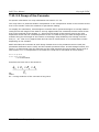
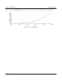
T.1 Preliminary Sizing
T.1.1 Initial Selection of Section Depth
T.1.2 Determination of Load to be Balanced
T.1.3 Selection of Level of Prestress
T.2 Frame Properties
T.2.1 Column Calculations
T.2.1.1 Equivalent Column Calculations
T.2.1.2 Net Column Stiffness
T.2.1.3 Enhanced Column Stiffness
T.2.2 Slab / Beam Calculations
T.3 Blank
T.4 Lateral Distribution Factors
T.4.1 Column Strip Widths
T.5 Critical Sections
T.5.1 Flexure
T.5.2 Shear
T.6 Ultimate Flexure
T.7 Serviceability
T.7.1 General
Table of Contents
6
RAPT User Manual
T.7.2 Cracking Moment
Copyright PCDC
T.7.3 Concrete
T.7.3.1 Stress / Strain Curve
T.7.3.2 Forces in a Cross Section
T.7.3.3 Youngs Modulus of Concrete
T.7.3.4 Creep
T.7.3.5 Shrinkage
T.7.4 Reinforcement
T.7.5 Tendons
T.7.6 Crack Control for Flexure
T.7.6.1 Prestressed Slabs
T.7.6.2 Prestressed Beams
T.7.6.3 Reinforced Slabs
T.7.6.4 Reinforced Beams
T.7.7 Deflections
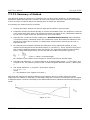
T.7.7.1 Summary of Method
T.7.7.2 Loading Cases
T.7.7.3 Curvature Conditions
T.7.7.4 Deflection Cases
T.7.7.5 Creep Curvature
T.7.7.6 Shrinkage Curvature
T.7.7.7 Tension Stiffening
T.7.7.8 Two Way Systems
T.7.7.9 Deflection Limits
T.8 Transfer
T.9 Ultimate Shear
T.9.1 Punching Shear
T.9.1.1 Punching Shear to AS3600
T.9.1.2 Punching Shear to BS8110 & SABS 0100
T.9.1.3 Punching Shear to ACI318
T.9.1.4 Punching Shear to EUROCODE2
T.9.2 Beam Shear
T.9.2.1 RAPT Summary
T.9.2.2 Principal Tensile Strength
T.9.2.3 Flexure-Shear Strength AS3600
T.9.2.4 Reinforcing for Shear to AS3600
Table of Contents
7
RAPT User Manual
T.9.2.5 Reinforcing for Shear to BS8110 & SABS 0100
Copyright PCDC
T.9.2.6 Reinforcing for Shear to ACI318
T.9.2.7 Reinforcing for Shear - EUROCODE2
T.10 Secondary Moments
T.11 Losses of Prestress
T.11.1 Immediate Losses
T.11.1.1 Friction within the Live Anchorage
T.11.1.2 Friction along the Duct
T.11.1.3 Drawin at the Anchorage
T.11.1.4 Elastic Shortening
T.11.2 Long-term Losses of Prestress
T.11.2.1 Shrinkage of the Concrete
T.11.2.2 Creep of the Concrete
T.11.2.3 Relaxation of the Strands
T.12 Strand Extension
T.13 Columns
T.13.1 Columns - Stocky
T.13.2 Columns - Slender
T.14 Composite Steel Beams
T.14.1 Effective Flange Width
T.14.2 Elastic Section Properties
T.14.3 Design based on Elastic Methods
T.14.4 Design based on Plastic (Strength Limit State) Methods
T.14.5 Shear Stud Design
T.14.6 Stud Detailing
T.14.7 Ductility
T.15 Anchorage Zones
T.16 Prestress Forces Imposed
T.16.1 From Angle Change
T.16.1.1 Forces in Spans
T.16.1.2 Forces in Cantilevers
T.16.1.3 Forces due to Change in Centroids
T.16.2 From Anchorage Eccentricity
T.17 Fibre Reinforced Polymers
T.18 Metal Decking
12 References
Table of Contents
8
RAPT User Manual
13 Appendix
Copyright PCDC
13.1 Local Adaptation of Codes
13.2 Example RAPT Runs
Table of Contents
9
RAPT User Manual
Copyright PCDC
1 Introduction
1.1 Introduction
The RAPT computer package is a design and analysis tool for reinforced and post-tensioned
concrete slab and beam systems, developed by Prestressed Concrete Design Consultants.
RAPT is a computer package for computers running Microsoft Windows Operating System which,
given the basic structural layout of a one or two-way reinforced or partially post-tensioned beam /
slab system, will perform the analysis and design to
1. The Australian Concrete Structures Code AS3600
2. The British Concrete Structures Code BS 8110
3. The American Building Code ACI 318 for Reinforced Concrete
4. Eurocode2
5. South African Concrete Code SABS0100-1
6. Singapore Standard CP 65
7. Hong Kong Code of Practice for Structural Use of Concrete - CP2004
8. Indian Codes of Practice for Reinforced and Prestressed Concrete - IS456/IS1343
These seven base codes can then be further modified to simulate other codes. Users have the
ability to adjust the following parameters
1. Code Specific Design Information
2. Load / Safety Factors
3. Concrete Properties
4. Reinforcement Properties
5. Prestressing Properties
The package has been written by practising structural engineers to be used as an
everyday design tool. The following is a summary of design using RAPT
•
The input is fully interactive using spreadsheet style entries with automatic updating of
graphics. Common parameters are defaulted wherever possible. Interactive Graphic views
of all input information are available for checking values input.
•
The input briefly consists of defining the overall concrete dimensions, applied dead and live
loads, the prestress strand data, tendon start and end locations and loads which the
designer wishes to balance or tendon profiles and number of tendons.
•
RAPT determines the number of tendons required and the profiles they should have to
balance the requested loads. Designers are at liberty to alter any decision that RAPT
makes on their behalf regarding numbers of tendons and tendon profiles. For posttensioned systems RAPT recognises that there are many solutions for a given set of data.
For example more tendons may be added and the drapes modified to achieve the same
balanced loads. In fact, if during a run, the designer wishes to totally revise the
1 Introduction
1
RAPT User Manual
Copyright PCDC
prestressing layout he is free to do so, again and again until a solution is reached that
accomplishes his requirements. In this way the most economical solution may be found.
•
RAPT calculates all short-term and long-term losses of prestress using parabolic or harped
profiles with automatic calculation of reverse curves.
•
Tendon offsets from the concrete soffit to the underside of the ducts are given at
approximately one metre centres. A graphics plot may be requested which draws the
tendon profiles within the concrete cross-section, noting the offsets and spaces thereof.
Strand extension figures are also calculated.
•
An unlimited number of separate tendon profiles may be simultaneously incorporated in
any single design. These may extend full length or stop short at any point within any span.
Tendons may be jacked from either or both ends. For two-way systems separate profiling
is done for column and middle strips. The tendon size, profile, start end locations etc can
vary between column and middle strips.
•
RAPT calculates all forces imposed on the system by the action of the prestress distributed loads, moments, forces at changes in cross-section, eccentric anchorages and
vertical forces at ends of drapes. The forces are calculated at long-term and at transfer
forming two separate load cases that are automatically used in the ANALYSIS option.
•
Secondary reactions and bending moments are automatically calculated by RAPT.
•
Equivalent frame properties are calculated using specific inertias within each span and four
inertias in each column.
•
Loads can be entered as uniform distributed loads, linear distributed loads, point loads,
point moments or as a moment diagram.
•
RAPT will also calculate (if chosen by designer) moments and forces in the structure due to
pattern loading. The pattern loading rules used vary depending on the design code selected
and comply completely with the specific rules for loading pattern and load factors defined
in each design code.
•
RAPT performs a frame analysis for all the loads on the structure and combines them for
transfer, service (moment controlled design envelopes are calculated, ultimate (both
moment controlled and shear controlled design envelopes are calculated) and deflection
cases / conditions using the combinations given in the code selected for the design (or as
modified by the user in input). All the separate load cases or combinations may be plotted
to the screen or printer. The plots and printouts show maximum moments and shears at
the critical sections.
•
For two-way systems the lateral distribution of bending moments across the panel width is
automatically carried out. Again the designer is free to over-ride the factors determined by
the program.
•
The design of each span involves ultimate service, and transfer calculations. These are
carried out at a series of evenly spaced points in each span with specific points included to
cover all possible critical sections. These include critical moment regions, changes in crosssection and ends of internally stressed tendons. (column and middle strip). The locations of
the critical sections for bending at the columns are automatically calculated by RAPT.
Detailed output may be requested giving all steel stresses and concrete stresses. A cracked
section analysis is performed if a section is in tension under working or transfer loads. A
separate stand-alone cross-section utility is included in the package which enables a crosssection of any shape, reinforced/partially prestressed to be fully detailed or investigated for
all of the above and for beam shear.
•
Deflections are calculated using moment-area principles, using curvatures calculated based
on the level of cracking at each of the design points and allowing for tension stiffening and
long term creep and shrinkage effects based on the concrete properties and stresses and
the reinforcement pattern in the member. Transfer (self weight for RC members), short-
1 Introduction
2
RAPT User Manual
Copyright PCDC
term, incremental and long-term deflections are calculated along with span/deflection
ratios for comparison purposes . These may be plotted to the screen or printer if
requested. RAPT also calculates deflections based on odd span and even span patterning of
loads if requested.
•
Punching shear and beam shear are investigated for each column and span. The required
spacing of stirrups is printed for points along each span.
•
Design results may be viewed interactively on the screen for each section of data in tabular
text or graphical format with text information data available interactively. Output reports
are created automatically to the requirements of the designer and may be viewed on the
screen or previewed and printed to any windows printer including file utilities such as
Adobe Acrobat. Each segment of the results may be individually selected. Thus reams of
superfluous output may be controlled.
1 Introduction
3
RAPT User Manual
Copyright PCDC
2 Installation
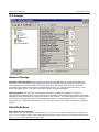
2.1 Program Installation
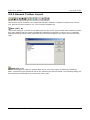
The RAPT installation program is easy to use. Double click the setup.exe program or when
inserting the RAPT installation CD into your CD-ROM drive, the installation program will start.
Step1: The Welcome screen. Click Next button to go to next step.
Step 2: The Licence Agreement screen. Please read carefully. If you don't agree with the licence
agreement, please click Cancel to exit installation. Otherwise, click Next button.
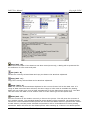
Step 3: Choose the destination folder screen. The default folder to install RAPT is C:\RAPT6. To
specify a different folder, click Browse... button. After the destination folder has been selected,
click Next button to continue.
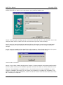
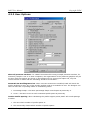
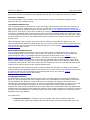
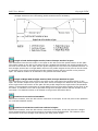
Step 4: Install Dongle driver screen. If you already have an up-to-date dongle driver, choose "Do
not install dongle drivers" option. Otherwise, if you are going to access the dongle locally, choose
"Install dongle drivers" option. If you are going to have a network dongle on this computer and
allow other computers to access this network dongle via network, choose "Setup network dongle
and install network drivers" option. Click Next button to go to next step.
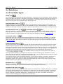
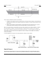
RAPT now has the option of 2 different dongle types
•
Wibu CodeMeter dongles - USB standalone or network dongles.
•
Aladdin Hardlock Dongle - either Parallel Port or USB versions of stand alone or network
dongles.
Drivers for both dongle types can be installed on the same computer if a company has a mix of
dongles. The same version of the RAPT executable will access both dongle types.
2 Installation
1
RAPT User Manual
Copyright PCDC
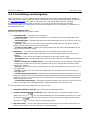
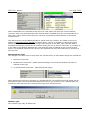
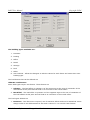
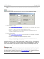
Step 5: Specify code and material screen. In this screen, choose the default design code and
default material you want to use. Also choose your preferred default unit.
Step 6: Select program manager group. This screen will decide where to put the RAPT icon in the
computer start menu. A RAPT short cut icon will also be put onto user's desktop.
Step 7: Now the setup program has gathered all the information it needs to start install RAPT.
Click Next button to start installation or click Back button to go back and change installation
settings.
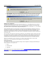
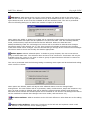
Step 8: Setup is installing all the RAPT files to the computer. This includes the HTML help system.
If your computer already has an up-to-date help system, you will see this dialog
Just click OK to continue.
Step 9: If you chose "Install dongle drivers" option or "Setup network dongle and install network
drivers" option in Step 4, the installation program will start to install one of the Hardlock drivers.
Step 10: The Installation is complete screen. Click Finish button to finish installation. In some
systems, installation will prompt you to restart your computer to complete the installation. You
should close all the other applications, make sure all the current work has been saved, then click
OK to restart your computer.
2 Installation
2
RAPT User Manual
2 Installation
Copyright PCDC
3
RAPT User Manual
Copyright PCDC
2.2 Dongle Setup
RAPT now has the option of 2 different dongle types
•
Wibu CodeMeter dongles - USB standalone or network dongles.
•
Aladdin Hardlock Dongle - either Parallel Port or USB versions of stand alone or network
dongles.
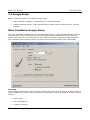
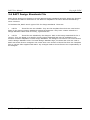
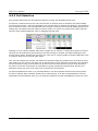
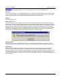
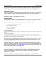
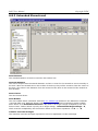
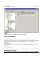
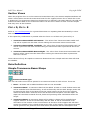
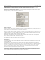
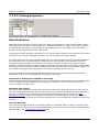
Wibu CodeMeter Dongle Setup
The Wibu CodeMeter dongle does not have proprietary drivers, it uses standard Windows drivers.
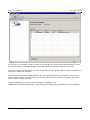
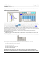
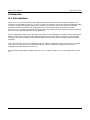
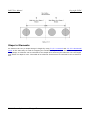
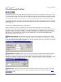
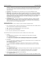
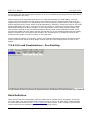
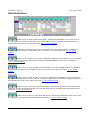
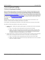
It does however have a comprehensive control program called CodeMeter Control Centre as
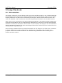
shown below. We have only described the use of the functionality required for RAPT use below.
The CodeMeter Control Centre has its own Help screens that describe all other functionality.
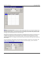
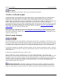
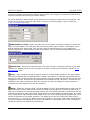
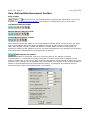
Licensing
The Licensing tab allows the user to create a Context file which must be sent to PCDC to create a
remote update file in cases where the licensing information needs to be updated. Changes can be
made to
•
license type
•
name and address
•
number of licenses
2.2 Installation: Dongle Setup
1
RAPT User Manual
Copyright PCDC
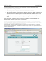
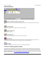
Administration
The WebAdmin button at the bottom of the dialog will take the user to the main administration
pages in your web browser. The following page will be opened on clicking this button.
2.2 Installation: Dongle Setup
2
RAPT User Manual
Copyright PCDC
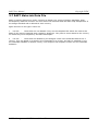
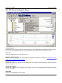
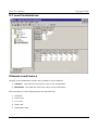
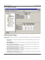
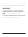
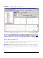
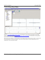
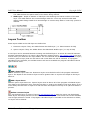
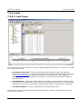
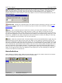
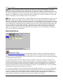
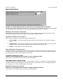
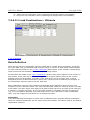
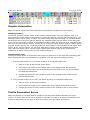
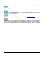
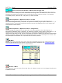
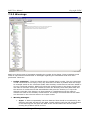
Home Page - Server List
To force CodeMeter to update the list or services available on the computer/network, open the
Home page and click on the Host Name field (shown below). CodeMeter will then search for all of
the services available and list them. This will normally need to be done when the dongle is first
installed on the computer. To view the properties of any service from any of the listed services,
select it here. You will be able to view but not modify the service data on other computers. You
will be able to view and modify the data on the service on your computer. To run to the server on
your computer, select that server here.
2.2 Installation: Dongle Setup
3
RAPT User Manual
Copyright PCDC
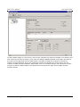
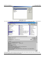
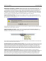
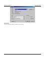
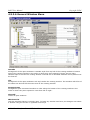
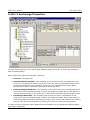
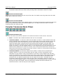
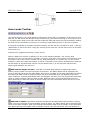
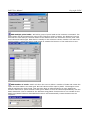
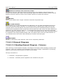
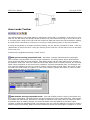
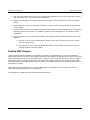
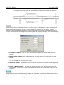
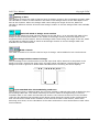
Network Access
The basic network setup is carried out in the Configuration - Network page shown below.
To set up for network access, you need to
1.
2.
On the Dongle Server computer, tick the Run Network Server checkbox.
On the Client computers running RAPT on a different subnet or on a WAN, nominate the IP
address (preferred for different subnet) or the DNS name of the CodeMeter Server in the
Server Search List. Multiple Dongle servers can be nominated. If servers are listed here,
they are the only servers that will be searched for licenses, so if it is necessary to limit
access of certain computers to specific dongles, the dongle server should be nominated
here..
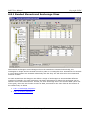
When either of the 2 operations above are carried out, CodeMeter needs to be Stopped and
Restarted in the CodeMeter Control Centre - Process Menu.
You will also need to ensure that the Network Port is open for access in your Firewall program
(done automatically in Windows Firewall) and that both the CodeMeter Executable and the RAPTw
executable are listed in allowed programs in the Firewall.
Where there are multiple CodeMeter dongles on a network, you can list the one/s you want to
access in the Server Search List. CodeMeter will search through the list from top to bottom until it
finds an available dongle.
2.2 Installation: Dongle Setup
4
RAPT User Manual
Copyright PCDC
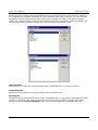
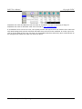
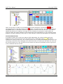
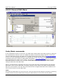
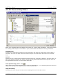
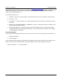
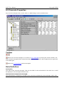
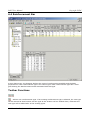
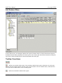
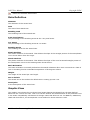
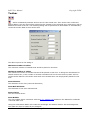
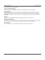
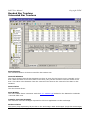
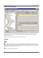
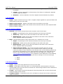
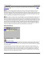
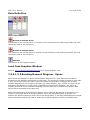
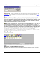
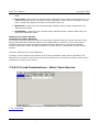
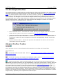
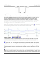
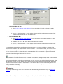
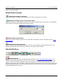
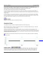
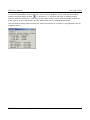
Network Monitoring
To monitor RAPT users logged into a CodeMeter server, select the server name from Home Page Host Name and go to the Server Page shown below.
This lists the dongle information summary including the number of licenses, number used
(shared) and number free. Click on the Details Button for details of the users connected to this
server and you can remove any user from the server from the details page (log them out).
2.2 Installation: Dongle Setup
5
RAPT User Manual
Copyright PCDC
Aladdin Hardlock Dongle Setup
The Hardlock comes in several forms
1
Parallel Port Standalone or Network
2
USB Standalone or Network
3
Internal Standalone or Network (ISA Bus or PCI Slot)
Drivers for all dongle types can be installed as described above when RAPT is being installed. The
driver install programs are also separately available on the CD. The latest drivers available can be
downloaded from our website www.raptsoftware.com. A manual, hlendusersmanual_en.pdf, which
describes the dongle requirements and setup is available on the RAPT CD and in the
\RAPT6\Drivers directory.
If RAPT does not recognise your dongle, first check that it is seated correctly and that it is closest
to the parallel/USB port. Some other parallel port dongles do not allow full data flow on to
following devices and may block some data required by the RAPT dongle.
Network dongle
A network dongle may be installed on any computer on the network. It will normally be installed
on a computer that is always on. The dongle drivers and service should be installed on this
computer. This can be done during the RAPT installation or by running
\RAPT6\drivers\hlsw32.exe. The computer user must have administration rights to install this
program. This will install a service under WinNT/2000/XP or a server program under
Win95/98/ME.
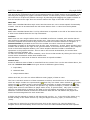
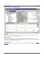
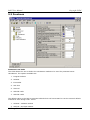
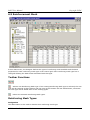
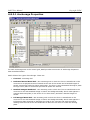
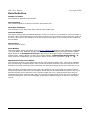
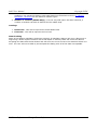
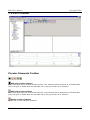
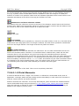
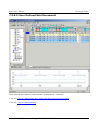
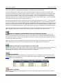
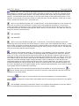
A dongle monitoring program has also been supplied in the drivers sub-directory. The file
supplied, aksmon32.exe, is an installation program for the monitor. Install this program into the
drivers sub-directory.
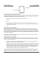
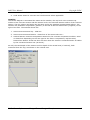
When the aksmon program runs, it will check for the network protocols and attached dongles and
provide a screen similar to the one shown below.
2.2 Installation: Dongle Setup
6
RAPT User Manual
Copyright PCDC
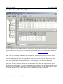
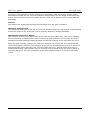
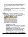
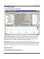
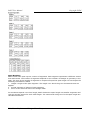
To add a RAPT dongle to the service, click on the computer on which the dongle is to reside in the
tree under the HL-Server branch. Then enter the Module Address 29209 in the space provided in
the view on the right and click the Add button. The table of data will nominate a maximum
number of logins allowed. This is the maximum number the dongle can accept and is not the
number of RAPT licenses available. When RAPT runs on a network dongle, the maximum number
of logins is listed in About RAPT in the Help menu along with the login Access Mode and the
licensee details.
2.2 Installation: Dongle Setup
7
RAPT User Manual
Copyright PCDC
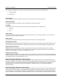
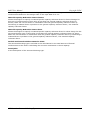
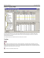
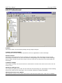
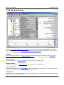
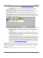
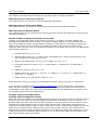
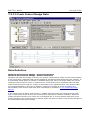
If you click on the dongle number in the tree on the left, the screen above will be shown. It lists
the current logins to the RAPT dongle along with details on the login times for each user.
To logout a user from the dongle, use the delete Entry button at the bottom of this view when the
entry to be deleted is selected.
When a user closes down a RAPT session, the entry will automatically be deleted. If, for some
reason, RAPT crashes, the login entry will remain until the timeout period is finished. This view
can be used to delete the entry.
Further information on use of network dongles is available in the
\RAPT6\drivers\hlendusersmanual_en.pdf manual provided by the manufacturers of the dongles.
2.2 Installation: Dongle Setup
8
RAPT User Manual
Copyright PCDC
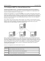
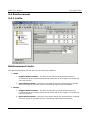
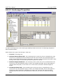
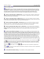
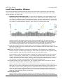
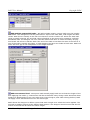
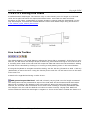
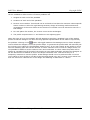
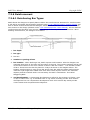
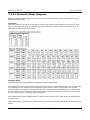
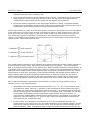
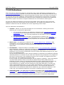
2.3 Configure RAPT for Shared Network Use
This option is available from File -> Config for Network Use menu when no file is opened. It
enables multiple users to use one copy of RAPT in a networked environment while maintaining
their own individual set of configuration files. It means one installation for multiple RAPT users
instead of multiple installations for multiple users.
Despite of this advantage, it is recommended NOT to use it except in cases where users wish to
be able to run RAPT from any computer in the network using their own configuration settings. It is
much more efficient and easy to maintain by installing it onto each individual user's computer in
other cases. For those who have to use single copy of RAPT for multiple users across the network
because of hard disk limitations, network administration policies or just to save the installation
time, here is how it works.
First, multiple users can share a RAPT network dongle. The number of concurrent RAPT users is
limited to the number of allowed users in the network dongle. Or each user can have a standalone
dongle on their own workstation. The following example demonstrates how to set up and
configure RAPT for single installation multi user network use.
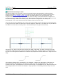
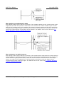
RAPT is installed to the \\AppServer in c:\rapt folder. This folder must be shared and should be
set with read-only permission for normal users. Suppose the shared name is also rapt, then we
can access \\AppServer\rapt from anywhere in the network. Create a network share for user John
at any network station that is connected with \\AppServer. It should be fully accessible by John
and not accessible by other peer users. In this example, we create \\WorkStation1\JohnsRAPT.
We also create similar network share for Mary at \\WorkStation2\MarysRAPT and Peter at
\\WorkStation3\PetersRAPT.
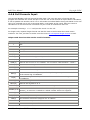
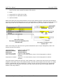
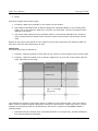
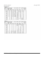
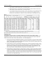
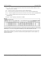
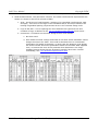
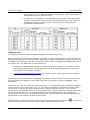
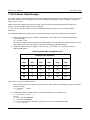
There are 3 configuration files used for RAPT. They are:
File Name
File Description
Default.rnc
Remember each user's name and that user's configuration directory. This is a
text file. (Network users file, Server only)
Default.ruc
Remember the default design code and material, as well as last opened
directory. This is a text file. (User Configuration)
Default.rup
Remember user's preferred unit format, calculation options and output options,
etc. This is a binary file. (User Preferences)
2.3 Installation: Configure RAPT for Shared Network Use
1
RAPT User Manual
Copyright PCDC
The Default.rnc contains the data relating to the users on the network. The .ruc and .rup files are
personal files for each user and a copy of each will be stored in each users private directory space
in the User Preference File Path.
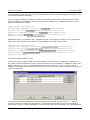
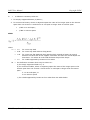
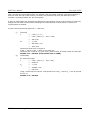
First we need to modify the default.ruc file to reflect the network share path for its path rather
than it's default local computer path. To do this, open default.ruc in \\AppServer\rapt in a text
editor. It should look like this:
[RAPT User Configuration]
Design Code Template Directory=C:\RAPT6\DefaultCodes\
Design Code File=C:\RAPT6\DefaultCodes\Australia.rdc
Materials Template Directory=C:\RAPT6\DefaultMaterials\
Materials File=C:\RAPT6\DefaultMaterials\Australia.rmc
Runtime Directory=C:\RAPT6\Raptrun\
Replace the string "C:\RAPT6" with "\\AppServer\rapt" and delete the content on the right hand
side of the equal symbol in the last line. The modified file should look like this:
[RAPT User Configuration]
Design Code Template Directory=\\APPSERVER\RAPT\DefaultCodes\
Design Code File=\\APPSERVER\RAPT\DefaultCodes\Australia.rdc
Materials Template Directory=\\APPSERVER\RAPT\DefaultMaterials\
MaterialsFile=\\APPSERVER\RAPT\DefaultMaterials\Australia.rmc
Runtime Directory=
Save the modified default.ruc file.
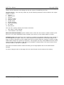
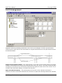
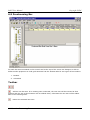
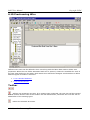
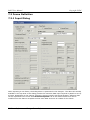
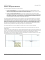
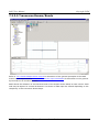
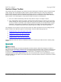
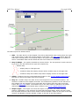
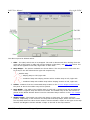
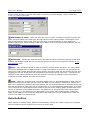
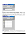
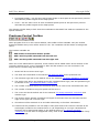
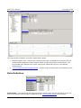
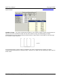
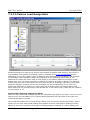
The person who configures RAPT for shared network use can do it on \\AppServer computer or
any other network computer as long as the person has access privilege to \\AppServer\rapt. After
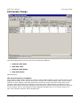
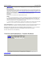
RAPT is started, click File -> Config for Network Use from the menu. Then, in the Config for
Network Use dialog, click the Add button to add an entry and type in the information to get result
a like the following:
You can either type the path name into User Preference File Path or just click the "…" browse
button to specify the path from a dialog box. The network share path must be used instead of
path name such as c:\Users\JohnsRAPT. This is because John may sometimes use \\WorkStation2
2.3 Installation: Configure RAPT for Shared Network Use
2
RAPT User Manual
Copyright PCDC
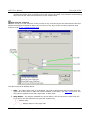
and RAPT won't be able to find the path in c:\Users\JohnsRAPT on \\WorkStation2. This is easiest
done from the Browse Button and selected from the computer and path tree My Network Places.
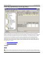
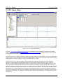
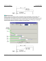
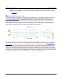
Now RAPT knows where to store John's configuration files. RAPT will prompt for both the
default.ruc and default.rup files to be copied to \\WorkStation1\JohnsRAPT if there are no copies
there already with a dialog like the following
Click Yes button to allow RAPT to copy the default.ruc and then the default.rup file from
\\AppServer\rapt to \\JohnsRAPT. Repeat the same procedure to add Mary's entry and Peter's
entry. To delete entries, click the row headers to highlight the rows to delete and click the
Remove button. The "Change…" button on each row can be used to change the data in the
default.rup file in each users' user preference file path (for example:
\\WorkStation1\JohnsRAPT\default.rup) directory. This will launch the User Preference Dialog and
allow all user preference settings to be changed for that user.
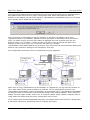
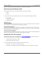
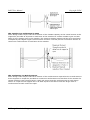
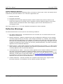
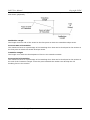
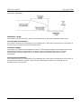
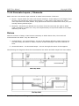
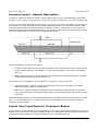
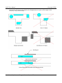
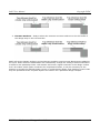
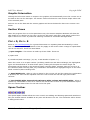
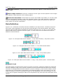
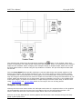
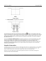
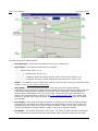
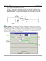
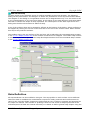
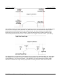
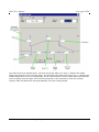
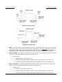
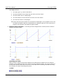
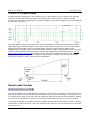
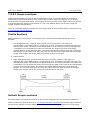
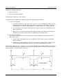
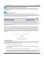
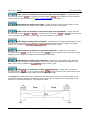
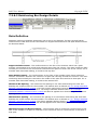
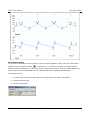
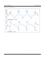
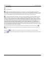
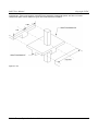
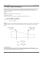
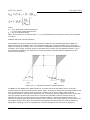
The configuration procedures can be summarized using the diagrams:
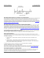
When John is using \\WorkStation2 to access RAPT on \\AppServer, he logs into the network as
John. RAPT looks at the record in Default.rnc and find John's configuration directory is at
\\WorkStation1\JohnsRAPT. It will read Default.ruc and Default.rup in \\WorkStation1\JohnsRAPT
to configure itself for information such as default design code, default material, John's preferred
display unit and output format, colours etc. It means no matter which network computer John is
using, RAPT will always find the correct configuration file for John.
For a network that contains Window98 computers, the shared folder name cannot be longer than
8 characters. Otherwise, Windows98 cannot recognize that share.
2.3 Installation: Configure RAPT for Shared Network Use
3
RAPT User Manual
Copyright PCDC
3 File Management
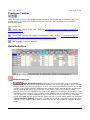
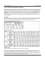
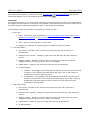
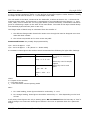
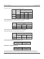
3.1 RAPT Data File Types
Data Files:
File Type
Description
Access
RDC file
RAPT design code file.
Editable in RAPT
RMC file
RAPT material file.
Editable in RAPT
RDS file
RAPT design code template file. Any newly created RDC file is
Not Editable by User
based on one of these RDS files.
RSM file
RAPT material template file. Any newly created RMC file is
based on one of these RSM files.
Not Editable by User
RPF file
RAPT frame file.
Editable in RAPT
Configuration Files:
File Name
Description
Default.rnc
Network Configuration file. Lists each user's name and that user's configuration
directory. This is a text file.
Default.ruc
User Configuration File. It specifies where the template RDS and RMS files are,
which RDC and RMC file should be used as default file, and the last accessed
directory. This is a text file.
Default.rup
User Preference file. Saves a user's preferred unit format, calculation options,
output options, etc. This is a binary file.
3 File Management
1
RAPT User Manual
Copyright PCDC
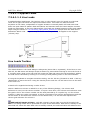
3.2 RAPT Frame File
The RAPT Frame file, .rpf, is a binary file which contains
1. The input data for a RAPT frame run
2. The output results data (optional)
3. A copy of the Design Code Data for the selected design code
4. A copy of the Materials Data for the selected country materials data
5. A copy of the output tree selections.
This file is only editable and the results can only be viewed/printed from RAPT.
3.2 File Management: RAPT Frame File
1
RAPT User Manual
Copyright PCDC
3.3 Column
This section is not available yet.
3.3 File Management: Column
1
RAPT User Manual
Copyright PCDC
3.4 Cross-Section
This section is not available yet.
3.4 File Management: Cross-Section
1
RAPT User Manual
Copyright PCDC
3.5 Profile
This section is not available yet.
3.5 File Management: Profile
1
RAPT User Manual
Copyright PCDC
3.6 RAPT Design Standards File
RAPT allows designers to design to several national design standards and also allows the designer
to customise the data in these files to suit different adaptations of these national standards by
other countries.
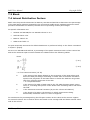
To facilitate this, RAPT uses 2 types of file for design standards. These are
1 .rds file - These files are not editable. They are the template files which are used as the
basis of new Country Design Standards created by designers. They have a name related to a
Design Standard rather than a country, eg ACI318.rds.
2 .rdc file - These files are editable by the designer. Each is the Design Standard file for a
country. They are based on a specific country Design Standard and may be modified to suit
another countries adaptation of that design Standard. The designer has control over some factors
used in Design Standard rules. The basic Design Standard logic, formulae and rules are used in
RAPT with these factors. Designers can create their own versions of these files from the Template
files or edit the files supplied with RAPT. Any changes made to these files are the responsibility of
the designer.
3.6 File Management: RAPT Design Standards File
1
RAPT User Manual
Copyright PCDC
3.7 RAPT Materials Data File
RAPT is used by designers in many countries to design to a variety of design standards, often
developed by different countries. For this reason the materials data has been kept independent of
the design standard and is defined for each country.
Again there are 2 file types. These are
1 .rsm file - These files are not editable. They are the template files which are used as the
basis of new Country Material Sets created by designers. They have a name related to the country
for which they were compiled by the RAPT developers .
2 .rmc file - These files are editable by the designer. Each is the materials Data file for a
country. They are based on a specific set of materials for a country and may be modified to suit
the materials available in another country. The designer has complete control over the materials
definition.
3.7 File Management: RAPT Materials Data File
1
RAPT User Manual
Copyright PCDC
4 User Interface
4.1 Start Screen
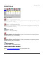
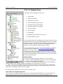
4.1.1 Start Screen - File Menu
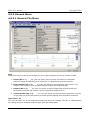
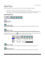
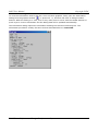
New (Ctrl + N)
Allows the user to create a new design file. Four types of design file can be created in RAPT
1. Frame - The user can define a 2D concrete sub-frame for automatic analysis, design
and detailing as a reinforced or a prestressed concrete member.
2. Cross-Section - The user can define a single complex cross-section of a member with
reinforcement and prestressing tendons for detailed design.
3. Column - The user can define a column shape with reinforcement and prestressing
tendons and produce various interaction diagrams for it.
4. Tendon Profile - The user can define a prestress tendon geometry in terms of high and
low points and produce a tendon profile drawing with calculated extensions
button from the toolbar, a dialog box will be prompted to ask which type
If the user clicks the
of the RAPT file you want to create.
4 User Interface
1
RAPT User Manual
Copyright PCDC
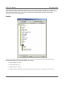
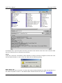
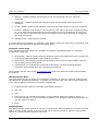
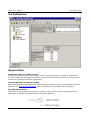
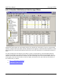
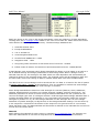
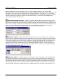
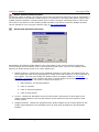
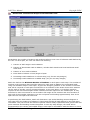
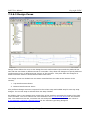
Open (Ctrl + O)
The user can open one of the design files mentioned above or a Design Code file or a Materials file
for editing using the standard windows style open file dialog below..
For Design files, a preview pane has been provided at the bottom which lists some relevant data
from the selected file to help with file selection.
4 User Interface
2
RAPT User Manual
Copyright PCDC
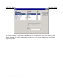
New Defaults
Allows the user to create personalized Design Code and Materials files. These files are based on
the Template files supplied with RAPT for various Design codes and Countries. The user selects a
default file from the dialogs below and is then able to modify the data to suit his own design
needs. Any changes made to Design Code factors should be in accordance with local design rules
and the logic of the formulas in which they will be used for that design code.
Open Defaults
Allows the user to open an existing Design Code or Materials file for viewing or editing.
Delete Defaults
Allows the user to delete an existing Design Code or Materials file.
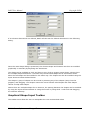
Set Defaults
Allows the user to select which Design Code or Materials file is to be used as the default file when
creating a new design file. Simply select the desired file from the dialog (Design Code shown
below) and press the Set As Default button. The current default file is indicated by a tick.
4 User Interface
3
RAPT User Manual
Copyright PCDC
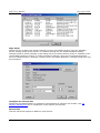
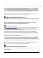
Page Setup
Allows the user to define the printer settings for the current RAPT session using the standard
printer settings dialog shown below. The default settings are the default Windows settings.
Changes made to printer settings in this dialog will be lost when another printer is selected or the
current RAPT session is closed. To make permanent changes, right click on the desired printer
from the Windows Start->Settings->Printers menu and select Properties. Changes made there will
be permanent.
Configure for network use
Allows the user/administrator to update the configuration for network use of RAPT. See 2.3
Network Management for an explanation of the options and process.
Recent Files
Lists the last 9 files opened in RAPT for quick access.
4 User Interface
4
RAPT User Manual
Copyright PCDC
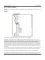
4.1.2 Start Screen - View Menu
Status Bar
Allows the user to select to have the status bar visible or hidden. Clicking with the left mouse
button will toggle between visible and hidden.
Hide/Show Tree
This item is only shown when a Control Tree is available. It allows user to hide the program
control tree. For computers with small or low resolution screens, this allows the data views to use
the full screen width while being viewed/edited.
User Preference
Allows the user to control a set of preferences for units, fonts and data formatting. See 4.2 User
Preferences.
4.1.2 User Interface: Start Screen - View Menu
1
RAPT User Manual
Copyright PCDC
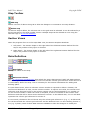
4.1.3 Start Screen - Help Menu
RAPT uses a standard Microsoft HTML Help system for viewing help information, If the files needed
for viewing HTML Help are not loaded on your system RAPT will load them during installation.
Contents (F1)
Pressing F1 or selecting Contents from the Help Menu will open the Help Viewer at the Table of
Contents. The user can then select the area of help to be viewed from the lists in the contents
tree.
Search
Allows the user to search the complete help document for a keyword, phrase or group of works. A
list of the topics containing the search request will be presented and the search request text will
be highlighted wherever it occurs within each topic.
Item Specific Help (Ctrl + H)
When a data cell that has specific help is in focus, pressing Ctrl + H or selecting this item from the
Help menu will open the Help document at the relevant item.
Help About Help
Selecting this item will give a help screen detailing the use of the Help viewer.
Email PCDC Pty Ltd
Automatically launches your computers default Email program with an email to PCDC support.
PCDC Website
Connect automatically to the PCDC website.
About RAPT
Opens a dialog which lists
1. RAPT Version number and copyright.
2. RAPT Licensee details and dongle number
3. Number of users logged onto a network dongle and maximum number of users allowed.
4. Current Usage for demonstration and usage licenses.
4.1.3 User Interface: Start Screen - Help Menu
1
RAPT User Manual
Copyright PCDC
4.2 User Preferences
RAPT users can configure a series of options used by RAPT in the input and display of data and
results. These can be accessed and modified through View->User Preference menu. This menu will
bring up a dialog which allows the user to configure
•
4.2.1 Units and Fonts - The user can select the base unit type to show in all data and
graphics views and to set the format to be used in showing each if the individual unit types
as well as the font characteristics to be used in displaying the information.
•
4.2.2 User Options - The user can select various options used in controlling the data and
report screens
•
4.2.3 Page Options - The user can configure the gape layout for output reports.
•
4.2.4 Line Options - The user can modify the default line colour and styles set in RAPT.
•
4.2.5 Output Report Settings - The user can select the sections of the Output Tree and
Output Report that will be open by default for any new data file.
4.2 User Interface: User Preferences
1
RAPT User Manual
Copyright PCDC
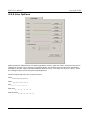
4.2.1 Unit and Fonts
The Unit and Fonts tab in User Preference dialog allows user to change their unit settings and font
settings.
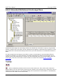
Units
RAPT supports 3 standard unit formats, SI unit, metric unit and imperial.
In addition, it also allows the user to define a personalised format. To do this, the user must
select a base format from one of the standard formats. In every data grid, for each column/row of
data that has a unit type the user can then select a unit type from the list for that data type. To
access the list of unit types, click the right mouse button on the unit type data cell for that
column/row of data. A list of unit types will be offered and the user can select any of those types
for that column/row of data. Once all of the columns have been set as desired the unit format can
be saved using the Tools->Save As User-defined Unit Format menu option. This unit format can
then be selected as the default unit format for this user in the View->User Preference->Unit Type
menu item.
For each unit, the user can further define the precisions that they want RAPT to use to display that
unit type. The selected precisions will then be used consistently throughout the whole program.
The precisions available for SI and Metric and Imperial units are from 0 to 5 decimal places.
For Imperial Unit length measurements, fractions of an inch are accepted from 1/2" to 1/16" and
combinations of feet and inches can be input, eg 12' 7 1/2" or 12.625' are both acceptable. The '
4.2.1 User Interface: Unit and Fonts
1
RAPT User Manual
Copyright PCDC
and " symbols must be used where a combination of feet and inches is used, otherwise in "ft-in"
cells, the input will be assumed to be feet and in "in" cells it will be assumed to be inches. In
cases where fractions of an inch have been selected as the precision, the fraction will be rounded
to the lowest denominator, eg if 10/16" is entered, it will be shown as 5/8" once the edit
operation on the cell is completed.
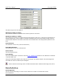
Fonts
The user can also change the following fonts to suit their viewing and printing needs using
standard Windows font selection dialogs (see below).
1. Input header cell font
2. Input data cell font
3. Output font for screen
4. Output font for printing (used when doing a Print Preview or printing to the printer).
4.2.1 User Interface: Unit and Fonts
2
RAPT User Manual
Copyright PCDC
As soon as a change is made to a single data item in the Units/Fonts page, the change will be
made to the currently open RAPT views, allowing the user to see the effects of the change. The
Cancel button at the bottom of the dialog will NOT over-ride changes made in the Units/Fonts
page of this dialog.
4.2.1 User Interface: Unit and Fonts
3
RAPT User Manual
Copyright PCDC
4.2.2 User Options
Show all prestress tendons: For a RAPT frame data file having multiple prestress tendons, for
extremely complex runs or on slow computers, the regeneration of the prestress graphics may be
too slow if all the tendons are shown in the background. By turning this option off, only the
current tendon is drawn and the redrawing would be much faster.
Automatic Re-Profiling Based on: When concrete sections are modified, RAPT will check the
tendon profiling to see if any of the tendon profiles need to be modified to suit. The designer can
select to have the re-profiling based on maintaining either
1. Percentage Drape:- the same percentage drape in each span as previously or
2. Cover:- the same cover at each nominated profile point as previously
Tendon Profile Spacing: When calculating the profile support points, RAPT will round spacings
to either
1. the next whole number of profile spaces or
2. the numerically closest whole number of profile spaces
4.2.2 User Interface: User Options
1
RAPT User Manual
Copyright PCDC
depending on the users selection.
Enable Auto-save every ** minutes: When selected, RAPT will automatically backup the
current data to a temporary file at the selected time interval. This file will be the existing file with
~ at the start of the file extension, eg .~rpf. This file will be stored in the current directory for
saving data files. If the file is closed normally, RAPT will automatically delete the backup file. A
backup file will only exist in a directory if RAPT has crashed this not deleting the file. When RAPT
is started it will automatically open an existing backup file or, if there are more than one backup
files in a directory, will offer the option to select the backup file to be opened.
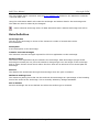
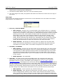
Suppress Warning Dialogs: When the user is about to make a major changes which could
cause the loss of a large amount of data if proceeded with, a warning dialog will come out to ask
for confirmation of the change, eg
If you find such dialog boxes is annoying, turn on this option to suppress warning dialogs and the
changes will be made without warning.
Suppress Graphics Tool tips: Graphic tool tips can provide useful information about the
graphics underneath the mouse cursor in the cross-section views. The same information is also
available on the status bar but not as easy to read.
Turn it off if you don't like the tool tips. The graphic information is still available on the status bar
even if the tool tips have been turned off.
Accept design bar size outside preferred range: When calculating the Detailed Reinforcement
and the Reinforcement Layout from the design areas of reinforcement, RAPT will search within the
range of bar sizes nominated at that location by the designer in the input to try to achieve a
reinforcement spacing within the code and design limits. If you are willing to accept bar sizes
outside this range, select this option. RAPT will check within the nominated range first. If there is
no solution within this bar size range, RAPT will then check all other bar sizes for this bar type.
Suppress error report while editing: Basic Error Checking necessary to ensure that the
graphics can be drawn properly will be conducted every time an input value has been changed. An
error report window will automatically come out to replace the concrete shape graphic view if
there are any errors. If you prefer to see the concrete shape graphics view by default even if
there are errors to report, this option should be turned on. You can then switch to the error
4.2.2 User Interface: User Options
2
RAPT User Manual
Copyright PCDC
window using the
window toolbar button. This will change the setting of this flag in both the
user preferences which are used to control all future RAPT sessions and also the setting for the
current RAPT session which is controlled from 4.5.3.4 General Menu->Tools.
Enable Real-time Scrolling: Real-time scrolling means that, when the user clicks and drags
scroll bars of a view without releasing the mouse, the view changes its current position
continuously giving the user a clear idea where they are. For some slow computer systems, it may
take a long time for a view to respond to the real-time scrolling. Turning this option off means the
view will only change its current position when the user releases the mouse. So turn off this
option if using a slow system.
Circle/Quad Circle Conversion: Allows the user to specify default parameters for the
conversion of circular shapes to a series of trapezoidal shapes. This allows the designer to easily
define multi-sided shapes such as hexagons and octagons and also to reduce circular shapes to
shapes that are more easily manipulated to create partial circular shapes. This will be done
automatically if the designer requests a cut across a circular shape. The parameters required are- Segments in a quadrant of a circle: Number of segments a quadrant circle shape is to be
divided into.
- Segments in a circle: Number of segments a full circle shape is to be divided into.
- Extend Radius: Increase the radius of the circle shape so that the total area of the resulting
trapezoidal shapes is the same as the area of the original circular shape. If this is not selected,
the corners of the trapezoidal shapes will be placed on the original circle shape surface.
- Flat Top: If not selected, the top and bottom shapes will be triangles with a peak point at the
centreline of the circle shape. If selected, the top and bottom shapes will be trapezoids with the
top surface flat and the top points equally spaced either side of the centreline of the circular
shape.
Levels of Undo: Sets the maximum levels of undo that RAPT will allow. Levels of undo can range
between 0 to 20 inclusive. When this value is set to zero, the undo function is disabled. Setting
this value to 5 for example means RAPT will remember the last 5 changes the user makes in a
data file so that they can rollback at most 5 steps. If RAPT is running on a computer that has
limited memory, it is recommended to set Levels of undo to a small value or even zero to
accommodate memory problems. The default setting is 5 levels.
Default Designer: The default designer name will be automatically added to the RAPT frame
data file in the General Data View whenever a new RAPT frame file is created.
The Reset To Defaults button resets the default settings of the User Options tab.
To cancel changes made to this page click the Cancel button at the bottom of the dialog.
4.2.2 User Interface: User Options
3
RAPT User Manual
Copyright PCDC
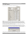
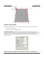
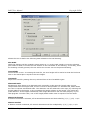
4.2.3 Page Options
Page options tab controls the page layout of a RAPT printed report.
Margins - The left, top, right, bottom margins are the printer margin settings for the page size
selected. Different printers have different minimum print margin settings. The correct print
margins for one printer sometimes are smaller than the minimum margin allowed for another
printer. RAPT allows the user to set the margins between the current printer's minimum allowed
margin and 1/3 of the paper width/height. Tips: The user can set larger margins on left or right if
they need to put punch holes to bind the printed report.
If the values input for the margins by the user violate the printers limits, RAPT will check the
values when this page goes out of focus and post the following warning dialog. The user will be
forced to modify the settings to conform to the printer minimums. The limits shown in the warning
dialog are the mutually exclusive extreme values between which the settings are acceptable.
If RAPT is started with a default printer which has one or more page margin minimums larger than
the settings in User Preferences, the offending settings will be modified to the minimums for that
4.2.3 User Interface: Page Options
1
RAPT User Manual
Copyright PCDC
printer. This check is also carried out when the user attempts to print to a printer. The changed
values will be reflected in this dialog and can be viewed / modified by the user.
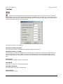
Header/Footer - The user may select any of the following elements to be included in the report
header or footer.
1 version
2 page number
3 licensee
4 license number
5 designer name
6 project name
7 project number
8 frame description
9 file name
10 date & time
The user can specify whether an element should be
1 left, right or centre aligned.
2 in the header or the footer
Show Full Version Number option enables user to show the full version number of RAPT (such
as 6.0.0.2) or just a simplified version number (such as 6.0) in the report header or footer.
Company Logo field allows the user to specify a company logo bitmap (BMP file) to be printed on
the first page of the report. There is no size restriction on the BMP file. If a bitmap image is too
large, it will be reduced to a more usable size (50% of screen width for viewing on screen or page
width inside margins for printing to a printer). The program will only accept BMP file format, other
image formats such as JPEG or GIF will not be accepted. Contact PCDC if you don't know how to
convert a JPEG or GIF file to a BMP file.
The Reset To Defaults button resets the setting of the Page Options tab to the RAPT default
settings.
To cancel changes made to this page click the Cancel button at the bottom of the dialog.
4.2.3 User Interface: Page Options
2
RAPT User Manual
Copyright PCDC
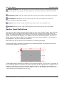
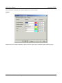
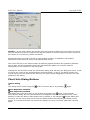
4.2.4 Line Options
RAPT provides 6 defaults lines for drawing graphics output. Each line colour and line style can be
changed to suit the user's viewing or printing needs. The default colours have been selected to
attempt to provide a good contrast between different lines. To change line style or colour, select
the Change button which will open the dialog below.
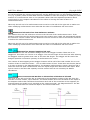
The line styles that user can choose from are
solid:
dash:
dot:
dash dot:
dash dot dot:
4.2.4 User Interface: Line Options
1
RAPT User Manual
Copyright PCDC
The colours for each line can be modified by selecting the Colour button in the Change Dialog
which will present the user with the following colour selection palette from which colours can be
selected. RAPT will not carry out any checks on relative colour difference between lines. This is
completely up to the user.
These six lines will be used in order by RAPT in drawing graphics plots. If only one line is needed
Line 1 will be used, if 2 are needed then Line 1 will be used for the first line and Line 2 for the
second and so on.
Line Thickness
This option allows the designer to control the thickness of the main lines on graphics output to the
printer. RAPT offers four settings from a minimum thickness to a maximum approximately four
times as thick as the minimum. It will not have any effect on viewing a RAPT report on the screen.
Reset To Defaults
The Reset To Defaults button resets the settings of the Line Options tab to the default settings.
This will reset the line colours and styles and the line thickness.
4.2.4 User Interface: Line Options
2
RAPT User Manual
Copyright PCDC
Cancel
To cancel changes made to this page click the Cancel button at the bottom of the dialog.
4.2.4 User Interface: Line Options
3
RAPT User Manual
Copyright PCDC
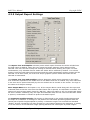
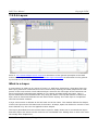
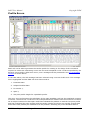
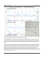
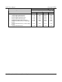
4.2.5 Output Report Settings
The Report Text and Graphics columns preset which report elements should be included into
the final report as default. When the user resets the Report settings, these options will be
selected. The user can then modify the settings if desired before printing the report. In Load
Combinations, only Ultimate Flexure within this folder will be selected by default . For Column
Actions, both the Load Cases Column Actions and the Load Combinations Column Actions will be
selected. In all other cases, all of the text and/or graphics options within that folder will be
selected as nominated.
The Output Tree Text and Graphics columns determine which report elements in the report
tree should be expanded to be visible when a new RAPT frame file is created. Any other elements
in the tree can be opened manually by the user and all can be viewed on the screen. The logic is
the same as for Report settings.
Save Output Data When this option is on, all the output data is saved along with the input and
materials data so that the next time this RAPT frame file is opened, no calculation is needed. This
option will result a larger RAPT frame file (RPF file). When this option is off, the saved RAPT frame
file size is smaller containing only the input and materials data, but the next time this RAPT frame
is opened, recalculation is needed to produce the RAPT Report.
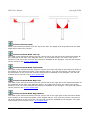
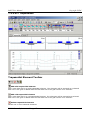
Set Prestress Graphics Density The density is determined by the profile height spacings and
the depth of a character. A setting of 0 will produce the narrowest prestress graphics with the
closest pair of profile heights spaced by exactly 1 character height .This includes the standard
"border" around a character but does not add any extra spaces between the characters. A setting
of 10 will result in a full character height spacing between the closest pair of profile heights.
4.2.5 User Interface: Output Report Settings
1
RAPT User Manual
Copyright PCDC
Intermediate selections will result in that number of 1/10ths of a character height spacing
between the profile heights. This density is used to determine how many rows the tendon profile
must be spread over in the printed output. The final result will normally be a slightly larger
spacing than selected as, for example, 1.5 rows may be needed by calculation from the density,
so 2 rows will be used and the graphics will be evenly spread over the whole 2 rows.
Spans per reinforcement graphics row controls number of spans that will be printed to a
paper width in a reinforcement graphics plot for either the user defined input or Final
Reinforcement Layout in the calculated results . Any remaining spans will be wrapped around and
printed to the next row/s.
Spans per other graphics row controls number of spans that will be printed to a paper width in
graphics other than prestress and reinforcement. Any remaining spans will be wrapped around
and printed to the next row/s.
4.2.5 User Interface: Output Report Settings
2
RAPT User Manual
Copyright PCDC
4.3 Keyboard Map
For users who prefer to use keyboard instead of mouse, RAPT provides keyboard commands to do
most of the operations. Please note that the keyboard commands work only on the window that
has input focus.
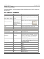
Grid keyboard commands
Command
Keys
Description
Repeat
Ctrl + D
Repeat current cell value. A confirmation box
will popup if the repeat operation is going to
overwrite existing data.
Repeat without confirm
Ctrl + R
Repeat current cell value without user
confirmation.
Show right-click menu
Right-click key or
Show the right-click menu (context menu) in
Context Menu Key
(located close to the
right Ctrl key in a
Windows compatible
a grid. The key looks like this:
keyboard)
Change cell to edit
mode
F2
Change the current grid cell mode to edit and
select the contents of the current cell.
Exit edit mode
Esc
Exit edit mode, retaining previous data
Deselect cells
Esc
Deselect highlighted cells
Rollback error cell
Esc
Undo user input when data error occurs in cell
Move to next cell
Tab / Enter
Accept cell value change and move to the
next available cell.
Highlight cells
Shift + (any) Arrow
Highlight a group of cells
Left Arrow
Accept cell value change and move to the
next cell to the left. In Edit mode, move one
character to left. If at left end of data in cell,
accept cell value change and move to the
next cell to the left.
Move to right
Right Arrow
Accept cell value change and move to the
next cell to the right. In Edit mode, move one
character to right. If at right end of data in
cell, accept cell value change and move to the
next cell to the right.
Move up
Up Arrow
Accept cell value change and move to cell
above.
Move down
Down Arrow
Accept cell value change and move to cell
below.
Move to left most
Home
Accept cell value change and move to the left
most cell
Move to right most
End
Accept cell value change and move to the
right most cell
Move to left
Dropdown dropdown list Space
4.3 User Interface: Keyboard Map
Dropdown the list of current cell in a
dropdown list cell
1
RAPT User Manual
Copyright PCDC
Select next control row
Ctrl + Down Arrow
Select next control row while in child grid
Select previous control
row
Ctrl + Up Arrow
Select previous control row while in child grid
Next View
Ctrl + Page Down
Select the next tree node when the grid view
is in focus and open up the next grid view.
Previous View
Ctrl + Page Up
Select the previous tree node when the grid
view is in focus and open up the previous grid
view.
Output view keyboard commands
Command
Next Checked Output
Item
Previous Checked
Report Item
Keys
Description
If the current view is an individual text or
graphics output view, this command will open
up the view for the next checked output item.
Ctrl + Page Down
If the current view is the report view, this
command will jump to the next output item in
the report view.
Ctrl + Page Up
If the current view is an individual text or
graphics output view, this command will open
up the view for the previous checked output
item.
If the current view is the report view, this
command will jump to the previous output
item in the report view.
Tree keyboard commands
Command
Keys
Description
Gain focus
Ctrl + Tab
Switch focus from grid to tree
Next Node
Down Arrow
Select the next tree node when the tree is in
focus.
Previous Node
Up Arrow
Select the previous tree node when the tree is
in focus.
Expand Sub-tree
Right Arrow
Expand the current node's sub-tree when the
tree is in focus.
Collapse Sub-tree
Left Arrow
Collapse the current node's sub-tree when the
tree is in focus.
Toggle check box
Space
Check/Uncheck a tree node's check box.
Show/Hide tree
Ctrl + T
Show/Hide all the trees.
Graphic view keyboard commands
Command
Keys
Description
Show Next Item
Ctrl + Right Arrow
Move to next item (span)
Show Previous Item
Ctrl + Left Arrow
Move to previous item (span)
4.3 User Interface: Keyboard Map
2
RAPT User Manual
Copyright PCDC
Show Next Point
Shift + Right Arrow
Move to next point
Show Previous Point
Shift + Left Arrow
Move to previous point
Show/Hide Info Dialog
Ctrl + I
Show/Hide information dialog
Toggle Zoom
Ctrl + M
Zoom in/Zoom out of the graphic view
Menu / Toolbar keyboard commands
Command
Keys
Description
New file
Ctrl + N
Create a new RAPT file
Open file
Ctrl + O
Open a RAPT file
Save file
Ctrl + S
Save the current RAPT file
Cut
Ctrl + X
Cut the selected content and put it into
clipboard
Copy
Ctrl + C
Copy the selected content and put it into
clipboard
Paste
Ctrl + V
Paste clipboard content to current window
Undo
Ctrl + Z
Undo the last change
Redo
Ctrl + Y
Redo the last Undo
Print
Ctrl + P
Print current window
Help
F1
Get RAPT online help
Item Specific Help
Ctrl + H
Get specific help on the current item that has
input focus
Create New Frame
Alt + 1
Create new frame file
Create New CrossSection
Alt + 2
Create new cross-section file
Create New Column
Alt + 3
Create new column file
Create New Profile
Alt + 4
Create new profile file
4.3 User Interface: Keyboard Map
3
RAPT User Manual
Copyright PCDC
4.4 Data Entry
4.4.1 Cell Data Types
String ( Aa
)
Any combination of keyboard characters allowed to a maximum of 127 characters. When editing a
string, the editor will place a ' character at the start. This will be removed when the cell returns to
Overtype mode or looses focus. Users should add two ' characters if they want a string to start
with one as the first will be stripped when leaving the cell.
)
Integer Number cells ( #
Integer Numbers are whole numbers. There is no decimal or fraction portion to the number. All
numeric characters can be used. If the user attempts to input a decimal place or a fraction or an
equation in this type of cell it will result in an error that must be corrected before leaving the cell.
or unit name such as
etc.)
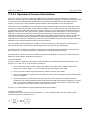
Decimal Number Cells ( #.#
Decimal numbers or Floating numbers have a decimal portion whose viewing length in Overtype
Mode or when out of focus is controlled by the accuracy defined in the user preferences All
numeric characters can be used as well as the formula characters defined in 4.4.6 formulae.
Percentage cells ( %
)
Percentage cells are a special type of decimal number cell which show a maximum of 1 decimal
places (accuracy level 1) when in Overtype Mode or are out of focus and a full decimal number
when in Edit Mode. All numeric characters can be used as well as the formula characters defined
in 4.4.6 formulae.
)
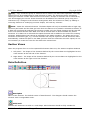
Column Number Cell (#
The column number cell is a special format cell which accepts both the reference column number
and the distance from the column (the data required in the next cell to position the item). This
allows the final position of the item being defined both to be entered in the one cell meaning that
the distance from the column can be made consistent with the column number in one operation if
they both need to change and there is only one set of error checking and also one set of
background calculations based on the modified position of the item. The format of the input is
# ; ## (for example: 2;1000)
The first Integer Number (#) accepts the reference column number and is followed by a semicolon delimiter and then the second Decimal Number (#.#) is the distance from the column to the
point in the same units as the distance from column data.
The minimum input is the first Integer Number for the column number. A distance dimension is
not required. A delimiter must be used if the distance is also to be defined in this cell. If no
distance is defined, the column number will be accepted and used in conjunction with the value
already defined in the distance from column cell.
)
Boolean Cell ( y / n
Boolean cells accept only a Yes/No answer. No characters are allowed to be input. Values can be
changed by clicking with the left mouse button or by pressing the Space Bar.
)
Dropdown List Cell ( List
Drop Down lists give a list of the available options to choose from. In some cases this is a multiple
column list which provides more information on which the user can base his decision. Values can
be changed by clicking left mouse button and choose an item from the dropped list. Values can
also be changed by pressing Space Bar to dropdown the list, then Up or Down Arrow Key to
choose an item and Enter key to accept the chosen item.
4.4 User Interface: Data Entry
1
RAPT User Manual
Copyright PCDC
4.4.2 Cell Editing and Navigation
When the data in a cell is modified, RAPT will check to see whether this modification will affect
other data in this data file and will make modifications as it thinks appropriate these changes will
be 4.4.7 coloured blue in the data to indicate to the user which data has been changed
automatically. If the same value is entered into a cell as was there before the edit was
commenced, RAPT will not accept this as a data modification and no checking or modification of
the data will be done.
String and Numeric Cells
Data cells in RAPT have 2 specific modes
1. Overtype Mode - The whole cell is selected.
- Character Keys - Pressing any character key will delete the previous data and insert
the new character.
- Movement keys - Pressing and Movement keys will simply move focus to the next cell
in that direction.
- Del Key - The Del key will delete the previous data and leave the cell blank. In both
cases, the cell will then be moved to Edit Mode.
- F2 Key or Space Bar - Pressing the F2 key/Space Bar will move into Edit Mode at the
left end of the character string.
2. Edit mode - The cursor is positioned within the character string within the cell.
- Character Keys - Pressing any character key will insert that character at the cursor
position.
- Del Key - The Del key will delete the character to the right of the cursor.
- BackSpace Key - The BackSpace Key will delete the character immediately to the left of
the cursor.
- Shift + Left Arrow or Right Arrow - Text within the string can be selected using Shift
+ Left Arrow or Right Arrow. Pressing character keys will overtype this selection and the
Del key will delete it.
- Esc Key - Pressing the Esc key will undo the current edit operation and move the cell to
Overtype Mode.
- F2 Key - Pressing F2 will accept the modifications to the data and move the cell into
Overtype Mode.
- Horizontal Movement Keys - Pressing Horizontal Movement Keys will move the cursor
along the character string one character at a time. When the end of the character string is
reached, the focus will move to the next cell and place it in Overtype Mode, accepting the
data in the previous cell.
- Vertical Movement Keys - Pressing Vertical Movement Keys will move the focus to the
next cell and place it in Overtype Mode, accepting the data in the previous cell.
To move program focus to a single cell, the user can use
1. Left Mouse Click on the cell. The cell will go into Overtype Mode.
2. Double Left Mouse Click on the cell. If the mouse pointer is within the length of the
, the cell will immediately go into Edit Mode and place the cursor
data in the cell, eg
at that point in the data string. If the mouse click is to the left of the data by more than 1
character, eg
, the cell will go into Overtype Mode.
3. the Arrow keys - move in the arrow direction and wrap around on same row/column of
data at ends of grid. The cell is selected in Overtype Mode.
4.4.2 User Interface: Cell Editing and Navigation
1
RAPT User Manual
Copyright PCDC
4. the Tab key - accept modifications to the data in the current cell and move focus to the
next cell to right and wrap around at right end to first column in next row. The cell is
selected in Overtype Mode.
5. the Enter/Return key - accept modifications to the data in the current cell and move
focus to the next to right and wrap around at right end to first column in next row. The cell
is selected in Overtype Mode.
Note:1 When using the keyboard, the user has to make sure the grid has input focus first before
keystrokes will be effective in that grid. If the grid is not in focus, click the grid window area once
to gain input focus.
2 A range of cell content can be deleted by pressing the Del key after the range has been 4.4.3
selected. Selecting a whole row or column by selecting the header cell and pressing Del won't
delete the whole row or column, nor will it delete the row or column content. Nothing will happen
to the selected data. The user has to use the relevant toolbar buttons or right-click pop-up menus
to delete rows/columns of data that have been added. Sometimes, row/column insertion or
deletion cannot be done until the user specifically selects the row/column (see specific Input
Screen chapters).
Dropdown List Cell
Clicking anywhere in a Dropdown List cell will automatically drop down a list of options for the
user to choose. Clicking again in the currently selected option will leave the cell in focus but
retract the list of options. Pressing the Space Bar or left mouse button when focus is in a
dropdown list cell will drop down the list of options for user to choose.
To select an option, click on the desired option with the left mouse button. This will automatically
select and accept this option. Alternatively, the user can press Up the (or Left) or Down (or Right)
Arrow keys to choose one of the options. Pressing the first character of an option in the list will
move the selection to that option. When the desired option is selected, press Return (enter) to
accept the selection. If the user does not want to change anything, just want to retract the list
that has been dropped down, press Esc key.
If the user only wants to move the current cell to a Dropdown list cell without causing the list to
dropdown, use the keyboard movement keys to move the current cell.
Boolean Cell (Yes/No)
Clicking a Boolean cell will invert the cell value from True to False or from False to True. Pressing
the Space Bar on a Boolean cell will invert the cell value from True to False or from False to
True.
If the user only wants to move the current cell to a Boolean cell without modifying the cell value,
use keyboard movement keys instead of mouse click.
4.4.2 User Interface: Cell Editing and Navigation
2
RAPT User Manual
Copyright PCDC
4.4.3 Cell Selection
Any group of data cells can be selected using the mouse and keyboard quick keys.
To select a continuous area, the user can left click a cell and move to another cell while holding
the left mouse button. Using the keyboard, this can be done by holding the Shift key and pressing
one of the arrow keys. The Cell Selection will not work if the first cell is in Edit Mode (press Esc to
change the cell mode from Edit mode to Select mode). To select non-continuous areas, hold the
Ctrl key while clicking different cells or dragging through cells.
Clicking a row or column header will select a whole row or column. A continuous group of rows or
columns can be selected by left clicking a cell and moving to another cell while holding the left
mouse button down. Holding the Ctrl key to a click row or column header will select different rows
or columns that are not next to each other.
The user can change the current cell within the selected range by pressing one of the arrow keys.
Just make sure the current cell does not go beyond the current selection, otherwise, the selection
will be cancelled. Using a movement key at the end of its row/column forcing a wrap-around to
the other end of the row/column is equivalent to going outside the selected area and the cell
Selection will be lost even if all cells in the row/column are selected.
To select Dropdown list cells, it is recommended to use the keyboard as this will not drop down
the list of options after selection (press Esc to hide the list). It is also recommended to use the
keyboard to select Boolean cells (y/n) as clicking a Boolean cell will immediately inverse its value.
4.4.3 User Interface: Cell Selection
1
RAPT User Manual
Copyright PCDC
4.4.4 Cell Repeating
Users can repeat the current cell value to other cells by using cell the repeating function. This is
invoked by
1. pressing
button in the toolbar
2. clicking Tools->Repeat menu or press Ctrl + D key
3. clicking Tools->Repeat without confirm menu or press Ctrl + R key
4. clicking the right mouse button in the data cell containing the source data to repeat and
select Repeat Cell Data
Repeating can only be done with cells of the same type (for example: Length Cells).
Cell repeating works in different ways depending on the user requirements. These are
No User Selection of Repeat Cells
Without selection of a range of cells, all other cells in the current column of data will be replaced
by the current cell value
1. If a cell that is to be replaced contains a value,
If method 1 (
), 2 (Ctrl + D) or 4 above is used RAPT will ask for confirmation whether
to replace the value in that cell or not (seel below). The user can select to skip the overwrite of data in that cell (Cancel), over-write the data in the cell with the new value (Yes)
or over-write the data in all further cells with the new value (Yes to All).
2. If method 3 above (Ctrl + R) is used, no confirmation will be asked for.
If a cell that is to be replaced does not contain a value (zero), in some special cases in various
input screens a logical copy is performed from associated data already input e.g. column height
below would be set to column height above. See the description in the help for each individual
input screen for the special cases where this applies.
User Selection of Repeat Cells
If a range of cells is 4.4.3 selected by the user for repeating the data from a cell, all of the other
cells in the selected range will be replaced by value in the current cell without a request for
confirmation (same as Ctrl + R) no matter which of the three repeat methods is used. Any noncontiguous group of cells can be selected as long as they are of the same data type as the source
cell. When cells are selected, the source cell is the editable cell.
4.4.4 User Interface: Cell Repeating
1
RAPT User Manual
Copyright PCDC
Dropdown list cells and Boolean cells can also be repeated. The tips of selecting a range of
Dropdown list cells or Booleans cells can be found in 4.4.3 Cell Selection.
If a validation error occurs at a cell, the repeat process will stop at that cell with an Error Coloured
Cell (Red background) and all selected cells after this cell will not be modified. It is then up to the
user to fix the data in the error cell until it is acceptable and then select any other cells that are to
be changed and repeat the data into them as above.
4.4.4 User Interface: Cell Repeating
2
RAPT User Manual
Copyright PCDC
4.4.5 Imperial Length
RAPT is capable of handling imperial length units as either
1 decimal feet
2 feet, inches and fractions of an inch
3 or inches and fractions of an inch.
The imperial length format must follow several rules:
1 Foot Part, defined as a whole number with foot symbol ('), immediately followed by the first
inch character or by a dash (-) or space character as delimiter. Fractions of a foot are not
accepted, decimals may be used but not in conjunction with inches.
2 Inches Part, defined as a whole number representing whole inches (may be omitted if there
are no whole inches in the number), followed by a space character, followed by fraction of an
inch, followed by inch symbol (").
3 If no symbols are defined and the number format is in the form # # #/#, the input will be
assumed to be feet, inches and fractions of an inch.
4 If a fraction is defined, the number before it is assumed to be inches no matter what type of
cell it is in unless feet and inch symbols are provided. Fractions of a foot must be input as a
decimal (if feet only are input) or as inches.
5 If either the foot symbol or the inch symbol is used and there are feet and inches combined,
both must be used.
The foot/inch imperial format can be used in length cells of any unit type. The input string will be
converted to the input type for the data cell. This is shown in the table below.
When converting to fractions of an inch internally, RAPT will always convert the fraction to the
lowest common denominator, so 8/16" will be represented as 1/2" even if the accuracy defined for
the cell is 1/16".
When used in equations, it is always best to include the foot and inch symbols to avoid
misinterpretation of the number.
The following table gives examples of what can or can not be accepted by RAPT.
Input
In feet cell with 1/16"
precision
In inch cell with 1/16"
precision
In millimetre cell with 0.1mm
precision
2
OK, 2 feet
OK, 2 inches
OK, 2 mm
2.3
OK, 2.3 feet
OK, 2.3 inches
OK, 2.3 mm
1 1/2
OK, 1 1/2 inches
OK, 1 1/2 inches
OK, 38.1 mm (which is 1 1/2
inches)
1 1/2"
OK, 1 1/2 inches
OK, 1 1/2 inches
OK, 38.1 mm (which is 1 1/2
inches)
1-1/2"
Wrong, missing foot
symbol
Wrong, missing foot
symbol
Wrong, missing foot symbol
1'-1/2" OK, 1 foot and half inch
OK, 12 and a half inches
OK, 317.5 mm (which is 1'1/2")
1' 1
1/2"
OK, 1'-1 1/2"
OK, 13 inches and a half
OK, 342.9 mm
1 1 1/2 OK, 1'-1 1/2"
OK, 13 inches and a half
OK, 342.9 mm
4.4.5 User Interface: Imperial Length
1
RAPT User Manual
Copyright PCDC
4.4.6 Cell Formula Input
The Decimal Number cells can accept formula input. The user can input a formula and the
program will calculate the result and put it into the cell. If the formula is copied before calculation,
it can be pasted into another cell if it is in edit mode and edited before being calculated in the new
cells. If it is pasted into a cell in Overtype Mode, it will paste as the result. After the result is
calculated in a cell the formula is lost and only the result is retained for that cell.
For example: Entering 1 + 2 * 3 will put the result 7 in the cell.
For length cells, imperial length format can also be used in the formula alone with metric
numbers. The user just have to make sure the correct 4.4.5 imperial length format is used.
Helper math functions that can be used in formula:
Function
(
Description
+
Plus
-
Minus
*
Multiply
/
Divide
)
ABS(X)
Brackets
Returns the absolute (positive) value of X.
ACOS(X)
Returns the arc cosine of X in radians. X is a numeric value between -1 and 1.
ASIN(X)
Returns the arc sine of X in radians. X is a numeric value between -1 and 1.
ATAN(X)
Returns the arc tangent of X in radians.
COS(X)
This function returns the cosine of X in radians.
DEGREES(X) Returns the value in degrees. X: radian value
EXP(X)
LN(X)
LOG(X)
LOG2(X)
Returns e raised to the power specified by the argument, where e is the base
of the natural log 2.71828183.
Returns the log base e of X, where e is the base of the natural log
2.71828183.
Returns the log base 10 of X.
Returns the log base 2 of X.
RADIANS(X) Returns the value in radians where X is the degree value.
ROUND(X, N)
SIN(X)
SQRT(X)
TAN(X)
Returns X rounded to the number of decimal places specified by N (when N is
positive); it returns X rounded to a whole number when N is negative.
This function returns the sine X in radians.
Returns the positive square root of X.
This function returns the tangent of X in radians.
X^Y
Returns X to the power of Y
X**Y
Returns X to the power of Y
4.4.6 User Interface: Cell Formula Input
1
RAPT User Manual
Copyright PCDC
The help function names are not case sensitive.
Examples:
Formula Entered
Result
ROUND(COS(60), 2)
-0.95
DEGREES(ASIN(0.5))
30
sin(radians(30))
0.5
2^3 + log(100) + 16 ** 0.25 12
Formula Restrictions:
1. Formulae do not accept reference cell values. For example, adding cell value from
row1, column2 and row2, column2 together into row3, column 2 is not possible.
2. Formulae are not remembered by each cell. Only the calculated result is remembered.
3. Although the user can use foot-inch format in a formula in any Length cell,
sometimes they cannot be distinguished from the other numbers and operators. It is
recommended not to omit the foot and inch symbols in formulae and to put brackets
around feet-inches values.
4.4.6 User Interface: Cell Formula Input
2
RAPT User Manual
Copyright PCDC
4.4.7 Cell Colours
The grid cells are sometimes given different background colours to indicate their different states.
Data changed automatically by RAPT:
Sometimes editing one cell value or inserting data will cause RAPT to automatically change other
dependant values in other cells in the grid or in other grids. The values changed by RAPT will be
shown in light blue background like this
. Any previous blue marked cells will be shown in a
darker blue background like this
. The corresponding tree node will change to blue as
well. The blue cell colours are to indicate to the user that automatic changes have been made in
the background. Sometimes the calculation of these changes will have required interpretation by
RAPT and the solution it chooses may not be the one preferred by the user. The user should check
all changes made by RAPT to make sure they are acceptable.
To remove the blue colour from a cell (the tree colours will automatically clear when the
associated grids are clear),
1 Modify the data in a cell. This indicates to RAPT that the user has looked at the cell and that
cell colour is cleared.
2 Use the Right mouse button in the coloured cell or select the Clear Cell Colours Toolbar Button
.
Various options will be presented for clearing cell colours in both cases. These are
1. Clear all cells in the current data row.
2. Clear the current cell.
3. Clear all cells in the current grid
4. Clear all cells in all grids.
Remember that these colours have been added to show you what has been changed in the
background in your data. Make sure you check the changes before clearing all of the cell colours.
4.4.7 User Interface: Cell Colours
1
RAPT User Manual
Copyright PCDC
Error value:
. The
When a cell input is invalid, the cell background will be changed to red like this
corresponding tree node will change to red as well. To clear the colour, the user must input an
acceptable value, or press Esc to return to the previous value in the cell. No other cells can be
edited until this error is cleared. This type of error checking is only done in cases where an
incorrect value will cause problems in the background input calculations or in the drawing of the
graphics. All other checking is only done on user request or when the calculations are requested.
Current Control Row:
In situations where two views have parent-child relationship, the content of the child view
depends on the current control row of the parent view. A high-light colour
is used to
indicate the current control row. The current control row in a grid automatically moves to the row
containing a selected cell so changing rows with the mouse or arrow keys will make the new row
the current control row. The only time a new control row will not be selected is when a group of
rows is selected with the mouse.
4.4.7 User Interface: Cell Colours
2
RAPT User Manual
Copyright PCDC
In the above case, Prestress row number 3 (with row header 2 C) in the top data grid is the
control row for Drape Locations in the centre grid: so the drape locations data shown is for tendon
2 column strip (row 3). Drape Locations row number 2 is the control row for prestress graphics so
the coloured span in the graphics is for span 2 (row 2) of tendon 2 column strip.
4.4.7 User Interface: Cell Colours
3
RAPT User Manual
Copyright PCDC
4.5 Screen Layout
4.5.1 General Screen Layout Principles
We will use the Load Cases screen to give an overview of the general screen layout principles
used in RAPT. Most of the concepts used are standard Windows interface concepts and we will not
go into detailed explanation on how these work.
The overall RAPT screen is divided into several windows with different functionality as explained
below. The size and shape of the various windows can be adjusted by moving the mouse cursor
over the boundary between two windows until the cursor changes to one of the following
symbols
. Then depress the left mouse button and drag the window border in the
direction of the arrows in the cursor to the location desired on the screen. In some cases e.g.
frame shape graphics with section views, the section view windows will automatically adjust in
size when the frame shape window is adjusted.
4.5 User Interface: Screen Layout
1
RAPT User Manual
Copyright PCDC
A window with a gripper at one edge can be moved to different positions on the screen to suit the
user and can be undocked from the current position either by double clicking on the gripper or by
selecting and dragging the gripper to another location. Double clicking on an undocked window
will re-dock it in its previous position. Moving it by selecting and dragging the gripper will also redock the window at an edge when the mouse reaches the edge of the RAPT screen space.
Menu Bar
RAPT uses a standard Windows style menu bar that users can use to access specific functionality
of RAPT. This can be accessed with the left mouse button of Alt + Letter from the keyboard.
Status Bar
RAPT uses a standard Status bar. Tool Tip information is repeated on the left of the status bar and
is often more detailed that the Tool Tip information.
Toolbars
RAPT does not use a single toolbar which is available at all times. Instead, each window has it's
own toolbar for operations within that window only. This saves users from the situation of having
enormous toolbars which waste a large amount of screen area and are difficult to navigate. A
General Toolbar is provided at the left of the toolbar row which controls the standard
functionality common to all windows such as edit, view, printing etc. As well, where needed, extra
toolbars will be added to the right of the general toolbar. In the case shown above, with computer
focus in the Frame Graphics Window, the Frame Graphics Window Toolbar is available for
operations in the graphics window. If focus was in the Control Grid Window, the Control Grid
Toolbar would be available, etc.
To make the toolbar for a window available, move focus to that window by clicking the left or right
mouse button somewhere within that window area.
See discussion on each area of data for information on specific toolbars.
Control Tree
Access to different areas of data is controlled from the Control Tree. In the case shown above, the
tree has 3 Control Tree Tabs which give access to different types of data,
1. Input data,
2. Materials data
3. Output Results data.
Within each Tab, the user can select different areas (pages) of data to view.
The Tree is a branch structure of data contained in Folders, Sub-Folders etc to the bottom level
which are Pages. Folders are represented by when they are closed. When clicked on, they open,
shown thus , to admit access to Sub-Folders and eventually to Pages represented by which
simply contain data (or may perform an operation e.g. Report in Output). A folder normally will
simply allow access to sub-folders or pages within it but, in special cases, may open a window
with it's own data which is related to the data in the Sub-Folders and pages it contains, e.g.
Materials->Prestress Strand contains the strand size data and the sub-folders and pages have
tendon and anchorage data for each strand size.
A folder may be opened or closed by left mouse click on the + or - to the left of the folder or by
double clicking on the folder name or by using the Right Arrow key (open) or Left Arrow key
(close).
A page may be opened by a single left mouse click on the name or by using the Enter key.
Program focus will immediately move from the Tree to the Data Window that has been opened.
4.5 User Interface: Screen Layout
2
RAPT User Manual
Copyright PCDC
The tree can be traversed using the Up Arrow, Down Arrow, Page Up and Page Down keys. Also,
the first character of a Folder or Page name can be used. Pressing the same character a second
time will move to the next instance of that character starting a name.
If program focus is in a Data or Graphics Window, Ctrl + Tab can be used to move focus to the
tree where the normal key strokes can then be used to move to and select a new page of data to
view.
Data Windows
Data is presented in Grids which are in separate windows on the screen.
In the simplest form, a tree page will open one data window with a single grid of data in it. In this
form there is only one set of the data, e.g. 7.2.3.1 Spans Data where there is a single grid of data
for all of the spans in the frame.
As the data becomes more complex, there is often a requirement for multiple sets of the same
type of data which cannot be placed in a single grid of data. The Load Cases Data shown above is
a good example of this. For each load case, the user can define the loading in different ways e.g.
as a series of applied loads or as a set of bending moment and shear diagrams. Also, for each
load case defined as a series of applied loads, different types of loads can be defined e.g. line
loads, panel loads, point loads etc.
To handle this type of situation, RAPT has introduced the concept of Control (or Parent) Data
Windows and Child Data Windows. The Control Data nominates the number of instances of
the Child Data that exist and also any general data that applies for that instance of the Child
Data. In the Load Cases data shown above, the Control Data contains a grid of data that provides
an individual row for each load case, Self Weight, Live load etc. This includes data about the load
case including the load case type, load definition type and a description of the load case. For each
row in the control grid (for each load case) there is a set of data defining the loads in that load
case. This data is shown in the Child Data Window. Only one Child Data Window can be viewed at
one time, for the currently selected Load Case in the Control Grid. This Child Window can have as
many loads as the user wishes to define to make up the complete load case.
To change focus to the other window and it's current cell, simply click the left or right mouse
button inside the boundary of the that window. The current cell for editing will immediately
change and the toolbar for that window will replace the previous toolbar.
One row in the Control Grid must always be selected and this is the Control Row. The
background of the Control Row for which the data is being shown in the Child Window is
coloured yellow. Different control rows can be selected using the mouse of the cursor keys when
the control grid is in focus.
Grid Tabs
In cases where multiple data types are associated with a single Control Row, RAPT uses Grid
Tabs to provide several screens of data in the one window. This is shown in the Child Data above
where there are separate sets of data for each load type of applied load, Line Load, Panel Load,
Area Load, Point Load, Point Moment. Select a tab with the mouse to view the data in the grid for
that load type and also to gain access to the toolbar associated with that data. In this case, the
number of applied loads defined in load a type is also printed in the Tab associated with that load
type along with the name.
Current Cell
The current data cell for editing is shown with a dark border. In cases where there are two grids
of data on the screen, as shown above, there will be a current cell in each grid. However, only the
current cell in the window that has focus is immediately editable. This cell will have a double line
4.5 User Interface: Screen Layout
3
RAPT User Manual
Copyright PCDC
thickness border as shown above in the Child grid. This is also a quick way to determine which
window has input focus. To change focus to the other window and it's current cell, simply click the
left mouse button inside the boundary of the that window.
Frame Graphics Window
The Frame Graphics Window displays the data for the data view currently in focus. In the case of
a complex set of data as shown above, it shows the loading diagram for the Current Control Row.
Clicking on a data item in the graphics will highlight that item and also the data that controls that
item. In this case the Current Data Row in the child grid will adjust automatically and if the load
type selected is different to the load type that is already showing, RAPT will change the load type
showing in the Child Grid. The Current Data Row is shown highlighted with a yellow background.
The item selected in the graphics window is shown highlighted with a yellow background in the
case of loads. In other cases where only a line is being shown, e.g. prestress tendons, concrete
reinforcing bars, it is shown as a blue line.
See the discussions on the various data screens for information on what is selectable in each case
and how it will be selected in the data.
Message Window
The Frame Graphics Window also contains the 4.5.4 Message Window which is used to list the
warnings and errors generated during the data check or when calculating the results data.
4.5 User Interface: Screen Layout
4
RAPT User Manual
Copyright PCDC
4.5.2 General Toolbar Layout
This toolbar will be available once a data file has been loaded or initiated. It allows user control
over general functions within a run. The functions available are
New (Ctrl + N)
Allows the designer to launch a new data input for any of the types of data files handled by RAPT.
Any open data file will be closed automatically allowing the designer to save or not if necessary
and the following dialog will be presented from which the designer can choose the new data file
type.
Open (Ctrl + O)
Allows the designer to open an existing data file for any of the types of data files handled by
RAPT. The default type presented will be the same as the last file loaded. The following dialog will
be presented to the designer to choose the file to open.
4.5.2 User Interface: General Toolbar Layout
1
RAPT User Manual
Copyright PCDC
Save (Ctrl + S)
Save the current data. If the data has not been saved previously, a dialog will be presented for
the definition of a file name and path.
Cut (Ctrl + X)
Delete the currently selected data and copy the data to the Windows Clipboard.
Copy (Ctrl + C)
Copy the currently selected data to the Windows Clipboard.
Paste (Ctrl + V)
Paste the contents of the Windows Clipboard to the current focused cell in the Data view. If a
range of data items has been selected, the same range of cells must be available for pasting.
RAPT will not create more rows of data automatically to fit the data being written to it. The data
cells into which the data is to be written must be of the same type as the copied data.
Print (Ctrl + P)
Print the contents of the window currently in focus to the printer. This will print the contents of
any window in RAPT. The standard Windows Printer Dialog will be presented. The default printer
will be the current Windows Default printer the first time this RAPT session is printed from. Within
a RAPT session, the last printer selected and printed to will be remembered for future printing
operations. RAPT will check for the default printer when starting up. If there is no default printer
4.5.2 User Interface: General Toolbar Layout
2
RAPT User Manual
Copyright PCDC
there will be a reasonable delay before RAPT starts up. When printing, if there are no printers
defined on the computer RAPT will present the following message dialog.
Print Preview
Same as Print except that RAPT will print the current window contents to the Windows Print
Preview Window. This can be used for viewing the print format and direct printing to the printer.
Item Specific Help (Ctrl + H)
Will take you to the specific help for the data item selected with the cursor.
Repeat Cell Data
Users can 4.4.4 repeat the current cell value to other cells by using cell the repeating function.
This button also works with the special repeat functions in some data grids where there is a logical
column of data to copy into the current column.
Simple/Detail
In some data screens, the user is offered a choice as to whether a simple shape is to be defined
or a complex one. Two examples are drop panels and transverse beams. This button will only be
available in screens where it can be used.
Clear Cell Status
When RAPT automatically changes data in response to a user modification to associated data, the
data cells modified are coloured blue. This button or the Right Mouse button clicked in a coloured
cell will give you a method of 4.4.7 clearing these coloured cells. Make sure you have checked the
changes before clearing all of the cells.
Check Logic
RAPT checks all data for inconsistencies before calculating results. This button allows the designer
to force a check on the data at any time. Any warning or error messages will be printed in the
4.5.4 Message Window.
Show Message Window
The 4.5.4 Message Window and the 4.5.1 Frame Graphics Window share the same screen space in
the RAPT interface. Use this button to switch between these windows. When the button is
4.5.2 User Interface: General Toolbar Layout
3
RAPT User Manual
Copyright PCDC
expressed, the frame graphics window will be in view. When it is depressed the message window
will be in view. RAPT will automatically switch to the Message Window when
is pressed.
Calculate Results
Will carry out a full data check and calculate the results for the defined data. These can then be
viewed from the Output Tab on the 4.5.1 Control Tree. See the Results section of each data type
to see the results data that is available.
4.5.2 User Interface: General Toolbar Layout
4
RAPT User Manual
Copyright PCDC
4.5.3 General Menu
4.5.3.1 General File Menu
New
Allows the user to create a new design file. Four types of design file can be created in RAPT
1. Frame (Alt + 1) - The user can define a 2D concrete sub-frame for automatic
analysis, design and detailing as a reinforced or a prestressed concrete member.
2. Cross-Section (Alt + 2) - The user can define a single complex cross-section of a
member with reinforcement and prestressing tendons for detailed design.
3. Column (Alt + 3) - The user can define a column shape with reinforcement and
prestressing tendons and produce various interaction diagrams for it.
4. Tendon Profile (Alt + 4) - The user can define a prestress tendon geometry in terms
of high and low points and produce a tendon profile drawing with calculated extensions
Open (Ctrl + O)
The user can open one of the design files mentioned above or a Design Code file or a Materials file
for editing using the standard windows style open file dialog below.
4.5.3 User Interface: General Menu
1
RAPT User Manual
Copyright PCDC
For Design files, a preview pane has been provided at the bottom which lists some relevant data
from the selected file to help with file selection.
Close
Close the current file. If the data, either defined or results, has been changed in the file the user
will be asked whether or not to save the data with the following dialog.
Save (Ctrl + S)
Save the data for the current file. If a file name has not been defined yet, RAPT will prompt for a
file name and path to save to. The default name offered will be the text in the 7.2.2 Frame
4.5.3 User Interface: General Menu
2
RAPT User Manual
Copyright PCDC
Description. If no text is entered here Frame1 will be used, If the name given at this stage already
exists, RAPT will prompt whether or not to proceed and overwrite the existing data.
Save As
Save the current data to a new file and path. The existing file will still exist with the data already
saved to it previously. Any changes that have been made to the file since it was last saved will
only be made in the "save as" file and will not be made in the existing file.
Export
Not implemented yet.
Print (CTRL + P)
Print the contents of the window currently in focus to the printer. This will print the contents of
any window in RAPT. The standard Windows Printer Dialog will be presented. The default printer
will be the current Windows Default printer the first time this RAPT session is printed from. Within
a RAPT session, the last printer selected and printed to will be remembered for future printing
operations. RAPT will check for the default printer when starting up. If there is no default printer
there will be a reasonable delay before RAPT starts up. When printing, if there are no printers
defined on the computer RAPT will present the following message dialog.
Print Preview
Same as Print except that RAPT will print the current window contents to the Windows Print
Preview Window. This can be used for viewing the print format and direct printing to the printer.
Page Setup
Allows the user to define the printer settings for the current RAPT session using the standard
printer settings dialog shown below. The default settings are the default Windows settings.
Changes made to printer settings in this dialog will be lost when another printer is selected or the
current RAPT session is closed. To make permanent changes, right click on the desired printer
from the Windows Start->Settings->Printers menu and select Properties. Changes made there will
be permanent.
4.5.3 User Interface: General Menu
3
RAPT User Manual
Copyright PCDC
Recent Files
Lists the last 9 files opened in RAPT for quick access.
4.5.3 User Interface: General Menu
4
RAPT User Manual
Copyright PCDC
4.5.3.2 General Edit Menu
Undo/Redo commands
If the Undo/Redo function is turned on, the data state existing after each data change is made will
be remembered so that the user can rollback the data to a previous state if desired. If the user
rolls the data back too far, the state can be rolled forward using redo. Refer to 4.2.2 User Options
to turn on or off Undo/Redo function or to change the number of levels of undo available. RAPT
remembers up to the number of data states nominated in 4.2.2 User Options and the data change
that caused each new state to be created. The designer can then use the Undo/Redo functions
described below to revert to any one of the saved data states thus Undoing the effect of data
changes made after that data state.
After a new data state is selected using any of the Undo and Redo functions below, the selected
data state is the current data state. If another change is then made to the data, the data states
after the current state in the list will be lost and the new changed data state will be added to the
end of the list as the current data state.
Undo
Roll Back the Data State one level at a time. This will undo the last change to the data. Continuing
to select Undo will roll the data back through the data states one at a time until the oldest
4.5.3.2 User Interface: General Edit Menu
1
RAPT User Manual
Copyright PCDC
remembered data state that exists is reached. In this menu, RAPT will give descriptions of what
kind of change it is going to Undo in the format of
Undo Screen Name : Data/Action Name.
Undo to ...
Allows the user to roll back to a nominated Data State directly. This will allow the user to Undo
several changes in one step. All of the data changes made from the selected Undo level to the
latest change will be Undone. A dialog box will popup listing all the changes that have been
remembered from the currently selected data state to the first data state remembered as shown
below (all of the items left to undo). The first item in the list is the next available change to be
undone to the earliest remembered change. Click the list item to indicate to which stage the user
wants to roll back the data to. Then click OK button to perform the rollback. The data will roll back
to the data state that existed before the data was changed for the selected Undo Level.
For example, the above dialog indicates that user first changed cell value in Top Reinforcement
Depth from top in General screen, then changed cell value in Bottom Reinforcement from bottom
in General screen, and finally changed left cantilever to left end in Span screen.
Clicking the 2nd item will highlight the first two items. Clicking OK will restore the data state to
the state where the Reinforcement Depth from top has been modified (the data state before the
selected items) and the left cantilever existed and the value for Bottom Reinforcement from
bottom has not been modified.
Redo
Roll Forward the Data State one level. This option will only be available if an Undo operation has
been performed. This will Redo the next change to the data. Continuing to select Redo will roll the
data forward through the data states one at a time until the data state that existed after the last
data change is reached. In this menu, RAPT will give descriptions of what kind of change it is
going to Redo in the format of
Redo Screen Name : Action Name.
Redo to ...
Redo several undo actions that user made in one step. This option will only be available if an Undo
operation has been performed. A dialog box will popup listing all the data states that have been
undone. The first item in the list is the data state for the next change that was made after the
currently selected data state and the last item on the list is the last data change made i.e. in the
reverse order to that shown in the dialog above. Click the list item to indicate which stage you
4.5.3.2 User Interface: General Edit Menu
2
RAPT User Manual
Copyright PCDC
want to roll-forward to. Then click OK button to commit the roll-forward. The current data state
will then be the state after the change nominated in the selected item on the list.
Clipboard commands
Cut (Ctrl + X)
Delete the currently selected data and copy the data to the Windows Clipboard.
Copy (Ctrl + C)
Copy the currently selected data to the Windows Clipboard.
Paste (Ctrl + V)
Paste the contents of the Windows Clipboard to the current focused cell in the Data view. If a
range of data items has been selected, the same range of cells must be available for pasting.
RAPT will not create more rows of data automatically to fit the data being written to it. The data
cells into which the data is to be written must be of the same type as the copied data.
4.5.3.2 User Interface: General Edit Menu
3
RAPT User Manual
Copyright PCDC
4.5.3.3 General View Menu
Status Bar
Allows the user to select to have the status bar visible or hidden. Clicking with the left mouse
button will toggle between visible and hidden.
Hide/Show Tree
This item is only shown when a Control Tree is available. It allows user to hide the program
control tree. For computers with small or low resolution screens, this allows the data views to use
the full screen width while being viewed/edited.
User Preference
Allows the user to control a set of preferences for units, fonts and data formatting. See 4.2 User
Preferences.
4.5.3.3 User Interface: General View Menu
1
RAPT User Manual
Copyright PCDC
4.5.3.4 General Tools Menu
Repeat (Ctrl + D)
Users can 4.4.4 repeat the current cell value to other cells by using cell the repeating function and
asks for confirmation if data already exists in a repeat to cell. This button also works with the
special repeat functions in some data grids where there is a logical column of data to copy into the
current column.
Repeat Without Confirm (Ctrl + R)
Users can 4.4.4 repeat the current cell value to other cells by using cell the repeating function and
automatically overwrites any existing data in the repeat to cells. This button also works with the
special repeat functions in some data grids where there is a logical column of data to copy into the
current column.
Simple/Detail
In some data screens, the user is offered a choice as to whether a simple shape is to be defined
or a complex one. Two examples are drop panels and transverse beams. This button will only be
available in screens where it can be used.
Check Logic
RAPT checks all data for inconsistencies before calculating results. This button allows the designer
4.5.3.4 User Interface: General Tools Menu
1
RAPT User Manual
Copyright PCDC
to force a check on the data at any time. Any warning or error messages will be printed in the
4.5.4 Message Window.
Suppress Error Report
When data errors are detected during background data checks, e.g. prestress profile calculations,
the Message window will automatically replace the Frame Graphics window and show the error
messages. Where multiple data changes are being made this can become annoying. Selecting this
option will stop the Message window from being shown except when the user specifically asks for
a data check or the data calculations are done and errors are found. This option only affects the
current RAPT session. If you want to turn this off permanently for all RAPT sessions, select the
option for suppressing error report in 4.2.2 View->User Preferences->User Options->suppress
error report while editing
Save as User Defined Unit Format
The current unit settings for all data can be saved as a user defined format. This format is then
available to be selected as the default units format in 4.2.1 View-User Preferences-Units and
Fonts.
4.5.3.4 User Interface: General Tools Menu
2
RAPT User Manual
Copyright PCDC
4.5.3.5 General Report Menu
Create Report
Creates an output report using the current settings. If the data has been modified and the results
have not been recalculated, RAPT will automatically recalculate before creating the report.
Clear All
Clears all report settings in the Output Tree..
Reset To Saved Format
Resets all report settings in the Output Tree to the default settings as defined in 4.2.5 View->User
Preferences->Output Report Settings.
Select All Text
Selects ALL text report settings in the Output Tree. Any graphics settings that are already selected
will be maintained.
Select All Graphics
Selects ALL graphics report settings in the Output Tree. Any text settings that are already selected
will be maintained.
Calculate
Forces the recalculation of the results.
4.5.3.5 User Interface: General Report Menu
1
RAPT User Manual
Copyright PCDC
4.5.3.6 General Window Menu
Cascade
Arranges all of the open windows in cascade style from top left of the viewing window to bottom
right of the viewing window in the order in which they were opened. If there are too many
windows open to fit into the viewing window a second set of cascaded windows will be placed over
the first set.
Tile
Arranges all of the open windows in tile style within the viewing window. The windows will all be of
the same size and will fill the entire area of the viewing window.
Arrange Icons
Arranges all open minimized windows in order along the bottom of the viewing window in the
order in which they were opened in rows from left to right..
Close All
Closes all open windows.
Windows List
Lists the windows that are currently open. To bring any window into focus, the designer can select
a window using the mouse or up/down arrow keys.
4.5.3.6 User Interface: General Window Menu
1
RAPT User Manual
Copyright PCDC
4.5.3.7 General Help Menu
RAPT uses a standard Microsoft HTML Help system for viewing help information, If the files needed
for viewing HTML Help are not loaded on your system RAPT will load them during installation.
Contents (F1)
Pressing F1 or selecting Contents from the Help Menu will open the Help Viewer at the Table of
Contents. The user can then select the area of help to be viewed from the lists in the contents
tree.
Search
Allows the user to search the complete help document for a keyword, phrase or group of works. A
list of the topics containing the search request will be presented and the search request text will
be highlighted wherever it occurs within each topic.
)
Item Specific Help (Ctrl + H or
When a data cell that has specific help is in focus, pressing Ctrl + H or selecting this item from the
Help menu will open the Help document at the relevant item.
Help About Help
Selecting this item will give a help screen detailing the use of the Help viewer.
4.5.3.7 User Interface: General Help Menu
1
RAPT User Manual
Copyright PCDC
Email PCDC Pty Ltd
Automatically launches your computers default Email program with an email to PCDC support.
PCDC Website
Connect automatically to the PCDC website.
About RAPT
Opens a dialog which lists
1. RAPT Version number and copyright.
2. RAPT Licensee details and dongle number
3. Number of users logged onto a network dongle and maximum number of users allowed.
4. Current Usage for demonstration and usage licenses.
4.5.3.7 User Interface: General Help Menu
2
RAPT User Manual
Copyright PCDC
4.5.4 General Message Window
When RAPT encounters inconsistencies in the data or experiences errors in calculations which it
can trap, it will list the problems in the message Window. This window will replace the Frame
Graphics Window as shown above. The designer can toggle between these two windows using the
button from the toolbar. The messages may be of five types
1. Warning:- RAPT thinks something looks illogical but it will not interfere with RAPT carrying
out the calculations. Calculation of results is still allowed but the designer should make
sure that he is happy with the data being questioned.
For example, RAPT will warn if the reverse curve radius for prestress tendons is less than
the defined minimum or zero but will allow the calculations to proceed. It is up to the
designer to justify this data. A zero radius is not able to be built so should not be accepted
by the designer. A radius less than the defined minimum but greater than the absolute
minimum bending radius is able to be built but requires special checks on bursting, bearing
stresses and wear of the duct during stressing.
2. Error:- The data is not acceptable and calculation or results cannot be completed. RAPT
will not allow the calculation of the data until this error is resolved.
3. Calculation Error:- There has been an error in the calculation of the results that causes
RAPT to terminate the calculations.
4. Output Warning:- Design Warnings generated during the calculation of the results.
4.5.4 User Interface: General Message Window
1
RAPT User Manual
Copyright PCDC
5. Output Error:- Design Errors generated during the calculation of the results
Relating Messages to Data
The first two message types above are related to the input data. If the designer double clicks on a
data error message, RAPT will open the data window in which the data causing the error is defined
and move data focus to the cell that it thinks is the main cause of the problem.
In the case above, the 5th message has been selected using a mouse double click. The message
line is highlighted and the data cell focus has moved to
1. Prestress Data
2. Adopted Profiles data
3. for tendon 1,
4. span 3,
5. low point profile height for a parabolic profile.
This error occurred because the calculation of the main parabola could not be completed because
the curvature of the main parabola was smaller than the minimum curvature set in Drape
Locations for that span. RAPT has indicated the problem is with the low point profile and has
nominated the span number and the tendon number but there are actually several data items that
could possibly be modified to fix the problem. Selecting any of the Window Tabs to view other
data will also show the span number causing the problem. The other data items that can be
modified to affect tendon curvature problems are
1. Heights at each end of the parabola
2. Locations of each end of the parabola
3. Reverse Curve Radius. This should not be reduced to less than the minimum unless specific
action is taken to allow for high bearing stresses, design of bursting reinforcement and
investigation of the wear effects on the this duct. It should never be reduced to zero for a
final design.
4. For end spans of a tendon, the reverse curve at the anchorages.
button will toggle between the Message View on Frame Graphics View so that
Clicking on the
the designer can also see the graphical representation of the data to help identify the problem.
Often more than one message will apply to the same problem so clearing up one problem may
remove more errors.
4.5.4 User Interface: General Message Window
2
RAPT User Manual
Copyright PCDC
5 Design Standards
5.1 Introduction
The design routines for several design codes have been included in RAPT. A set of default data has
been defined to allow designers to create modified versions of these design codes in which certain
design parameters are able to be controlled by the designer. When these modified versions are
used, the standard code formulae are used with the parameters defined in the modified version.
When a new run is commenced, the design parameters defined in the default Design Standard are
inserted into the data for the run and the Design Standard set in the file in inserted as the Design
Standard on which the calculations will be based. In the run data, the designer can select different
Design Standards if desired. The basic code design data will be inserted into the run data from the
newly selected design Standard.
Several Design Standard files are provided with RAPT and the designer can define more variations
if desired. RAPT also provides a base Design Standard for each design code included in the
program. These are used as the basis of user defined Design Standards when creating a new
design standard variation.
5 Design Standards
1
RAPT User Manual
Copyright PCDC
5.2 General
Code
The design Standard that will be used as the basis for the design. The formulae from this standard
will be used and design checks will be in accordance with this design standard. The current list of
standards is
1. Australia - AS3600
2. USA - ACI318
3. Europe - Eurocode 2
4. United Kingdom - BS8110
5. South Africa - SABS0100
6. Singapore - CP65
7. Hong Kong - CP2004
8. India - IS456/IS1343
Other design standards will be added in time.
5.2 Design Standards: General
1
RAPT User Manual
Copyright PCDC
Country
The country for which the design standard is being set up. Various factors can be modified to suit
the use of a Design Standard in a country other than the one it was written for. This is a text field
and is for the use of the designer only. It is meaningless to RAPT.
Description
A brief description of this version of a design standard. This is a text field and is for the use of the
designer only. It is meaningless to RAPT.
Reinforcement Type
The default design type for new RAPT runs. The options are
1. Reinforced Concrete
2. Bonded Prestress
3. Unbonded Prestress
Member Type
The default member type for new RAPT runs may be defined as
1. Slab
2. Beam
System Type
The default structural system for new RAPT runs. Options are
1. One way - Nominal Width:1. Slab systems:- Designs only a nominal width of the defined slab e.g. a 1000mm
strip of a 8000mm panel of slab as a one way spaning slab. There is no transverse
distribution of moments. Used typically for slabs spanning between beams and slabs
spanning across walls. Self weight and panel loads are calculated for the strip width.
Point loads are applied to the effective (design strip) width. RAPT adjusts the frame
properties to be consistent with the design strip width. Column moments and
reactions are calculated from the design strip results by factoring them by the ratio
of the transverse column spacing to the effective width. No horizontal steps or
tapers are allowed in the side of the slab.
2. Beam Systems:- Will design the effective beam to support the full panel load.
There is no transverse distribution of moments. Self weight and panel loads are
calculated for the strip width. Point loads are applied to the effective beam.
2. One Way - Full Width:1. Slab systems:- Designs the full panel width of the defined slab. The design width
is the panel width at all locations. There is no transverse distribution of moments.
Used typically for slabs spanning between beams and slabs spanning across walls.
Self weight and panel loads are calculated for the full slab width. Point loads are
applied to the full slab width. There is no limitation on the use of steps and tapers
to any surface.
2. Beam Systems:- Not applicable.
3. Two way:- The slab column strips and middle strips. The moments and shears are
distributed to these strips using standard distribution factors defined in most Design
Standards which are further controllable by the designer in 7.2.4.3 Loads->Lateral
5.2 Design Standards: General
2
RAPT User Manual
Copyright PCDC
Distribution Factors. The designer can control the distribution of the effects at the supports
and the maximum span moment points in each span. RAPT uses a parabolic distribution of
the factors between these points to more closely match the distribution in a finite element
analysis. Flexural Design, Reinforcement Layouts and Deflection calculations are provided
for each design strip. Beam Shear calculations are only provided for the column strip.
1. Slab systems:- Can be used for any reinforcement type.
2. Beam Systems:- Only allowed for Reinforced Concrete systems. The effective
beam is apportioned a fraction of the column strip moments and shears in each
span. The effective beam is designed to carry these moments and the middle strip
is designed to carry its share of the moments. Normally it is sufficient to extend the
middle strip reinforcement to the face of the beam to allow the remainder of the
slab in the column strip to carry the left over column strip moment. The designer
should check to see if this will b adequate especially in situations where the portion
of moment assigned to the effective beam is relatively small.
4. Two way - Average:- This is the ACI318 method of designing two way prestressed slabs.
Even though moments and shears are distributed unevenly over the width of a slab panel,
the "average" effect of this is used in the design. The method is not allowed by AS3600
and a modified version is allowed under British Code design rules where stricter limits are
placed on the allowable tension stresses in the concrete in recognition of the effects of
averaging of the moments compared to the real moment concentrations especially at
supports. This method should not be used for partially prestressed slabs.
Braced Frame
Whether or not the frame is braced against sidesway.
Pin-Based Columns
The condition at the base of the columns below the member. Options are
1. Fixed:- columns below are supported from another member of similar type with a moment
connection.
2. Pinned:- Far end of the column below does not have a moment connection e.g. footing.
Column Shortening
RAPT gives the user the option to consider the effects of Column shortening. If Column Shortening
is to be restrained, RAPT places vertical restraints at each column beam node in the Frame
Analysis. Thus no axial shortening can occur. The column shortening can, at times, have a large
effect on moment distribution especially if high loads and columns of varying lengths or axial
stiffness are input into a run. Always be careful when mixing knife edge supports and columns at
different support locations as knife edge supports do not allow vertical movement while columns
do.
Pattern Live Load Factor
The Pattern Load factor is entered as a decimal (fraction of 1). If no Patterning of Live Loads is
required, the user should input 0 and if full Live Load patterning is required, 1 should be input.
The decimal refers to the amount of Live Load used in the pattern combinations i.e. 0.75 indicates
that 75% of the Live Load is used in pattern combinations.
Design Standards define the percentage of load that should be applied for patterning of the live
load. Also, the method used in patterning live loads varies from Standard to Standard. For more
information on patterning of loads for various Design Standards see Theory Section T4.1.
5.2 Design Standards: General
3
RAPT User Manual
Copyright PCDC
Only the load case named Live Load will be patterned. The combination factors used for this case
are used for the envelope of actions created for the patterned live load. RAPT will create two live
load pattern envelopes, one based on the envelope of moments at each design location with coexisting shears and one based on the shear envelope at each point with co-existing moments.
Pattern load cases are not used for deflection calculations. The full live load case is used.
Design Period in years
The time over which the structure is expected to be loaded in years. This figure is defaulted to 30
years as creep and shrinkage effects are minimal after this period. The long term losses are
calculated at this time. The long term and incremental deflections are also calculated at this time.
Estimates of effects at shorter times may be calculated by nominating the time at which
calculations are required e.g. the expected deflection at 6 months can be calculated by
substituting 6 months as the loaded period (.5 years).
Relative Humidity
This dictates the shrinkage and creep characteristics. The drier the air, the greater the tendency
to lose water from the concrete and the greater will be the creep and shrinkage.
To simulate AS3600 Environment Variables, the following values can be used
1. tropical near coastal (65% Humidity)
2. temperate (55% Humidity)
3. interior (50% Humidity)
4. arid (40% Humidity)
Average temperature
The average temperature for the design area. RAPT modifies creep and shrinkage for temperature
affects.
Moment Redistribution
The designer can define a % of moment to be redistributed. RAPT will then redistribute the
ultimate moment envelope and the associated shear envelope for Ultimate strength calculations.
Serviceability load combinations remain unaffected.
Where the Ultimate moment at a design point is of a different sign to the service moment, RAPT
will apply a factored Ultimate Moment of the same sign as the service moment equal to 1.2 x
Mservice to ensure that there is sufficient strength on any face that will be tensile through any of the
loading stages of the member.
If Moment redistribution is requested, RAPT will automatically apply all limitations to the design
for ductility as defined in the different design codes. It will over-ride any user defined setting for
depth of neutral axis limit in the 7.2.7.1 Design Data in doing this unless the defined value is less
than that calculated from the Design Standard rules.
Designers should be aware that the use of large amounts of redistribution of the moments in a
member introduces severe limitations to the ductility requirements of a member due to the
reliance in the strength calculations on increased rotations at plastic hinges and also could
introduce a requirement for extra reinforcement under service load conditions to control crack
widths. The resulting design could be less economical than a design without or with lesser
redistribution of moments.
RAPT does not redistribute moments at end columns. To redistribute moment from an end
column, a user should use the option to modify the Izz of a column in the F3 Columns screen.
5.2 Design Standards: General
4
RAPT User Manual
Copyright PCDC
RAPT will only allow redistribution of moments for 7.2.3.2 Braced Frames. RAPT will limit the %
redistribution defined in the input to the maximum allowed by the relevant design standard. It will
allow both positive (reducing support moments) and negative (increasing support moments)
values of the redistribution %.
The maximum limits are
1. AS3600:- 30% for normal ductility reinforcement and 0% for low ductility reinforcement
2. ACI-318:- 15%
3. Eurocode 2:- 30% for class B or C reinforcement and 20% for class A reinforcement (Low
Ductility).
4. BS8110, CP 65, IS456/IS1343 and SABS0100: 30% for reinforced concrete members and
20% for prestressed members.
5. Hong Kong CP2004: If concrete strength less than 70MPa, 30% for reinforced concrete
members and 20% for prestressed members. If concrete strength is greater than 70MPa,
no redistribution is allowed.
Concrete Strength
This is the concrete strength basis on which the formulae in the code are based. The options are
1. Cylinder Strength.
2. Cube Strength.
If the materials type selected is defined as the opposite type to that required by the design code
RAPT will convert the materials data concrete strengths to the code strength type using
cylinder strength = .8 * cube strength
5.2 Design Standards: General
5
RAPT User Manual
Copyright PCDC
5.3 Prestress
Prestress Loss basis
This field allows the user to define the calculation method to be used for prestress losses
calculations. The options available are
1. Program Default
2. AS3600
3. Eurocode2
4. ACI-209
5. Zia et al
6. CEB-FIP 1970
7. CEB-FIP 1978
The default value in the field is Program Default which will cause RAPT to use the internal default
method for each design code. This is
1. AS3600:- AS3600 method
2. ACI318:- ACI-209 method
5.3 Design Standards: Prestress
1
RAPT User Manual
Copyright PCDC
3. Eurocode2:- Eurocode2 method
4. BS8110:- AS3600 method with adjusted creep and shrinkage values to suit local
conditions
5. SABS0100:- AS3600 method with adjusted creep and shrinkage values to suit local
conditions
6. CP 65:- AS3600 method with adjusted creep and shrinkage values to suit local conditions
7. CP2004:- CEB-FIP 1970 method. The Hong Kong code requires an extra multiplying factor
cs = 4 to allow for shrinkage values in local concretes. This is included only for the Hong
Kong Code and is used no matter which shrinkage/creep model is selected for designs to
the Hong Kong Code.
8. IS456/IS1343:- CEB-FIP 1970 method
A method which is acceptable in a designer's local design community and which is consistent with
the concrete manufactured in that area should be used.
Prestress Tendon Type
Three prestressing types options are available for bonded prestressing and 2 for unbonded
prestressing. These are
1. Monostrand:- Flat duct post-tensioning tendons used in both slabs and beams. Strands are
normally stressed individually rather than as a tendon.
2. Multistrand:- Round duct post-tensioning tendons used mainly in larger beams. Strands
are normally stressed as a group.
3. Pretensioned (not available for unbonded prestressing). Strands stressed between
buttresses and released after the concrete has hardened.
These names are also used in the 6.1 Materials Data where the different tendon sizes available
are defined.
Minimum Rebar Basis
This field allows the user to define the calculation method to be used for minimum reinforcement
calculations for prestressed members. In general the selected code rules will be used unless one
of the options below is selected. The options available are
1. Program default (UBC for unbonded prestressed members)
2. ACI-318
3. UBC
4. TR43 (This is not considered by RAPT to be the default method for BS8110 design or
Eurocode 2 design or for any derivates of BS8110. The designer must select this option if it
is to be used for a design).
5. None
Profile Spacing
The default tendon profile spacing to use for in this member. RAPT will base the number of profile
spaces in each profile section on this value and will round the number of spaces in each profile
section to a whole number based on this value.
5.3 Design Standards: Prestress
2
RAPT User Manual
Copyright PCDC
Drape Tendons to
Allows the designer to include these drape to locations in the default settings for RAPT. RAPT will
drape tendons to column centreline or face of band beam or drop panels by default. If either of
these are selected they will be added to these default drape to locations.
1. Face of Columns if exist
2. Face of Transverse beams if exist
Slabs
Allows the designer to specify values for the following for new slab designs
1. Top Cover to Duct:- cover to the top of the duct from top surface of the concrete member
2. Bottom Cover to Duct - End Spans:- cover to the bottom of the duct from bottom surface
of the concrete member in end spans.
3. Bottom Cover to Duct - Internal Spans:- cover to the bottom of the duct from bottom
surface of the concrete member in internal spans.
4. Reverse Curve radius:- Default Reverse Curve radius to use for all transition curves for all
tendons in the member.
Beams
Allows the designer to specify values for the following for new beam designs
1. Top Cover to Duct:- cover to the top of the duct from top surface of the concrete member
2. Bottom Cover to Duct - End Spans:- cover to the bottom of the duct from bottom surface
of the concrete member in end spans.
3. Bottom Cover to Duct - Internal Spans:- cover to the bottom of the duct from bottom
surface of the concrete member in internal spans.
4. Reverse Curve radius:- Default Reverse Curve radius to use for all transition curves for all
tendons in the member.
5.3 Design Standards: Prestress
3
RAPT User Manual
Copyright PCDC
5.4 Reinforcement
5.4.1 Limits
Reinforcement Limits
The data defined below can be input for the following conditions
1. Slabs
1. Support Reinforcement:- The face of the slab on which Reinforcement is
concentrated at the support and extends either side of the support (normally top
over the column).
2. Span Reinforcement:- The face of the slab where the reinforcement is spread
over the length of the span with the controlling requirement at midspan.
2. Beams
1. Support Reinforcement:- The face of the beam on which Reinforcement is
concentrated at the support and extends either side of the support (normally top
over the column).
2. Span Reinforcement:- The face of the beam where the reinforcement is spread
over the length of the span with the controlling requirement at midspan.
5.4 Design Standards: Reinforcement
1
RAPT User Manual
Copyright PCDC
Data Definition
Reinforcement Cover
The depth to nearest surface of the main reinforcement bar from the relevant concrete face.
Maximum Spacing
The maximum reinforcing bar spacing to use in determining the reinforcing bar size to use and in
detailing the reinforcement on the relevant concrete face.
Minimum Spacing
The minimum reinforcing bar spacing to use in determining the reinforcing bar size to use and in
detailing the reinforcement on the relevant concrete face.
Infill Bars
When detailing reinforcement, normally, the support face reinforcement is not continuous over the
full length of the span. In beams it is often practical to add extra nominal bars to fill this area and
provide supports for shear ties and cross reinforcement. If Yes is selected here, the default
settings in a new run will be set to yes for this option and RAPT will fill in blank areas in the
reinforcing pattern with nominal bars (nominally 12mm bars at 500 centres for slabs and 16mm
bars at 500mm centres for beams).
Stagger Bars
Away from the peak bending moment location in a design zone, the area of reinforcement
required is normally less than is required at the maximum point. It is often more economical to
curtail some of the reinforcing bars at a point within the design zone and only continue half of the
bars to the end. Selecting Yes for this option will tell RAPT to stagger the curtailment point so that
half (rounded down for odd numbers of bars) of the bars are curtailed when they are no longer
needed.
Reinforcement Arrangement
RAPT allows the designer to specify limits on the spacing of reinforcing bars. Two limits are
provided for each of the following
1. Code Maximum spacing between centrelines of bars
1. Overall Limit:- a spacing limit in length units
2. Proportional Limit: a spacing limit based on a factor times the depth of the
concrete.
2. Code Minimum clear spacing
1. Overall Limit:- a clear spacing limit in length units
2. Proportional Limit: a clear spacing limit based on a factor times the bar diameter.
5.4 Design Standards: Reinforcement
2
RAPT User Manual
Copyright PCDC
5.4.2 Arrangement
Separate reinforcing detailing parameters can be set by the designer for both top and bottom
reinforcement. RAPT asks for the information for Support Reinforcement and Span Reinforcement
as described below.
Support Face Reinforcement:- The reinforcement on the face of the member which has a peak
moment concentrated at a column and reducing away from the column. The main reinforcing bars
normally are centred on the column and extend into the spans on either side of the column. For a
member with downward loading, it would be the top face.
Span Face Reinforcement:- The reinforcement on the face of the member which has a
maximum moment somewhere between the columns in a span and reducing towards the columns.
5.4.2 Design Standards: Arrangement
1
RAPT User Manual
Copyright PCDC
The main reinforcing bars normally are centred on the middle of the span and confined to that
span. For a member with downward loading, it would be the bottom face.
Reinforcement Detailing Limits
Default Detailing Limits can be defined separately for two structural types,
1. Slabs
2. Beams
For each structural type the default limits can be set for three alternate design conditions
1. Non-Seismic
2. Moderate Risk Seismic
3. High Risk seismic
Continuous Top
Continuous Bottom
The minimum area of continuous reinforcement in the face of the member in a span as a fraction
of the maximum area of reinforcement in that face in that span.
Bottom into End Supports
The minimum area of span face reinforcement extending into the support at an end support as a
fraction of the maximum area of span face reinforcement in that span. This option is only used at
end columns where no cantilever exists.
Bottom into Internal Supports
The minimum area of span face reinforcement extending into the support at internal supports as a
fraction of the maximum area of span face reinforcement in that span.
Default Bar Cut-off Locations
The default locations for bar cut-off positions for 7.2.6.2 staggered bars as shown below can be
set by the user using for the two conditions below
1. Support Reinforcement bar Cut-offs
2. Span Reinforcement bar Cut-offs
Two cut-off locations are able to be defined for each case. These are
1. Main Bars:- The end of the reinforcing bar type.
2. Short Bars:- The stagger end location if staggering of the ends of the bars is required.
5.4.2 Design Standards: Arrangement
2
RAPT User Manual
Copyright PCDC
5.5 Design
General Design
Capacity reduction factors are used by many Design Standards, eg AS3600 and ACI318, to
account for the variability of the material properties controlling strength and the likelihood of
under-performance of a member. This factor also takes into account inaccuracies in design
procedures and small deficiencies in workmanship on site (i.e. concrete dimensions etc). This
factor should be set to 1 for other code types which use material factors.
Material factors are used by many Design Standards, eg BS8110, SABS0100, CP2004,
IS456/IS1343 and Eurocode2, to account for the variability of the material properties controlling
strength and the likelihood of under-performance of a member. This factor also takes into account
inaccuracies in design procedures and small deficiencies in workmanship on site (i.e. concrete
dimensions etc). This factor should be set to 1 for other code types which use capacity reduction
factors.
Data Definition
Max ratio of Ieff to Igross
RAPT allows the user to specify a maximum Ieffective value. This value is specified as a fraction of
Igross. Ieffective is used by RAPT while calculating deflections. If a section is uncracked, RAPT will set
Ieffective = Igross unless specified in this input.
5.5 Design Standards: Design
1
RAPT User Manual
Copyright PCDC
It is recommended by the authors that Igross is not used by designers for deflection calculations
unless a concrete member is completely unrestrained. The moments applied during the calculation
of Ieffective normally only consider the vertically applied forces. Other forces such as restraint effects
due to temperature, shrinkage and creep are not allowed for in the design moments. To make
allowance for the effect of these additional forces on the cracked and effective inertia's in lightly
loaded members, the authors recommend that designers restrict the Ieffective / Igross ratio to 0.6 0.7.
Minimum Rebar Cut-off
AS3600 BS8110, CP65, SABS0100, CP2004, IS456/ IS1343 and ACI318 state that the minimum
applied ultimate moment, M*, to be designed for is 1.2*Mcr. Eurocode 2 uses 1.15*Mcr.
The codes require designers to include sufficient reinforcement to satisfy a moment which causes
the member to crack. The ultimate strength in bending is calculated assuming a fully cracked
section. For small percentages of steel, this moment could be less then the moment Mcr to cause
cracking. Failure of such a member would be quite sudden. To prevent such a failure, the ultimate
strength in bending must be greater than Mcr.
However there is no concession for the situation when the section's design strength in bending,
*Mu is much greater than the applied ultimate moment, M* (ie ØMu >> M*).
In AS1480 designers were permitted to relax this rule if ØMu was greater than 1.33M* (ie ØMu >
1.33 M*). [Also see ACI318 Clause 10.5.2] This, in effect, gave an extra factor of safety on the
failure condition but did not ensure that cracking occurred prior to failure. Some other codes allow
similar concessions.
RAPT has given the user the option of accepting the code as read by leaving the value for this
parameter as 0 and then minimum M* is taken as defined in each code.
If this rule is to be supplanted with something similar to AS1480 then a number may be entered
in the table. eg. 1.33. This will instruct the program to accept the section as being of adequate
strength, i.e. no need to provide extra reinforcement to satisfy minimum flexural reinforcement
rules, as long as ØMu > 1.33M*. If this is not satisfied then reinforcement is added until ØMu >
1.33M* or Ø1.2Mcr whichever is the lesser. 1.33 is the minimum value allowed by RAPT.
Earthquake Design
The designer can request that earthquake design rules be applied in designing and detailing for
flexure and shear. The options are
1. None
2. Moderate Risk
3. High Risk
Maximum neutral Axis Depth for Ductility
Ductility is an important aspect of the design of a section / member. A ductile member will
undergo large deflections before failing. This acts as a safety measure in that members can be
seen to be dangerous before actually failing. For appropriate code ductility limits without
redistribution of moments, see
1. AS3600 Clause 8.1.3, ku = 0.4
2. ACI318 Clause 18.8.1, ku = 0.428 (when rearranged from a tension strain limit of .004
and a compression strain limit of .003)
5.5 Design Standards: Design
2
RAPT User Manual
Copyright PCDC
3. BS8110 and CP65 Clause 3.2.2.1, 3.4.4.4 and 4.2.3.1 ku = 0.5
4. Eurocode2 Clauses 5.4 and 5.5, ku = 0.448 Grades <= C50/60 ku = 0.368 Grade >
C50/60
5. SABS0100 Clause 4.3.3.4, ku = 0.5
6. CP2004 Clause 6.1.2.4b, ku = .5 for fcu <= 40MPa, ku = .4 for fcu <= 70MPa and ku =
.33 for fcu <= 100MPa
7. IS456 clause 37.1d and IS1343 clause 21.1.1d
RAPT allows the user to over-ride our interpretation of each code if they feel it is warranted.
If the designer nominates that 7.2.2 moment redistribution is to be allowed for in the design,
RAPT use the formulae in each design standard to set a ductility limit based on the amount of
redistribution used. RAPT will never use a limit higher than the one defined here no matter what
the calculated value from the redistribution.
Crack Width Calculations
This field allows a designer to nominate whether or not crack width calculations are to be
performed for a member and allows a user-defined crack width limitation to be defined for designs
to BS8110, SABS0100, CP2004, IS456/ IS1343 and CP 65. If the value is left at DEFAULT, RAPT
will use the default values of
1. Reinforced Concrete members - .3mm
2. Prestressed concrete members - .2mm
for designs to BS8110, SABS0100, CP2004, IS456/ IS1343 and CP 65.
For all other design standards, crack width calculations will be done based on limiting bar sizes
and spacing as appropriate.
Selection of actual crack widths for Design Codes other than BS8110, SABS0100, CP2004, IS456/
IS1343 and CP 65 will have the same effect as selecting DEFAULT, as the other codes base their
crack width calculations on stresses in the reinforcement rather than on actual crack widths.
Some codes allow the designer to ignore crack width calculations in some circumstances, eg
AS3600 clause 8.6.1 and 9.4.1 and Eurocode 2. RAPT will always default to carrying out crack
width calculations. If the designer considers that they are not necessary for a member, then this
option can be used to force RAPT to ignore crack width calculations.
Shear Enhancement at Supports
This field allows users to nominate whether shear enhancement near supports ( 3 term in the
beam shear equation) is to be used for AS3600, BS8110, SABS-0100, CP2004, IS456/ IS1343
and CP 65 designs (2d/a term in shear design). The default is No for AS3600 and Yes for BS8110,
SABS-0100, CP2004, IS456/ IS1343 and CP 65. For AS3600 it should only be used under certain
conditions defined in the standard and it's commentary. Other design standards are not affected
by selection of this option.
When Shear Enhancement is selected, RAPT will calculate shear capacities at design locations
from the face of the support rather than starting at the critical shear cross-section near the
support.
5.5 Design Standards: Design
3
RAPT User Manual
Copyright PCDC
Maximum Service Stress Change
Prestressed Cross-sections
Reinforced Cross-sections
Designers can limit the change in stress in the tension reinforcement under service load conditions
to the input value. Separate limits can be applied for prestressed and reinforced cross sections. In
a prestressed design where a member is stressed along only part of its length, RAPT will use the
reinforced sections figure where no tendons exist. If the stress limit is exceeded, RAPT will add
extra reinforcement to bring the change in stress back to the specified value. The various codes
give limits depending on the type of member. Limiting the change in stress in tendons is a
serviceability crack control check and more information is provided in 7.3.7.3 Flexural Design
Service.
If the values input for either stress limit is < 10MPa, RAPT will ignore the stress check for that
type, accepting the stress level in the reinforcement required for ultimate conditions. RAPT will
initially set these values to the values set in the default file. If a value greater than 80% of the
tensile strength of the reinforcement is defined, RAPT will reset it to 80% of the tensile strength of
the reinforcement during the design.
Some codes refer to crack widths instead of a stress in the reinforcement. Users will need to
calculate a reinforcement stress limit from the allowable crack width if they want to use this
option. For Code limits see
1. AS3600 Clause 8.6.2 (Beams 200 MPa), 9.4.2 (Slabs 150 MPa)
2. ACI318 Clause 10.6.4, 18.10.2
3. BS8110 and CP65 Clause 2.2.3.4, 4.3.4.3 (Users need to calculate from crack widths)
4. Eurocode2 Clause 4.4.2, Table 4.11
5. SABS0100 Clause 3.2.3.3 (Users need to calculate an appropriate value)
6. CP2004 Clause 7.2.1 and 7.2.3
7. IS456/ IS1343 clause 43.1 and Annex F
For design codes which limit reinforcing bar spacing and/or bar size based on the stress in the
reinforcement to achieve crack control for reinforced concrete members, RAPT will assume by
default that the designer does not want to add extra reinforcement to provide crack control so the
value of the reinforced Sections will default to 0. Crack control must then be achieved by limiting
the bar spacing or bar size as appropriate.
If the designer wants to add extra reinforcement at service to reduce the reinforcement stress and
thus provide a wider range of bar spacings or bar sizes from which to choose for crack control,
then the stress limit can be applied here.
Flexural Critical Sections
Consider Transverse beams
Theory Section T5 defines how RAPT calculates the location of Flexural critical section near the
face of the supports for different design standards. Users can have RAPT include or exclude any
transverse beams entered in Input Screen in this determination. The YES option will include
transverse beam dimensions in calculating the critical section for flexure.
5.5 Design Standards: Design
4
RAPT User Manual
Copyright PCDC
Distance from centre of Support
RAPT allows users to pre-define the position of the flexural critical section. The critical section is
defined as
Critical section = Factor x length of column to the face of the support.
where the factor is the value entered here. The input range allowed is 0 to 1.00. If users input -1
then RAPT defaults the critical sections to the code defaults. This factor is applied to all critical
sections. The critical section is always measured from the column centre line. See Theory Section
T5 for theory on calculation of Flexural Critical Sections for different design standards.
Capacity Reduction Factors
Flexure
The capacity reduction for flexural strength calculations.
Shear
The capacity reduction factor for beam and punching shear strength calculations.
Material Factors
Concrete Flexure
The material factor for concrete for flexural strength calculations.
Concrete Shear
The material factor for concrete for beam and punching shear strength calculations.
Reinforcement
The material factor for all reinforcement types for flexural strength and beam and punching shear
strength calculations.
Beam Side Face Cover
Internal
External
Specified as the distance between the concrete surface and the outside of the shear tie. RAPT
assumes that a 12 mm tie exists and then uses this data to decide what bar size and spacings are
appropriate.
5.5 Design Standards: Design
5
RAPT User Manual
Copyright PCDC
Earthquake Design
The data defined below can be input for the following conditions
1. Moderate Risk Slabs
2. High Risk slabs
3. Moderate Risk Beams
4. High Risk Beams
Data Definition
Min Reversal Capacity at Support
Some design codes require that the a fraction of the ultimate capacity at the critical section at the
support be provided on the reverse face of the member for certain member types. At the critical
sections at each support, this factor defines the minimum design moment for each face of the
member. RAPT will look at the envelope of moments at the critical section and design for this
fraction of the higher of the two moments as the minimum moment causing tension on each faces
of the member. Even if the bending moment diagram indicates there is no tension stress on a
face, this minimum moment will be designed for.
5.5 Design Standards: Design
6
RAPT User Manual
Copyright PCDC
Min Capacity Top and Bottom in Span
Some design codes require that the a fraction of the ultimate capacity at the critical section at the
support be provided at all points in both faces of the member for certain member types. At both
faces of every design point in the member, the minimum design moment will be set to this factor
multiplied by the largest support critical section moment. This will provide a minimum amount of
continuous reinforcement in both faces of the member.
Min Continuous Top Reinforcement
Some design codes require that the a fraction of the reinforcement required at the critical sections
at the supports in a span be provided as continuous reinforcement on that face of the member for
certain member types (Factort below). RAPT will ensure that the reinforcement at each design
section in a span on the support face is at least equal to this factor times the larger area of
reinforcement at each end of the span.
5.5 Design Standards: Design
7
RAPT User Manual
Copyright PCDC
Min Bottom Reinforcement as a fraction of top reinforcement
Some design codes require that the a fraction of the reinforcement required at the critical sections
at the supports in a span be provided as continuous reinforcement on the other face of the
member for certain member types (Factortb above). RAPT will ensure that the reinforcement at
each design section in a span on the span face is at least equal to this factor times the larger area
of support reinforcement at each end of the span.
Min Bottom Reinforcement as a fraction of bottom reinforcement
Some design codes require that the a fraction of the maximum reinforcement required in a span
be provided as continuous reinforcement on that face of the member for certain member types
(Factorb above). RAPT will ensure that the reinforcement at each design section in a span on the
span face is at least equal to this factor times the largest area of span reinforcement required in
the span.
Concrete Shear Capacity within 2D of support
Some design codes specify that the concrete shear capacity should be reduced or ignored within
2D of the support. Input the factor to multiple the concrete shear capacity by here.
Shear Capacity based on
Some design codes specify that shear design be based on the capacity shear design in some
earthquake members. This is normally required in areas of high seismic risk. RAPT gives the user
the option of selecting
1. Applied Shear - Shear design is based on the elastic shear values calculated in the
analysis.
2. Capacity Shear - Shear design is based on plastic shear values calculated from the
Capacity Ultimate Moment Strength and the applied shear diagrams. This design option
has not been added to RAPT at this stage.
If capacity design for shear is selected, the next two data fields are available.
Capacity Reduction Factor for Capacity Shear
When doing a capacity shear design, RAPT will use this factor as the capacity reduction factor in
place of the normal ultimate strength capacity reduction factor defined in General Design above.
Steel Capacity Multiplier for Capacity Shear
When doing a capacity shear design, RAPT will use this factor to increase the reinforcing steel
strength to a capacity strength rather than the normal yield strength defined in material
properties. The Yield Strength will be multiplied by this factor.
5.5 Design Standards: Design
8
RAPT User Manual
Copyright PCDC
5.6 Deflections
General Data
Deflections Time of Loading in days
Time at which the structure is first loaded. This is used for deflection calculations to determine
long term creep and shrinkage coefficients. For Reinforced Concrete members, it is also the time
at which the Transfer Deflection is calculated.
Concrete Strength at Time of Loading
RAPT calculates this value based on the strength gain formula using the strength gain constants
defined in the 6.3 material properties. Users can modify the calculated value if required.
Age Adjustment Factor
This factor is used to adjust the effective modulus to allow for the time of loading and rate of
application of load/stress. RAPT calculates this factor based on
5.6 Design Standards: Deflections
1
RAPT User Manual
Copyright PCDC
See Section T7.7.5 for more details.
Tension Stiffening Approach
RAPT can estimate the tension stiffening effect in concrete in three ways. Users can specify which
method they would like RAPT to use. The three approaches are
1. Branson's Formula
2. Eurocode 2 Formula
3. Modified Concrete Tensile Modulus Method. RAPT's default and preferred method. We
prefer this method as it actually tries to estimate a tension stiffening effect in the actual
cracked section calculations rather than fudging a guess at the effect based on an
averaging formula.
See Theory Section T7.7.7. for more detailed information on these methods.
Deflection Warnings
The data defined below can be input for the following conditions
1. Non Brittle Attachments:- All attachments to the member are non-brittle and will not be
damaged by deflections.
2. Masonry Partitions:- Masonry Partitions that will be affected by deflection of the member
are being supported by the member. Some design standards, e.g. AS3600, have multiple
limits for this limit depending on the degree of jointing in the wall. The limit chosen here is
the lesser limit assuming walls are jointed as per the code requirements. Designers should
consider increasing the limit if walls are not to be jointed sufficiently. This limit is normally
applied to the incremental deflection.
3. Brittle Finishes:- Other brittle finishes are being attached to the member, e.g. glass curtain
walls, Storage racking and Compactus units which may be deflection sensitive. This limit is
normally applied to the incremental deflection.
4. Vehicle/Pedestrian Traffic:- This limit is often applied to limit vibration effects in structures.
The limit is not normally applied to parking garages unless the vibrations will affect
attached residential of office accommodation. This limit is normally applied to the live load
deflection. If this limit is to be used in RAPT, the 7.2.4.2.4 Initial Load Combination should
be modified to include all loading other than the live load. The resulting incremental
deflection will then be the live load deflection.
5. Transfer Members:- Transfer members are a special case because they support other
structural elements. The deflection of the transfer member will affect
5.6 Design Standards: Deflections
2
RAPT User Manual
Copyright PCDC
1. The strength design of the supported structural elements due to support settlement
2. The detailing of the supported structural elements due to support settlement
3. The deflection of the supported structural elements is increased due to support
settlement. This needs to be considered in the determination of the total deflection
experienced by attachments to the member and also in the total deflection
calculations and the effect on problems such as ponding on rooves.
If these effects are not fully allowed for in the design of the supported elements, the
deflection of the transfer member should be limited severely. Our recommendation is a
minimum limit of span/1000.
6. Total:- The limit to apply to the total deflection.
Data Definition
Maximum Span/Deflection Ratio
A limit at which RAPT will print warnings to the warning file telling the designer that the
deflections have exceeded this value. RAPT will halve this figure when checking span / deflection
ratios in cantilevers. If the value is set to zero RAPT will ignore the check.
Maximum Deflection
RAPT will write a warning message in the warnings report if this value is exceeded. RAPT will use
the same maximum deflection for supported spans and cantilevers. If the value is set to zero
RAPT will ignore the check.
5.6 Design Standards: Deflections
3
RAPT User Manual
Copyright PCDC
5.7 Load Combinations
Ultimate Load factors
Ultimate Load Combination Factors are provided for two conditions
1. Adverse:- This load will increase the value of the combination
2. Beneficial:- This load will reduce the value of the combination
The load types for which default factors are provided are
1. Prestress
2. Dead Load
3. Live Load
4. Wind Load
5. Earthquake Load.
5.7 Design Standards: Load Combinations
1
RAPT User Manual
Copyright PCDC
Partial Load Factors
The way in which RAPT uses partial factors is explained below for different Design Standards.
1. (i) AS3600
1. Tc Combination live load factor used in assessing the design load for strength
2. Ts Short term live load factor used in assessing the design load for serviceability
3. Tl Long term live load factor used in assessing the design load for serviceability
4. Tm Multiplying factor = 1
2. (ii) Eurocode2
1. Tc (To in Eurocode2) Combination coefficient for representative value of a variable
action. [See Eurocode1 8.4 & Table 3, Notation);
2. Ts (T1 in Eurocode2) Combination coefficient for frequent value of a variable action.
3. Tl (T2 in Eurocode2) Combination coefficient for quasi-permanent value of a
variable action.
4. Tm Multiplying factor = 1
3. (iii) ACI318
1. Tc Combination factor = 1
2. Ts Short term live load factor used in assessing the design load for serviceability
3. Tl Long term live load factor used in assessing the design load for serviceability.
4. Multiplying factor used in assessing the design load for strength. [See ACI318
Clause 9.2.2 & 9.2.3 - *m = 0.75]
4.
(iv) BS8110, CP65, CP2004, IS456/ IS1343 and SABS0100
1. Tc Combination factor = 1
2. Short term live load factor used in assessing the design load for serviceability
3. Tl Long term live load factor used in assessing the design load for serviceability.
4. Multiplying factor used in assessing the design load for strength. [See BS8110 Table
2.1 Case 3 - *m = 1.2]
5. (v) AS1480/81
1. Tc Combination factor = 1
2. Ts Short term live load factor used in assessing the design load for serviceability
3. Tl Long term live load factor used in assessing the design load for serviceability.
4. Multiplying factor used in assessing the design load for strength. [See AS1480
Clause 13.1.1 - *m = 1.25]
5.7 Design Standards: Load Combinations
2
RAPT User Manual
Copyright PCDC
6 Materials
6.1 Introduction
When a new run is commenced, the materials parameters defined in the default Materials are
inserted into the data for the run. In the run data, the designer can select different Materials Data
if desired. The basic Materials data will be inserted into the run data from the newly selected
Materials Data set and RAPT will attempt to select materials as close as possible to those
previously (e.g. concrete strengths, prestress steel and reinforcing steel types and sizes) selected
from the new materials data file where applicable.
Several Materials Data files are provided with RAPT and the designer can define more variations if
desired. RAPT also provides a base Materials Data set for each Country included in the program.
These are used as the basis of user defined Materials Data sets when creating a Materials Data
variation.
If the materials file has been opened directly for editing, changes made to the file will only affect
new runs or existing runs if the materials data is reset be selecting it again from the list of
available materials data files in the run.
If the materials data being edited is part of a run, changes made to it will only affect the current
run.
6 Materials
1
RAPT User Manual
Copyright PCDC
6.2 Defaults
6.2.1 General
Country
The country for which the materials data in this file is to be used.
Description
A description of up to 127 characters of the materials data in this file.
Wobble Factor Type
The prestress wobble factor type used in defining the wobble factors for losses calculations in this
file. The options are
1. Unintentional Friction K:- The unintentional friction per unit length for the tendons. K =
u*ß
2. Unintentional Angle Change ß:- The unintentional angle change per unit length for the
tendons. It must be multiplied by the friction factor to calculate the friction per unit length
for friction calculations.
6.2 Materials: Defaults
1
RAPT User Manual
Copyright PCDC
Concrete Strength
The default concrete strengths to use for different types of members. Values can be entered for
1. Spanning Members:- Slabs or beams
2. Columns:- Supporting columns
3. Composite Elements:- Precast members in composite construction.
.
6.2 Materials: Defaults
2
RAPT User Manual
Copyright PCDC
6.2.2 Reinforcement
Reinforcement Types
For each of the following reinforcement requirements the designer can nominate the default data
shown below.
1. Flexural Bar:- The type of reinforcing bar to be used as the default bar type for flexure
calculations.
2. Flexural Mesh:- The type of reinforcing mesh to be used as the default mesh type for
flexure calculations.
3. Shear Reinforcement Option 1 :- The type of reinforcing steel to be used as the 1st
default steel type for beam shear calculations.
4. Shear Reinforcement Option 2:- The type of reinforcing steel to be used as the 2nd
default steel type for beam shear calculations.
5. Shear Reinforcement Option 3:- The type of reinforcing steel to be used as the 3rd
default steel type for beam shear calculations.
6. Punching Shear reinforcement:- The type of reinforcing steel to be used as the default
steel type for punching shear calculations.
6.2.2 Materials: Reinforcement
1
RAPT User Manual
Copyright PCDC
Data Definition
Type
The reinforcement type of this steel type selected from the list of available reinforcement types
defined in this materials data file.
Size
The size of the reinforcement type selected above from the list of available sizes for this
reinforcement type defined in this materials data file.
Reinforcement Sizes
For the following cases, the designer can specify the default data defined below
1. Slabs
1. Top Reinforcement
2. Bottom Reinforcement
2. Beams
1. Top Reinforcement
2. Bottom Reinforcement
Data Definition
Reinforcement Type
The type of flexural reinforcement to use by default for this member type. The options are
1. Bar
2. Mesh
The type of this flexural reinforcement type selected in Reinforcement Types above will be set as
the default in any new runs for this member type.
Maximum Bar Size
The steel reinforcing size to use as the default maximum size in new runs for this member type.
Minimum Bar Size
The steel reinforcing size to use as the default minimum size in new runs for this member type.
Preferred Bar Size
The steel reinforcing size to use as the default preferred size in new runs for this member type.
This size must lie between the maximum and minimum sizes.
6.2.2 Materials: Reinforcement
2
RAPT User Manual
Copyright PCDC
6.3 Concrete Properties
Any concrete strength that is to be used in a RAPT design must be defined here.
Toolbar
Add a new concrete strength. If a column is 4.4.3 selected by clicking the column header, the
new concrete strength will be inserted at that location, otherwise it will be placed at the right end
of the data grid.
Delete the 4.4.3 selected column strengths.
Data Definition
Description
The name of the concrete strength. This is a text field so unit conversions do not work on it. It will
be displayed in the strength selection lists.
Characteristic Compressive Strength
The characteristic compressive strength of the concrete as defined by various design codes. This
6.3 Materials: Concrete Properties
1
RAPT User Manual
Copyright PCDC
filed will also be displayed in the strength selection lists. This strength is used for calculations
based on the effects at an isolated location in the member e.g. ultimate flexure and shear
calculations and crack width calculations.
When a value is entered in this field and accepted, RAPT will calculate a new set of data for all of
the data below based on the formulae in each design code.
If the designer is editing the concrete strengths from within a run file, RAPT will use the design
code selected in that file for the calculation of the values below. If the designer is editing a
standalone Materials Data file, RAPT will prompt the designer for a design standard on which it
should base these calculations.
Mean Compressive Strength
The insitu mean compressive strength of the concrete. This strength is used for calculations based
on the overall performance of the member e.g. analysis and deflection calculations.
Lower Characteristic Tensile Strength
The lower bound tensile strength of the concrete. This is often assumed to be 70% of the mean
tensile strength of the concrete. This is the tensile strength defined in most design codes.
Upper Characteristic Tensile Strength
The upper bound tensile strength of the concrete. This is often assumed to be 130% of the mean
tensile strength of the concrete. RAPT will assume the mean tensile strength of the concrete to be
the average of the upper and lower bound values if it ever needs this value.
Concrete Weight
The concrete weight for self weight calculations and elastic modulus calculations for some design
standards.
Design Concrete Modulus
The characteristic elastic modulus of the concrete based on the Characteristic Concrete strength
as defined in different design codes.
Mean Concrete Modulus
The mean elastic modulus of the concrete based on the Mean Concrete strength.
Ultimate Concrete Modulus
The concrete modulus used to determine the shape of the parabolic/rectangular concrete stress
block for ultimate strength section design. In some codes this is defined in terms of a peak strain
point. In these cases this value has been converted to an equivalent concrete modulus based on
the properties of a parabola.
Basic Shrinkage Strain
The basic shrinkage strain is the shrinkage determined from tests on samples of concrete. The
final shrinkage is determined from this by taking into account section shape and size, humidity
conditions etc. This data is only used in cases where the ACI209 and AS3600 and Zia methods of
calculation of long term shrinkage are used. The Eurocode 2, CEBFIP 1970 and CEBFIP 1978
methods all use formulae to calculate the basic shrinkage strain value. Any value nominated here
will be ignored unless the ACI209, AS3600 or Zia calculation methods are selected either by
default or as the method to use for that design.
For Hong Kong CP2004, the multiplying factor cs = 3 is nominated here in lieu of a basic shrinkage
strain value. The shrinkage strain is calculated from the CEBFIP 1970 method on which the Kong
Kong code shrinkage calculations are based and multiplied by the cs factor nominated here. If a
different value is required for this cs factor, it can be substituted in each individual run or in the
6.3 Materials: Concrete Properties
2
RAPT User Manual
Copyright PCDC
material defaults file for all future runs. The cs value of 3 results in large estimated shrinkage
values compared to other codes and countries and is inconsistent with the span/depth ratio logic
of CP2004 which is based on a cs factor of 1.
Basic Creep Factor
The basic creep strain is the reference creep factor determined from tests on samples of concrete.
The final creep coefficient is determined from this by taking into account section shape and size,
humidity conditions etc. This data is only used in cases where the ACI209 and AS3600 methods of
calculation of long term creep are used. The Zia method does not calculate a logical creep effect
at all and the Eurocode 2, CEBFIP 1970 and CEBFIP 1978 methods all use formulae to calculate
the creep value. Any value nominated here will be ignored unless the ACI209 or AS3600
calculation methods are selected either by default or as the method to use for that design.
Concrete Strain Limit
The limiting concrete strain at the extreme compressive fibre. Normally in the range of .0025 to
.0035 depending on the design standard and the concrete strength.
Age Adjustment factor
This factor is used to adjust the effective modulus to allow for the time of loading and rate of
application of load/stress. RAPT calculates this factor based on
See Section T7.7.5 for more details.
6.3 Materials: Concrete Properties
3
RAPT User Manual
Copyright PCDC
6.4 Reinforcement Bar
In this data screen, the designer defines the types of reinforcement available and the basic
properties for each reinforcement type in the control grid. Each reinforcement type has a child
grid defining the Reinforcement Sizes associated with that type.
Toolbar Functions
Add an new reinforcement type. If an existing reinforcement type is selected, the new type
will be inserted at that location and the type at this location will me shifted down, otherwise the
new type will be added after of the existing types.
6.4 Materials: Reinforcement Bar
1
RAPT User Manual
Copyright PCDC
Delete the selected reinforcement types.
Reinforcement Types
Designation
The abbreviation to be used to describe this reinforcement type.
Type
The surface treatment of the bar. Options are
1. Round (plain)
2. Deformed
Yield Stress
The nominated yield strength of the bar.
Elastic Modulus
The elastic modulus of the bar.
Ductility
The ductility type of the bar. Options are
1. Normal
2. Low
Peak Strain
The strain at which the bar reaches it's peak stress level on the stress strain curve for the bar.
Peak Stress
The stress at the peak strain
Design Strain Limit
Set a limit on the maximum strain allowed in the bar as a percentage of the Peak Strain. This is
only activated when the designer requests that limits on steel strain be applied in Design Data.
Material Factor Flexure
Material Factor for this type of reinforcement only for flexure design. This value will be used in
ultimate flexure design using this type of reinforcement if it is greater than the general material
factor for reinforcement defined in the Design Code or the input data for a run.
Material Factor Shear
Material Factor for this type of reinforcement only for shear design. This value will be used in
shear design using this type of reinforcement if it is greater than the general material factor for
reinforcement defined in the Design Code or the input data for a run.
Material Capacity Reduction Factor Flexure
Allows the designer to specify a material specific capacity reduction factor for flexural design for
this type of reinforcement. If this value is less than the general capacity reduction factor for
flexure, RAPT will use this factor in combination with the general capacity reduction factor by
introducing a material factor equivalent to the general capacity reduction factor / the material
capacity reduction factor.
6.4 Materials: Reinforcement Bar
2
RAPT User Manual
Copyright PCDC
Material Capacity Reduction Factor Shear
Allows the designer to specify a material specific capacity reduction factor for shear design for this
type of reinforcement. If this value is less than the general capacity reduction factor for shear,
RAPT will use this factor in combination with the general capacity reduction factor by introducing a
material factor equivalent to the general capacity reduction factor / the material capacity
reduction factor.
Include as Flexural Reinforcement for shear
This reinforcement is included in the calculations for the total amount of flexural reinforcement to
be used in calculating the concrete contribution to shear capacity.
Description
A text description of the bar type.
Reinforcement Sizes
Nominal Bar Size
The nominal bar diameter used in defining and selecting this bar size. This is a text field and is
unitless. The nominal size can include any text character.
Bar Diameter
The actual bar diameter.
Bar Area
The area of the bar.
Bar Inertia
The moment of inertia of the bar about it's centroid.
Bar Weight
The weight of the bar per unit of length.
Stock Length
The maximum length of the bar that can be supplied.
6.4 Materials: Reinforcement Bar
3
RAPT User Manual
Copyright PCDC
6.5 Reinforcement Mesh
In this data screen, the designer defines the types of reinforcing mesh available and the basic
properties for each reinforcing mesh type in the control grid. Each reinforcing mesh type has a
child grid defining the Mesh Sizes associated with that type.
Toolbar Functions
Add an new Reinforcing Mesh type. If an existing Reinforcing Mesh type is selected, the new
type will be inserted at that location and the type at this location will me shifted down, otherwise
the new type will be added after of the existing types.
Delete the selected Reinforcing Mesh types.
Reinforcing Mesh Types
Designation
The abbreviation to be used to describe this reinforcing mesh type.
6.5 Materials: Reinforcement Mesh
1
RAPT User Manual
Copyright PCDC
Type
The surface treatment of the bars used to make this reinforcing mesh. Options are
1. Round (plain)
2. Deformed
Yield Stress
The nominated yield strength of the bars used to make this reinforcing mesh.
Elastic Modulus
The elastic modulus of the bars used to make this reinforcing mesh.
Ductility
The ductility type of the bars used to make this reinforcing mesh. Options are
1. Normal
2. Low
Peak Strain
The strain at which the bar reaches it's peak stress level on the stress strain curve for the bars
used to make this reinforcing mesh.
Peak Stress
The stress at the peak strain for the bars used to make this reinforcing mesh.
Design Strain Limit
Set a limit on the maximum strain allowed in the mesh as a percentage of the Peak Strain. This is
only activated when the designer requests that limits on steel strain be applied in Design Data.
Material Factor Flexure
Material Factor for this type of mesh only for flexure design. This value will be used in shear
design using this type of mesh if it is greater than the general material factor for reinforcement
defined in the Design Code or the input data for a run.
Material Factor Shear
Material Factor for this type of mesh only for shear design. This value will be used in shear design
using this type of mesh if it is greater than the general material factor for reinforcement defined in
the Design Code or the input data for a run.
Material Capacity Reduction Factor Flexure
Allows the designer to specify a material specific capacity reduction factor for flexural design for
this type of mesh. If this value is less than the general capacity reduction factor for flexure, RAPT
will use this factor in combination with the general capacity reduction factor by introducing a
material factor equivalent to the general capacity reduction factor / the material capacity
reduction factor.
Material Capacity Reduction Factor Shear
Allows the designer to specify a material specific capacity reduction factor for shear design for this
type of mesh. If this value is less than the general capacity reduction factor for shear, RAPT will
use this factor in combination with the general capacity reduction factor by introducing a material
factor equivalent to the general capacity reduction factor / the material capacity reduction factor.
6.5 Materials: Reinforcement Mesh
2
RAPT User Manual
Copyright PCDC
Include as Flexural Reinforcement for shear
This mesh is included in the calculations for the total amount of flexural reinforcement to be used
in calculating the concrete contribution to shear capacity.
Description
A text description of the bar type.
Reinforcing Mesh Sizes
Nominal Mesh Size
The nominal mesh size used in defining and selecting this mesh size. This is a text field and is
unitless. The nominal size can include any text character. It is normally related to the nominal
main bar size and spacing.
Main Bar Diameter
The actual diameter of the main bar in the this mesh.
Main Bar Area
The area of the main bars in the this mesh per unit of width of mesh.
Main Bar Spacing
The transverse spacing of the main bars in the this mesh.
Main Bar Inertia
Moment of Inertia of the main bars about the centroid of the bars in this mesh. This is the value
for a single bar, not per unit width.
Cross bar Diameter
The actual diameter of the cross bars in the this mesh.
Cross bar Area
The area of the cross bars in the this mesh per unit of width of mesh.
Cross Bar Spacing
The transverse spacing of the cross bars in the this mesh.
Mesh Weight
The weight of this mesh per unit width square.
Stock Length
The standard length that this mesh is made to.
6.5 Materials: Reinforcement Mesh
3
RAPT User Manual
Copyright PCDC
6.6 Carbon Fibre
In this data screen, the designer defines the types of Carbon Fibre or Fibre Reinforced Polymers
available and the basic properties for each type in the control grid. Each Fibre Reinforced Polymer
type has a child grid defining the sizes associated with that type.
Toolbar Functions
Add an new Carbon Fibre type. If an existing Carbon Fibre type is selected, the new type
will be inserted at that location and the type at this location will me shifted down, otherwise the
new type will be added after of the existing types.
Delete the selected Carbon Fibre types.
6.6 Materials: Carbon Fibre
1
RAPT User Manual
Copyright PCDC
Carbon Fibre Types
Designation
The abbreviation to be used to describe this Carbon Fibre type.
Yield Stress
The nominated yield strength of the bars used to make this Carbon Fibre type.
Elastic Modulus
The elastic modulus of the bars used to make this Carbon Fibre type.
Design Strain Limit
Set a limit on the maximum strain allowed in the Carbon Fibre as a percentage of the Peak Strain.
This is only activated when the designer requests that limits on steel strain be applied in Design
Data.
Material Factor Flexure
Material Factor for this type of Carbon Fibre only for flexure design. This value will be used in
flexure design using this type of Carbon Fibre if it is greater than the general material factor for
reinforcement defined in the Design Code or the input data for a run.
Material Factor Shear
Material Factor for this type of Carbon Fibre only for shear design. This value will be used in shear
design using this type of Carbon Fibre if it is greater than the general material factor for
reinforcement defined in the Design Code or the input data for a run.
Material Factor Elastic Modulus
Material Factor for the Elastic Modulus for this type of Carbon Fibre. This value will be used in
shear design using this type of Carbon Fibre in combination with the factored design strength.
Material Capacity Reduction Factor Flexure
Allows the designer to specify a material specific capacity reduction factor for flexural design for
this type of Carbon Fibre. If this value is less than the general capacity reduction factor for
flexure, RAPT will use this factor in combination with the general capacity reduction factor by
introducing a material factor equivalent to the general capacity reduction factor / the material
capacity reduction factor.
Material Capacity Reduction Factor Shear
Allows the designer to specify a material specific capacity reduction factor for shear design for this
type of Carbon Fibre. If this value is less than the general capacity reduction factor for shear,
RAPT will use this factor in combination with the general capacity reduction factor by introducing a
material factor equivalent to the general capacity reduction factor / the material capacity
reduction factor.
Include as Flexural Reinforcement for shear
This Carbon Fibre is included in the calculations for the total amount of flexural reinforcement to
be used in calculating the concrete contribution to shear capacity.
Description
A text description of the bar type.
6.6 Materials: Carbon Fibre
2
RAPT User Manual
Copyright PCDC
Carbon Fibre Sizes
Nominal Carbon Fibre Size
The nominal Carbon Fibre size used in defining and selecting this Carbon Fibre size. This is a text
field and is unitless. The nominal size can include any text character. It is normally related to the
nominal main bar size and spacing.
Sheet Thickness
The actual diameter of the main bar in the this mesh.
Sheet Width
The actual diameter of the main bar in the this mesh.
Sheet Area
The area of the main bars in the this mesh per unit of width of mesh.
Sheet Weight
The weight of this mesh per unit width square.
Stock Length
The standard length that this mesh is made to.
6.6 Materials: Carbon Fibre
3
RAPT User Manual
Copyright PCDC
6.7 Structural Decking Types
Structural Decking types in RAPT define a sheet type of specific profile, metal properties, capacity
factors and friction characteristics. The design method used does not rely on bond, it relies on
friction between the concrete and the decking to mobilize stresses in the decking from deflection
of the concrete member as discussed in the theory section on Metal Decking T.18.
RAPT requires that a metal decking sheet be defined as a series of horizontal flanges and vertical
webs. This is an idealised modelling of the actual shape of the decking. There are often sloping
elements, curves and lips that need to be accounted for. RAPT's logic is to define a series of
horizontal flanges of the same thickness as the sheet thickness to model the flat surfaces, and
then for the remainder of the sheeting to be included in a series of vertical webs. The thickness of
these webs is defined as the Sheet Thickness * Thickness Ratio. The thickness Ratios are
calculated to ensure that the total area of the combined flanges and webs is equal to the actual
sheet area. As many webs as desired may be defined to ensure that the centroid of the area of
the flanges and webs is equal to the centroid of area of the sheet. RAPT will give a warning if the
calculated area is not within .1% of the nominated sheet area and if the calculated centroid is not
within 5% of the nominated centroid. This data check will be carried out and warning given when
an attempt is made to run a RAPT data file with a specific sheet type nominated.
6.7 Materials: Structural Decking Types
1
RAPT User Manual
Copyright PCDC
As well, for each structural decking type in the Control data (each row of the grid), there are four
further screens of data, accessed via the View Tabs at the bottom of the Child Views, to define
1. 6.7.1 Sheet Properties
2. 6.7.2 Sheet Flanges
3. 6.7.3 Sheet Webs
4. 6.7.4 Concrete Voids
Toolbar
Add a structural decking type. If a structural decking type is selected before adding, the
new type will be inserted at the location of the selected type, otherwise it will be added at the end
of the list.
Delete selected structural decking types. All data associated with a deleted structural
decking type will be lost.
Data Definition
Sheet Designation
The abbreviation to be used to describe this structural decking type.
Yield Stress
The nominated yield strength of the structural decking type.
Young's Modulus
The elastic modulus of the structural decking type.
Peak Strain
The strain at which the metal decking reaches it's peak stress level on the stress strain curve for
the structural decking type.
Peak Stress
The stress at the peak strain
Design Strain Limit
Set a limit on the maximum strain allowed in the structural decking type as a percentage of the
Peak Strain. This is only activated when the designer requests that limits on steel strain be
applied in Design Data.
Material Factor Flexure
Material Factor for this structural decking type only for flexure design. This value will be used in
ultimate flexural design using this structural decking type if it is greater than the general material
factor for reinforcement defined in the Design Code or the input data for a run.
Material Factor Shear
Material Factor for this structural decking type only for shear design. This value will be used in
6.7 Materials: Structural Decking Types
2
RAPT User Manual
Copyright PCDC
shear design using this structural decking type if it is greater than the general material factor for
reinforcement defined in the Design Code or the input data for a run.
Material Capacity Reduction Factor Flexure
Allows the designer to specify a material specific capacity reduction factor for flexural design for
this type of reinforcement. If this value is less than the general capacity reduction factor for
flexure, RAPT will use this factor in combination with the general capacity reduction factor by
introducing a material factor equivalent to the general capacity reduction factor / the material
capacity reduction factor.
Material Capacity Reduction Factor Shear
Allows the designer to specify a material specific capacity reduction factor for shear design for this
structural decking type. If this value is less than the general capacity reduction factor for shear,
RAPT will use this factor in combination with the general capacity reduction factor by introducing a
material factor equivalent to the general capacity reduction factor / the material capacity
reduction factor.
Include as Flexural Reinforcement for shear
This structural decking type is included in the calculations for the total amount of flexural
reinforcement to be used in calculating the concrete contribution to shear capacity.
Description
A text description of the structural decking type.
6.7 Materials: Structural Decking Types
3
RAPT User Manual
Copyright PCDC
6.7.1 Structural Decking Sheet Properties
In this data screen, the designer defines the thickness of sheet available for this sheeting profile
and the basic properties for each sheet thickness in the control grid.
Toolbar Functions
Add an new sheet thickness. If an existing sheet thickness row is selected, the new
thickness will be inserted at that location and the type at this location will me shifted down,
otherwise the new thickness will be added after of the existing rows.
Delete the selected sheet thicknesses.
Sheet Properties
Nominal Size
The nominal sheet thickness used in defining and selecting this sheet. This is a text field and is
unitless. The nominal size can include any text character.
Sheet Thickness
The actual sheet thickness.
Sheet Width
The nominal coverage width of the profiled sheet.
Sheet Height
The overall height of the sheet, ignoring embossments. In later screens, the heights to the flanges
and web ends must be within this height.
Number of Rib Spaces
The number of panels in the width of a sheet.
Sheet Centroid from Bottom
The height to the centroid of the sheet from the bottom surface.
Sheet Area
Total cross-section area of steel of one sheet.
6.7.1 Materials: Structural Decking Sheet Properties
1
RAPT User Manual
Copyright PCDC
Sheet Inertia
Moment of inertia of the sheet about its centroid.
Mechanical Resistance
The sum of any mechanical interlock, Hr, from embossments and frictional resistance from reentrant profiles that can be developed between the concrete and the metal decking sheet after
bond with the concrete is broken.
For Fielders Kingflor decking, the following table defines the Hr values used in RAPT by default.
Profile
KF57
RF55
KF70
KF40
Hr values
235kPa
= φ (1.2-0.1np) αtbm β
114kPa
206kPa
292kPa
= φ (1.2-0.1np) αtbm β
φ = 0.85
np = number of pans per sheeting panel
tbm = base metal thickness
For RF55 decking:
α = 380
β = .9
For KF40 decking:
α = 345 + 3.8f’c
β = 0.35 + 0.015 f’c
If the value defined in the RAPT Materials Data is set to a number greater than 10kPa, RAPT will
use that value.
If the value is set to -1, RAPT will use the formula and parameters above for the for RF55
decking.
If the value is set to -2, RAPT will use the formula and parameters above for the for KF40
decking.
Sheet Weight
Weight of sheet per linear unit of length.
6.7.1 Materials: Structural Decking Sheet Properties
2
RAPT User Manual
Copyright PCDC
6.7.2 Structural Decking Flange Properties
To enable RAPT to analyse the strain a stress distribution in a sheet of metal decking, the sheet
must be defined in terms of flanges (horizontal sections) and webs (vertical or sloping sections).
The sum of the area these flanges and webs should be the same as the area of the sheet defined
in Sheet Properties and the centroid should correspond as closely as possible. In this screen, the
designer defines the different flanges that make up the overall sheet. The order in which the
flanges are defined is immaterial to RAPT.
A flange's thickness is assumed to be the sheet thickness in all calculations.
Toolbar Functions
Add an new flange. If an existing flange row is selected, the new flange will be inserted at
that location and the flange at this location will me shifted down, otherwise the new flange will be
added after of the existing rows.
Delete the selected flanges.
Sheet Properties
Flange Width
The The width of this flange.
Flange Height From Soffit Of Sheet
The height of this flange from the soffit of the sheet. This height must be within the depth of the
sheet defined in Sheet Properties.
For bottom flanges (at the extreme bottom of the sheet), the depth to the flange is measured to
the underside of the flange and the flange depth is 0.
For all other flanges, the depth is measured to the top of the flange from the bottom of the sheet.
RAPT will use this logic for Bottom/Other flanges to determine the centroid of the flange for
calculations.
6.7.2 Materials: Structural Decking Flange Properties
1
RAPT User Manual
Copyright PCDC
Number Of Flanges Of This Type
The number of flanges in this sheet with the exact same width and depth values.
Flange Description
A descriptive name for this flange type if desired.
6.7.2 Materials: Structural Decking Flange Properties
2
RAPT User Manual
Copyright PCDC
6.7.3 Structural Decking Web Properties
To enable RAPT to analyse the strain a stress distribution in a sheet of metal decking, the sheet
must be defined in terms of flanges (horizontal sections) and webs (vertical or sloping sections).
The sum of the area these flanges and webs should be the same as the area of the sheet defined
in Sheet Properties and the centroid should correspond as closely as possible. In this screen, the
designer defines the different webs that make up the overall sheet. The order in which the webs
are defined is immaterial to RAPT.
A web's thickness for design is calculated as the sheet thickness multiplied by the Thickness Ratio
defined below.
Toolbar Functions
Add an new web. If an existing web row is selected, the new web will be inserted at that
location and the web at this location will me shifted down, otherwise the new web will be added
after of the existing rows.
Delete the selected webs.
Sheet Properties
Height To Bottom Of Web From Bottom Of Sheet
The vertical dimension from the bottom of the sheet (0) to the bottom of this web.
Web Height
The vertical height of this web type.
Thickness Ratio
Ratio of the calculation thickness of this web divided by the sheet thickness.
RAPT requires that a metal decking sheet be defined as a series of horizontal flanges and vertical
webs. This is an idealised modelling of the actual shape of the decking. There are often sloping
elements, curves and lips that need to be accounted for. RAPT's logic is to define a series of
horizontal flanges of the same thickness as the sheet thickness to model the flat surfaces, and
then for the remainder of the sheeting to be included in a series of vertical webs. The thickness of
6.7.3 Materials: Structural Decking Web Properties
1
RAPT User Manual
Copyright PCDC
these webs is defined as the Sheet Thickness * Thickness Ratio. The thickness Ratios are
calculated to ensure that the total area of the combined flanges and webs is equal to the actual
sheet area. As many webs as desired may be defined to ensure that the centroid of the area of
the flanges and webs is equal to the centroid of area of the sheet. RAPT will give a warning if the
calculated area is not within .1% of the nominated sheet area and if the calculated centroid is not
within 5% of the nominated centroid. This data check will be carried out and warning given when
an attempt is made to run a RAPT data file with a specific sheet type nominated.
One way to calculate this, assuming the same thickness ratio for all webs, is to calculate the total
area assigned to webs (sheet area - total flange area) and divide this by the total vertical height
of all of the webs in the sheet. A more accurate estimate of sheet centroid may be achieved by
assigning different Thickness Ratios to different webs.
Number Of Webs Of This Type
The number of webs in this sheet with the exact same properties.
Web Description
A descriptive name for this web type if desired.
6.7.3 Materials: Structural Decking Web Properties
2
RAPT User Manual
Copyright PCDC
6.7.4 Structural Decking Voids
To enable to allow RAPT to correctly account for the effect of metal decking on the design of a
slab, RAPT needs to allow for the loss of some of the concrete section due to the void shapes
created by the shape of the metal decking sheet. This will affect concrete weight in loads and the
concrete section properties in the analysis and flexure, shear and deflection design sections of the
RAPT calculations.
These void shapes can be defined by the user as a series of trapezoidal voids in the same form as
Elements in the main concrete definition in RAPT Frame input. For each sheet of metal decking
included in the input data for a frame, RAPT will automatically include it's associated voids as Void
Trapezoidal Elements over the full length of each sheet defined. The designer gets no control over
these elements in the Frame input. They will not show up in the Elements Data screen. They are
inserted into the data automatically by RAPT based on the metal decking input in User Defined
Reinforcement. Their positions will be modified as the metal decking data is modified. The only
way to adjust their dimensions is in the Materials Data Input as described below.
Toolbar Functions
Add an new void shape. If an existing void row is selected, the new void shape will be
inserted at that location and the void shape at this location will me shifted down, otherwise the
new void shape will be added after of the existing rows.
Delete the selected void shapes.
Sheet Properties
Height To Bottom Of Void From Soffit Of Sheet
The vertical dimension from the bottom of the sheet (0) to the bottom of this void shape.
Void Height
The vertical height of this void shape. The top and bottom surfaces must be horizontal so there is
only 1 height.
Left Bottom Corner Location From Left Of Sheet
The horizontal distance from the left edge of this sheet to the left bottom corner of this void
shape. Positive dimensions to the right.
6.7.4 Materials: Structural Decking Voids
1
RAPT User Manual
Copyright PCDC
Left Top Corner Distance From Bottom Left Corner
The horizontal distance from the left bottom corner of the void to the left top corner of the void
shape. Positive dimensions to the right.
Top Width Of Void
The width of the flat top surface of this void shape. Zero for a triangular shape.
Right Bottom Corner Distance From Top Right Corner
The horizontal distance from the top right corner of the void to the right bottom corner of the void
shape. Positive dimensions to the right.
Number Of This Type Of Void
The number of voids of this shape in this decking sheet.
Void centre to Centre Spacing
If the Number of This Type of Void is greater than 1, this defines the centre to centre spacing of
the voids in this void shape
Description
A descriptive name for this void shape if desired.
6.7.4 Materials: Structural Decking Voids
2
RAPT User Manual
Copyright PCDC
6.8 Prestressing Strand
Different strand sizes can be defined in this view along with the basic data need to define strand
properties. When the tree folder associated with strand is opened, a branch is available for each of
the strand sizes defined in this table. Each branch then allows the designer sub-branches to define
different types of tendons. These are
1. 6.8.1 Bonded Monostrand
2. 6.8.2 Bonded Multistrand
3. 6.8.3 Unbonded Monostrand
4. 6.8.4 Unbonded Multistrand
5. 6.8.5 Pretensioned
Toolbar
Add an new prestress strand size. If an existing size is selected, the new size will be
inserted at that location and the size at this location will me shifted down, otherwise the new size
will be added after of the existing types.
6.8 Materials: Prestressing Strand
1
RAPT User Manual
Copyright PCDC
Delete the selected strand sizes.
Data Definition
Diameter
The diameter of this strand size.
Area
The area of this strand size.
Breaking Load
The breaking load of this strand size.
0.2% Proof Stress
The percentage of the breaking stress at the .2% proof strain.
1% Stress
The percentage of the breaking stress at 1% strain.
Breaking Strain
The breaking strain for this strand size.
Elastic Modulus
The elastic modulus of the strand. This defines the slope of the straight portion of the stress/strain
curve shown below from the origin.
Plastic Modulus
The plastic modulus of the strand. This defines the slope of the near horizontal straight portion of
the stress/strain curve to the breaking strain shown below.
Basic Relaxation
The basic relaxation is normally defined as the strand relaxation after 1000 hours and at a load of
70% or breaking load at a standard temperature of 20 degrees Celsius
Weight
The weight of the strand per unit length.
Set as default
The strand size to be used as the default size in setting up new runs.
Description
A text description of the strand size.
Graphic View
The graphic view shows the curvilinear force/strain diagram developed from the data defined
above for the current wire size. This curve will be used for the determination of the prestress force
in the strain compatibility calculations for design codes that allow its use. For BS8110, SABS0100,
CP65 and Eurocode 2, the stress/strain curves defined in those codes are used.
6.8 Materials: Prestressing Strand
2
RAPT User Manual
Copyright PCDC
6.8.1 Bonded Monostrand Anchorage Sizes
Monostrand anchorages are anchorages where the strands are stressed individually, are
rectangular in shape and the strands lie side by side in a rectangular duct. Sometimes the strands
in round duct tendons are stressed individually also but they are still referred to as multistrand
tendons in RAPT.
For each strand size the designer can define a range of anchorages to accommodate different
numbers of strands. For each anchorage, the basic information to define the anchorage can be
edited in this Control data screen. As well, for each anchorage size in the Control data (each row
of the grid), there are two further screens of data, accessed via the View Tabs at the bottom of
the Child Views, to define
1. 6.8.1.1 Anchorage properties
2. 6.8.1.2 Tendon properties
6.8.1 Materials: Bonded Monostrand Anchorage Sizes
1
RAPT User Manual
Copyright PCDC
Toolbar
Add a monostrand prestress anchor size for this strand size. If an anchor size is selected
before adding, the new size will be inserted at the location of the selected size, otherwise it will be
added at the end of the list. The following dialog will be presented to allow RAPT to automatically
create the tendon data for this anchor size.
The data required in the dialog is
Minimum number of cables
The minimum number of strands that would be placed in this duct.
Maximum number of cables
The maximum number of strands that would be placed in this duct. In doing the calculations for
strand centroid etc, if the number of strands nominated will not fit into the duct, RAPT will not
create tendon data for the tendon sizes with more strands than can be physically fitted into the
duct.
Duct Depth
The depth of the duct (external dimension)
Duct Width
The width of the duct (external dimension)
Duct Wall thickness
The thickness of the duct wall material.
Duct Friction
The duct friction factor.
6.8.1 Materials: Bonded Monostrand Anchorage Sizes
2
RAPT User Manual
Copyright PCDC
Duct Wobble
The duct wobble factor consistent with the 6.2.1 wobble type defined in the Materials->Defaults>General data view.
Using this information RAPT will create the anchorage and tendon data for this anchorage size.
This data can then be edited by the designer.
lost.
Delete selected anchorage sizes. All data associated with a deleted anchorage size will be
Data Definition
Anchorage Size
The size of this anchorage in terms of the maximum number of strands that can be
accommodated.
Description
A text description of this anchorage.
Transfer Concrete Strength
The minimum concrete strength required for full force application to this anchorage.
Anchor Friction
The friction loss experienced by the strand in the anchorage. Most anchorages (single strand
anchorages normally do not) force the strand to change angle over the length of the anchorage
and so induce friction forces which reduce the force that can be achieved in the strand past the
anchorage.
Draw-in
The distance the strand slips through the anchorage when the jack is released.
Maximum Jacking Force
The maximum jacking force that can be used with this anchorage as a percentage of the breaking
load of the strand in the anchorage. This is normally defined by Design Standards.
Set as default
Set this anchorage size as the default size when this tendon type is selected.
6.8.1 Materials: Bonded Monostrand Anchorage Sizes
3
RAPT User Manual
Copyright PCDC
6.8.1.1 Anchorage Properties
For each anchorage size in the control grid, RAPT provides one screen of Anchorage Properties
data as defined below.
RAPT defines four types of anchorage. These are
1. Live End:- Stressing End
2. Deformed Strand Dead End:- Non stressing end in which the force is transferred to the
concrete via a splayed section of strand at the end of the strand and a bonded length of
strand. Sometimes called an Onion anchorage. The force is not transmitted through a plate
through a thin plate is sometimes provided to space the strands.
3. Nominal Swaged Dead End:- Non stressing end in which the force is transferred to the
concrete via an end attached swage or barrel and wedge assembly which rests against a
nominal thickness plate (in the order of 5 to 5mm thick) and also a bonded length of
strand.
4. Full Swaged Dead End:- Non stressing end in which the force is transferred to the
concrete via an end attached swage or barrel and wedge assembly which rests against a
full bearing plate designed to distribute the load to the concrete and with the strand
leading from the end of the duct debonded to allow the full force to reach the bearing
plate.
6.8.1.1 Materials: Anchorage Properties
1
RAPT User Manual
Copyright PCDC
For each of these anchorage types, RAPT allows the definition of four parameters defined below
and shown graphically.
Ineffective Length
The length from the end of the strand to the first point at which the strand develops stress.
Force at Start of Transition
The maximum force as a percentage of the breaking force that can be developed in the tendon at
the first point at which the strand develops stress.
Transition Length
The length over which the development of force in the strand increases.
Force at End of Transition
The maximum force as a percentage of the breaking force that can be developed in the tendon at
the end of the Transition Length. From this point onwards the tendon can develop the full
breaking force in the tendon.
6.8.1.1 Materials: Anchorage Properties
2
RAPT User Manual
Copyright PCDC
6.8.1.2 Tendon Data
For each anchorage size in the control grid, RAPT provides one screen of Tendon data which
allows designers to nominate tendon sizes for the current anchorage in terms of a number of
strands as defined below.
The default tendon size selected will be the last one in the list.
Toolbar
Add a new tendon size for the current anchorage. If a tendon size is selected, the new
tendon size will be inserted in the list at the location of the selected tendon size and the tendon
sizes at and below that location will be moved downwards. Otherwise, the new tendon size will be
added at the end of the list of current sizes.
Delete the selected tendon sizes.
6.8.1.2 Materials: Tendon Data
1
RAPT User Manual
Copyright PCDC
Data Definition
Number of Cables
The number of strands in this tendon.
Duct depth
The outside depth of the duct used for this tendon size.
Duct Width
The outside width of the duct used for this tendon size.
Duct Wall Thickness
The thickness of the wall of the duct used for this tendon size.
Centroid Distance
The duct is deeper than the strand diameter so there is room for the strands to move vertically in
the duct. When the strands sit on the surface of the duct, they will be eccentric from the centre of
the duct. This value is the distance from the centroid of the duct to the centroid of the strands in
this situation.
Duct Friction
The duct friction factor.
Duct Wobble
The duct wobble factor consistent with the 6.2.1 wobble type defined in the Materials->Defaults>General data view. Different design codes use one of two different methods to define wobble.
Some define it as Unintentional Friction - K, which is an angle change multiplied by the duct
friction factor. Others define it purely as an angle change, Unintentional Angle Change - ß,
which must be multiplied by the duct friction factor in the friction equations. So K = u * ß.
Minimum Reverse Curve Radius
The minimum reverse curve radius that can be used with this tendon size. This size is available
from prestressing companies and is set to limit the stresses induced in the concrete due to the
bearing forces and resulting bursting stresses and also the wearing of the duct within the curve.
RAPT will allow a smaller radius to be used if the designer can ensure that the tendons can be
constructed properly and also if the designer allows for the increased bearing stress in the curve
and the bursting forces induced in the concrete inside the curve. Special thicker duct may be
needed and bursting reinforcement may be required in these areas where the duct curvature is
less than this figure. This also could apply in the main parabola section as well as in transition
curves.
6.8.1.2 Materials: Tendon Data
2
RAPT User Manual
Copyright PCDC
6.8.2 Bonded Multistrand Anchorage Sizes
Multistrand anchorages are anchorages where the strands are stressed as a group, are generally
square in shape with round duct and the strands bunch together. Sometimes the strands in round
duct tendons are stressed individually also but they are still referred to as multistrand tendons in
RAPT.
For each strand size the designer can define a range of anchorages to accommodate different
numbers of strands. For each anchorage, the basic information to define the anchorage can be
edited in this Control data screen. As well, for each anchorage size in the Control data (each row
of the grid), there are two further screens of data, accessed via the View Tabs at the bottom of
the Child Views, to define
1. 6.8.2.1 Anchorage properties
2. 6.8.2.2 Tendon properties
6.8.2 Materials: Bonded Multistrand Anchorage Sizes
1
RAPT User Manual
Copyright PCDC
Toolbar
Add a multistrand prestress anchor size for this strand size. If an anchor size is selected
before adding, the new size will be inserted at the location of the selected size, otherwise it will be
added at the end of the list. The following dialog will be presented to allow RAPT to automatically
create the tendon data for this anchor size.
The data required in the dialog is
Minimum number of cables
The minimum number of strands that would be placed in this duct.
Maximum number of cables
The maximum number of strands that would be placed in this duct. In doing the calculations for
strand centroid etc, if the number of strands nominated will not fit into the duct, RAPT will not
create tendon data for the tendon sizes with more strands than can be physically fitted into the
duct.
Duct Diameter
The diameter of the duct (external dimension)
Duct Wall thickness
The thickness of the duct wall material.
Duct Friction
The duct friction factor.
Duct Wobble
The duct wobble factor consistent with the 6.2.1 wobble type defined in the Materials->Defaults>General data view.
Using this information RAPT will create the anchorage and tendon data for this anchorage size.
This data can then be edited by the designer.
6.8.2 Materials: Bonded Multistrand Anchorage Sizes
2
RAPT User Manual
Copyright PCDC
Delete selected anchorage sizes. All data associated with a deleted anchorage size will be
lost.
Data Definition
Anchorage Size
The size of this anchorage in terms of the maximum number of strands that can be
accommodated.
Description
A text description of this anchorage.
Transfer Concrete Strength
The minimum concrete strength required for full force application to this anchorage.
Anchor Friction
The friction loss experienced by the strand in the anchorage. Most anchorages (single strand
anchorages normally do not) force the strand to change angle over the length of the anchorage
and so induce friction forces which reduce the force that can be achieved in the strand past the
anchorage.
Draw-in
The distance the strand slips through the anchorage when the jack is released.
Maximum Jacking Force
The maximum jacking force that can be used with this anchorage as a percentage of the breaking
load of the strand in the anchorage. This is normally defined by Design Standards.
Set as default
Set this anchorage size as the default size when this tendon type is selected.
6.8.2 Materials: Bonded Multistrand Anchorage Sizes
3
RAPT User Manual
Copyright PCDC
6.8.2.1 Anchorage Properties
For each anchorage size in the control grid, RAPT provides one screen of Anchorage Properties
data as defined below.
RAPT defines four types of anchorage. These are
1. Live End:- Stressing End
2. Deformed Strand Dead End:- Non stressing end in which the force is transferred to the
concrete via a splayed section of strand at the end of the strand and a bonded length of
strand. Sometimes called an Onion anchorage. The force is not transmitted through a plate
through a thin plate is sometimes provided to space the strands.
3. Nominal Swaged Dead End:- Non stressing end in which the force is transferred to the
concrete via an end attached swage or barrel and wedge assembly which rests against a
nominal thickness plate (in the order of 5 to 5mm thick) and also a bonded length of
strand.
4. Full Swaged Dead End:- Non stressing end in which the force is transferred to the
concrete via an end attached swage or barrel and wedge assembly which rests against a
full bearing plate designed to distribute the load to the concrete and with the strand
leading from the end of the duct debonded to allow the full force to reach the bearing
plate.
6.8.2.1 Materials: Anchorage Properties
1
RAPT User Manual
Copyright PCDC
For each of these anchorage types, RAPT allows the definition of four parameters defined below
and shown graphically.
Ineffective Length
The length from the end of the strand to the first point at which the strand develops stress.
Force at Start of Transition
The maximum force as a percentage of the breaking force that can be developed in the tendon at
the first point at which the strand develops stress.
Transition Length
The length over which the development of force in the strand increases. The lengths shown here
assume that a square arrangement of strands is being used at the anchorage. For other
arrangements a longer length may be required. Refer to specialist literature for further
information.
Force at End of Transition
The maximum force as a percentage of the breaking force that can be developed in the tendon at
the end of the Transition Length. From this point onwards the tendon can develop the full
breaking force in the tendon.
6.8.2.1 Materials: Anchorage Properties
2
RAPT User Manual
Copyright PCDC
6.8.2.2 Tendon Data
For each anchorage size in the control grid, RAPT provides one screen of Tendon data which
allows designers to nominate tendon sizes for the current anchorage in terms of a number of
strands as defined below.
The default tendon size selected will be the last one in the list.
Toolbar
Add a new tendon size for the current anchorage. If a tendon size is selected, the new
tendon size will be inserted in the list at the location of the selected tendon size and the tendon
sizes at and below that location will be moved downwards. Otherwise, the new tendon size will be
added at the end of the list of current sizes.
Delete the selected tendon sizes.
6.8.2.2 Materials: Tendon Data
1
RAPT User Manual
Copyright PCDC
Data Definition
Number of Cables
The number of strands in this tendon.
Duct Diameter
The outside diameter of the duct used for this tendon size.
Duct Wall Thickness
The thickness of the wall of the duct used for this tendon size.
Centroid Distance
The duct is deeper than the strand diameter so there is room for the strands to move vertically in
the duct. When the strands sit on the surface of the duct, they will be eccentric from the centre of
the duct. This value is the distance from the centroid of the duct to the centroid of the strands in
this situation.
Duct Friction
The duct friction factor.
Duct Wobble
The duct wobble factor consistent with the 6.2.1 wobble type defined in the Materials->Defaults>General data view. Different design codes use one of two different methods to define wobble.
Some define it as Unintentional Friction - K, which is an angle change multiplied by the duct
friction factor. Others define it purely as an angle change, Unintentional Angle Change - ß,
which must be multiplied by the duct friction factor in the friction equations. So K = u * ß.
Minimum Reverse Curve Radius
The minimum reverse curve radius that can be used with this tendon size. This size is available
from prestressing companies and is set to limit the stresses induced in the concrete due to the
bearing forces and resulting bursting stresses and also the wearing of the duct within the curve.
RAPT will allow a smaller radius to be used if the designer can ensure that the tendons can be
constructed properly and also if the designer allows for the increased bearing stress in the curve
and the bursting forces induced in the concrete inside the curve. Special thicker duct may be
needed and bursting reinforcement may be required in these areas where the duct curvature is
less than this figure. This also could apply in the main parabola section as well as in transition
curves.
6.8.2.2 Materials: Tendon Data
2
RAPT User Manual
Copyright PCDC
6.8.3 Unbonded Monostrand
Duct Diameter
The outside diameter of the duct used for this tendon size.
Centroid Distance
The duct is deeper than the strand diameter so there is room for the strands to move vertically in
the duct. When the strands sit on the surface of the duct, they will be eccentric from the centre of
the duct. This value is the distance from the centroid of the duct to the centroid of the strands in
this situation.
Duct Friction
The duct friction factor.
Duct Wobble
The duct wobble factor consistent with the 6.2.1 wobble type defined in the Materials->Defaults>General data view. Different design codes use one of two different methods to define wobble.
Some define it as Unintentional Friction - K, which is an angle change multiplied by the duct
friction factor. Others define it purely as an angle change, Unintentional Angle Change - ß,
which must be multiplied by the duct friction factor in the friction equations. So K = u * ß.
Transfer Concrete Strength
The minimum concrete strength required for full force application to this anchorage.
6.8.3 Materials: Unbonded Monostrand
1
RAPT User Manual
Copyright PCDC
Anchor Friction
The friction loss experienced by the strand in the anchorage. Most anchorages (single strand
anchorages normally do not) force the strand to change angle over the length of the anchorage
and so induce friction forces which reduce the force that can be achieved in the strand past the
anchorage.
Draw-in
The distance the strand slips through the anchorage when the jack is released.
Maximum Jacking Force
The maximum jacking force that can be used with this anchorage as a percentage of the breaking
load of the strand in the anchorage. This is normally defined by Design Standards.
Minimum Reverse Curve Radius
The minimum reverse curve radius that can be used with this tendon size. This size is available
from prestressing companies and is set to limit the stresses induced in the concrete due to the
bearing forces and resulting bursting stresses and also the wearing of the duct within the curve.
RAPT will allow a smaller radius to be used if the designer can ensure that the tendons can be
constructed properly and also if the designer allows for the increased bearing stress in the curve
and the bursting forces induced in the concrete inside the curve. Special thicker duct may be
needed and bursting reinforcement may be required in these areas where the duct curvature is
less than this figure. This also could apply in the main parabola section as well as in transition
curves.
6.8.3 Materials: Unbonded Monostrand
2
RAPT User Manual
Copyright PCDC
6.8.4 Unbonded Multistrand Anchorage Sizes
Multistrand anchorages are anchorages where the strands are stressed as a group, are generally
square in shape with round duct and the strands bunch together. Sometimes the strands in round
duct tendons are stressed individually also but they are still referred to as multistrand tendons in
RAPT.
For each strand size the designer can define a range of anchorages to accommodate different
numbers of strands. For each anchorage, the basic information to define the anchorage can be
edited in this Control data screen. As well, for each anchorage size in the Control data (each row
of the grid), there are one further screen of data in a Child view to define 6.8.4.1 Tendon
properties.
Toolbar
Add a multistrand prestress anchor size for this strand size. If an anchor size is selected
before adding, the new size will be inserted at the location of the selected size, otherwise it will be
added at the end of the list. The following dialog will be presented to allow RAPT to automatically
create the tendon data for this anchor size.
6.8.4 Materials: Unbonded Multistrand Anchorage Sizes
1
RAPT User Manual
Copyright PCDC
The data required in the dialog is
Minimum number of cables
The minimum number of strands that would be placed in this duct.
Maximum number of cables
The maximum number of strands that would be placed in this duct. In doing the calculations for
strand centroid etc, if the number of strands nominated will not fit into the duct, RAPT will not
create tendon data for the tendon sizes with more strands than can be physically fitted into the
duct.
Duct Diameter
The diameter of the duct (external dimension)
Duct Wall thickness
The thickness of the duct wall material.
Duct Friction
The duct friction factor.
Duct Wobble
The duct wobble factor consistent with the 6.2.1 wobble type defined in the Materials->Defaults>General data view.
Using this information RAPT will create the anchorage and tendon data for this anchorage size.
This data can then be edited by the designer.
Delete selected anchorage sizes. All data associated with a deleted anchorage size will be
lost.
Data Definition
Anchorage Size
The size of this anchorage in terms of the maximum number of strands that can be
accommodated.
6.8.4 Materials: Unbonded Multistrand Anchorage Sizes
2
RAPT User Manual
Copyright PCDC
Description
A text description of this anchorage.
Transfer Concrete Strength
The minimum concrete strength required for full force application to this anchorage.
Anchor Friction
The friction loss experienced by the strand in the anchorage. Most anchorages (single strand
anchorages normally do not) force the strand to change angle over the length of the anchorage
and so induce friction forces which reduce the force that can be achieved in the strand past the
anchorage.
Draw-in
The distance the strand slips through the anchorage when the jack is released.
Maximum Jacking Force
The maximum jacking force that can be used with this anchorage as a percentage of the breaking
load of the strand in the anchorage. This is normally defined by Design Standards.
Set as default
Set this anchorage size as the default size when this tendon type is selected.
6.8.4 Materials: Unbonded Multistrand Anchorage Sizes
3
RAPT User Manual
Copyright PCDC
6.8.4.1 Tendon Data
For each anchorage size in the control grid, RAPT provides one screen of Tendon data which
allows designers to nominate tendon sizes for the current anchorage in terms of a number of
strands as defined below.
The default tendon size selected will be the last one in the list.
Toolbar
Add a new tendon size for the current anchorage. If a tendon size is selected, the new
tendon size will be inserted in the list at the location of the selected tendon size and the tendon
sizes at and below that location will be moved downwards. Otherwise, the new tendon size will be
added at the end of the list of current sizes.
Delete the selected tendon sizes.
6.8.4.1 Materials: Tendon Data
1
RAPT User Manual
Copyright PCDC
Data Definition
Number of Cables
The number of strands in this tendon.
Duct Diameter
The outside diameter of the duct used for this tendon size.
Duct Wall Thickness
The thickness of the wall of the duct used for this tendon size.
Centroid Distance
The duct is deeper than the strand diameter so there is room for the strands to move vertically in
the duct. When the strands sit on the surface of the duct, they will be eccentric from the centre of
the duct. This value is the distance from the centroid of the duct to the centroid of the strands in
this situation.
Duct Friction
The duct friction factor.
Duct Wobble
The duct wobble factor consistent with the 6.2.1 wobble type defined in the Materials->Defaults>General data view. Different design codes use one of two different methods to define wobble.
Some define it as Unintentional Friction - K, which is an angle change multiplied by the duct
friction factor. Others define it purely as an angle change, Unintentional Angle Change - ß,
which must be multiplied by the duct friction factor in the friction equations. So K = u * ß.
Minimum Reverse Curve Radius
The minimum reverse curve radius that can be used with this tendon size. This size is available
from prestressing companies and is set to limit the stresses induced in the concrete due to the
bearing forces and resulting bursting stresses and also the wearing of the duct within the curve.
RAPT will allow a smaller radius to be used if the designer can ensure that the tendons can be
constructed properly and also if the designer allows for the increased bearing stress in the curve
and the bursting forces induced in the concrete inside the curve. Special thicker duct may be
needed and bursting reinforcement may be required in these areas where the duct curvature is
less than this figure. This also could apply in the main parabola section as well as in transition
curves.
6.8.4.1 Materials: Tendon Data
2
RAPT User Manual
Copyright PCDC
6.8.5 Pretensioned
Friction
The friction factor for the strand passing through angle changes.
Transfer Concrete Strength
The minimum concrete strength required for full force application to this anchorage.
Anchor Friction
The friction loss experienced by the strand in the anchorage. Most anchorages (single strand
anchorages normally do not) force the strand to change angle over the length of the anchorage
and so induce friction forces which reduce the force that can be achieved in the strand past the
anchorage.
Transition Length
The length of strand over which the force is assumed to increase from zero at the end to the full
tension force.
Maximum Jacking Force
The maximum jacking force that can be used with this anchorage as a percentage of the breaking
load of the strand in the anchorage. This is normally defined by Design Standards.
Minimum Reverse Curve Radius
The minimum reverse curve radius that can be used with this tendon size. This size is available
6.8.5 Materials: Pretensioned
1
RAPT User Manual
Copyright PCDC
from prestressing companies and is set to limit the stresses induced in the concrete due to the
bearing forces and resulting bursting stresses and also the wearing of the duct within the curve.
RAPT will allow a smaller radius to be used if the designer can ensure that the tendons can be
constructed properly and also if the designer allows for the increased bearing stress in the curve
and the bursting forces induced in the concrete inside the curve. Special thicker duct may be
needed and bursting reinforcement may be required in these areas where the duct curvature is
less than this figure. This also could apply in the main parabola section as well as in transition
curves.
6.8.5 Materials: Pretensioned
2
RAPT User Manual
Copyright PCDC
6.9 Prestressing Bar
For each bar size nominated in the Control Grid at the top of the screen the designer is able to
define tendon properties in child grids accessed via the window tabs for two types of bar tendons
1. Bonded
2. Unbonded
Toolbar
Add an new bar size. If an existing size is selected, the new size will be inserted at that
location and the size at this location will me shifted down, otherwise the new size will be added
after of the existing sizes.
Delete the selected bar sizes.
6.9 Materials: Prestressing Bar
1
RAPT User Manual
Copyright PCDC
Bar Data Definition
Diameter
The diameter of this bar size.
Area
The area of this bar size.
Breaking Load
The breaking load of this bar size.
0.2% Proof Stress
The percentage of the breaking stress at the .2% proof strain.
1% Stress
The percentage of the breaking stress at 1% strain.
Breaking Strain
The breaking strain for this bar size.
Elastic Modulus
The elastic modulus of the bar. This defines the slope of the straight portion of the stress/strain
curve shown below from the origin.
Plastic Modulus
The plastic modulus of the bar. This defines the slope of the near horizontal straight portion of the
stress/strain curve to the breaking strain shown below.
Basic Relaxation
The basic relaxation is normally defined as the bar relaxation after 1000 hours and at a load of
70% or breaking load at a standard temperature of 20 degrees Celsius
Weight
The weight of the bar per unit length.
Set as default
The bar size to be used as the default size in setting up new runs.
Description
A text description of the bar size.
6.9 Materials: Prestressing Bar
2
RAPT User Manual
Copyright PCDC
Bonded Bar Tendons
Unbonded Bar Tendons
Duct Diameter
The outside diameter of the duct used for this tendon size.
Centroid Distance
The duct is deeper than the bar diameter so there is room for the bars to move vertically in the
duct. When the bars sit on the surface of the duct, they will be eccentric from the centre of the
duct. This value is the distance from the centroid of the duct to the centroid of the bars in this
situation.
Duct Friction
The duct friction factor.
Duct Wobble
The duct wobble factor consistent with the 6.2.1 wobble type defined in the Materials->Defaults>General data view.
Transfer Concrete Strength
The minimum concrete strength required for full force application to this anchorage.
Anchor Friction
The friction loss experienced by the bar in the anchorage. Most anchorages (single bar anchorages
6.9 Materials: Prestressing Bar
3
RAPT User Manual
Copyright PCDC
normally do not) force the bar to change angle over the length of the anchorage and so induce
friction forces which reduce the force that can be achieved in the bar past the anchorage.
Draw-in
The distance the bar slips through the anchorage when the jack is released.
Maximum Jacking Force
The maximum jacking force that can be used with this anchorage as a percentage of the breaking
load of the bar in the anchorage. This is normally defined by Design Standards.
Minimum Reverse Curve Radius
The minimum reverse curve radius that can be used with this tendon size. This size is available
from prestressing companies and is set to limit the stresses induced in the concrete due to the
bearing forces and resulting bursting stresses and also the wearing of the duct within the curve.
RAPT will allow a smaller radius to be used if the designer can ensure that the tendons can be
constructed properly and also if the designer allows for the increased bearing stress in the curve
and the bursting forces induced in the concrete inside the curve. Special thicker duct may be
needed and bursting reinforcement may be required in these areas where the duct curvature is
less than this figure. This also could apply in the main parabola section as well as in transition
curves.
Graphic View
The graphic view shows the curvilinear force/strain diagram developed from the data defined
above for the current wire size. This curve will be used for the determination of the prestress force
in the strain compatibility calculations for design codes that allow its use. For BS8110, SABS0100,
CP65 and Eurocode 2, the stress/strain curves defined in those codes are used.
6.9 Materials: Prestressing Bar
4
RAPT User Manual
Copyright PCDC
6.10 Prestressing Wire
Different wire sizes can be defined in this view along with the basic data need to define wire
properties. When the tree folder associated with wire is opened, a branch is available for each of
the wire sizes defined in this table. Each branch then allows the designer sub-branches to define
different types of tendons. These are
1. 6.10.1 Bonded Multiwire
2. 6.10.2 Pretensioned
Toolbar
Add an new prestress wire size. If an existing size is selected, the new size will be inserted
at that location and the size at this location will me shifted down, otherwise the new size will be
added after of the existing types.
Delete the selected wire sizes.
6.10 Materials: Prestressing Wire
1
RAPT User Manual
Copyright PCDC
Data Definition
Diameter
The diameter of this wire size.
Area
The area of this wire size.
Breaking Load
The breaking load of this wire size.
0.2% Proof Stress
The percentage of the breaking stress at the .2% proof strain.
1% Stress
The percentage of the breaking stress at 1% strain.
Breaking Strain
The breaking strain for this wire size.
Elastic Modulus
The elastic modulus of the wire. This defines the slope of the straight portion of the stress/strain
curve shown below from the origin.
Plastic Modulus
The plastic modulus of the wire. This defines the slope of the near horizontal straight portion of
the stress/strain curve to the breaking strain shown below.
Basic Relaxation
The basic relaxation is normally defined as the wire relaxation after 1000 hours and at a load of
70% or breaking load at a standard temperature of 20 degrees Celsius
Weight
The weight of the wire per unit length.
Set as default
The wire size to be used as the default size in setting up new runs.
Description
A text description of the wire size.
Graphic View
The graphic view shows the curvilinear force/strain diagram developed from the data defined
above for the current wire size. This curve will be used for the determination of the prestress force
in the strain compatibility calculations for design codes that allow its use. For BS8110, SABS0100,
CP65 and Eurocode 2, the stress/strain curves defined in those codes are used.
6.10 Materials: Prestressing Wire
2
RAPT User Manual
Copyright PCDC
6.10.1 Bonded Multiwire Anchorage Sizes
Multiwire anchorages are anchorages where the wires are stressed as a group, are generally
square in shape with round duct and the wires bunch together. Sometimes the wires in round duct
tendons are stressed individually also but they are still referred to as multiwire tendons in RAPT.
For each wire size the designer can define a range of anchorages to accommodate different
numbers of wires. For each anchorage, the basic information to define the anchorage can be
edited in this Control data screen. As well, for each anchorage size in the Control data (each row
of the grid), there are two further screens of data, accessed via the View Tabs at the bottom of
the Child Views, to define
1. 6.10.1.1 Anchorage properties
2. 6.10.1.2 Tendon properties
Toolbar
Add a multiwire prestress anchor size for this wire size. If an anchor size is selected before
adding, the new size will be inserted at the location of the selected size, otherwise it will be added
6.10.1 Materials: Bonded Multiwire Anchorage Sizes
1
RAPT User Manual
Copyright PCDC
at the end of the list. The following dialog will be presented to allow RAPT to automatically create
the tendon data for this anchor size.
The data required in the dialog is
Minimum number of cables
The minimum number of wires that would be placed in this duct.
Maximum number of cables
The maximum number of wires that would be placed in this duct. In doing the calculations for wire
centroid etc, if the number of wires nominated will not fit into the duct, RAPT will not create
tendon data for the tendon sizes with more wires than can be physically fitted into the duct.
Duct Diameter
The diameter of the duct (external dimension)
Duct Wall thickness
The thickness of the duct wall material.
Duct Friction
The duct friction factor.
Duct Wobble
The duct wobble factor consistent with the 6.2.1 wobble type defined in the Materials->Defaults>General data view.
Using this information RAPT will create the anchorage and tendon data for this anchorage size.
This data can then be edited by the designer.
Delete selected anchorage sizes. All data associated with a deleted anchorage size will be
lost.
6.10.1 Materials: Bonded Multiwire Anchorage Sizes
2
RAPT User Manual
Copyright PCDC
Data Definition
Anchorage Size
The size of this anchorage in terms of the maximum number of wires that can be accommodated.
Description
A text description of this anchorage.
Transfer Concrete Strength
The minimum concrete strength required for full force application to this anchorage.
Anchor Friction
The friction loss experienced by the wire in the anchorage. Most anchorages (single wire
anchorages normally do not) force the wire to change angle over the length of the anchorage and
so induce friction forces which reduce the force that can be achieved in the wire past the
anchorage.
Draw-in
The distance the wire slips through the anchorage when the jack is released.
Maximum Jacking Force
The maximum jacking force that can be used with this anchorage as a percentage of the breaking
load of the wire in the anchorage. This is normally defined by Design Standards.
Set as default
Set this anchorage size as the default size when this tendon type is selected.
6.10.1 Materials: Bonded Multiwire Anchorage Sizes
3
RAPT User Manual
Copyright PCDC
6.10.1.1 Anchorage Properties
For each anchorage size in the control grid, RAPT provides one screen of Anchorage Properties
data as defined below.
RAPT defines four types of anchorage. These are
1. Live End:- Stressing End
2. Deformed Wire Dead End:- Non stressing end in which the force is transferred to the
concrete via a splayed section of wire at the end of the wire and a bonded length of wire .
Sometimes called an Onion anchorage. The force is not transmitted through a plate
through a thin plate is sometimes provided to space the wires.
3. Nominal Swaged Dead End:- Non stressing end in which the force is transferred to the
concrete via an end attached swage or barrel and wedge assembly which rests against a
nominal thickness plate (in the order of 5 to 5mm thick) and also a bonded length of wire.
4. Full Swaged Dead End:- Non stressing end in which the force is transferred to the
concrete via an end attached swage or barrel and wedge assembly which rests against a
full bearing plate designed to distribute the load to the concrete and with the wire leading
from the end of the duct debonded to allow the full force to reach the bearing plate.
For each of these anchorage types, RAPT allows the definition of four parameters defined below
and shown graphically.
6.10.1.1 Materials: Anchorage Properties
1
RAPT User Manual
Copyright PCDC
Ineffective Length
The length from the end of the wire to the first point at which the wire develops stress.
Force at Start of Transition
The maximum force as a percentage of the breaking force that can be developed in the tendon at
the first point at which the wire develops stress.
Transition Length
The length over which the development of force in the wire increases.
Force at End of Transition
The maximum force as a percentage of the breaking force that can be developed in the tendon at
the end of the Transition Length. From this point onwards the tendon can develop the full
breaking force in the tendon.
6.10.1.1 Materials: Anchorage Properties
2
RAPT User Manual
Copyright PCDC
6.10.1.2 Tendon Data
For each anchorage size in the control grid, RAPT provides one screen of Tendon data which
allows designers to nominate tendon sizes for the current anchorage in terms of a number of
wires as defined below.
The default tendon size selected will be the last one in the list.
Toolbar
Add a new tendon size for the current anchorage. If a tendon size is selected, the new
tendon size will be inserted in the list at the location of the selected tendon size and the tendon
sizes at and below that location will be moved downwards. Otherwise, the new tendon size will be
added at the end of the list of current sizes.
Delete the selected tendon sizes.
6.10.1.2 Materials: Tendon Data
1
RAPT User Manual
Copyright PCDC
Data Definition
Number of Cables
The number of wires in this tendon.
Duct Diameter
The outside diameter of the duct used for this tendon size.
Duct Wall Thickness
The thickness of the wall of the duct used for this tendon size.
Centroid Distance
The duct is deeper than the wire diameter so there is room for the wires to move vertically in the
duct. When the wires sit on the surface of the duct, they will be eccentric from the centre of the
duct. This value is the distance from the centroid of the duct to the centroid of the wires in this
situation.
Duct Friction
The duct friction factor.
Duct Wobble
The duct wobble factor consistent with the 6.2.1 wobble type defined in the Materials->Defaults>General data view. Different design codes use one of two different methods to define wobble.
Some define it as Unintentional Friction - K, which is an angle change multiplied by the duct
friction factor. Others define it purely as an angle change, Unintentional Angle Change - ß,
which must be multiplied by the duct friction factor in the friction equations. So K = u * ß.
Minimum Reverse Curve Radius
The minimum reverse curve radius that can be used with this tendon size. This size is available
from prestressing companies and is set to limit the stresses induced in the concrete due to the
bearing forces and resulting bursting stresses and also the wearing of the duct within the curve.
RAPT will allow a smaller radius to be used if the designer can ensure that the tendons can be
constructed properly and also if the designer allows for the increased bearing stress in the curve
and the bursting forces induced in the concrete inside the curve. Special thicker duct may be
needed and bursting reinforcement may be required in these areas where the duct curvature is
less than this figure. This also could apply in the main parabola section as well as in transition
curves.
6.10.1.2 Materials: Tendon Data
2
RAPT User Manual
Copyright PCDC
6.10.2 Pretensioned
Friction
The friction factor for the wire passing through angle changes.
Transfer Concrete Strength
The minimum concrete strength required for full force application to this anchorage.
Anchor Friction
The friction loss experienced by the wire in the anchorage. Most anchorages (single wire
anchorages normally do not) force the wire to change angle over the length of the anchorage and
so induce friction forces which reduce the force that can be achieved in the wire past the
anchorage.
Transition Length
The length of wire over which the force is assumed to increase from zero at the end to the full
tension force.
Maximum Jacking Force
The maximum jacking force that can be used with this anchorage as a percentage of the breaking
load of the wire in the anchorage. This is normally defined by Design Standards.
Minimum Reverse Curve Radius
The minimum reverse curve radius that can be used with this tendon size. This size is available
6.10.2 Materials: Pretensioned
1
RAPT User Manual
Copyright PCDC
from prestressing companies and is set to limit the stresses induced in the concrete due to the
bearing forces and resulting bursting stresses and also the wearing of the duct within the curve.
RAPT will allow a smaller radius to be used if the designer can ensure that the tendons can be
constructed properly and also if the designer allows for the increased bearing stress in the curve
and the bursting forces induced in the concrete inside the curve. Special thicker duct may be
needed and bursting reinforcement may be required in these areas where the duct curvature is
less than this figure. This also could apply in the main parabola section as well as in transition
curves.
6.10.2 Materials: Pretensioned
2
RAPT User Manual
Copyright PCDC
7 Frame Definition and Design
7.1 Modelling Approach
RAPT can be used to analyse concrete frames of widely varying configurations. Consequently, it is
difficult to discuss all possibilities in detail or even to list all of the possible combinations.
Instead, in the following sections we will attempt to explain the basic approach taken for different
member/section types. It is then left to the designer to use their engineering expertise to develop
structural systems to suit their purposes. The design staff of PCDC (all engineers experienced in
the design of post-tensioned and reinforced concrete structures) are available to assist/advise
both on the ability of RAPT to handle various structural systems and also on the best possible
solution for a particular problem.
7 Frame Definition and Design
1
RAPT User Manual
Copyright PCDC
7.1.1 Tendon Profiles
In the profiling of tendons RAPT recognises that the cover limits applied to tendons are measured
from the top and bottom surfaces of the slab or the beam. Drop panels, transverse beams and
steps are treated as local additions to the concrete section as defined in Input Screen 2 for tendon
profiling purposes.
INPUT: All profile measurements defined in input are measured from the member soffit at
midspan by default and are given to the strand centroid. This reference level may be modified by
the designer in 7.2.5.3 Prestress->Adopted Profiles->Profile Height Datum.
OUTPUT: All output tendon profile heights are given from the bottom concrete surface to the
underside of the duct except at anchorages where the profile is measured to the centre line of the
tendon. Note: In all cases, RAPT ignores transverse beams in defining profile heights and for two
way slabs RAPT ignores the presence of drop panels when giving profile heights.
Default Profiles
Tendons will be defined to start and end at the extreme ends of the concrete frame with the
anchorage types specified when selecting the tendon input type. The tendon profile will be
automatically generated to utilize minimum cover at all high and low points with the anchorages
placed at the centroid of the concrete section (ignoring drop panels and transverse beams).
Where drop panels or transverse bands/beams are present. RAPT will automatically drape
parabolic profiles to the face of these elements at internal columns if they are still enough (based
on the length/depth ratio of the element). The designer can also select in the default setup for
these profiles to be draped to the face of columns if desired.
Modified Profiles
The designer is free to modify
1. The locations of the ends of the tendon.
2. The tendon profile type in each span.
3. The locations of the profile control points in each span.
4. The height of the tendon at any profile control point.
It is possible for the user to lower an internal anchorage below the cover limit from the prestress
menu in order to stress the cable from the underside of the slab but the tendon must be within
the cover limits at the next defined profile point.
Each tendon profile shape can have any number of tendons in it. These will be assumed top be
placed in the same plane over the length of the tendon. Each tendon profile shape can have any
user defined start and end location within the frame length and the profile shape is controlled by
the designer. RAPT will allow tendons to be outside the concrete section simulating the effect of
external tendons as are sometimes used in concrete repair and bridge design.
Using Toolbar Icons RAPT allows thew automatic re-profiling of tendons based on
1. Balanced Loads specified by the designer:- the user is asked to define loads to
balance for each span that the tendon is active in. These loads can be any fraction of the
self-weight extra dead load and live load cases defined by the designer plus an extra line
load defined in this table. RAPT will generate a bending moment diagram for the loads
selected and determine the minimum number of tendons and tendon profiles in each span
7.1.1 Frame Definition and Design: Tendon Profiles
1
RAPT User Manual
Copyright PCDC
required to balance this moment diagram using the profile types previously selected by the
designer. This dialog also gives information regarding the efficiency of each span and the
minimum number of tendons which would be required for each span. The designer can use
this information to gain an idea of the need for extra short tendons in some areas.
2. Cover and Control point recalculation:- users can modify the allowable offsets and
drape locations to allow for varying covers or special profiling options.
Reverse Curves
Reverse curves will be placed at all sudden changes in angle of a tendon. These will be placed at
supports, at connections of parabolas to straight lengths and at connections between connecting
straight lengths. These reverse curves will be based on the radius defined for each span. This
method results in the calculation of transition points based on the logical length of transition curve
needed for each situation. The locations of the transition points and the tendon heights at these
locations are available in the output.
The radius can be modified by the designer but should never be set to a value less than the
defined minimum unless the designer takes steps in the design to allow for increased friction,
excessive bearing stresses on the duct and concrete through the curve and bursting of the
concrete over the length of the reverse curve. RAPT will also ensure that the curvature of the
main parabolic curve is also within the bounds set by the defined radius of curvature and will give
an error message if this is violated.
RAPT does not use the logic of placing transition points in the curves at nominal locations (eg .1 *
span length). This logic can very easily result in illogical and inconsistent reverse curve lengths
and curvatures and can result in effective reverse curve radii which are far too small which could
result in failure of the member.
7.1.1 Frame Definition and Design: Tendon Profiles
2
RAPT User Manual
Copyright PCDC
7.1.2 Tendon Actions
RAPT calculates forces, reactions or moments from prestress in the following cases:
1. linear uplift forces from parabolic drapes
2. linear reaction forces at each transition curve at each intersection of straight sections of
tendons
3. linear reaction forces at each transition curve
4. moments and/or force couples due to the change in concrete sections
5. moments due to eccentricity of tendon anchorages from the centroid of the concrete
section
7.1.2 Frame Definition and Design: Tendon Actions
1
RAPT User Manual
Copyright PCDC
7.1.3 Transverse Beams / Drop Panels / Steps
All 3 of these concrete shape types can be defined in RAPT as
1. Flexural:- Will act as part of the slab. Section change is small enough to allow full shear
flow through the changes in section.
2. Rigid/Non-Flexural:- Will not flex with the slab. Section changes are too sudden to allow
shear flow into the deeper section.
Transverse Beams/Bands
Transverse Beams can be defined in RAPT in two different ways
1. Transverse Beam:- RAPT will not calculate moments and forces due to the change in crosssection for prestress effects. Transverse beams are only taken into account in the
calculation of moment of inertia of the equivalent column (not included in the full column
stiffness or net column stiffness calculations), punching shear calculations and flexural
critical section location if the dimensions allow and if requested. The stiffness of the slab or
beam being analysed is not adjusted to take into account any possible effect from
transverse beams. Their only effect on moments and deflections is through the column
stiffness. To achieve a stiffening effect through haunch action a transverse beam should be
modelled as a transverse band as described below as long as the designer is happy that
the concrete section will act in flexure with the slab.
2. Transverse Band:- RAPT will calculate prestress moments due to section changes, and will
use the transverse band concrete section in the calculations of the stiffness of the spanning
member where appropriate, the cross section strength calculations and punching shear
calculations. In the calculation of the moment of inertia of columns RAPT takes into
account all concrete sections defined in the input. Transverse bands are treated like drop
panels in accordance with ACI318-83 and AS1480 as detailed in section T.2.2.
Drop Panels/Drop Caps/Capitals
Drop Panels can be defined in RAPT in two different ways
1. Capitals:- Column capitals are simply an increase in the column plan dimensions at the
underside of the concrete member. They have an effect on column stiffness, location of
critical design sections and punching shear perimeter.
2. Drop Cap:- RAPT will not calculate moments and forces due to the change in cross-section
for prestress effects. Drop Caps are only taken into account in the calculation of the
member stiffness for analysis and punching shear calculations.
3. Drop panel:- RAPT will calculate prestress moments due to section changes, and will take
into account the drop panel dimensions when calculating the stiffness of the member
where appropriate, the cross section strength and beam and punching shear. In the
calculation of the moment of inertia of columns RAPT takes into account all concrete
sections defined in the input. Transverse bands are treated like drop panels in accordance
with ACI318-83 and AS1480 as detailed in section 7.2.2. In two way slabs under AS3600,
the drop panel depth is used in the calculation of the critical section for flexure.
7.1.3 Frame Definition and Design: Transverse Beams / Drop Panels / Steps
1
RAPT User Manual
Copyright PCDC
Steps
Steps are used to model changes in the member shape both vertically and/or horizontally. A step
is defined for each surface of a member i.e. top of slab, bottom of slab. The designer must check
to ensure that the tendon profiles are within the concrete profile.
RAPT allows the designer top nominate whether a step is Flexible or Rigid for capacity
calculations. If it is defined as flexible, it will be treated as any other area of the member for all
design calculations. If defined as Rigid, no capacity calculations will be done over its length and
the curvature over its length will be assumed to be zero for deflection calculations.
Transverse Beams
Included in Self Weight
calculations
No moment and force
calculations due to change
in cross sections
Does not affect stiffness of
slab / beam
Affects moment of inertia of
Equivalent Column
Affects Punching Shear
Calculations
Used to define end drape
tendon profiling positions if
requested.
SUMMARY
Drop Panels
Included in Self Weight
calculations
Change in cross section
invokes moments and
forces into design
Affects slab / beam stiffness
Affects Equivalent Column
calculations by slab inertia
Affects Punching Shear
Calculations
Used to define the end of
tendon profile positions.
Flexible Steps
Included in Self Weight
calculations
Change in cross section
invokes moments and
forces into design
Affects slab / beam stiffness
Affects Equivalent Column
calculations by slab inertia
Affects Punching Shear
Calculations
Not used to define end
drape tendon profiling
positions
7.1.3 Frame Definition and Design: Transverse Beams / Drop Panels / Steps
2
RAPT User Manual
Copyright PCDC
7.1.4 Concrete Layers / Elements
RAPT uses two cross section input methods to model cross sections. These are
1. Layers:- Layers define the main cross section members. These always run full length of the
structure and include the typical cross sections i.e. slab, beam, drop panels etc. When
users input data into slabs, beams. drop panels and transverse beams data views, they are
actually defining default layers.
2. Elements:- Elements are defined over a portion of the structure and are used to define
voids, set-downs or plinths etc. They are complementary to layers and added to the shape
defined by the layers.
Datum
With the inclusion of steps, it has become necessary to define datum lines, from which all
measurements are taken. They are defined as
1. Vertical Datum - For Vertical Steps - the top of the slab as defined in spans input screen .
This was always the datum in earlier versions of RAPT although it was never defined as
such.
2. Horizontal Datum - For Horizontal Steps - the line through the centre of the supports.
The following two diagrams show the vertical datum line before and after steps have been added.
7.1.4 Frame Definition and Design: Concrete Layers / Elements
1
RAPT User Manual
Copyright PCDC
Concrete Layers - General Description
In order to efficiently model structures, users need to have a clear understanding of how RAPT
models a cross section. A cross section is made up of layers to which the user can add elements.
A Layer runs for the full length of the structure. Layers can not cross each other, but can have a
zero depth and width. Data input in the spans/beams/drop panels and transverse beams data
screens is used to define the default layers. Examples of layers include slab layer, beam layer,
upturned beam layer, extra downturned layer, etc Users can add extra layers in the layers input
screen and apply steps to layers, both vertical and horizontal.
A layer is defined in terms of (see above)
1. A depth to the bottom of a layer from the datum. The thickness of a layer is thus defined
as the distance between the bottom of a layer and the bottom of the layer immediately
above it.
2. Widths Left and Right / Top and Bottom. These dimensions are measured from a central
control point which is the horizontal datum.
The slab is the only exception, as it is defined by two layers. These layers are
1. Slab Panel Width:- Has zero depth thus defining the top of the slab layer. The width
defines the panel width of the slab layer.
2. Slab layer:- Depth to bottom of slab layer thus defining the bottom surface of the slab
layer. The width defines the Beam flange width or Column strip width if a two way system
is defined.
Upturned layers are above the Slab Panel Width layer and Downturned layers are below the Slab
layer. A user can define up to 3 upturn layers and an unlimited number of downturn layers in
modelling a cross section.
Layers from Input Spans to Transverse Beams
A cross section is firstly defined by the data input by the user in data screens Spans to Transverse
Beams. This cross section can then be added to and or modified by using the Layers Input screen.
Using Input screens Spans to Transverse beams users can define layers for
7.1.4 Frame Definition and Design: Concrete Layers / Elements
2
RAPT User Manual
Copyright PCDC
1. Slab (always defined as layer 3 and 4) (transverse beams/bands are included in the slab
layer as they must extend full width of the panel).
2. Beam
3. Drop panel on under side of slab
4. Drop Panel on underside of beam
5. Upturned beam
RAPT then takes the input and transforms it into layers defining them in the terms shown above.
The top of the slab will always be set to the Vertical Datum by default. The figure below shows the
basic layers that can be created from the input. RAPT will only use layers that are required.
When converting user input from the general slab/beam input to layer designation, RAPT will
assign the layers as follows
Upturned Beam
Slab Panel Width
Slab Layer
Drop Panel on Slab
Down turned Beam
Drop Panel on Beam
Layer 2 or Not Present
Always Layer 3
Always Layer 4
Layer 5 or Not Present
Layer 5 or 6 or Not Present (Layer 5 if No Drop panel on Slab is
defined)
Layer 6 or 7 or Not Present (Layer 6 if No Drop panel on Slab is
defined)
The figure above shows the layers for each member type. These have been shown at consistent
depths to show that a layer once defined exists over the entire length of the structure. In reality
though, drop panels are only defined for a portion of the structure as shown more realistically
below. Where no drop panels are shown, the layer still exists but has a zero depth below the
bottom of the layer above.
7.1.4 Frame Definition and Design: Concrete Layers / Elements
3
RAPT User Manual
Copyright PCDC
Layers defined in Layers Input Screen
The Layers Input Screen allows users to add extra layers. The figure below shows a combination
of layers defined by In the General Section Input screens and the Layers Input Screen .
Elements
An element is a void in a concrete layer or an extra piece of concrete which is defined over a
portion of the main structure. Elements are designed to allow the user to define voids, set-downs
or plinths. Elements have a defined shape and a defined location within the structure. The rules
that apply to elements are
1. A void element must be contained within the existing layers.
2. A solid element must be defined so that it is outside of all layers, but touching at least one
surface of the layers. For solid elements, the side of the element that is in contact with the
layers must remain in contact with the layer for its full length / depth.
3. Steps applied to layers will not affect the elements unless specifically defined by the
designer as a step in the element. Elements will hold their vertical and horizontal positions.
Users must ensure that steps applied to layers do not cause the defined elements to
conflict with rules 1. and 2. see figure below.
4. Elements can not overlap
7.1.4 Frame Definition and Design: Concrete Layers / Elements
4
RAPT User Manual
Copyright PCDC
5. Steps can be added to elements to modify their shape over the length of the element and
they can be reduced to zero depth (this disappearing over part of the length of the
element) using vertical steps.
7.1.4 Frame Definition and Design: Concrete Layers / Elements
5
RAPT User Manual
Copyright PCDC
7.1.5 Frame Systems
Now let's consider the more general question of modeling an overall system.
Definition of Member Types eg Beam - Bonded PostTensioned - One Way
RAPT can analyse the following structural systems
1. Reinforced slab one way or two way
2. Reinforced beam one way or two way
3. Post-Tensioned slab one way or two way
4. Post-Tensioned beam one way only
5. Bonded and Unbonded Post-Tensioned
6. Pre-Tensioned
Reinforced Slab
One Way
Loads input in kPa are based on the one-way width (i.e. design width) in each span. If the design
strip is to carry extra load from outside the design width, then these loads must be converted to a
distributed load based on the design width or be defined as line loads. Point loads and Point
Moments are applied to the one way width, not the panel width. They are assumed to extend over
the full panel width at the same intensity for column reaction calculations and are multiplied by
the ratio of panel width/design width to achieve this.
The One Way Width is used by RAPT in calculating the section properties and strength capacity.
Design widths can not vary over the length of a span, even using steps. i.e. the slab can not
contain any horizontal steps.
Column loads, used to calculate Punching Shear, are calculated based on the panel width. The
panel width is input in the second input screen. To ensure RAPT calculates the correct column
loads, the panel width should equal the column spacing. Note: the panel width has no relation to
the design load.
It would be unrealistic to allow RAPT to use the full column stiffness over the design width. RAPT
proportions the stiffness to the design strip in the following way
Appropriate column stiffness for the design strip = design width / L2 x the Effective Column
stiffness
7.1.5 Frame Definition and Design: Frame Systems
1
RAPT User Manual
Copyright PCDC
One Way Full Width
Loads input in kPa are based on the panel width in each span.
Column loads are calculated based on the loads applied to the panel.
Design widths can vary over the length of a span using steps. i.e. the slab can contain horizontal
steps.
Two Way average
This is a design method used in USA and espoused by the American PTI for the design of
prestressed two way slabs. It is, in effect, the same as One Way Full Width design but uses the
two way minimum reinforcement rules for unbonded prestress. This method is not allowed by
some design codes and should only be used once the designer understands the approximations
inherent in the method and the inherent limitations on the use of the method. This method is not
allowed by AS3600.
Column loads are calculated based on the loads applied to the panel.
Loads input in kPa are based on the panel width in each span.
Design widths can vary over the length of a span using steps. i.e. the slab can contain horizontal
steps.
Two Way
Loads input in kPa are based on the Panel Width at all locations along the length of the load. Thus
RAPT will apply a total load of (kPa x panel width). If the panel width varies over the span, then
RAPT will account for this when determining the applied loads.
Column loads are calculated based on the loads applied to the panel.
The column stiffness is calculated with the full panel width of the slab being considered. There is
no reduction in column stiffness as in the case of the one way slab.
7.1.5 Frame Definition and Design: Frame Systems
2
RAPT User Manual
Copyright PCDC
RAPT performs a single frame analysis based on the full panel width, then divides the moments
into column and middle strips based on the distribution factors. (See Section 7.4 for various code
distribution factors) The default factors may be manually overridden by the designer if desired.
Reinforced Beam
One Way
Loads input in kPa are based on the Panel Width at all locations along the length of the load. Thus
RAPT will apply a total load of (kPa x panel width). If the panel width varies over the span, then
RAPT will account for this when determining the applied loads.
In calculating the effective column stiffness, RAPT uses the full panel width. When calculating the
slab inertias, RAPT uses the One Way Width (effective flange width). The One Way Width is used
during the design process in calculating the section properties and strength capacities.
Two Way
Loads input in kPa are based on the Panel Width at all locations along the length of the load. Thus
RAPT will apply a total load of (kPa x panel width). If the panel width varies over the span, then
RAPT will account for this when determining the applied loads.
The full Panel width is used in calculating the effective column stiffness.
A single frame analysis is performed by RAPT, with the resulting moments being distributed
between the beam, column strip and middle strip as per AS1480 and BS8110.
The lateral distribution factors allow the designer to specify the amount of column strip moment
carried by the beam. RAPT does not design the column strip in this case. The designer can
therefore take one of two approaches
1. Allow the beam strip to carry the extra column strip load. This is accomplished by choosing
in lateral distribution factors to allow the beam to carry 100% of the column strip.
2. Continue the middle strip reinforcing into the column strip area.
7.1.5 Frame Definition and Design: Frame Systems
3
RAPT User Manual
Copyright PCDC
Post-tensioned Slab
One Way
Same as Reinforced One Way Slab
Two Way
Loads input in kPa are based on the Panel Width at all locations along the length of the load. Thus
RAPT will apply a total load of (kPa x panel width). If the panel width varies over the span, then
RAPT will account for this when determining the applied loads.
RAPT performs the following tasks in order to calculate the Column and Middle Strip Moments
1. A separate analysis is carried out for the prestressing case for Column and Middle Strips.
This allows different loads to be balanced in the Column and Middle Strips.
2. A single analysis for all other load cases, with the final moments being distributed to
Column and Middle Strips with respect to the lateral distribution factors.
7.1.5 Frame Definition and Design: Frame Systems
4
RAPT User Manual
Copyright PCDC
When Prestressed Two-Way is chosen, RAPT prompts the user for a % of the load to go to the
column strip. This is used as the default value of the load to be carried by the column strip.
Usually an average factor of 70 % of the total panel load is nominated for the column strip. This is
amended by simply over-typing and deleting in the usual way. This option only appears for twoway prestressed slabs. For reinforced two-way systems the percentage taken to the column strip
varies at every point as described in section T.4. Note: When designing two way slabs the
designer must ensure that they design in a consistent manner (i.e. % of load carried in Column
and Middle Strips in one direction complements the loads carried in the Column and Middle Strips
in the other direction). RAPT has no way of checking if the two separate design directions are
consistent.
Post-tensioned Beam
One Way
Same as Reinforced One Way Beam
Bonded And Unbonded Post-tensioned
This option allows for the difference in grouting or greased tendons. RAPT designs unbonded and
bonded according to each individual code. The stress in the tendon under ultimate conditions is
determined from the appropriate code formula. Under service conditions it is conservatively
assumed that there is no increase in stress in the tendons as load is applied to the member. (See
Section T.7.5) RAPT will automatically update the strand properties in screen to suit the required
tendon properties.
Pre-Tensioned
Pretensioned tendons differ to Post-Tensioned tendons in that they are stressed prior to the
concrete pour. Usually Pre-Tensioning is associated with precast members. RAPT will automatically
update the properties in screen to suit the required tendon properties.
7.1.5 Frame Definition and Design: Frame Systems
5
RAPT User Manual
Copyright PCDC
7.2 Frame Definition
7.2.1 Input Dialog
When inputting a new frame, the dialog above is presented to the designer. The data cells initially
available in the top area of the dialog provide the minimum data input required by RAPT to set up
a frame. Depending on the options selected in this area and in Structural System, different data
will be requested in the lower area Structural System. All of the data entered here can be
modified once the data is accepted and the main data structure is created for the frame.
7.2 Frame Definition and Design: Frame Definition
1
RAPT User Manual
Copyright PCDC
Data Definition
Number of Spans
The number of spans (not including cantilevers) in the frame.
Cantilever Left
Check the box to nominate a left cantilever in the frame.
Cantilever Right
Check the box to nominate a right cantilever in the frame.
7.2.2 Panel Type
Select whether the Panel Type is to be an internal (there are other support lines on both sides of
this support line) or an external panel (this is the edge support line of the floor.
Prestressed Frame
Check the box if prestressing strands or tendons of some sort are to be defined in the frame.
7.2.4.2 Building Type
Nominate the building type for the creation of the load combinations.
Loading Type
The loading type controls the settings used for the deflection limits. The options are shown below.
1. General:- Only total deflection is of interest. Nothing is being attached to the slab which
will be damaged by deflections of this magnitude so only visual and sensory limits are
required.
2. Masonry Partitions: The member is supporting Masonry Partitions which many be damaged
by deflection.
3. Brittle Finishes:- The member is supporting or has attached finishes which may be
damaged by deflections, e.g. glass curtain walls.
4. Vehicular/Pedestrian:- The member is carrying vehicle or pedestrian traffic.
5. Transfer:- The member is a transfer member supporting other structural elements which
require special deflection limitations. This would apply to any transfer member supporting
and transferring a concrete structure above to a different support layout below.
7.2 Frame Definition and Design: Frame Definition
2
RAPT User Manual
Copyright PCDC
Structural System
The list of structural systems above is available to select the system required for this design.
When a structural system is selected different area of the Options for Structural System are
made available for further input of data.
Structural Systems
The following structural systems can be selected for RAPT to create the main data file.
General System
This is the default setting and does not define an actual system. RAPT will create a default system
in the data and the designer can modify it and all of the associated data in the main input screens.
No extra data is required to be input other than that already defined.
Flat Plate
Two way slab supported by columns. No drop panels are provided. Data fields available are
1. Slab
2. Supports
3. Transverse beams (edge only)
4. Prestress if selected
5. Loadings
Flat Slab
Two way slab with drop panels supported by columns. Data fields available are
1. Slab
2. Supports
3. Transverse beams (edge only)
4. Drop panels
5. Prestress if selected
6. Loadings
One Way Slab and Walls
One Way slab with nominal design width supported by transverse walls. Data fields available are
1. Slab
2. Supports
7.2 Frame Definition and Design: Frame Definition
3
RAPT User Manual
Copyright PCDC
3. Prestress if selected
4. Loadings
One Way Slab and Beams
One Way slab with nominal design width supported by transverse beams. Data fields available are
1. Slab
2. Supports
3. Transverse beams
4. Prestress if selected
5. Loadings
One Way Slab and Bands
One Way slab with nominal design width supported by transverse band beams. Data fields
available are
1. Slab
2. Supports
3. Transverse beams
4. Prestress if selected
5. Loadings
One Way Beam and Slab
One way beam supporting attached slab supported by columns. Data fields available are
1. Slab
2. Supports
3. Beams
4. Transverse beams (edge only)
5. Prestress if selected
6. Loadings
Two Way Beam and Slab
Two way beam system on the columns supporting slab panels. Data fields available are
1. Slab
2. Supports
3. Beams
4. Transverse beams
5. Prestress if selected
6. Loadings
Two Way Band and Slab
Two way band beam system on the columns supporting slab panels. Data fields available are
7.2 Frame Definition and Design: Frame Definition
4
RAPT User Manual
Copyright PCDC
1. Slab
2. Supports
3. Beams
4. Transverse beams
5. Prestress if selected
6. Loadings
Structural System Data
The following data options are available for the definition of a default structural system. Not all of
the options are available in all cases, depending on the requirements of the system and other
general options above that have been selected. The options available in each case are discussed
below. The frame is defined using this data in all spans. Once the frame data file is created from
this data, the designer can then make any modifications to the data to suit the frame to be
designed before running the frame and viewing the results.
In cases where two numbers can logically be the same, eg, column height above and below,
column width and length, beam width at top and bottom, RAPT will default the value of the second
item to equal the first one if the user follows the input order programmed into RAPT. The standard
way to move around this dialog is to use the TAB key. This will move through the data in a logical
order.
7.2.3.1 Slab
1. Span Length:- Default span length. All spans will be set to this length. Span lengths can
be modified later when the data file has been created.
2. Cantilever Length:- Default length of any cantilevers specified as Yes above. If no
cantilever exists at an end, RAPT will automatically extend the edge of the slab to the
outside face of the column.
3. Depth:- The depth of the slab.
4. Panel Width:- The overall width of the slab panel being designed. If an external panel is
selected above, RAPT will automatically extend the external edge of the slab to the outside
faces of the columns and the panel width will be dimensioned from this face.
5. Design Width:- For Nominal Width One Way Slabs Designs, the actual design width to be
used.
7.2.3.2 Support
1. Height Above:- Column height above if there is one, otherwise 0.
2. Height Below:- Column height below if there is one, otherwise 0. Repeats height above
by default.
3. Internal:- All columns except those at the extreme ends of the frame.
1. Width:- Column dimension across the frame if rectangular.
2. Length:- Column dimension in the direction of the frame if rectangular. Repeats
width by default.
3. Diameter:- Column diameter if circular.
4. External:- External End columns. Only where there is no cantilever at an end.
7.2 Frame Definition and Design: Frame Definition
5
RAPT User Manual
Copyright PCDC
1. Width:- Column dimension across the frame if rectangular. Repeats internal width
by default.
2. Length:- Column dimension in the direction of the frame if rectangular. Repeats
internal length by default.
3. Diameter:- Column diameter if circular. Repeats internal diameter by default.
7.2.3.3 Beams
1. Depth:- Depth of beam from top of slab. A negative depth signifies an upturned beam still
measured from the top of the slab.
2. Width at slab surface:- Width of the beam at the connection to the slab.
3. Width at beam soffit:- Width of the beam at face extreme from the slab. Repeats width
at face of slab by default.
7.2.3.5 Transverse Beams
1. Internal:- All columns except those at the extreme ends of the frame.
1. Depth:- Overall depth of the transverse beams from the top of the slab.
2. Width Top:- Width of the transverse beam at the soffit of the slab.
3. Width Bottom:- Width of the transverse beam at the soffit of the transverse
beam. Repeats width top by default.
2. Edge:- External End columns. Only where there is no cantilever at an end.
1. Depth:- Overall depth of the transverse beams from the top of the slab.
2. Width Top:- Width of the transverse beam at the soffit of the slab.
3. Width Bottom:- Width of the transverse beam at the soffit of the transverse
beam. Repeats width top by default.
4. Edge Transverse beam:- The structural system selected will have set the
transverse beam type depending on the system chosen. However, the edge
transverse beam is often different to the internal ones so the following options are
provided for the designer to over-ride the default setting for the edge transverse
beams. This change can also be made later when the data file is created. See
7.2.3.5 Input->Transverse Beams for a definition of the difference in the handling
of these by RAPT. The default setting will be the setting for the structural type
selected.
1. Band
2. Beam
7.2.3.4 Drop Panels
1. Depth:- Depth of the drop panels from the top of the slab.
2. Width:- Total width of the drop panel. For external panels, this dimension is from the
external edge of the concrete and so includes the external edge distance which defaults to
half of the column width.
3. Length:- Total length of internal drop panels. End drop panels will use half of this length
from the centre of the column.
4. At Edge Columns:- Drop panels will not be included at external end columns unless this
option is checked.
7.2 Frame Definition and Design: Frame Definition
6
RAPT User Manual
Copyright PCDC
Fielders KingFlor Composite Steel Formwork (Australian Materials)/Metal Decking (Other
Materials)
1. If selected, metal decking will be placed automatically on the soffit of the slab for all spans.
It will span to the faces of any transverse beams/bands, or to the centreline of wall
supports. This option is only available for the three One Way Slab Structural Systems
defined above.
Note:- Metal Decking Sheets are supplied in specific widths. Normally the sheets will
extend over the full width of the slab. RAPT cannot assume an area of sheet per unit of
slab width, or a fraction of a sheet width. A whole number of sheets must be defined. To
achieve this in RAPT, the Design Width for the slab must be defined as a multiple of the
sheet width.
When the sheet type and sheet thickness are defined below, RAPT will automatically
update the Design Width to match the next whole number of sheets of the type selected.
So, if the Design Width is 1000mm and the sheet width is 300mm, RAPT will modify the
design width to 1200mm. The cursor will be moved to the Design Width data cell whenever
RAPT automatically changes this value to indicate to the designer that the change has been
made. All output results will then be the total for the new Design Width. The only situation
in which RAPT will not adjust the Design Width to suit a whole number of sheets is if the
new Design Width would be greater than the Panel Width. A warning will then be given
when designing that the total sheeting width is less than the design width.
2. Sheet Type:- The List below shows all of the available Metal Decking Types defined in the
Materials Properties set selected for this run. Select the type of Metal Deck to use in all
spans. The Metal Decking Type can be modified in each span in the main input. The Default
Type selected will be the first type in the list.
3. Thickness:- The List below shows all of the available Sheet Thicknesses defined in the
Materials Properties set selected for this run for the Metal Decking Type selected. Select
the Sheet Thickness of the Metal Decking Type selected to be used in all spans. The Sheet
Thickness can be modified in each span in the main input. The Default Sheet Thickness
selected will be the first type in the list.
Prestress
1. Stressing Ends:1. Left End
2. Right End
3. Both Ends
2. Balanced Load:- Either a fraction of the self weight to be balanced can be nominated to
provide a starting number of tendons and tendon profiles.
7.2 Frame Definition and Design: Frame Definition
7
RAPT User Manual
Copyright PCDC
3. Number of tendons:- Or a number of tendons can be specified. The tendons will be
profiled to use maximum drape in each span based on the default covers in 5.3 Design
Standards->Prestress for the different member types.
4. Number of Tendons (Middle Strip):- If a two way slab option has been selected, a
number of tendons can also be defined for the middle strip.
Loadings
1. Dead Load:- This will be input as the Initial Dead Load.
2. Live Load:- This will be input as the live load.
Data Checking
Some of this data is mandatory and some optional. If mandatory data is left out or data input is
illogical eg a beam depth of 200mm with a slab depth of 300mm, RAPT will check the data on
accepting this data with the OK button and will move the cursor focus to the data field which is in
error. The user will not be able to proceed past this dialog until all of the data is acceptable.
7.2 Frame Definition and Design: Frame Definition
8
RAPT User Manual
Copyright PCDC
7.2.2 General Screen
Refer to 7.2.3 Frame Shape Screen Layout for discussion of the general principles of the RAPT
Frame Screen layout and to 4.5.1 General Screen Layout Principles for discussion on the general
layout features of windows in RAPT.
Designer
The name of the designer in a 4.4.1 text field. This will default to the name in the 4.2.2 View>User Preferences->User Options->Default Designer. This is used in the output report.
Project Name
The project name in a 4.4.1 text field. This is used in the output report.
Project Number
The project number in a 4.4.1 text field. This is used in the output report.
Frame Description
The project description in a 4.4.1 text field. This is used in the output report. This is also used as
the default file name when saving the data for the first time.
Design Code
The designer can select the design code that the design is to be based on from the following drop
down list of the available options.
7.2.2 Frame Definition and Design: General Screen
1
RAPT User Manual
Copyright PCDC
RAPT can design to the rules in Six Design Standards. Users can adapt any of these Standards,
creating their own 5.2 Design Codes based on the rules in the basic six. RAPT will list all current
codes defined in the Design Codes Directory. The base Design Standards are
1. Australia AS3600-2001
2. Europe EUROCODE2
3. U.S.A. ACI318-02
4. United Kingdom BS8110-97
5. South African SABS0100-1:1992
6. Singapore CP65 - 1999
7. Hong Kong Code of Practice for Structural Use of Concrete - CP2004
8. Indian Codes of Practice for Reinforced and Prestressed Concrete - IS456/IS1343
A RAPT Design Code nominates which design Standard the design is to be based on as well as a
set of default settings and design parameters for that Design Code. When a Design Code is
selected from the list, the settings in the data which are code dependent will automatically be
changed to those for the selected design Code. The changed values will be highlight in blue and
the tree folder colours will change to blue to indicate which data views have modified data.
The data from the current Design Code is saved with the run data. It is listed in the list of options
as Design Code Name "SAVED" as shown above. Thus it is possible to reselect the same design
code again and overwrite the Design Code settings in the data.
Some design Standards are based on Cube Strength for concrete (BS8110, CP65, SABS0100,
CP2004, IS456/IS1343) and others on Cylinder strength (AS3600, ACI318, Eurocode 2). The
Materials properties for those countries using the different Standards are set up based on the
concrete strength type used. If a designer selects a Cube Strength based Design Standard with a
Cylinder Strength based set of materials or vice versa RAPT will internally modify the concrete
strengths by a factor of .8 (/.8 if the Design Standard is Cube Strength and *.8 if the Design
Standard is Cylinder Strength) to adjust them to the Design Standard settings. This will show up
in the output as a comment at the bottom of the output for the general screen if a conversion
factor has been used. The Materials data will be shown as defined in the materials file and will not
include this conversion factor.
Material
RAPT defines the materials for each country in separate 6.2.1 Materials files. The designer can
select the materials file to use from a drop down list of the files available as shown below.
7.2.2 Frame Definition and Design: General Screen
2
RAPT User Manual
Copyright PCDC
When a Materials file is selected as the file to be used, RAPT will check all of the materials
currently used in the data and select the closest option available from the new materials file in
each case. These checks will be done for concrete, prestressing materials and un-tensioned
reinforcement.
The data from the current Materials Data is saved with the run data. It is listed in the list of
options as Materials Name "SAVED" as shown above. Thus it is possible to reselect the same
design code again and overwrite the Design Code settings in the data. This materials data is
accessible during the run and can be modified locally for use by this run data only. If a change is
to be made to the Default Materials file, then that file must be loaded as the current file and
saved. The modified materials File can then be reloaded into the Frame Data file by selecting it
from the list.
Reinforcement Type
The designer can select from a drop down list (shown below) to have RAPT design the member as
1. Reinforced Concrete
2. Bonded Post-Tensioned:- partial prestress design. Pre-tensioned strands can also be
defined in this type.
3. Un-bonded Post-tensioned:- partial prestress design
When Reinforced Concrete is selected in a prestressed file, the following warning dialog will be
presented to warn that all prestressed data will be lost if you continue (Yes). Selecting No will
reverse the edit and leave the reinforcement Type as it was previously.
Member Type
The member type may be defined as
7.2.2 Frame Definition and Design: General Screen
3
RAPT User Manual
Copyright PCDC
1. Slab
2. Beam
Selection of Beam does three things.
1. It makes a Data View available in the Input Tree for Beams
2. Self weight calculations and all Panel loadings are calculated based on the overall panel
width, not on the effective width as is used for one way slabs. Thus the full panel load is
applied to the beam.
3. The beam shear design will use the beam limits in most Design Standards for minimum
shear reinforcement to decide when minimum shear reinforcement requirements can be
used.
Beams do not need to be placed in every span but every span must have an effective width. In
this case, leave all other dimensions as zero.
Panel Type
The panel type may be defined as
1. Internal:- Slab will extend on both sides of the column to other support lines on both sides.
2. External:- Slab will extend only to another support line on one side of the frame with the
other side being a free edge.
This defines the location of the design panel in relation to the total floor plan. Using this choice,
RAPT is able to default sensible information into other input screens. Values such as L2, column
stiffness and punching shear are all affected by this choice. eg When an EXTERNAL PANEL is
specified RAPT
1. Assumes that the columns have a torsional member on one side only, therefore affecting
the Column Stiffness calculation.
7.2.2 Frame Definition and Design: General Screen
4
RAPT User Manual
Copyright PCDC
2. Seeks information on external edge distances. These values are used in calculating the L2
default and in Punching shear calculations.
3. Calculates sensible default values of L2 for the defined system.
4. The outer edge of the slab, drop panels and beams are assumed to be at the free edge of
the frame.
Strip Type
Defines how the bending moments and shears are to be distributed over the width of the frame
being defined. The options are:-
1. One way - Nominal Width:1. Slab systems:- Designs only a nominal width of the defined slab e.g. a 1000mm
strip of a 8000mm panel of slab as a one way spaning slab. There is no transverse
distribution of moments. Used typically for slabs spanning between beams and slabs
spanning across walls. Self weight and panel loads are calculated for the nominal
strip width in each span. Point loads are applied to the effective (design strip)
width. RAPT adjusts the frame properties to be consistent with the design strip
width. Column moments and reactions are calculated from the design strip results
by factoring them by the ratio of the transverse column spacing to the effective
width. No horizontal steps or tapers are allowed in the side of the slab.
2. Beam Systems:- Will design the effective beam to support the full panel load.
There is no transverse distribution of moments. Self weight and panel loads are
calculated for the panel width. Point loads are applied to the effective beam.
2. One Way - Full Width:1. Slab systems:- Designs the full panel width of the defined slab. The design width
is the panel width at all locations. There is no transverse distribution of moments.
Used typically for slabs spanning between beams and slabs spanning across walls.
Self weight and panel loads are calculated for the full slab width. Point loads are
applied to the full slab width. There is no limitation on the use of steps and tapers
to any surface.
2. Beam Systems:- Not applicable.
3. Two way:- The slab column strips and middle strips. The moments and shears are
distributed to these strips using standard distribution factors defined in most Design
Standards which are further controllable by the designer in 7.2.4.3 Loads->Lateral
Distribution Factors. The designer can control the distribution of the effects at the supports
and the maximum span moment points in each span. RAPT uses a parabolic distribution of
the factors between these points to more closely match the distribution in a finite element
analysis. Flexural Design, Reinforcement Layouts and Deflection calculations are provided
for each design strip. Beam Shear calculations are only provided for the column strip.
1. Slab systems:- Can be used for any reinforcement type.
2. Beam Systems:- Only allowed for Reinforced Concrete systems. The effective
beam is apportioned a fraction of the column strip moments and shears in each
span. The effective beam is designed to carry these moments and the middle strip
is designed to carry its share of the moments. Normally it is sufficient to extend the
7.2.2 Frame Definition and Design: General Screen
5
RAPT User Manual
Copyright PCDC
middle strip reinforcement to the face of the beam to allow the remainder of the
slab in the column strip to carry the left over column strip moment. The designer
should check to see if this will b adequate especially in situations where the portion
of moment assigned to the effective beam is relatively small.
4. Two way - Average:- This is the ACI318 method of designing two way prestressed slabs.
Even though moments and shears are distributed unevenly over the width of a slab panel,
the "average" effect of this is used in the design. The method is not allowed by AS3600
and a modified version is allowed under British Code design rules where stricter limits are
placed on the allowable tension stresses in the concrete in recognition of the effects of
averaging of the moments compared to the real moment concentrations especially at
supports. This method should not be used for partially prestressed slabs.
Percentage of load carried by Column Strip
For Two Way Prestressed Systems, RAPT asks for a percentage of load to be carried by the
column strip. The default is 70%. This figure is used when doing load balancing calculations to
determine numbers of tendons for each strip and is used as the default for the distribution factors
in 7.2.4.3 Loads->Lateral Distribution Factors for the distribution of moments and shears between
design strips. The designer may over-ride these values if desired.
Column Stiffness
RAPT users can choose to model their frame run based on
1. The Equivalent Column Approach. [See Section Theory T1] Also takes into account the
infinite stiffness of the slab / beam at the column interface.
2. Net Column Stiffness. The basic column stiffness
3. Enhanced Column Stiffness. The stiffness of the columns taking into account the infinite
stiffness of the slab / beam at the column interface.
Note: The user can specify a Knife Edged support by defining column dimensions and a Column
Stiffness or 0% or by having defining no column dimensions in the 7.2.3.2 Column Input Screen.
RAPT calculates different critical sections for moment and shear depending on the method of input
chosen. [See Section 7.5 for details]. In both cases, the vertical shortening of the column will
restrained.
Concrete - Spanning Members
Concrete strength of the slabs and attached spanning members. This is selected from the list of
available strengths in the Materials data.
Some design Standards are based on Cube Strength for concrete (BS8110, CP65, SABS0100) and
others on Cylinder strength (AS3600, ACI318, Eurocode 2). The Materials properties for those
countries using the different Standards are set up based on the concrete strength type used. If a
designer selects a Cube Strength based Design Standard with a Cylinder Strength based set of
materials or vice versa RAPT will internally modify the concrete strengths by a factor of .8 (/.8 if
the Design Standard is Cube Strength and *.8 if the Design Standard is Cylinder Strength) to
adjust them to the Design Standard settings. This will show up in the output as a comment at the
7.2.2 Frame Definition and Design: General Screen
6
RAPT User Manual
Copyright PCDC
bottom of the output for the general screen if a conversion factor has been used. The Materials
data will be shown as defined in the materials file and will not include this conversion factor.
Concrete - Columns
Concrete strength of the columns. This is selected from the list of available strengths in the
Materials data (see sample above).
Top Reinforcement Cover
This is the dimension to the top face of the top design reinforcement layer from the outside top
face of the concrete. Should the user wish to use different covers at different points along the
span it is possible to adjust this figure at each point in the 7.2.6.3 Reinforcement->Design Zones
data screen. This figure is used as the default in creating the top reinforcement design zones. If
this figure is modified after multiple design zones have been created, RAPT will modify the cover
in the design zones whose cover was the same as the old default value with the new value. RAPT
will also modify the cover to user defined bars whose original cover was the same as the original
default value.
When designing cross-sections along the member, RAPT will calculate the depth to the top
reinforcement to be designed based on the top cover value at that cross-section measured to the
face of the bar size nominated as the Preferred Bar Size in the relevant 7.2.6.3 Reinforcement>Design Zones data screen.
Bottom Reinforcement Cover
This is the dimension to the bottom face of the bottom design reinforcement layer from the
outside bottom face of the concrete. Should the user wish to use different covers at different
points along the span it is possible to adjust this figure at each point in the 7.2.6.3
Reinforcement->Design Zones data screen. This figure is used as the default in creating the
bottom reinforcement design zones. If this figure is modified after multiple design zones have
been created, RAPT will modify the cover in the design zones whose cover was the same as the
old default value with the new value. RAPT will also modify the cover to user defined bars whose
original cover was the same as the original default value.
When designing cross-sections along the member, RAPT will calculate the depth to the bottom
reinforcement to be designed based on the bottom cover value at that cross-section measured to
the face of the bar size nominated as the Preferred Bar Size in the relevant 7.2.6.3
Reinforcement->Design Zones data screen.
Self Weight Definition
By default RAPT will calculate the self weight of the concrete frame that has been defined and
place it in the self weight load case. These values are not editable but extra loads or either sign
can be added by the designer. Here, RAPT gives the designer the option to ask RAPT not to
calculate the self weight of the frame. It is then the designers responsibility to enter in the loads
or a bending moment/shear diagram for the self-weight case and to modify this whenever
changes are made to the input that would require loads to be recalculated. RAPT will adjust load
positions and end locations when spans are added or span lengths change but cannot be expected
to make other modifications to loads that may result from shape changes or if bending moment
diagrams have been defined.
The options are
1. Program Calculated:- All loads in the self weight case will be deleted. RAPT will
recalculate the frame self weight loads and place them in the self weight load case. The
7.2.2 Frame Definition and Design: General Screen
7
RAPT User Manual
Copyright PCDC
following warning will be given.
2. User defined:- When this is selected, RAPT will delete all program calculated self weight
loads. Other user defined self weight loads will be retained. The designer can then add
extra loads to define the self weight of the frame. The following warning will be given.
Pattern Live Load Factor
The Pattern Load factor is entered as a decimal (fraction of 1). If no Patterning of Live Loads is
required, the user should input 0 and if full Live Load patterning is required, 1 should be input.
The decimal refers to the amount of Live Load used in the pattern combinations i.e. 0.75 indicates
that 75% of the Live Load is used in pattern combinations.
Design Standards define the percentage of load that should be applied for patterning of the live
load. Also, the method used in patterning live loads varies from Standard to Standard. For more
information on patterning of loads for various Design Standards see relevant standard. RAPT
follows the method defined in each code interms of load pattern and factors exactly as defined in
that design code.
Only the load case named Live Load will be patterned. The combination factors used for this case
are used for the envelope of actions created for the patterned live load. RAPT will create two live
load pattern envelopes, one based on the envelope of moments at each design location with coexisting shears and one based on the shear envelope at each point with co-existing moments.
RAPT will automatically reduce continuous live loads to span based loads to achieve load
patterning. It is not necessary for the designer to do this manually.
Earthquake Design
The designer can request that earthquake design rules be applied in designing and detailing for
flexure and shear. The options are
1. None
2. Moderate Risk
3. High Risk
When options 2 or 3 are selected, RAPT will copy the 5.5 Design Standard->Earthquake Design
default data into the 7.2.7.4 Design Data->Earthquake Design, replacing any settings that had
been made previously.
7.2.2 Frame Definition and Design: General Screen
8
RAPT User Manual
Copyright PCDC
Moment Redistribution
The designer can define a % of moment to be redistributed. RAPT will then redistribute the
ultimate moment envelope and the associated shear envelope for Ultimate strength calculations.
Serviceability load combinations remain unaffected.
Where the Ultimate moment at a design point is of a different sign to the service moment, RAPT
will apply a factored Ultimate Moment of the same sign as the service moment equal to 1.2 x
Mservice to ensure that there is sufficient strength on any face that will be tensile through any of the
loading stages of the member.
If Moment redistribution is requested, RAPT will automatically apply all limitations to the design
for ductility as defined in the different design codes. It will over-ride any user defined setting for
depth of neutral axis limit in the 7.2.7.1 Design Data in doing this unless the defined value is less
than that calculated from the Design Standard rules.
Designers should be aware that the use of large amounts of redistribution of the moments in a
member introduces severe limitations to the ductility requirements of a member due to the
reliance in the strength calculations on increased rotations at plastic hinges and also could
introduce a requirement for extra reinforcement under service load conditions to control crack
widths. The resulting design could be less economical than a design without or with lesser
redistribution of moments.
RAPT does not redistribute moments at end columns. To redistribute moment from an end
column, a user should use the option to modify the Izz of a column in the F3 Columns screen.
RAPT will only allow redistribution of moments for 7.2.3.2 Braced Frames. RAPT will limit the %
redistribution defined in the input to the maximum allowed by the relevant design standard. It will
allow both positive (reducing support moments) and negative (increasing support moments)
values of the redistribution %.
The maximum limits are
1. AS3600:- 30% for normal ductility reinforcement and 0% for low ductility reinforcement
2. ACI-318:- 15%
3. Eurocode 2:- 30% for class B or C reinforcement and 20% for class A reinforcement (Low
Ductility).
4. BS8110, CP 65, IS456/IS1343 and SABS0100: 30% for reinforced concrete members and
20% for prestressed members.
5. Hong Kong CP2004: If concrete strength less than 70MPa, 30% for reinforced concrete
members and 20% for prestressed members. If concrete strength is greater than 70MPa,
no redistribution is allowed.
Design Surface Levels
The designer can request that RAPT use one of the following methods to define the concrete
surface level from which RAPT will measure cover in the positioning of reinforcement and
prestressing tendons in a member.
1. Reduced Surfaces - Will use the minimum depth of the the relevant surface (top or
bottom) within 50mm either side of the centreline datum of the frame. This will be the
extreme surface level in most cases. In situations where void elements have been defined
to remove some of the top or bottom surface, this may result in RAPT selecting a reference
level different to that required by the designer. Some examples of the effects of this
7.2.2 Frame Definition and Design: General Screen
9
RAPT User Manual
Copyright PCDC
selection are shown below.
2. Extreme Surfaces - Always selects the extreme concrete surface over the full width of
the design strip on the relevant face.
RAPT will set the Design Surface Level as Extreme Surfaces until Concrete Elements are added to
the input. When these are added RAPT will automatically change the setting to Reduced Surfaces
to allow for the possibility that a void element will cause a logical reduction in the design surface
level. No matter which option is selected for complicated frames, it may be necessary for the
designer to modify the defined tendon covers or reinforcement design zone depths to ensure that
they are positioned at the required depth in the section for a particular design example.
7.2.2 Frame Definition and Design: General Screen
10
RAPT User Manual
Copyright PCDC
7.2.3 Frame Shape Screen Layout
The general layout of the windows in the concrete frame input is as shown above. The data grid
may be a single grid as shown above or Control/Child grid combination as is used for the 7.2.3.7
Steps input. Refer to 4.5.1 General Screen Layout Principles for discussion on the general layout
features of windows in RAPT. Two separate sets of graphics windows are provided to give the user
various views of the concrete shape. These are described below.
Frame Graphics Window
This window shows the graphic view of the full concrete frame. Three separate views of the frame
are available controlled by the View Selector Buttons. These are
Elevation View:- Shows an expanded elevation view of the concrete member with only the
connecting part of the columns. The frame is scaled to fit the view so the vertical to horizontal
scale is distorted. The scales are shown in both directions. The elevation is shown viewed from the
bottom of the plan view.
7.2.3 Frame Definition and Design: Frame Shape Screen Layout
1
RAPT User Manual
Copyright PCDC
Full Elevation View:- Shows the full elevation of the concrete frame including the full height
of the columns and the column end conditions. The frame is scaled to fit the view so the vertical
to horizontal scale is distorted. The elevation is shown viewed from the bottom of the plan view.
Plan View:- Shows the top plan view of the concrete panel. Columns and column capitals are
not shown. The frame is scaled to fit the view so the vertical to horizontal scale is distorted.
FRAME GRAPHICS WINDOW TOOLBARS
When a location is selected in the graphics by clicking at a point or moving the cursor using the
toolbar buttons, the location of the cursor from the left end of the frame will be shown in this
toolbar data cell.
Alternatively, the user can move the cursor to a new position by entering the location here and
pressing enter. The location can be defined as a value from the left end of the frame e.g. 10000
or as a location from a column e.g. 2;10000.
7.2.3 Frame Definition and Design: Frame Shape Screen Layout
2
RAPT User Manual
Copyright PCDC
Zoom (Ctrl + Z). This button will toggle between full screen mode and span zoom mode for
the graphics in a window. In span zoom mode, the current span will be shown with the half span
either side (if a cantilever is the previous or next span, the full cantilever will show) scaled to fill
the whole window. The scales will still show at the left and right sides of the window. The
horizontal scale will change to suit the new length of the graph being shown in the Window.
Move to next item (Ctrl + Right Arrow). If in Full Screen Mode, changes to Span Zoom
Mode and moves the next span to the centre if the window. In Span Zoom mode, the next span
will move to the centre of the Window.
Move to next point (Shift + Right Arrow). Move to the next change in section location
in the frame. In Span Zoom mode, the span containing the next change in section point will move
to the centre of the Window and the cursor will move to that point.
Move to previous point (Shift + Left Arrow). Move to the previous change in section
location in the frame. In Span Zoom mode, the span containing the previous change in section
point will move to the centre of the Window and the cursor will move to that point.
Move to previous item (span) (Ctrl + Left Arrow). If in Full Screen Mode, changes to
Span Zoom Mode and moves the span to the left of the current span to the centre if the window.
In Span Zoom mode, the span to the left of the current span will move to the centre of the
Window.
Zoom to user defined rectangle. This button is only available in Full Screen Mode. Click
the button and then use the mouse to select a rectangle within the graphics into which you want
to zoom. To do this, click and hold the left mouse button at the top left or bottom right corner of a
rectangle and move the mouse to create a rectangle that encloses the area you wish to zoom into.
The relative scale of the zoomed area will be the same as that for the Full Screen Mode so, if you
make the selected rectangle shape exactly the same relative proportions as the Window, the
rectangular shape you have selected will fill the entire window. Otherwise, the relative scale will
still be maintained so a larger shape will be shown to ensure that the full selected rectangle is in
the view: depending on the relative shapes of the rectangle and the Window, more width or depth
of the graph will be included than requested.
Then the user can then move around the graph using the Scroll Bars or the movement keys.
and
buttons will still move the cursor to the next and previous points. If the point is outside
the viewable area it, the area of graph shown will adjust automatically to position the requested
point near the left of the View Window.
Clicking this
Mode.
button again or on the
or
buttons will return the Window to Span Zoom
Clicking
will change the mode to Span Zoom Mode in the span in which the cursor is positioned
in the Select Zoom mode.
Show/Hide information dialog:- Not available in frame graphics windows.
7.2.3 Frame Definition and Design: Frame Shape Screen Layout
3
RAPT User Manual
Copyright PCDC
Section Graphics Windows
The section graphics windows serve two functions
1. Focus in Data Windows:- The section graphics windows show representations of the
data in the current data row in the Data Grid. See the discussion on what is shown in each
case in the help section for each section of concrete frame input.
2. Focus in Frame Graphics Window:- Shows the complete frame cross section shape
immediately each side of the cursor location. The cross-sections are shown as viewing from
the right end of the frame. In most cases there is graphical interaction between graphics in
this window and the data. See the discussion on what interaction is available in each case
in the help section for each section of concrete frame input.
The section graphics windows show concrete sections in two equal sized windows to a consistent
vertical/horizontal scale. The grid scale is printed in the top right corner of each section window
and by default is equal in both directions and the scale factor is 1. This grid dimension will always
apply for the direction which controls the scale in the window. For a wide flattish shape in the
window the horizontal direction will control the scale and the horizontal grid dimension will always
be equal to the scale dimension. For tall thin shapes, the vertical direction will normally control
and the vertical grid dimension will always be equal to the scale dimension.
The centre splitter can be used to adjust the relative sizes of the two section windows.
The vertical axis line is the column/support centreline while the horizontal axis line is the zero
depth datum.
If the mouse cursor is held steady over a and individual element shape in the section windows (do
not click), an information window which defines the dimensions of that shape will appear as shown
below. The cursor can be moved to each element comprising the overall shape to view the
information for each element. Depths are positive downwards and widths are positive to the right.
The information given is shown graphically below.
7.2.3 Frame Definition and Design: Frame Shape Screen Layout
4
RAPT User Manual
Copyright PCDC
Section Graphics Window Toolbar
Reset Splitter and Scale:- Resets the window splitter location to divide the section windows
equally within their space and resets the scale factor to 1
Set Scale Factor:- Allows the designer to set a scale factor that controls the
ratio of the vertical/horizontal scale. A value of 2 will result in a distorted scale of 4:1 with the
grid dimension in the non-controlling direction being divided by 4. The first diagram below shows
the slab with a scale factor of 1 with the grids 1000mm in both directions. The second diagram
below shows the same slab with a scale factor of 4. The horizontal grids are still 1000mm but the
vertical grids are 1000 / 4 = 250mm each.
7.2.3 Frame Definition and Design: Frame Shape Screen Layout
5
RAPT User Manual
Copyright PCDC
7.2.3.1 Span Data
Figure 7.2.3.1 Span Data Screen
Refer to 7.2.3 Frame Shape Screen Layout for discussion of the general principles of the RAPT
Frame Screen layout and to 4.5.1 General Screen Layout Principles for discussion on the general
layout features of windows in RAPT.
This Input Screen is used to define general structural span and slab shapes. For more complicated
cross sections, users should first enter their basic data in this screen and then refine the structure
using Layers (7.2.3.6), Steps (7.2.3.7) and Elements (7.2.3.8).
The screen is set up with the span numbers down the left hand side and zero's for all data
required. A left cantilever is identified by the term LC and a right cantilever by RC. When no
cantilever exists, RAPT replaces the cantilever names with LE (left end) and RE (right end). The
user can input a length in these fields which defines the location of the left and right slab ends
from the respective column centre lines. This value can be negative and the slab can edge can be
placed as far into the adjoining span as the front face of the column. The concrete shape in these
end sections is a continuation of the shape in the adjoining spans. If ends are defined, tendons
can extend into them and they are included in the analysis as cantilevers. No design is carried out
in these end sections. The location of the ends affects the shear perimeter in the punching shear
calculations.
7.2.3.1 Frame Definition and Design: Span Data
1
RAPT User Manual
Copyright PCDC
Graphic Interaction
Clicking the left mouse button in a span in the graphics will automatically move the current row in
the data to the row for that span. The section views will show the cross-section shape either side
of the selected point.
Select a row in the data and the section graphics will show the data for that row in section. See
below.
Section Views
When the program focus is in the spans data view, the Section Graphics Windows will show the
slab shape as it is defined in this view, at the left (left panel) and right (right panel) ends of the
span in which the cursor is positioned. Nothing is shown for Left Ends and Right Ends.
Ctrl + D, Ctrl + R
Refer to 4.4.4 Cell Repeating for a general discussion on repeating data automatically in other
data cells. A few specific applications of the key apply to this screen when a range of repeat data
cells is not selected. These are listed below
(i) Span Lengths:- This column is made up of two fields. These are
a) spans and
b) cantilevers/slab overhangs. (LC, RC, 0 and Number of spans + 1)
When the cursor is on a span number (excluding cantilevers and slab overhangs) the highlighted
figure will be defaulted to all other blank spans, making all the spans the same length. No
information will be placed in the cantilever/span overhang fields. Likewise when the cursor is in
the cantilever/slab overhang field, key combination will default the highlighted figure to the other
blank cantilever/slab overhang field.
(ii) Panel Width Left:- When a value is placed in the current cell and the repeat key combination
is pressed, the value will be repeated in all zero cells in both the left and right panel width
columns.
(iii) Panel Width Right, External Edge Distance Right, Column Strip Width Right:- When a
repeat key combination is used on a current cell with a value of zero in it, the data will be copied
from the similar data column for the left end of the span.
Spans Toolbar
The special Spans Toolbar allows the user control over adding and deleting spans and cantilevers.
Only the toolbar buttons available at any time will be active for use. The remainder will be shown
in background colour.
7.2.3.1 Frame Definition and Design: Span Data
2
RAPT User Manual
Copyright PCDC
The buttons available are
Add Spans: Adds spans at the current cursor location. All spans at and to the right of this
span will be moved to the right. This button will only be available when the cursor is in a span or
right cantilever/end. It will never be available at the left cantilever/end. The user is presented
with the following dialog box to define the number of spans to be added.
When spans are added, a default set of data will be inserted by RAPT based on the joining spans.
All data associated with spans will be updated to suit this new data. This will include prestress,
loads, reinforcement, steps and elements that are affected. Wherever data has been
added/modified by RAPT the cell background colours will be modified to indicate that changes
have been made (refer Section 4.4.3). The Tree Control will indicate views that have changes
made with similar colour changes. The user should then go through all the screens where changes
have been made to check and modify the data as appropriate.
Delete Spans: Deletes selected spans. To delete a group of spans, the user must select a
group of whole data rows. The selection does not have to be continuous. This button will only be
available when the cursor is in a span or when a group of spans has been selected. It cannot be
used to convert cantilevers to ends.
The user is presented with the following Dialog nominating which spans will be deleted and asking
which column to delete.
When spans are deleted, RAPT will adjust other affected data to suit the changed span
arrangement. The main effects will be in prestress, loads, reinforcement, steps and elements. Any
step, etc that is within a deleted span will be deleted. Loads prestress tendons and reinforcing
bars that extend outside the deleted spans will be modified to suit and the cell background colours
will be modified to indicate that changes have been made (refer Section 4.4.3).
Add Left Cantilever: Adds a cantilever at the left end. Effects on other data are as for adding
spans.
Remove Left Cantilever: Removes a cantilever at the left end and replaces it with a Left
End. Effects on other data are as for deleting spans.
7.2.3.1 Frame Definition and Design: Span Data
3
RAPT User Manual
Copyright PCDC
Add Right Cantilever: Adds a cantilever at the right end. Effects on other data are as for
adding spans
Remove Right Cantilever: Removes a cantilever at the right end and replaces it with a Right
End. Effects on other data are as for deleting spans.
Recalculate Strip Width: Recalculates the column and middle strip widths, for two way slabs
based on strip design methods, to the code calculated values. If no span selection is made, the
values for all spans will be recalculated. If a span or group of spans is selected, the widths for
those spans only will be recalculated.
Data Definition
Figure 7.2.3.1 shows all of the data columns available in this input screen. The data required in
this screen varies depending on the structure type selected in the General Screen. Only those
columns requiring data will be available for input for each case. Fig 7.2.3.2a -7.2.3.2c show the
different data sets for different structure types. 7.2.3.2d shows the extra data items that are
added for External Panels.
Figure 7.2.3.2a Span Data Screen Headers - 1-way slab full width, 1-way beam system
Figure 7.2.3.2b Span Data Screen Header s- 1-way slab Nominal Width
Figure 7.2.3.2c Span Data Screen Headers - 2-way, 2-way beam system
Figure 7.2.3.2d Span Data Screen Headers - 2-way, 2-way beam system - External Panel
Span Length
The span length is measured from centre to centre of columns. Cantilever lengths are measured
from the cantilever edge to the column centreline and must extend past the end of the columns,
otherwise a Left/Right End should be selected. In end overhangs (i) The concrete shape in these
end sections is a continuation of the shape in the adjoining spans. If the user wants to vary the
shape a cantilever must be nominated or steps, etc can be added in the end overhangs. (ii) The
length can be negative allowing the slab end to be placed at any point up to the inside face of the
column.
7.2.3.1 Frame Definition and Design: Span Data
4
RAPT User Manual
Copyright PCDC
Slab Depth
The underside of the slab may step at the centre line of each column or at the faces of a
transverse beam or band. If it varies either side of a longitudinal beam then the user should
calculate an average value or users can use the Elements Input (7.2.3.8) to model the step
correctly. Slab depth cannot equal 0 in any span. If the user wishes to run a beam without any
slab, the user should input a nominal slab depth and restrict the one way width to the beam width
by overriding the default figure.
The top of the slab as defined in this Input Screen is the DATUM for vertical measurements.
Slab Design Width
For a One Way Slab- Nominal Width a different slab design width may be input in each span. The
Slab Design Width is used for all self weight and design calculations. In this way the self-weight of
the slab need not be input manually by the user unless the load contributing area is not able to be
defined in the RAPT input. All output results except Punching Shear will be based on this slab
width.
Panel Width Left/Right End of Span
Define the transverse dimension of the slab at each column centre-line (left column and right
column) in each span (see Figure 7.2.3.3 and Figure 7.2.3.4). This allows the user to input a
tapered slab (in plan) or steps in the slab width at the column centre-lines. These dimensions are
not used to calculate the torsional beam stiffness for the equivalent column calculation (see
Transverse Column Spacing in Columns data).
7.2.3.1 Frame Definition and Design: Span Data
5
RAPT User Manual
Copyright PCDC
Figure 7.2.3.3 Panel Width Dimensions
Note: Panel width should be input as:
(i) one-way slabs: At least the one-way width in each span. The self-weight and other load
calculations for Panel Loads will be based on the one way width. For RAPT to default the correct
value of Transverse Column Spacing in the Column Input Screen, the overall transverse width
should be entered here.
(ii) beams: The overall transverse panel dimension at each column which the user considers to be
the area of slab contributing self-weight loading to the beam. Other load calculations for Panel
Loads will be based on the Panel Width (including the effects of any steps defined by the user.
(iii) two way slabs: The overall transverse panel dimension at each column which the user
wishes to design. In this case self-weight and other load calculations for Panel Loads will be based
on the panel widths.
(iv) external panels the total panel width will normally be equal to half the distance to the first
internal column line plus the distance from the column centre-line to the outside edge of the slab
or beam. The latter is referred to as the external edge distance.
7.2.3.1 Frame Definition and Design: Span Data
6
RAPT User Manual
Copyright PCDC
External Edge Distance
Left/Right End of Span The external edge distance is the perpendicular overhang (on the outside
of the building) of the slab or beam past the centre-line of the columns at each end of the span.
[See Figure 7.2.3.4] The concrete section at the column centre line is assumed to extend to this
point. A negative value can also be specified.
Figure 7.2.3.4 External Slab Dimensions
Values can only be entered in this field if external panel is specified in the General screen.
Column Strip Width Left/Right End of Span
This option is only accessible when a two way slab has been specified. The value entered defines
the Column Strip width. The Middle Strip width is then calculated as (Panel Width - Column Strip
Width). The Column Strip Width is specified at the start and end of the span. This allows for a
linearly varying column strip width along the span. More complicated Column Strip Widths can be
entered using Steps Input. The values in these fields will default to the value defined in the
relevant design code. It will be dependent on both span lengths and panel widths. Once these
figures are calculated, designers may wish to rationalize the values where widths vary at column
centrelines.
7.2.3.1 Frame Definition and Design: Span Data
7
RAPT User Manual
Copyright PCDC
7.2.3.2 Column Data
Refer to 7.2.3 Frame Shape Screen Layout for discussion of the general principles of the RAPT
Frame Screen layout and to 4.5.1 General Screen Layout Principles for discussion on the general
layout features of windows in RAPT.
This screen is used to define the support types and details in RAPT.
The screen is set up with the support/column numbers down the left side and the data defining
each support across the page. Supports can be
1. Knife Edge
2. Fixed support
3. Rectangular or Circular Columns above and/or below
Graphic Interaction
Clicking the left mouse button within the half span either side of a support/column in the graphics
will automatically move the current row in the data to the row for that support/column. The
section views will show the cross-section shape either side of the selected point.
7.2.3.2 Frame Definition and Design: Column Data
1
RAPT User Manual
Copyright PCDC
Select a row in the data and the section graphics will show the cross-sections through the column
above (left window) and column below (right window).
Section Views
When the program focus is in the columns data view, the Section Graphics Windows will show the
cross-sections through the column above (left window) and column below (right window) if either
has been defined.
Ctrl + D, Ctrl + R
Refer to 4.4.4 Cell Repeating for a general discussion on repeating data automatically in other
data cells. A few specific applications of the key apply to this screen when a range of repeat data
cells is not selected. These are listed below
If the repeat key combination is pressed when the focus is in a blank cell (zero value) in
1. Column Length Above:- The values from Column Width Above will be copied into this
data column
2. Column Height Below:- The values from Column Height Above will be copied into this
data column
3. Column Width Below:- The values from Column Width Above will be copied into this data
column
4. Column Length Below:- The values from Column length Below will be copied into this
data column
These values will only be copied to columns that have a height.
Data Definition
Column Grid Reference
RAPT allows the designer to define the grid reference number of any support point to allow the
designer to match the grid numbers in RAPT to those on the drawings for the member/panel being
designed. This is a text field and the length of the text string is limited to 256 characters. RAPT
will only use the first 3 characters in the graphics and text output. The Column Grid Reference will
default to the column/support number e.g. 1, 2, 3, 4, 5 for a 4 span frame.
When spans are inserted, RAPT will match the new Column Grid Reference values created with the
existing values if there is a simple logical consecutive pattern for all of the support locations in a
frame. Otherwise, the column numbers of the inserted columns will be inserted as the default.
When spans are deleted, RAPT will match the new Column Grid Reference values with the existing
values if there is a simple logical consecutive pattern for all of the support locations in a frame.
7.2.3.2 Frame Definition and Design: Column Data
2
RAPT User Manual
Copyright PCDC
Logical consecutive patterns are
1. consecutive numbers - e.g 5, 6, 7, 8, 9
2. consecutive letter - e.g. D, E, F, G, H. When Z reached, the sequence will continue starting
at AA, AB etc.
3. consecutive letters - e.g. BD, BE, BF, BG, BH. When BZ reached, the sequence will
continue starting at CA, CB etc, or ABD, ABE, ABF, ABG, ABH. When ABZ reached, the
sequence will continue starting at ACA, ACB etc.
In input data screens where a reference column number is required to define a location, the
Column Grid Reference is used, not the column number. To input a new value, the Column Grid
reference must be typed in full or the column number can be used preceded by a # symbol e.g.
#5 for column number 5. When the value is accepted, it will be converted to the Column Grid
Reference and this will be shown as the Reference Column. In the default case, 5 or #5 will both
represent the column grid reference for column 5.
Support Type
The type of support required at this support location. Types available are
1. Knife Edge - No moment restraint. Vertical restraint is always provided and horizontal
restraint is provided if Braced Column selected at this location.
2. Fixed Support - Full moment restraint provided at this column as well as vertical and
horizontal force restraint.
3. Column - The defined columns above and/or below provide the moment restraint. If all of
the column dimensions are defined as zero it will automatically be defined as a Knife Edge
support. Vertical restraint is always provided and horizontal restraint is provided if Braced
Column selected at this location.
Column Height Above
The height of the column from the top of slab datum level at the floor being analysed to the
centroid of the concrete section in the floor above (see diagram below). The floor above is
assumed to have the same concrete section as the floor being analysed.
Column Diameter Above
The diameter of the column if a circular column is to be defined above. To change to a rectangular
column, delete the circular column dimension.
Column Width Above
The width of a rectangular column above (c2 on diagram below). To change to a circular column,
delete the rectangular column dimensions.
Column Length Above
The length of a rectangular column above in the design direction (c1 on diagram below). To
change to a circular column, delete the rectangular column dimensions.
7.2.3.2 Frame Definition and Design: Column Data
3
RAPT User Manual
Copyright PCDC
Column Height below
The height of the column from the top of slab datum level at the floor being analysed to the
centroid of the concrete section in the floor below (see diagram below) if the column end is
defined as fixed or to the top of a footing if the column end is defined as pinned. The floor below
is assumed to have the same concrete section as the floor being analysed if the pinned end option
is selected.
Column Diameter Below
The diameter of the column if a circular column is to be defined below. To change to a rectangular
column, delete the circular column dimension.
Column Width below
The width of a rectangular column below (c2 on diagram below). To change to a circular column,
delete the rectangular column dimensions.
Column Length below
The length of a rectangular column below in the design direction (c1 on diagram below). To
change to a circular column, delete the rectangular column dimensions.
Transverse Column spacing
This is the average length of the transverse torsional member at each column which spans from
this column to the columns on either side and is used for the calculation of the column properties
(as distinct from the panel width which may vary from the transverse column spacing). RAPT
defaults this figure as described below.
1. The default figure is only input by RAPT to make input easier in cases where the panel
width is constant. If the panel width varies the user must change the default values to suit
their needs.
2. For an internal panel RAPT will automatically insert the average panel width dimension at
each column as the default. This will automatically cover the normal cases where the panel
width is constant. For an internal panel the transverse column spacing should equal the
average of the transverse column spacing on either side of a column.
3. For an external panel the transverse column spacing defaults to 2 x (Panel Width - External
Edge Distance). For an external panel the transverse column spacing should equal the
distance to the first internal column line.
4. If a one-way frame is being input then the transverse column spacing must be at least
equal to the one way width even if no columns are input.
5. For beams and two way slabs the whole column inertia is applied in the frame analysis. For
one-way slab structures the stiffness contribution of the column is proportioned to the ratio
of the one-way width being run to the transverse column spacing.
7.2.3.2 Frame Definition and Design: Column Data
4
RAPT User Manual
Copyright PCDC
Capital Depth below deepest section
RAPT allows the designer to define a column capital or head at the top of the column below. This
is defined as a depth below the deepest concrete soffit at either face of the column. The projection
horizontally (outstand) is assumed the same on all four sides of the column as the vertical
projection. This implies that the capital has a 45 degree taper and is of the same shape as the
column.
Pin Base below
The base of any column below the slab may be either fixed or pinned. RAPT input to the setting in
5.2 Design Standard->General. Columns above the slab are assumed to be fixed ended under all
circumstances.
Percentage Column Stiffness
RAPT calculates a stiffness for each column. Users can then further modify this by specifying a %
value of the calculated column stiffness. This portion of the column stiffness is applied to the
frame analysis. The range of values allowed is 0% to 999%. Care should be taken in modifying
this value especially for punching shear calculations. Redistribution of moments away form a
column that is failing in punching shear is not recommended.
Braced frame at this column
If the frame is braced at a column, RAPT will place horizontal pin supports (vertical rollers) at that
column line of the frame to prevent side sway. RAPT can not know from the general input if the
frame being designed is braced by other members in the building such as shear walls so the
designer must define this.
Column Shortening
RAPT gives the user the option to allow for the effects of Column shortening at each column. If
Column Shortening is to be restrained, RAPT place a vertical restraint at each selected column
beam node in the Frame Analysis. Thus no axial shortening can occur. The column shortening can,
at times, have a large effect on moment distribution especially if high loads and columns of
varying lengths or axial stiffness are input into a run. Where a concrete frame or the loading is not
symmetric, allowing column shortening is normally the more accurate solution.
Always be careful when mixing knife edge supports and columns at different support locations as
knife edge supports do not allow vertical movement while columns do. Knife-edge supports are
often defined to represent walls and transverse beam supports. It is often better to model these
as a column/wall but with zero stiffness to stop them from attracting moments but to still allow for
the support settlement.
Punching Shear Check required
RAPT will carry out punching shear calculations for all columns unless told not to here. There are
situations where punching shear calculations should be done for beam systems, especially band
beams, and there may also be situations where local beams may negate the need for punching
shear design in slab designs. These decisions are left to the designer by RAPT. The default setting
is always for punching shear calculations to be done at all columns. RAPT will check the column
7.2.3.2 Frame Definition and Design: Column Data
5
RAPT User Manual
Copyright PCDC
shape in doing the calculations and, if the column width is greater than .8 times the panel width,
RAPT will assume a wall is present and ignore punching shear calculations in this case.
Transverse effective depth difference
If a punching shear check has been requested, the designer may define punching shear properties
for the transverse direction. Normally the effective depth in the transverse direction will be slightly
different to allow reinforcement to pass over or under the reinforcement in this direction. At the
end columns in prestressed frames for internal panels, the transverse tendons will be much higher
in the slab than the longitudinal tendons thus requiring the input of an increased effective depth in
the transverse direction. Conversely, for prestressed external frames, the transverse tendons will
be much lower than the longitudinal tendons and a lower depth should be defined for them.
If a transverse effective depth difference is defined, RAPT will apply the longitudinal value
calculated from the reinforcement and tendons defined at a column to the front and back faces of
the punching perimeter and the transverse offset from this value to the side faces. An average
effective depth will be reported in the output as
d = perimeter area / perimeter length.
The effective depth difference may be
1. A positive value if the transverse effective depth is higher than the longitudinal effective
depth (transverse reinforcement is above)
2. A negative value if the transverse effective depth is lower than the longitudinal effective
depth (transverse reinforcement is below)
Transverse v'c
For BS8110, CP65, CP2004, IS456/IS1343 and SABS0100, the designer can define the concrete
punching shear capacity in the transverse direction for each column. If a value is defined here,
RAPT will apply the longitudinal value calculated from the reinforcement and tendons defined at a
column to the front and back faces of the punching perimeter and the transverse punching shear
value defined here to the side faces. Otherwise it will apply the calculated value for the frame
being designed to all faces of the punching shear perimeter.
Transverse prestress (P/A)
For AS3600, ACI318 and Eurocode 2, the designer can define the axial prestress in the transverse
direction for each column. If a value is defined here, RAPT will apply the longitudinal value
calculated from the reinforcement and tendons defined at a column to the front and back faces of
the punching perimeter and the transverse punching shear value defined here to the side faces.
Otherwise it will apply the calculated value for the frame being designed to all faces of the
punching shear perimeter.
7.2.3.2 Frame Definition and Design: Column Data
6
RAPT User Manual
7.2.3.2 Frame Definition and Design: Column Data
Copyright PCDC
7
RAPT User Manual
Copyright PCDC
7.2.3.3 Beam Data
Refer to 7.2.3 Frame Shape Screen Layout for discussion of the general principles of the RAPT
Frame Screen layout and to 4.5.1 General Screen Layout Principles for discussion on the general
layout features of windows in RAPT.
Graphic Interaction
Clicking the left mouse button in a span in the graphics will automatically move the current row in
the data to the row for that span. The section views will show the cross-section shape either side
of the selected point.
Select a row in the data and the section graphics will show the data for that row in section. See
below.
Section Views
When the program focus is in the beams data view, the Section Graphics Windows will show the
slab shape as it is defined in spans data and the beam shape as it is defined in this view for this
span, at the left (left panel) and right (right panel) ends of the span in which the cursor is
positioned. Nothing is shown for Left Ends and Right Ends.
7.2.3.3 Frame Definition and Design: Beam Data
1
RAPT User Manual
Copyright PCDC
Ctrl + D, Ctrl + R
Refer to 4.4.4 Cell Repeating for a general discussion on repeating data automatically in other
data cells.
If the repeat keys are used in the Beam Width (extreme surface) column of data in a data cell
with a zero value, the Beam Width at Slab will be copied into each Beam Width cell following the
rules in 4.4.4 Cell Repeating.
Beams Toolbar
Recalculate Effective Width: Recalculates the effective flange widths for beams based on
the code requirements. If no span selection is made, the values for all spans will be recalculated.
If a span or group of spans is selected, the widths for those spans only will be recalculated.
Simple/Detailed: In this case, simple/detailed refers to the definition of the effective flange
widths.
1. Simple: A single effective flange width is defined in each span
2. Detailed: Three separate effective flange widths are defined in each span, one for each
moment zone. This allows the definition of the effective flange widths required for
Eurocode2 and HK CP2004. This option can be selected for any design code but will be
calculated by the method defined in these codes.
Data Definition
Beam Depth
The Depth of the beam measured from the Top of Slab Datum. If the structural system has been
defined as at least an effective flange width must be defined in each span. If the beam depth is
left as zero, the slab with a width equal to the effective flange width will be used as the design
section and should be made equal to the width the user considers to best model the way in which
the system will act..
A negative value of beam depth represents an upturn beam (see figure below). In this case the
depth of the beam is measured from the top of slab datum to the top of the beam.
Note:
1. Drop Panels are still placed on the underside of the slab if upturned beams are defined.
2. Users can not define a mixture of upturn and downturn beams. i.e. All beam depths must
be positive or all must be negative, not a mixture. To define a combination of upturned and
downturned beams users should use the extra 7.2.3.6 layer and 7.2.3.7 step input
methods.
7.2.3.3 Frame Definition and Design: Beam Data
2
RAPT User Manual
Copyright PCDC
An upturn/downturn beam can be modelled by inputting an upturn beam and an extra 7.2.3.6
downturn layer or vice versa (see below). The method of defining upturn beams with continuous
drop panels to define a downturn beam is not recommended by the authors.
Beam Width at Slab
The width of the beam at the bottom of the slab. For an upturn beam the width is taken at the top
of the slab.
Beam Width
The width of the beam at the bottom of the beam. For an upturn beam the width is taken at the
top of the beam.
Effective Flange Width
A different flange width may be defined in each span. As the web width at the slab is input by the
user, RAPT defaults the effective flange width to that defined by the various design standards. For
an internal panel, T-beam action is assumed. For an external panel the beam is defaulted as an Lbeam. The flange widths may be modified if desired.
Some codes require a more complex calculation of effective flange width, resulting in three
different widths in each span, one for each moment zone in the span. In Eurocode2 and HK
CP2004, this more complex effective flange width is based on the lo dimensions shown in the
diagram below. To define this pattern, RAPT requires the definition of two lengths and three
widths in each span as defined below. If the Detailed option is selected in the toolbar, the
effective flange widths will be calculated using this method. This is the default for designs for
Eurocode2 and HK CP2004.
7.2.3.3 Frame Definition and Design: Beam Data
3
RAPT User Manual
Copyright PCDC
Length of Left Effective Flange Width Zone
The length of the left end effective flange width zone in this span. Defaults to .15 of the span
length if there is continuity or a column at the left end of the span. Zero for a left cantilever and
at ends with no moment restraint and the length of the cantilever for a right cantilever.
Width of Left Effective Flange Width Zone
The effective flange width over the length of the length of the left moment zone.
Width of Centre Effective Flange Width Zone
The effective flange width over the length of the length of the centre moment zone.
Length of Right Effective Flange Width Zone
The length of the right end effective flange width zone in this span. Defaults to .15 of the span
length if there is continuity or a column at the right end of the span. The length of the cantilever
for a left cantilever and zero for a right cantilever and at ends with no moment restraint.
Width of Right Effective Flange Width Zone
The effective flange width over the length of the length of the right moment zone.
Note:
1. RAPT will check that the effective width that it calculates is less than the smaller of the
transverse panel widths.
2. The flange widths are used for all strength and inertia calculations. The self-weight in a
span is based upon the panel width defined in the Spans input screen except for one way
slabs in which the Slab Design Width is used. In this way the self-weight of the slab need
not be input manually by the user unless the load contributing area is not able to be
defined in the RAPT input.
3. If the beam depth equals the slab depth in a span then the flange width defaults to the
beam width.
7.2.3.3 Frame Definition and Design: Beam Data
4
RAPT User Manual
7.2.3.3 Frame Definition and Design: Beam Data
Copyright PCDC
5
RAPT User Manual
Copyright PCDC
7.2.3.4 Drop Panel Data
Refer to 7.2.3 Frame Shape Screen Layout for discussion of the general principles of the RAPT
Frame Screen layout and to 4.5.1 General Screen Layout Principles for discussion on the general
layout features of windows in RAPT.
RAPT allows the definition of a drop panel of the shapes shown below at each column. All four side
may be tapered or vertical as desired. Two forms of data input are offered depending on the
complexity of the drop panel shape.
7.2.3.4 Frame Definition and Design: Drop Panel Data
1
RAPT User Manual
Copyright PCDC
1. Simple Shape:- All sides are vertical. This is the default shape.
7.2.3.4 Frame Definition and Design: Drop Panel Data
2
RAPT User Manual
Copyright PCDC
2. Complex Shape:- All sides can be tapered.
The desired input method can be selected by pressing the
button on the toolbar. When this
button is expressed, the simple shape method will be available. When it is depressed, the complex
shape will be available. When changing from Complex Shape to Simple Shape, RAPT will convert
the drop panel sides to vertical using the top widths on all sides. The previous tapered side data
will be lost.
The term Drop Panel has a specific meaning in concrete slab design and certain aspects of the
design logic in RAPT will use these attributes. The use of drop panels to create complex shapes
not related to the normal definition of a drop panel is not recommended. If they are used in this
way the designer should check the results to make sure that RAPT is doing the calculations as you
expect. RAPT will accept the use of drop panels joining at midspan (must join in the middle third
of the span length) to model a local beam in a span though there are other ways to achieve this
using 7.2.3.6 layers and 7.2.3.7 steps which do not require the use of drop panels.
Graphic Interaction
Clicking the left mouse button within the half span either side of a support/column in the graphics
will automatically move the current row in the data to the row for that support/column. The
section views will show the cross-section shape either side of the selected point.
Select a row in the data and the section graphics will show two cross-sections through the drop
panel as discussed below.
7.2.3.4 Frame Definition and Design: Drop Panel Data
3
RAPT User Manual
Copyright PCDC
Section Views
When the program focus is in the drop panels data view, the Section Graphics Windows will show
the two cross-sections through the drop panel for the support/column line in which the cursor is
positioned. The sections are based on the data as it is defined in the spans data for the slab and
drop panels data for the drop panels. No account is taken of other concrete shapes that may occur
at this location. The two sections are
1. Left Window:- Section across the frame showing the slab and drop panel, shows the
width of the drop panel in section
2. Right Window:- Section along the frame showing the slab and drop panel, shows the
length of the drop panel in section
Ctrl + D, Ctrl + R
Refer to 4.4.4 Cell Repeating for a general discussion on repeating data automatically in other
data cells.
If the repeat key combination is pressed when the focus is in a blank cell (zero value) in
1. Drop Panel Length Right:- The values from Drop Panel Length Left will be copied into
this data column making the drop panel symmetrical about the column.
2. Drop Panel Width Right Bottom :- The values from Drop Panel Width Right Top will be
copied into this data column making the drop panel vertical sided.
3. Drop Panel Width Left Top:- The values from Drop Panel Width Right Top will be copied
into this data column making the drop panel symmetrical about the column.
4. Drop Panel Width Left Bottom:- The values from Drop Panel Width Right Bottom will be
copied into this data column making the drop panel symmetrical about the column.
5. Drop Panel Length Left Top :- The values from Drop Panel Width Right Top will be
copied into this data column making the drop panel square.
6. Drop Panel Length Left Bottom :- The values from Drop Panel Width Right bottom will
be copied into this data column making the drop panel square.
7. Drop Panel Length Right Top:- The values from Drop Panel Length Left Top will be
copied into this data column making the drop panel symmetrical about the column.
8. Drop Panel Length Right Bottom:- The values from Drop Panel Length Left Bottom will
be copied into this data column making the drop panel symmetrical about the column.
These values will only be copied to drop panels that have a depth and into data cells that are
editable.
7.2.3.4 Frame Definition and Design: Drop Panel Data
4
RAPT User Manual
Copyright PCDC
Data Definition
Simple Drop Panel Shape
Drop Panel Depth
The depth of the drop panel from the top of the slab.
Drop Panel Width
The overall width of the drop panel (refer diagram above). For internal panels, RAPT will place the
drop panel symmetrically about the support line. For external panels, the drop panel width will be
measured from the extreme outside edge at the centreline of the support.
Drop Panel Length Left
The length of the drop panel from the column line to the left end of the drop panel (refer diagram
above). At a left end column, the value is set as the distance to the end of the concrete and
cannot be modified by the designer. The left end location can be moved in the 7.2.3.1 spans data.
Drop Panel Length Right
The length of the drop panel from the column line to the right end of the drop panel (refer
diagram above). At a right end column, the value is set as the distance to the end of the concrete
and cannot be modified by the designer. The right end location can be moved in the 7.2.3.1 spans
data.
Drop Panel Type
RAPT allows the designer to define how the drop at each column is to be treated. Two options are
available
1. Drop Panel:- Normal rules for drop panels in flat slabs are that they extend at least span
length / 6 from the column centreline in all directions. If this is the case, the drop will act
both in flexural and in shear as a drop panel and will be included in all calculations for
analysis, ultimate and service flexural design, deflection calculations and beam and
punching shear calculations and the designer should nominate it as a Drop Panel. RAPT
does not enforce the L/6 rule but will give a warning if at least one length is less than L/8
and Drop Panel is selected.
2. Drop Cap:- If a drop in a flat slab does not extend span length / 6 in all directions, it
should not be considered to contribute to the flexural strength of the flat slab. It is then
only included in the calculations for punching shear and the designer should nominate it as
a Drop Cap. RAPT does not enforce the L/6 rule but will give a warning if all lengths are
greater than L/6.5 and Drop Cap is selected suggesting that it could be changed to a Drop
Panel to take advantage of the flexural strength benefits of a drop panel.
7.2.3.4 Frame Definition and Design: Drop Panel Data
5
RAPT User Manual
Copyright PCDC
Complex Drop Panel Shape
Drop Panel Depth
The depth of the drop panel from the top of the slab.
Drop Panel Width Right Top
The width of the drop panel from the column line to the right side of the drop panel at the
underside of the slab (refer diagram above). For an external panel, the value is set as the
maximum 7.2.3.1 external edge distance to the edge of the concrete and cannot be modified by
the designer. This edge distance can be modified in spans data.
Drop Panel Width Right Bottom
The width of the drop panel from the column line to the right side of the drop panel at the bottom
of the drop panel (refer diagram above). For an external panel, the value is set as the maximum
7.2.3.1 external edge distance to the edge of the concrete and cannot be modified by the
designer. This edge distance can be modified in spans data. Set equal to the Drop Panel Width
Right Top for a vertical side on this side of the drop panel.
Drop Panel Width Left Top
The width of the drop panel from the column line to the left side of the drop panel at the
underside of the slab (refer diagram above).
Drop Panel Width Left Bottom
The width of the drop panel from the column line to the right side of the drop panel at the bottom
of the drop panel (refer diagram above). Set equal to the Drop Panel Width Right Top for a
vertical side on this side of the drop panel.
Drop Panel Length Left Top
The length of the drop panel from the column line to the left end of the drop panel at the
underside of the slab (refer diagram above). At a left end column, the value is set as the distance
to the end of the concrete and cannot be modified by the designer. The left end location can be
moved in the 7.2.3.1 spans data.
Drop Panel Length Left Bottom
The length of the drop panel from the column line to the left end of the drop panel at the bottom
of the drop panel (refer diagram above). At a left end column, the value is set as the distance to
the end of the concrete and cannot be modified by the designer. The left end location can be
moved in the 7.2.3.1 spans data.
7.2.3.4 Frame Definition and Design: Drop Panel Data
6
RAPT User Manual
Copyright PCDC
Drop Panel Length Right Top
The length of the drop panel from the column line to the right end of the drop panel at the
underside of the slab (refer diagram above). At a right end column, the value is set as the
distance to the end of the concrete and cannot be modified by the designer. The right end location
can be moved in the 7.2.3.1 spans data.
Drop Panel Length Right Bottom
The length of the drop panel from the column line to the right end of the drop panel at the bottom
of the drop panel (refer diagram above). At a right end column, the value is set as the distance to
the end of the concrete and cannot be modified by the designer. The right end location can be
moved in the 7.2.3.1 spans data.
Drop Panel Type
RAPT allows the designer to define how the drop at each column is to be treated. Two options are
available
1. Drop Panel:- Normal rules for drop panels in flat slabs are that they extend at least span
length / 6 from the column centreline in all directions. If this is the case, the drop will act
both flexurally and in shear as a drop panel and will be included in all calculations for
analysis, ultimate and service flexural design, deflection calculations and beam and
punching shear calculations and the designer should nominate it as a Drop Panel. RAPT
does not enforce the L/6 rule but will give a warning at least one length is less than L/8
and Drop Panel is selected.
2. Drop Cap:- If a drop in a flat slab does not extend span length / 6 in all directions, it
should not be considered to contribute to the flexural strength of the flat slab. It is then
only included in the calculations for punching shear and the designer should nominate it as
a Drop Cap. RAPT does not enforce the L/6 rule but will give a warning if all lengths are
greater than L/6.5 and Drop Cap is selected suggesting that it could be changed to a Drop
Panel to take advantage of the flexural strength benefits of a drop panel.
7.2.3.4 Frame Definition and Design: Drop Panel Data
7
RAPT User Manual
Copyright PCDC
7.2.3.5 Transverse Beams/Bands
Refer to 7.2.3 Frame Shape Screen Layout for discussion of the general principles of the RAPT
Frame Screen layout and to 4.5.1 General Screen Layout Principles for discussion on the general
layout features of windows in RAPT.
RAPT allows the definition of a transverse beam of the shapes shown below at each column. Each
side may be tapered or vertical as desired. Two forms of data input are offered depending on the
complexity of the transverse beam shape.
7.2.3.5 Frame Definition and Design: Transverse Beams/Bands
1
RAPT User Manual
Copyright PCDC
1. Simple Shape:- All sides are vertical. This is the default shape.
2. Complex Shape:- All sides can be tapered.
button on the toolbar. When this
The desired input method can be selected by pressing the
button is expressed, the simple shape method will be available. When it is depressed, the complex
shape will be available. When changing from Complex Shape to Simple Shape, RAPT will convert
the transverse beam sides to vertical using the top widths on both sides. The previous tapered
side data will be lost.
The terms Transverse Beam/Band have specific meanings in concrete slab design and certain
aspects of the design logic in RAPT will use these attributes. The use of transverse beams to
create complex shapes not related to the normal definition of a transverse beam is not
recommended. If they are used in this way the designer should check the results to make sure
that RAPT is doing the calculations as you expect. RAPT will not accept the use of transverse
beams joining at midspan.
Graphic Interaction
Clicking the left mouse button within the half span either side of a support/column in the graphics
will automatically move the current row in the data to the row for that support/column. The
section views will show the cross-section shape either side of the selected point.
Select a row in the data and the left section graphics will show a cross-section through the
transverse beam as discussed below.
7.2.3.5 Frame Definition and Design: Transverse Beams/Bands
2
RAPT User Manual
Copyright PCDC
Section Views
When the program focus is in the transverse beams data view, the Section Graphics Windows will
show a cross-section across the transverse beam for the support/column line in which the cursor
is positioned. The sections are based on the data as it is defined in the spans data for the slab and
transverse beams data for the transverse beams. No account is taken of other concrete shapes
that may occur at this location.
Ctrl + D, Ctrl + R
Refer to 4.4.4 Cell Repeating for a general discussion on repeating data automatically in other
data cells.
If the repeat key combination is pressed when the focus is in a blank cell (zero value) in
1. Transverse Beam Width Left Bottom:- The values from Transverse Beam Width Left
Top will be copied into this data column making the transverse beam vertical sided.
2. Transverse Beam Width Top Right:- The values from Transverse Beam Width Left Top
will be copied into this data column making the transverse beam symmetrical about the
column.
3. Transverse Beam Width Bottom Right:- The values from Transverse Beam Width Left
Bottom will be copied into this data column making the transverse beam symmetrical
about the column.
These values will only be copied to transverse beams that have a depth and into data cells that
are editable.
Data Definition
Simple Transverse Beam Shape
Transverse Beam Type
The user can select one of three options for a transverse beam at each column. These are
1. None:- No beam will be added and data cells are not accessible.
2. Transverse Band:- A transverse band will be added. A band is a wide shallow beam and
will be modelled as a slab thickening. It will act flexurally with the slab. Design points will
be placed at the face of the band and at the critical section at the face of the support
within the band width. Prestress forces will be assumed to disperse into this depth. Its
depth will contribute towards flexural, beam and punching shear calculations within its
length.
3. Transverse Beam:-A transverse beam will be added. A beam will be modelled as a
support element. It will act not flexurally with the slab. It will be considered in the
calculation of the location of the critical section at the face of the support and will often
control the location of the critical section at the face of the support. The transverse beam
will be ignored in the prestress force and action calculations with the assumption that
7.2.3.5 Frame Definition and Design: Transverse Beams/Bands
3
RAPT User Manual
Copyright PCDC
prestress will not disperse significantly into the depth of the beam. Its depth will not
contribute towards flexural, beam and punching shear calculations within its length.
Transverse Beam Depth
Depth of the transverse beam from the top of the slab. The depth must be greater than the slab
depth either side of the column.
Transverse Beam Width
Width of the transverse beam (refer diagram above). At internal columns the transverse beam will
be placed symmetrically about the column/support line. For edge transverse beams it will be
measured from the external edge.
Complex Transverse Beam Shape
Transverse Beam Type
The user can select one of three options for a transverse beam at each column. These are
1. None:- No beam will be added and data cells are not accessible.
2. Transverse Band:- A transverse band will be added. A band is a wide shallow beam and
will be modelled as a slab thickening. It will act flexurally with the slab. Design points will
be placed at the face of the band and at the critical section at the face of the support
within the band width. Prestress forces will be assumed to disperse into this depth. Its
depth will contribute towards flexural, beam and punching shear calculations within its
length. As shown in the left diagram below, if a 30 degree line from the intersection of the
band and the slab does not reach the column, then it should be treated as a transverse
band beam and therefore as part of the slab, similar in effect to a drop panel except that is
is continuous in the transverse direction.
3. Transverse Beam:-A transverse beam will be added. A beam will be modelled as a
support element. It will act not flexurally with the slab. It will be considered in the
calculation of the location of the critical section at the face of the support and will often
control the location of the critical section at the face of the support. The transverse beam
will be ignored in the prestress force and action calculations with the assumption that
prestress will not disperse significantly into the depth of the beam. Its depth will not
contribute towards flexural, beam and punching shear calculations within its length. As
shown in the left diagram below, if a 30 degree line from the beam/column corner extends
through the side of the beam, then the transverse member should be defined as a
transverse beam. It will act as part of the support.
7.2.3.5 Frame Definition and Design: Transverse Beams/Bands
4
RAPT User Manual
Copyright PCDC
Transverse Beam Depth
Depth of the transverse beam from the top of the slab. The depth must be greater than the slab
depth either side of the column.
Transverse Beam Width Left Top
The width of the transverse beam from the column line to the left side of the transverse beam at
the underside of the slab (refer diagram above). At a left end column, the value is set as the
distance to the end of the concrete and cannot be modified by the designer. The left end location
can be moved in the 7.2.3.1 spans data.
Transverse Beam Width Left Bottom
The width of the transverse beam from the column line to the left edge of the transverse beam at
the bottom of the transverse beam (refer diagram above). At a left end column, the value is set
as the distance to the end of the concrete and cannot be modified by the designer. The left end
location can be moved in the 7.2.3.1 spans data.
Transverse Beam Width Right Top
The width of the transverse beam from the column line to the right side of the transverse beam at
the underside of the slab (refer diagram above). At a right end column, the value is set as the
distance to the end of the concrete and cannot be modified by the designer. The right end location
can be moved in the 7.2.3.1 spans data.
Transverse Beam Width Right Bottom
The width of the transverse beam from the column line to the right edge of the transverse beam
at the bottom of the transverse beam (refer diagram above). At a right end column, the value is
set as the distance to the end of the concrete and cannot be modified by the designer. The right
end location can be moved in the 7.2.3.1 spans data.
7.2.3.5 Frame Definition and Design: Transverse Beams/Bands
5
RAPT User Manual
Copyright PCDC
7.2.3.6 Layers
Refer to 7.2.3 Frame Shape Screen Layout for discussion of the general principles of the RAPT
Frame Screen layout and to 4.5.1 General Screen Layout Principles for discussion on the general
layout features of windows in RAPT.
What is a Layer
A cross-section is made up of a series of Layers i.e. slab layer, beam layer, drop panel layer etc.
Each layer presents a horizontal slice of the cross-section, defining the width properties for that
portion of the cross-section. Each individual layer exists for the full length of the frame and can
have vertical and horizontal steps applied to it to change its shape along the frame. Thus, a
layer's dimensions from the datum can vary along the frame. The top and bottom surfaces of a
layer must be horizontal whereas the side faces can be sloping. Thus each layer is a trapezium
with flat horizontal surfaces.
A layer cross section is defined at the left hand end of the frame. This window defines the shapes
of all of the layers at the left hand end of the frame. All steps, tapers etc defined in screens to and
those defined in by the user are applied to these shapes.
The layers generated from the concrete frame input for slabs, beams etc is converted into layers
and those layers are shown on this view but are not editable here. Editing them in their own views
will modify their shapes here.
7.2.3.6 Frame Definition and Design: Layers
1
RAPT User Manual
Copyright PCDC
Thus, a layer is defined in terms of (see above)
1. A depth to the bottom (top for an upturn layer) of a layer from the datum. The thickness of
a layer is thus defined as the distance between the bottom of a layer and the bottom of the
layer above.
2. Widths Left and Right / Top and Bottom. These dimensions are measured from a central
control point which is defined as the horizontal datum. (Column Centre Line)
Note: The Vertical Datum is defined as the top of slab as defined in the Spans window i.e. before
any step effects are added. The Horizontal Datum is defined as the centreline of the supports.
Once a layer is defined it exists for the full length of the frame. It can be stepped vertically and
horizontally using the other ALT menu options, so that it contains a zero depth, but it always
exists once defined.
A useful application for layers is an upturn/downturn beam as shown below.
Special layers
The slab layer is special case. For every run a slab layer must exist. It is the basic layer upon
which a cross section is built. It is also the only member defined by two layers. These layers are
7.2.3.6 Frame Definition and Design: Layers
2
RAPT User Manual
Copyright PCDC
1. Slab Panel Width:- Has zero depth thus defining the top of the slab layer from the datum
The width defines the panel width of the frame being defined.
2. Slab Layer:- Depth to bottom of slab layer thus defining the bottom surface of the slab
layer. The width defines the nominal design width for a one-way nominal width slab
design, Beam flange width for a beam design or Column strip width if a two way system is
defined.
Layers Toolbar
Extra layers added to the slab layer are defined as
1. Downturn Layers if they are added below the Slab Layer. (i.e. below bottom of slab)
2. Upturn Layers if they are added above the Slab Panel Width Layer (i.e. top of slab)
A new layer can be inserted between existing user defined layers. It cannot be inserted between
program calculated layers. To insert a layer between existing layers, 4.4.3 select (4.4.3) the layer
row at which you want the new layer added. The row selected and all rows below (downturn layer)
or above (upturn layer) that row will move and a new data row will be inserted. If a program
calculated row is selected, the toolbar buttons will not be available as program calculated cannot
layers cannot move.
Add a layer below
Adds a downturn layer data row. Downturn layers must be below all of the program calculated
layers. The depth to the downturn layer must be greater than or equal to the depth to the layer
above it.
Add a layer above
Adds an upturn layer data row. Upturn layers must be above all of the program calculated layers.
The depth to the downturn layer must be less than or equal to the depth to the layer above it so it
must always be less than or equal to 0 and less than the depth to the top of an upturned beam if
present.
Delete concrete layers
Any user defined layer or group of layers 4.4.3 selected (4.4.3) with the mouse can be deleted.
Other layers will simply fill the void if outside the deleted layer/s. This button will not be available
until a legal selection is made. If a program calculated layer is included in the selection to delete,
no layers will be deleted.
7.2.3.6 Frame Definition and Design: Layers
3
RAPT User Manual
Copyright PCDC
Section Views
When the program focus is in the layers data view, the Section Graphics Windows
1. Left panel:- The shape of the layer defined by the current data row.
2. Right Panel:- The full cross-section shape at the left end of the frame with the shape of the
layer defined by the current data row highlighted in the same colour as in 1 above.
Data Definition
Description
Name of layer.
Extreme Depth
Depth to extreme face of layer from the Top of Slab Datum (see below). Depths to upturned
layers should be negative.
Width Top Left
Width from the centreline of the supports to the top left corner of the layer (see below). If the
designer wants to define more than one of the widths as the same value, selecting multiple cells
will allow a group of widths to be set to the same value at the
and using Ctrl + D or Ctrl + R or
same time. The diagram below shows all four widths being set to 300mm.
Width Top Right
Width from the centreline of the supports to the top right corner of the layer (see below).
Width Bottom Left
Width from the centreline of the supports to the top bottom corner of the layer (see below).
7.2.3.6 Frame Definition and Design: Layers
4
RAPT User Manual
Copyright PCDC
Width Bottom Right
Width from the centreline of the supports to the bottom right corner of the layer (see below).
7.2.3.6 Frame Definition and Design: Layers
5
RAPT User Manual
Copyright PCDC
7.2.3.7 Steps
This input screen is used to define the step locations. The screen is divided into 3 separate
windows
1. Steps Control Grid:- This grid lists the general location data for each step and controls
which step is viewed in the Profile Data (Refer to 7.2.3 Frame Shape Screen Layout for
discussion of the general principles of the RAPT Frame Screen layout and to 4.5.1 General
Screen Layout Principles for discussion on the general layout features of windows in
RAPT.). The functionality of this window is discussed in this section.
2. Vertical/Horizontal Steps Data:- Defines the specific step types and shapes for the step
selected in the Control Grid. The functionality of the views in this window are discussed in
the later sections.
3. Frame Graphics:- Shows the frame graphics views and section views as discussed in 7.2.3
Frame Shape Screen Layout and below.
At any defined step location, the designer is able to introduce a sudden step and/or tapered step,
at an offset from this location, into any surface of any layer or element that exists at that step
location. More details on the options available are provided in 7.2.3.7.1 Vertical Steps/Tapers and
7.2.3.7.2 Horizontal Steps/Tapers.
7.2.3.7 Frame Definition and Design: Steps
1
RAPT User Manual
Copyright PCDC
Step Toolbar
Add step
Adds a new line of data to this grid to allow the designer to nominate a new step location.
Delete step
To select a step to delete, the relevant row on the grid must be selected. It can be selected by a
left mouse select in the step number column. Multiple steps can be deleted at once using the
selection logic in 4.4.3 Cell Selection.
Section Views
When the program focus is in the steps data view, the Section Graphics Windows
1. Left panel:- The section shape on the right side of the leftmost location defined for this
step in any surface of any layer or element.
2. Right Panel:- The section shape on the left side of the rightmost location defined for this
step in any surface of any layer or element.
Data Definition
Description
Descriptive name for the step.
Reference Column
The 7.2.3.2 Column Grid Reference from which the step is dimensioned. RAPT will always adjust
the column grid reference and distance from it so that the column grid reference shown here is at
or immediately before the step. This is necessary for the internal calculations for adding and
deleting spans.
In input data screens, where a reference column number is required to define a location, the
Column Grid Reference is used, not the column number. To input a new value, the Column Grid
reference must be typed in full or the column number can be used preceded by a # symbol e.g.
#5 for column number 5. When the value is accepted, it will be converted to the Column Grid
Reference and this will be shown as the Reference Column. In the default case, 5 or #5 will both
represent the column grid reference for column 5.
In view mode, the data in the cell shows only the column grid reference # (e.g. 1). In Edit mode,
the cell shows both the column grid reference and the distance from it in the following format # ;
## (e.g. D;2000). Both of these data items are editable to allow the designer to modify the
7.2.3.7 Frame Definition and Design: Steps
2
RAPT User Manual
Copyright PCDC
location of a step in one operation rather than two separate operations which would result in two
complete calculations of the effect of moving the location of a step.
Distance from Reference Column
The distance from the reference column to the nominal step location. This location is logically the
location of the vertical step in the topmost surface to have a step at this location but may be any
reference location. Steps in each layer surface are defined at an offset dimension from this
location as shown below.
Flexible Step/Rigid Step
Option to tell RAPT how to treat the step in design. Options are
1. Flexible Step:- The default setting. RAPT will treat the area within the length of the step as
a normal design area. At the minimum, design locations will be placed immediately inside
each end of the step. If the step is sufficiently long extra design locations will be placed
between these points. Calculations for flexure and shear will be carried out at all of these
design points including checks on minimum reinforcement.
2. Rigid Step:- RAPT will treat the area within the length of the step as an inflexible area and
will not carry out design at any of the design points within this length. Curvature over this
length will be assumed to be zero for deflection calculations. This option should only be
selected in cases where, after shear lag is considered, the member will be basically a
constant section shape over the length of the step, as shown in the left diagram below. In
longer steps, as shown in the right diagram below, the shear lag effect only affects the
section shape at the ends of the step zone and, over the remainder of the length of the
step zone, the full depth of the concrete section is active and must be treated as such.
For a length to be calculated there must be a vertical step in both the top surface of the top layer
and the bottom surface of the bottom layer. Otherwise the step will be assumed to have no length
and all sections around the step will be treated as flexible. The length of a step is the length
between the vertical step location in the top surface of the top layer and the vertical step location
in the bottom surface of the bottom layer (see below).
7.2.3.7 Frame Definition and Design: Steps
3
RAPT User Manual
Copyright PCDC
7.2.3.7.1 Vertical Steps / Tapers
Vertical steps can be made in the top or bottom surface of any trapezoidal concrete layer or
element and to the diameter and depth to centroid of circular elements. These can be sudden
steps, sloping steps or combined sudden and sloping steps as shown below. At a step location, the
designer can place steps in any of the concrete layer surfaces and any of the concrete element
surfaces that exist at that location thus producing the complex steps shown below. This can be
done by manually entering all of the step data in the Data Grid for each surface as described in
the Data Definition below, or by using the Toolbar functions to add specific step types or by a
combination of the two methods where the step dimensions are different in different layers.
7.2.3.7 Frame Definition and Design: Steps
4
RAPT User Manual
Copyright PCDC
Vertical Steps Toolbar
This toolbar offers the designer the means of quickly defining four different types of vertical steps
using a single set of step data to place steps in several surfaces at once. Once the steps have
been created using the toolbar functions the designer is free to modify the step dimensions to
allow for any variations from the standard steps defined here as described in the Data Definition
section below. The advantages to using these toolbar functions to add steps are
1. One set of data automatically adds the step data for steps in multiple surfaces
2. The recalculations required in loads, prestress and reinforcement to cater for the concrete
shape changes are only performed once at the end of the creation of the steps rather than
as every number is inserted as the steps are defined manually as described below in Data
Definition. Thus tendon re-profiling is only done for the final concrete shape rather than
the series of shapes produced as the individual pieces of data are entered manually.
The diagrams at the bottom of this document show the data requirements for the dialogs shown
below to define the different types of vertical steps. The four basic step groups are
1. Step/Fall Down, Fall to the right of the step
2. Step/Fall Up, Fall to the right of the step
3. Step/Fall Up, Fall to the left of the step
4. Step/Fall Down, Fall to the left of the step
These diagrams show the effects of different methods of defining the data and the resulting step
shapes.
Add Full Step
To step the full member section automatically as shown below. Allows the designer to define a
step in the top and bottom surfaces of all of the layers and elements at the currently selected step
location in the 7.2.3.7 Steps Control Grid. The following dialog will be presented for the designer
to define the parameters of the step as discussed below. The diagram in the dialog is a
longitudinal section and is diagrammatic only. It is not meant to be a true representation of your
structure shape. It will adjust for the Step Direction and Step Shape selected to indicate the shape
of step requested.
7.2.3.7 Frame Definition and Design: Steps
5
RAPT User Manual
Copyright PCDC
The data required is defined below.
•
Step Direction:- The options available are Step Up or Step Down.
•
Step Shape:- Four different basic step are possible.
;- Vertical step, down or up.
,
,
,
:- Sloping Step, down or up.
:- Combined step with sloping section before vertical step, down or up.
:- Combined step with vertical step before sloping section, down or up.
•
Offset:- The distance to the sudden step location in the top layer from the nominated Step
Location in the 7.2.3.7 Steps Control Grid.
•
Step Depth:- The Vertical step dimension. The Value for this is always positive.
Depending on the selection for Step Direction, RAPT will then create the step data from this
value where Positive Values indicate a Downward Step and Negative Values indicate an
Upward Step. The Sudden step in the top surface of the top layer will be placed at the
Offset from nominated Step Location in the 7.2.3.7 Steps Control Grid. The sudden step
location in all other layers will be placed at the Step Overlap dimension from the sudden
step location.
•
Fall Length:- The length over which the taper or slope acts. The value is always positive.
Depending on the selection for Step Direction and Step Shape, RAPT will then create the
step data from this value where Positive Values indicate a Taper to the right of the step
location and Negative Values indicate a Taper to the left of the step location.
•
Fall Depth:- The Vertical dimension of the taper. The value is always positive. Depending
on the selection for Step Direction and Step Shape, RAPT will then create the step data
7.2.3.7 Frame Definition and Design: Steps
6
RAPT User Manual
Copyright PCDC
from this value where Positive Values indicate a Downward slope to the right and Negative
Values indicate an Upward slope to the right.
•
Step Overlap:- Allows users to specify an overlap length (a distance between the front
and back of a step) with the top surface of the top layer having its step position at the
defined step location and all other layers having their step location offset by the overlap
dimension. See below. If no step overlap is specified, then all layers will have their step
location at the defined step position. RAPT will only allow positive values to be input in this
field. RAPT will determine which direction to apply the overlap. See diagrams at the bottom
of this document.
Add Top Step
To place a step in the top surface of the top layer automatically as shown below. The following
dialog will be presented for the designer to define the parameters of the step as discussed below.
The diagram in the dialog is a longitudinal section and is diagrammatic only. It is not meant to be
a true representation of your structure shape. It will adjust for the Step Direction and Step Shape
selected to indicate the shape of step requested. For a description of the data required for this
dialog See the above discussion for Add Full Step.
7.2.3.7 Frame Definition and Design: Steps
7
RAPT User Manual
Copyright PCDC
Add Bottom Step
To place a step in the bottom surface of the bottom layer automatically as shown below. The
following dialog will be presented for the designer to define the parameters of the step as
discussed below. The diagram in the dialog is a longitudinal section and is diagrammatic only. It is
not meant to be a true representation of your structure shape. It will adjust for the Step Direction
and Step Shape selected to indicate the shape of step requested. For a description of the data
required for this dialog See the above discussion for Add Full Step.
7.2.3.7 Frame Definition and Design: Steps
8
RAPT User Manual
Copyright PCDC
Add General Step
To place a step in any selected group of surfaces available at this step location. The following
dialog will be presented for the designer to define the parameters of the step as discussed below.
The diagram in the dialog is a longitudinal section and is diagrammatic only. It is not meant to be
a true representation of your structure shape. It will adjust for the Step Direction and Step Shape
selected to indicate the shape of step requested. For a description of the data required for this
dialog See the above discussion for Add Full Step.
A list of the surfaces that can be stepped is offered at the bottom of the dialog. Select surfaces to
be stepped by clicking the mouse in the check box to the left of the surface name. RAPT will add
this step to any selected surfaces.
The Sudden step in the top surface of the top layer will be placed at the nominated Step Location
in the 7.2.3.7 Steps Control Grid if this surface is selected to be stepped. The sudden step location
in all other layers will be placed at the Step Overlap dimension from the nominated Step Location
in the 7.2.3.7 Steps Control Grid.
Data Definition
All step attributes can be modified in this grid. The step profiles in each surface can be different.
Whenever data is modified the recalculations required in loads, prestress and reinforcement to
cater for the concrete shape changes are performed as every number is inserted and accepted as
the steps are defined. Thus tendon re-profiling is done for the series of shapes produced as the
individual pieces of data are entered manually. It is better to define general step shapes using the
7.2.3.7 Frame Definition and Design: Steps
9
RAPT User Manual
Copyright PCDC
Toolbar functions described above and only to make the necessary modifications here for
variations from the simple step information offered in the toolbar functions.
Shape Attribute to step
The attribute of the layer of the layer or element that is to be stepped. For trapezoidal shapes, the
attribute could be the top or bottom surface. For circular shapes, the diameter or the vertical
location of the centre of the circle can be stepped. This data cell cannot be edited by the designer.
RAPT determines the options available from the layer and element data already defined.
Step the top surface of this trapeziodal concrete layer or element. A positive step is
downwards.
Step the bottom surface of this trapeziodal concrete layer or element. A positive step is
downwards.
Step the location of the centroid of this circular element. A positive step is downwards.
Step the diameter of this circular element. A positive step will increase the diameter.
Step this attribute of this shape
Indicates whether there is to be a step in this surface. If yes is selected, the remainder of the data
cells for this surface will be available to define the step profile data.
Step Offset
The distance to the sudden step location in this layer from the Nominated Step Location in the
7.2.3.7 Steps Control Grid. If there is only a tapered step, the distance is to the point where the
tapered step is dimensioned from.
Step Depth
The depth of the sudden step in this layer. A positive value results in a step down at this point.
Fall/Taper Length
The length over which the sloping step falls. A negative value will place the sloping step to the left
of the Step Offset location and a positive value will place it to the right of the Step Offset
location.
Fall Depth
The depth of the taper/fall in this layer. A positive value results in a slope down to the right.
7.2.3.7 Frame Definition and Design: Steps
10
RAPT User Manual
Copyright PCDC
Step Shape Diagrams
7.2.3.7 Frame Definition and Design: Steps
11
RAPT User Manual
7.2.3.7 Frame Definition and Design: Steps
Copyright PCDC
12
RAPT User Manual
7.2.3.7 Frame Definition and Design: Steps
Copyright PCDC
13
RAPT User Manual
Copyright PCDC
7.2.3.7.2 Horizontal Steps / Tapers
Horizontal steps can be made in each corner of any trapezoidal concrete layer or element and to
the horizontal location of the centroid of circular elements. These can be sudden steps, sloping
steps or combined sudden and sloping steps. At a step location, the designer can place steps in
any of the concrete layer corners and any of the concrete element corners that exist at that
location thus producing complex steps. This can be done by manually entering all of the step data
in the Data Grid for each shape attribute that is to be stepped as described in the Data Definition
below, or by using the Toolbar functions to add specific step types or by a combination of the two
methods where the step dimensions are different in different layers.
7.2.3.7 Frame Definition and Design: Steps
14
RAPT User Manual
Copyright PCDC
Horizontal Steps Toolbar
This toolbar offers the designer the means of quickly defining four different types of horizontal
steps using a single set of step data to place steps in several surfaces at once. Once the steps
have been created using the toolbar functions the designer is free to modify the step dimensions
to allow for any variations from the standard steps defined here as described in the Data
Definition section below. The advantages to using these toolbar functions to add steps are
1. One set of data automatically adds the step data for steps in multiple surfaces
2. The Step To functions allow the sides of different layers to be step by different amounts to
a specific width as would be required where penetrations eat into the sides of beams etc.
3. The recalculations required in loads, prestress and reinforcement to cater for the concrete
shape changes are only performed once at the end of the creation of the steps rather than
as every number is inserted as the steps are defined manually as described below in Data
Definition. Thus tendon re-profiling is only done for the final concrete shape rather than
the series of shapes produced as the individual pieces of data are entered manually.
The diagram below shows the data requirements for the dialogs shown below to define the
different types of vertical steps.
7.2.3.7 Frame Definition and Design: Steps
15
RAPT User Manual
Copyright PCDC
Full Horizontal Step to Point
To step the edge of the concrete to a new horizontal location automatically as shown below.
Allows the designer to define a step in the side of the slab panel at the currently selected step
location in the 7.2.3.7 Steps Control Grid to a new width location (not by an amount). The
diagram below shows a step in the left side in which the edge of the slab has been stepped to a
location within the beam width. Because the slab step has crossed both the edge of the beam and
the effective flange width of the beam, they have both been stepped to the same point
automatically. The cross-sections show the shape either side of the step.
This icon will only be available if the current step in the Steps Control Grid has no horizontal steps
in any layers on at least one side of the concrete shape at that step. A full step will only be able to
be added on a side that currently has no horizontal steps in any layers at this step.
The step in the side of the slab must reduce the width of the slab. The Step To point cannot be
outside the width of the slab. The step may be a sudden step, a sloping step or a combination of
the two. The two options available for combined step shapes are shown below for a step in the left
edge
The following dialog will be presented for the designer to define the parameters of the step as
discussed below. The diagram in the dialog is a plan view and is diagrammatic only. It is not
meant to be a true representation of your structure shape. It will adjust for the Step Direction and
Step Shape selected to indicate the shape of step requested. The dialog shows a step in the left
side.
7.2.3.7 Frame Definition and Design: Steps
16
RAPT User Manual
Copyright PCDC
The data required is defined below.
1. Side:- The side which is to be stepped. The side is determined when looking from the right
end of the frame (in plan left is at the bottom of the plan). See plan view below. Only the
sides that currently have no horizontal steps in any layers at this step will be available to
select. Unavailable sides will be dulled and will not be able to be selected.
2. Step-in Shape:- The options available are shown below. The two pictures in each case are
for a step in the left side and the right side respectively.
;- Sudden step
,
:- Sloping Step on left/right side
,
:- Combined step with sloping section before sudden step on left/right side
,
:- Combined step with sudden step before sloping section on left/right side
3. Offset:- Distance from the nominated Step Location in the 7.2.3.7 Steps Control Grid to
the point at which the sudden step will be placed.
4. Step To:- Sudden step in the side of the concrete panel to this horizontal location. The
location is relative to the support centreline. The locations are positive on the left side of
the support line and negative on the right side when looking from the right end of the
frame. See plan view below. The Sudden step in the side surface is placed at the Offset
defined above from the nominated Step Location in the 7.2.3.7 Steps Control Grid.
5. Slope Length:- The length over which the taper or slope acts. The value is always
positive. Depending on the selection for Step Side and Step Shape, RAPT will then create
the step data from this value where Positive Values indicate a Taper to the right of the step
location and Negative Values indicate a Taper to the left of the step location.
7.2.3.7 Frame Definition and Design: Steps
17
RAPT User Manual
Copyright PCDC
6. Slope to:- The horizontal location to slope the side of the concrete panel to. The location
is relative to the support centreline. The locations are positive on the left side of the
support line and negative on the right side when looking from the right end of the frame.
See plan view below.
Full Horizontal Rebate to Point
To place a rebate in the edge of the concrete automatically as shown below. Allows the designer
to define a rebate in the side of the slab panel at the currently selected step location in the
7.2.3.7 Steps Control Grid. The diagram below shows a square sided rebate in the left side
between grids 1 and 2 in which the edge of the slab has been stepped to a location within the
beam width. Because the slab step has crossed both the edge of the beam and the effective
flange width of the beam, they have both been stepped to the same point automatically. It also
shows a sloping sided rebate in the right edge between grids 3 and 4.
To define a rebate in the edge of a slab, two step locations must be nominated, the first (leftmost)
to cater for the step in and the second (rightmost) for the step back out. In the 7.2.3.7 Steps
Control Grid, these are selected by left clicking the mouse in the step number cell for the first step
location and then using Ctrl Left click in the step number cell for the second step. Once two step
locations are selected in this way, move program focus to the Horizontal Step data view by
clicking the Horizontal tab and the Rebate icon will be available if the selected steps in the Steps
Control Grid have no horizontal steps in any layers on at least one side of the concrete shape at
that step (the same side must be available for both steps). A Rebate will only be able to be added
on a side that currently has no horizontal steps in any layers at these steps.
7.2.3.7 Frame Definition and Design: Steps
18
RAPT User Manual
Copyright PCDC
The rebate location will be determined by the location of the first step selected. The Sudden Step
into the concrete edge will be placed at the Offset dimension from the Nominal Step Location
defined by the left hand step of the two selected. RAPT will then determine the Step Offset
dimensions for the steps in each surface to match the Nominal Step Location defined in the
second step selected for the return of the rebate to the original concrete surface. (See above).
The dialog below is presented to the designer for the input of the data describing the step shape.
The diagram in the dialog is a plan view and is diagrammatic only. It is not meant to be a true
representation of your structure shape. It will adjust for the Step Direction and Step Shape
selected to indicate the shape of step requested. The dialog shows a rebate in the left side.
7.2.3.7 Frame Definition and Design: Steps
19
RAPT User Manual
Copyright PCDC
The data required is defined below. The first half of the data (5 to item 7) defines the rebate
shape into the side of the concrete panel. The last half of the data (from item 9 to 11) defines the
rebate shape back out to the original side of the concrete panel. As the rebate starts and finishes
at the existing concrete edge, the final step dimension is not required to reach the outside
surface, RAPT will determine this automatically from the existing shape.
7.2.3.7 Frame Definition and Design: Steps
20
RAPT User Manual
Copyright PCDC
1. Side:- The side which is to be stepped. The side is determined when looking from the right
end of the frame (in plan left is at the bottom of the plan). See plan view above. Only the
sides that currently have no horizontal steps in any layers at the two selected steps will be
available to select. Unavailable sides will be dulled and will not be able to be selected.
2. Step-in Shape:- The options available are shown below. The two pictures in each case are
for a step in the left side and the right side respectively.
;- Sudden step
,
:- Sloping Step on left /right side
,
:- Combined step with sloping section before sudden step on left /right side
,
:- Combined step with sudden step before sloping section on left /right side
3. Step-out Shape:- The options available are shown below. The two pictures in each case
are for a step out the left side and the right side respectively.
;- Sudden step
,
:- Sloping Step on left /right side
,
:- Combined step with sloping section before sudden step on left /right side
,
:- Combined step with sudden step before sloping section on left /right side
7.2.3.7 Frame Definition and Design: Steps
21
RAPT User Manual
Copyright PCDC
4. Offset:- Distance from the nominated Step Location in the 7.2.3.7 Steps Control Grid to
the point at which the sudden step will be placed.
5. Step In To:- Sudden step in the side of the concrete panel to this horizontal location. The
location is relative to the support centreline. The locations are positive on the left side of
the support line and negative on the right side when looking from the right end of the
frame. See plan view below. The Sudden step in the side surface is placed at the Offset
defined above from the nominated Step Location in the 7.2.3.7 Steps Control Grid.
6. Taper In Length:- The length over which the taper or slope acts. The value is always
positive. Depending on the selection for Step Side and Step Shape, RAPT will then create
the step data from this value where Positive Values indicate a Taper to the right of the step
location and Negative Values indicate a Taper to the left of the step location.
7. Slope In To:- The horizontal location to slope the side of the concrete panel to. The
location is relative to the support centreline. The locations are positive on the left side of
the support line and negative on the right side when looking from the right end of the
frame. See plan view below.
8. Rebate Length:- The length of the rebate parallel to the support line between the step/s
in from the concrete edge and the step/s back out to the origin al concrete edge. Must be
greater than or equal zero.
9. Taper Out Length:- The length over which the taper or slope acts. The value is always
positive. Depending on the selection for Step Side and Step Shape, RAPT will then create
the step data from this value where Positive Values indicate a Taper to the right of the step
location and Negative Values indicate a Taper to the left of the step location.
10. Slope Out To:- The horizontal location to slope the side of the concrete panel to. The
location is relative to the support centreline. The locations are positive on the left side of
the support line and negative on the right side when looking from the right end of the
frame. See plan view below. A value need only be placed here if there is a further sudden
step from this point to the original edge of the concrete panel. Otherwise, the tapered step
will automatically be dimensioned to the original concrete edge.
11. Step Out To:- The horizontal location to step the side of the concrete panel to. The
location is relative to the support centreline. The locations are positive on the left side of
the support line and negative on the right side when looking from the right end of the
frame. See plan view below. The Sudden step in the side surface is placed at the Offset
defined above from the nominated Step Location in the 7.2.3.7 Steps Control Grid. A value
need only be placed here if there is a further tapered step from this point to the original
edge of the concrete panel. Otherwise, the sudden step will automatically be dimensioned
to the original concrete edge.
Step sides of a layer
To place a step in one or both sides of a concrete layer. Allows the designer to define a step in the
side/s of a layer at the currently selected step location in the 7.2.3.7 Steps Control Grid. Simply
select a row belonging to the layer and RAPT will identify the layer to step from this.
7.2.3.7 Frame Definition and Design: Steps
22
RAPT User Manual
Copyright PCDC
The data required is defined below.
1. Side:- The side/s which are to be stepped. The side is determined when looking from the
right end of the frame (in plan left is at the bottom of the plan). See plan view below. The
step can be applied to Left side, Right side or Both sides.
2. Step Shape:- The options available are shown below. The two pictures in each case are
for a step in the left side and the right side respectively.
;- Sudden step
,
:- Sloping Step on left /right side
,
:- Combined step with sloping section before sudden step on left /right side
,
:- Combined step with sudden step before sloping section on left /right side
3. Offset:- Distance from the nominated Step Location in the 7.2.3.7 Steps Control Grid to
the point at which the sudden step will be placed.
4. Step Width:- The width of the sudden step in each side. A positive step will increase the
width while a negative step will reduce the width. The Sudden step in the side surface is
placed at the Offset defined above from the nominated Step Location in the 7.2.3.7 Steps
Control Grid.
5. Slope Length:- The length over which the taper or slope acts. The value is always
positive. Depending on the selection for Step Side and Step Shape, RAPT will then create
the step data from this value where Positive Values indicate a Taper to the right of the step
location and Negative Values indicate a Taper to the left of the step location.
7.2.3.7 Frame Definition and Design: Steps
23
RAPT User Manual
Copyright PCDC
6. Slope Width:- The width change to occur over the Taper length. A positive value will
increase the width while a negative value will reduce the width. The direction of the sloping
step must be the same as the direction of the sudden step
Step corners of layers
To place a step in a user selection of the corners of any concrete layers and elements at this step.
Allows the designer to define a step in the corner/s of any layer at the currently selected step
location in the 7.2.3.7 Steps Control Grid.
The data required is defined below.
1. Side:- The side/s which are to be stepped. The side is determined when looking from the
right end of the frame (in plan left is at the bottom of the plan). See plan view below. The
step can be applied to Left side, Right side or Both sides.
2. Step Shape:- The options available are shown below. The two pictures in each case are
for a step in the left side and the right side respectively.
;- Sudden step
,
:- Sloping Step on left /right side
7.2.3.7 Frame Definition and Design: Steps
24
RAPT User Manual
Copyright PCDC
,
:- Combined step with sloping section before sudden step on left /right side
,
:- Combined step with sudden step before sloping section on left /right side
3. Offset:- Distance from the nominated Step Location in the 7.2.3.7 Steps Control Grid to
the point at which the sudden step will be placed.
4. Step Width:- The width of the sudden step in each side. A positive step will increase the
width while a negative step will reduce the width. The Sudden step in the side surface is
placed at the Offset defined above from the nominated Step Location in the 7.2.3.7 Steps
Control Grid.
5. Slope Length:- The length over which the taper or slope acts. The value is always
positive. Depending on the selection for Step Side and Step Shape, RAPT will then create
the step data from this value where Positive Values indicate a Taper to the right of the step
location and Negative Values indicate a Taper to the left of the step location.
6. Slope Width:- The width change to occur over the Taper length. A positive value will
increase the width while a negative value will reduce the width. The direction of the sloping
step must be the same as the direction of the sudden step
7. List of Shape Attributes to step:- A list of the shape attributes that can be stepped is
offered at the bottom of the dialog. Select shape attributes to be stepped by clicking the
mouse in the check box to the left of the relevant name. RAPT will add this step to any
selected shape attributes.
Data Definition
All step attributes can be modified in this grid. The step profiles for each corner/shape attribute
can be different. Whenever data is modified the recalculations required in loads, prestress and
reinforcement to cater for the concrete shape changes are performed as every number is inserted
and accepted as the steps are defined. Thus tendon re-profiling is done for the series of shapes
produced as the individual pieces of data are entered manually. It is better to define general step
shapes using the Toolbar functions described above and only to make the necessary modifications
here for variations from the simple step information offered in the toolbar functions.
Shape Attribute
The attribute of the layer of the layer or element that is to be stepped. For trapezoidal shapes, the
attribute would one of the corners of the shape or the effective width of the panel width. For
circular shapes, the horizontal location of the centre of the circle can be stepped. This data cell
cannot be edited by the designer. RAPT determines the options available from the layer and
element data already defined.
Step this attribute of this shape
Indicates whether there is to be a step in this shape attribute. If yes is selected, the remainder of
the data cells for this shape attribute will be available to define the step profile data.
Step the top left corner of this trapeziodal concrete layer or element. A positive step
increases the width of the section.
7.2.3.7 Frame Definition and Design: Steps
25
RAPT User Manual
Copyright PCDC
Step the top right corner of this trapeziodal concrete layer or element. A positive step
increases the width of the section.
Step the bottom left corner of this trapeziodal concrete layer or element. A positive step
increases the width of the section.
Step the bottom right corner of this trapeziodal concrete layer or element. A positive step
increases the width of the section.
Step the centroid of this circular element. A positive step moves the element to the right.
Step Offset
The distance to the sudden step location in this shape attribute from the nominated Step Location
in the 7.2.3.7 Steps Control Grid.
Step Width
The width of the sudden step in this shape attribute. A positive value results in an increase in
width.
Taper Length
The length over which the sloping step falls. A negative value will place the sloping step to the left
of the Step Offset location as shown in the left diagram below and a positive value will place it to
the right of the Step Offset location as shown in the right diagram below .
Fall Width
The width of the taper/fall in this layer. A positive value results in a slope outwards (increasing
width) to the right.
7.2.3.7 Frame Definition and Design: Steps
26
RAPT User Manual
Copyright PCDC
7.2.3.8 Elements
In RAPT, concrete elements are local shapes added to the concrete layers. These can be
1. 7.2.3.8.1 Trapezium:- trapezoidal shape with horizontal, parallel top and bottom surfaces.
The width of a top or bottom face can be zero to produce a triangular shape.
2. 7.2.3.8.2 Circular
shapes and can be either
1. solids added to the outside edge of the concrete layers
2. voids added internally in the layers.
Elements do not need to extend the full length of the frame. The designer specifies a start and
end location. They can be used to model effects such as
1. voided slabs (see below)
2. transverse penetrations in beams,
3. notches cut out of the sides of beams,
4. local increases in slab thickness,
5. set-downs in the tops of slabs,
6. etc.
7.2.3.8 Frame Definition and Design: Elements
1
RAPT User Manual
Copyright PCDC
Steps in Elements
An element can vary in shape along it's length by using 7.2.3.7.1 Vertical and 7.2.3.7.2 Horizontal
Steps in the same way as used for stepping the surfaces of layers and can be sudden or tapered.
Using steps, an element can be reduced to zero depth thus removing the element over the length
over which it's depth is zero. The width of an element should never be reduced to zero to achieve
this.
7.2.3.8 Frame Definition and Design: Elements
2
RAPT User Manual
Copyright PCDC
7.2.3.8.1 Trapezoidal
Trapezoidal Element Toolbar
Add solid trapezoidal element
Add a new data row for a solid trapezoidal element. The elements will be inserted at a selected
data row in the grid or added after the last data row in the grid if there is no selection.
Add void trapezoidal element
Add a new data row for a void trapezoidal element. The elements will be inserted at a selected
data row in the grid or added after the last data row in the grid if there is no selection.
Delete trapezoidal elements
Delete one or more selected elements.
7.2.3.8 Frame Definition and Design: Elements
3
RAPT User Manual
Copyright PCDC
Copy:- Copy a selected group of elements for to memory for later Paste operation. The Copy
option will only be available after a legal selection is made. Any elements can be selected by
clicking the element number with the left mouse button. Groups of elements can be selected by
click and dragging the mouse. Extra elements can be added to the selected group using Ctrl +
Left Mouse key. Changes to the element arrangement after the selection is made, by adding or
removing elements or modifying concrete shapes, will void any selection.
Paste:- Paste the selected elements. The Paste Option will only be available after a legal copy
has been performed and the data grid into which the data is to be pasted is selected as follows; If
a data row is selected by selecting the element number cell, the copied elements will be inserted
at the row selected and all other data rows will be moved down to accommodate the pasted
elements. If no data row is selected the copied elements will be added to the end of the existing
elements. Multiple data rows cannot be selected for the paste operation. The paste can be into
elements of the same type, e.g. trapezoidal elements can only be copied to trapezoidal elements.
RAPT automatically creates the space in the data grid into which the elements are to be copied, so
it is not necessary to create the rows for the data to be inserted into.
Graphic Input:- Allows the select element to be modified graphically. See Graphical Input
below.
Section Views
When the program focus is in the trapezoidal elements data view, the Section Graphics Windows
1. Left panel:- The shape of the elements defined by the current data row highlighted on the
cross-section at the left end of the element.
2. Right Panel:- The shape of the elements defined by the current data row highlighted on the
cross-section at the right end of the element.
Data Definition
7.2.3.8 Frame Definition and Design: Elements
4
RAPT User Manual
Copyright PCDC
Description
Name of the element. The default name is "New Element". The designer should rename the
element with a recognisable name.
Solid/Void
Whether the element is a solid or a void shape. Solid elements should be fully outside the
concrete shape and connected to the shape. Void elements should be fully within the solid
concrete shape but may be connected to a surface thus forming a recess in the surface of the
shape.
Depth Top
The depth to the top of the element from the top of slab datum. Positive is downwards.
Element Depth
The overall depth of the element. It must be positive.
Width Top Left
Width to the top left corner of the element from the Local Vertical Datum (see above).
Width Top Right
Width to the top right corner of the element from the Local Vertical Datum (see above).
Width Bottom Left
Width to the bottom left corner of the element from the Local Vertical Datum (see above).
Width Bottom Right
Width to the bottom right corner of the element from the Local Vertical Datum (see above).
Left End Reference Column
The 7.2.3.2 Column Grid Reference from which the left end of the element is dimensioned. RAPT
will always adjust the column grid reference and distance from it so that the column grid
reference shown here is at or immediately before the start of the element. This is necessary for
the internal calculations for adding and deleting spans.
In input data screens, where a reference column number is required to define a location, the
Column Grid Reference is used, not the column number. To input a new value, the Column Grid
reference must be typed in full or the column number can be used preceded by a # symbol e.g.
#5 for column number 5. When the value is accepted, it will be converted to the Column Grid
7.2.3.8 Frame Definition and Design: Elements
5
RAPT User Manual
Copyright PCDC
Reference and this will be shown as the Reference Column. In the default case, 5 or #5 will both
represent the column grid reference for column 5.
In view mode, the data in the cell shows only the column grid reference # (e.g. 1). In Edit mode,
the cell shows both the column grid reference and the distance from it in the following format # ;
## (e.g. D;2000). Both of these data items are editable to allow the designer to modify the start
location of an element in one operation rather than two separate operations which would result in
two complete calculations of the effect of moving the start location of an element.
Obviously the left end of a element must be to the left of the right end so make sure when
modifying element ends that the order of modification will ensure this.
Distance to Left End from Left Reference Column
The distance from the left reference column to the left end of the element. If the distance entered
moves the element into another span, RAPT will automatically adjust the reference column
number and the distance from the column to refer to the nearest column at or before the start of
the element.
Obviously the left end of a element must be to the left of the right end so make sure when
modifying element ends that the order of modification will ensure this.
Right End Reference Column
The 7.2.3.2 Column Grid Reference from which the right end of the element is dimensioned. RAPT
will always adjust the column grid reference and distance from it so that the column grid
reference shown here is at or immediately before the end of the element. This is necessary for the
internal calculations for adding and deleting spans.
In input data screens where a reference column number is required to define a location, the
Column Grid Reference is used, not the column number. To input a new value, the Column Grid
reference must be typed in full or the column number can be used preceded by a # symbol e.g.
#5 for column number 5. When the value is accepted, it will be converted to the Column Grid
Reference and this will be shown as the Reference Column. In the default case, 5 or #5 will both
represent the column grid reference for column 5.
In view mode, the data in the cell shows only the column grid reference # (e.g. 1). In Edit mode,
the cell shows both the column grid reference and the distance from it in the following format # ;
## (e.g. D;2000). Both of these data items are editable and allow the designer to modify the end
location of an element in one operation rather than two separate operations which would result in
two complete calculations of the effect of moving the end location of an element.
Obviously the right end of a element must be to the right of the left end so make sure when
modifying element ends that the order of modification will ensure this.
Distance to Right End from Right Reference Column
The distance from the right reference column to the right end of the element. If the distance
entered moves the element into another span, RAPT will automatically adjust the reference
column number and the distance from the column to refer to the nearest column at or before the
end of the element.
7.2.3.8 Frame Definition and Design: Elements
6
RAPT User Manual
Copyright PCDC
Obviously the left end of a element must be to the left of the right end so make sure when
modifying element ends that the order of modification will ensure this.
Number of Elements in Group
The number of this type of element to be placed at this location at an equal spacing across the
width defined below (see below).
Width to Left Element Shape in Group from Centreline
The width from the centreline of the frame (line of supports) to the local datum of the leftmost
element in the group. The dimension is negative to the left of the centreline and positive to the
right (as shown below).
Width to Right Element Shape in Group from Centreline
The width from the centreline of the frame (line of supports) to the local datum of the rightmost
element in the group. The dimension is negative to the left of the centreline and positive to the
right (as shown below).
Graphical Input
The shape and location of a selected element at the left end of the element can be modified
graphically as described below. Selecting the element to be modified will present the dialog shown
below. No other data can be changed in RAPT until this dialog is closed.
This diagram shows the concrete section at the left end of the element. This is not editable. It also
shows the element shape and it is editable.
7.2.3.8 Frame Definition and Design: Elements
7
RAPT User Manual
Copyright PCDC
The dimensions and location of the element do not have to be pre-defined in the elements input
screen
If no locations are defined, RAPT will present the following dialog on selecting the element. RAPT
cannot proceed without element locations as it must define the overall concrete shape at the left
end of the element, so the data required in this dialog must be provided.
7.2.3.8 Frame Definition and Design: Elements
8
RAPT User Manual
Copyright PCDC
If no element dimensions are defined, RAPT will then ask for default dimensions in the following
dialog.
Once the main shape dialog is presented, the element shape and location can then me modified
graphically or manually by adjusting the dimensions.
The shape can be modified by click and drag on any of the 9 gripper points shown. Where there
are multiple shapes defined for 1 element only the left hand shape can be selected as shown
above but all shapes will be modified in the same way. The shapes can also be modified using the
Input Shortcut Palette defined below.
The shape or group of shapes can be moved by selecting any of the shapes (away from the
grippers) and dragging. Void shapes cannot be moved outside solid shapes and solid shapes
cannot overlap solid shapes.
Where there are multiple shapes for an element, the spacing between the shapes can be modified
by using the Input Shortcut Palette or using the mouse by using Shift + Left Click and dragging
the element sideways.
Graphical Shape Input Toolbar
The toolbar icons allow the user to manipulate the view as described below
7.2.3.8 Frame Definition and Design: Elements
9
RAPT User Manual
Copyright PCDC
Zoom to Selection: Click this button, then click the section input view and drag the mouse to
select a rectangular area. Release the mouse and the view will be zoomed to show the selected
area.
Zoom View to Fit: Zoom the entire View Size to fit the view window in at least one direction.
Zoom Shape to Fit: Zoom-out the entire Shape to fit the view window in at least one
direction so that no scrolling is needed.
Zoom In: Zoom in the view by half with each click to see a more detailed view.
Zoom Out: Zoom out the view by two with each click to see more in the view window.
Section Input Definitions
There are four basic shape types provided by RAPT to form more complex shapes. When selected,
each shape type has 9 grippers indicated by small squares. Dragging those grippers with the
mouse can change the shapes in the direction of the mouse cursor arrows (except for the centre
gripper, which can not be dragged). The grippers can also be used as snap points. The centre
gripper allows one shape's gripper to be snapped to the other shape's gripper, or one gripper to
be snapped to a grid line or grid line intersection.
Each shape type has a reference point indicated in the following diagrams.
A rectangular shape's attributes are defined in the following diagram. Its reference point is the
top-left point indicated by the red circle.
A trapezoidal shape's attributes are defined in the following diagram. The "top left X" is defined as
the X coordinate difference between the bottom-left point and the top-left point. A negative value
indicate the top-left point is at the left of the bottom-left point. The designer can also define a
triangle by defining the Top Width or Bottom Width as zero. A trapezoidal shape's reference point
is the top-left point indicated by the red circle.
7.2.3.8 Frame Definition and Design: Elements
10
RAPT User Manual
Copyright PCDC
Section Input Palette
The section input palette on the right of the section input view consists two main windows:
1. the input shortcut palette.
2. the section input configuration palette.
Input Shortcut Palette: The content of this window may change depending on the current
selection on the section input view. It may reflect the data of a currently selected shape, the data
of a group of selected shapes or a general reinforcing bar (not reinforcement patterns). It
provides an accurate way of displaying and location changing data when mouse dragging is not
accurate enough.
The above screen shot shows the Input Shortcut Window status when a rectangular shape is
selected (shown with blue grippers). The shapes attributes are shown on the input shortcut
7.2.3.8 Frame Definition and Design: Elements
11
RAPT User Manual
Copyright PCDC
window on the right. The designer can change the shape by either using a mouse to change the
shape graphically in the left window by selecting a gripper and moving the mouse or make
modifications to the shapes attributes in the input shortcut window on the right.
Section Input Configuration Palette: This window allows the designer to define section input
settings such as grid lines and snap to options etc.
Snap To Options
When the "Snap object to grid" checkbox is checked, a moving shape will try to snap one of it's 9
gripper points to the closest grid line or grid line intersection.
When the "Snap object to object" checkbox is checked, a moving shape will try to snap one of it's
9 gripper points to one of the 9 gripper points of the closest shape if gripper points from the two
shapes are close enough (within 4 pixels of each other).
When both "Snap object to grid" and "Snap object to object" are checked, the "Snap object to
object" takes precedence than "Snap object to grid".
The shapes won’t snap if the options are not turned on.
Grid Options
"Horizontal Spacing" and "Vertical Spacing" specify the spacing interval between grid lines in the
current length unit.
"Horizontal every" and "Vertical every" specify how many spacing intervals are to be allowed
between drawn grid lines in each direction. They can be a decimal number. The distance between
grid lines is calculated as the spacing multiplied by number of spacing intervals. For example,
50mm horizontal spacing, 50mm vertical spacing with 1 horizontal interval and 0.5 vertical
interval will result in a drawn grid of 50 mm x 25 mm.
"Show grid in foreground" will set the grid to be drawn in the foreground and be visible in the
whole window. "Show grid in background" will set the shapes to cover the grid and grid lines will
not be visible within the boundaries of any shapes in the window.
7.2.3.8 Frame Definition and Design: Elements
12
RAPT User Manual
Copyright PCDC
7.2.3.8.2 Circular
Circular Elements Toolbar
Add solid circular element
Add a new data row for a solid circular element. The elements will be inserted at a selected data
row in the grid or added after the last data row in the grid if there is no selection.
Add void circular element
Add a new data row for a void circular element. The elements will be inserted at a selected data
row in the grid or added after the last data row in the grid if there is no selection.
Delete circular elements
Delete one or more selected elements.
7.2.3.8 Frame Definition and Design: Elements
13
RAPT User Manual
Copyright PCDC
Copy:- Copy a selected group of elements for to memory for later Paste operation. The Copy
option will only be available after a legal selection is made. Any elements can be selected by
clicking the element number with the left mouse button. Groups of elements can be selected by
click and dragging the mouse. Extra elements can be added to the selected group using Ctrl +
Left Mouse key. Changes to the element arrangement after the selection is made, by adding or
removing elements or modifying concrete shapes, will void any selection.
Paste:- Paste the selected elements. The Paste Option will only be available after a legal copy
has been performed and the data grid into which the data is to be pasted is selected as follows; If
a data row is selected by selecting the element number cell, the copied elements will be inserted
at the row selected and all other data rows will be moved down to accommodate the pasted
elements. If no data row is selected the copied elements will be added to the end of the existing
elements. Multiple data rows cannot be selected for the paste operation. The paste can be into
elements of the same type, e.g. circular elements can only be copied to circular elements. RAPT
automatically creates the space in the data grid into which the elements are to be copied, so it is
not necessary to create the rows for the data to be inserted into.
Section Views
When the program focus is in the trapezoidal elements data view, the Section Graphics Windows
1. Left panel:- The shape of the elements defined by the current data row highlighted on the
cross-section at the left end of the element.
2. Right Panel:- The shape of the elements defined by the current data row highlighted on the
cross-section at the right end of the element.
Data Definition
Description
Name of the element. The default name is "New Element". The designer should rename the
element with a recognisable name.
Solid/Void
Whether the element is a solid or a void shape. Solid elements should be fully outside the
7.2.3.8 Frame Definition and Design: Elements
14
RAPT User Manual
Copyright PCDC
concrete shape and connected to the shape. Void elements should be fully within the solid
concrete shape but may be connected to a surface.
Depth to Centroid
The depth to the centroid of the element from the top of slab datum. Positive is downwards.
Element Diameter
Diameter of the element.
Left End Reference Column
The 7.2.3.2 Column Grid Reference from which the left end of the element is dimensioned. RAPT
will always adjust the column grid reference and distance from it so that the column grid
reference shown here is at or immediately before the start of the element. This is necessary for
the internal calculations for adding and deleting spans.
In input data screens, where a reference column number is required to define a location, the
Column Grid Reference is used, not the column number. To input a new value, the Column Grid
reference must be typed in full or the column number can be used preceded by a # symbol e.g.
#5 for column number 5. When the value is accepted, it will be converted to the Column Grid
Reference and this will be shown as the Reference Column. In the default case, 5 or #5 will both
represent the column grid reference for column 5.
In view mode, the data in the cell shows only the column grid reference # (e.g. 1). In Edit mode,
the cell shows both the column grid reference and the distance from it in the following format # ;
## (e.g. D;2000). Both of these data items are editable to allow the designer to modify the start
location of an element in one operation rather than two separate operations which would result in
two complete calculations of the effect of moving the end location of an element.
Obviously the left end of a element must be to the left of the right end so make sure when
modifying element ends that the order of modification will ensure this.
Distance to Left End from Left Reference Column
The distance from the column grid reference to the left end of the element. If the distance entered
moves the element into another span, RAPT will automatically adjust the column grid reference
and the distance from it to refer to the nearest column grid reference at or before the start of the
element.
Obviously the left end of a element must be to the left of the right end so make sure when
modifying element ends that the order of modification will ensure this.
Right End Reference Column
The 7.2.3.2 Column Grid Reference from which the right end of the element is dimensioned. RAPT
will always adjust the column grid reference and distance from it so that the column grid
reference shown here is at or immediately before the end of the element. This is necessary for the
internal calculations for adding and deleting spans.
7.2.3.8 Frame Definition and Design: Elements
15
RAPT User Manual
Copyright PCDC
In input data screens where a reference column number is required to define a location, the
Column Grid Reference is used, not the column number. To input a new value, the Column Grid
reference must be typed in full or the column number can be used preceded by a # symbol e.g.
#5 for column number 5. When the value is accepted, it will be converted to the Column Grid
Reference and this will be shown as the Reference Column. In the default case, 5 or #5 will both
represent the column grid reference for column 5.
In view mode, the data in the cell shows only the column grid reference # (e.g. 1). In Edit mode,
the cell shows both the column grid reference and the distance from it in the following format # ;
## (e.g. D;2000). Both of these data items are editable and allow the designer to modify the end
location of an element in one operation rather than two separate operations which would result in
two complete calculations of the effect of moving the end location of an element.
Obviously the right end of a element must be to the right of the left end so make sure when
modifying element ends that the order of modification will ensure this.
Distance to Right End from Right Reference Column
The distance from the right reference column to the right end of the element. If the distance
entered moves the element into another span, RAPT will automatically adjust the reference
column number and the distance from the column to refer to the nearest column at or before the
end of the element.
Obviously the left end of a element must be to the left of the right end so make sure when
modifying element ends that the order of modification will ensure this.
Number of Elements in Group
The number of this type of element to be placed at this location at an equal spacing across the
width defined below (see below).
7.2.3.8 Frame Definition and Design: Elements
16
RAPT User Manual
Copyright PCDC
Width to Left Element Shape in Group from Centreline
The width from the centreline of the frame (line of supports) to the local datum of the leftmost
element in the group. The dimension is negative to the left of the centreline and positive to the
right (as shown below).
Width to Right Element Shape in Group from Centreline
The width from the centreline of the frame (line of supports) to the local datum of the rightmost
element in the group. The dimension is negative to the left of the centreline and positive to the
right (as shown below).
7.2.3.8 Frame Definition and Design: Elements
17
RAPT User Manual
Copyright PCDC
7.2.4 Loads
7.2.4.1 Load Cases
This input screen is used to define the various loadings applied to the frame. The screen is divided
into 3 separate windows
1. Load Case Control Grid:- This grid lists the general data about each load case and
controls which load case is viewed in the Load Case Data and Load Case Graphics windows
(see 7.2.3 Screen Layout for general discussion). The functionality of this window is
discussed in this section. Program focus must be in this window to access the toolbar to
add load cases.
2. Load Case Data:- Defines the loads applied in the load case nominated in the Load Case
Control Grid. The functionality of the views in this window is discussed in the later sections.
Program focus must be in this window to access the toolbars to add loads to a load case.
3. Load Case Graphics:- Shows an elevation of the selected load case.
The load case control grid lists the load cases defined for the member. Each load case uses one
row of the control grid.
7.2.4 Frame Definition and Design: Loads
1
RAPT User Manual
Copyright PCDC
Graphic Interaction
Clicking on a load in the graphics will open the page of data for that type of load and move the
data focus to the data cells controlling that data.
Load Cases Control Toolbar
Add Load Case:- Adds a load case to the load case window. If a row in the data grid is select
by left clicking on the load case number, the new load case will be inserted at that selected load
case position and all of the load cases at and below that selected load case will be moved down by
1 case. Otherwise, the added load case will be the last load case in the grid.
If there is no Initial Dead Load case entered, RAPT will default the new case to Initial Dead Load if
the number of load cases already existing is less than 4. If there is no Live Load case entered,
RAPT will default the new case to Live Load if the number of load cases already existing is less
than 4. Otherwise RAPT will default the Load Type to Other Load.
Delete Load Case:- Deletes the selected load cases. Multiple load cases can be deleted at
once using the selection logic in 4.4.3 Cell Selection.
Copy Load Case:- Allows the complete contents of a load case to be copied for later pasting
to another load case. The load case to be copied must be selected by clicking on the load case
number in the left data column before the Copy Load Case icon is available. Click the Icon to copy
this load case.
Paste Load Case:- Once a load case has been copied, it can be pasted to another load case.
The "paste to" load case must be selected by clicking on the load case number in the left data
column before the Paste Load Case icon is available. The Load Definition of the selected "paste to"
load case and the "copy from" load case must be the same or the Paste Icon will not be available.
Click the icon to paste all of the load data from the copied load case into this load case. For
Applied Load cases, the copied loads will be appended to the loads already defined in the "paste
to" load case. If you want to replace the loads, you will need to delete the loads from the "paste
to" load case before performing the paste.
Clear Load Case:- Deletes all applied loads from all load types in a selected load case or a
group of selected load cases. Resets moment diagrams and envelopes to their default state.
Data Definition
Load Type:- The load types available in RAPT are
1. Self Weight:- Self weight of the structure. RAPT will calculate the self weight of the
frame. The designer can add extra loads to this if necessary. Alternatively, the designer
can select in 7.2.2 General Input Screen to nominate all self weight loads. In this case
RAPT will not calculate any self weight loads. Default factors will be applied automatically
for the various load combinations. These can be modified by the user as required to suit
different design situations. Only Applied Load or Moment Diagrams can be used for this
load type.
7.2.4 Frame Definition and Design: Loads
2
RAPT User Manual
Copyright PCDC
2. Initial Dead Load:- The superimposed dead load that will be applied to the slab as the
initial dead load in the deflection calculations. If finishes are to be applied that will be
damaged by excessive deflection, this is the superimposed dead load that is to be applied
to calculate the deflected state from which the incremental deflection is to be
calculated. Default factors will be applied automatically for the various load combinations.
These can be modified by the user as required to suit different design situations. Only
Applied Load or Moment Diagrams can be used for this load type.
3. Extra Dead Load:- Any other superimposed dead load not included in Initial Dead Load
above. Default factors will be applied automatically for the various load combinations.
These can be modified by the user as required to suit different design situations. Only
Applied Load or Moment Diagrams can be used for this load type.
4. Live Load:- The live loads on the member. If pattern loading has been selected in 7.2.2
General Input Screen, it will be applied to this load case. Default factors will be applied
automatically for the various load combinations. These can be modified by the user as
required to suit different design situations. Applied Load, Moment Diagrams, Moment
Envelopes or Moving Loads can be used for this load type.
5. Alternate LL:- If there is more than one live load condition to consider, RAPT will create
an envelope of the various live load and alternate live load cases. These load cases will
NOT be added to the Live Load case, they will be compared to it at each design point to
create an envelope. Default factors will be applied automatically for the various load
combinations. These can not be modified directly by the user. When the Live Load Case
factors are modified the factors for the alternate cases will be modified automatically.
Applied Load, Moment Diagrams, Moment Envelopes or Moving Loads can be used for this
load type.
6. Wind Load:- The wind loads or wind load moment diagram/envelope on the member.
RAPT only uses 1 wind load case for service and ultimate strength combinations. The wind
load case is a service case and a load factor is included to convert the service case to an
ultimate case. For design codes that have variable factors between service and ultimate for
wind load the designer should modify the factor used in combinations accordingly. Default
factors will be applied automatically for the various load combinations. These can be
modified by the user as required to suit different design situations. Applied Load, Moment
Diagrams or Moment Envelopes can be used for this load type.
7. Earthquake Load:- The earthquake loads or earthquake moment diagram/envelope on
the member. Default factors will be applied automatically for the various load
combinations. These can be modified by the user as required to suit different design
situations. Applied Load, Moment Diagrams or Moment Envelopes can be used for this load
type.
8. Snow Load:- Snow loading. At this stage RAPT does not apply load combination factors
automatically for snow loading. Designers will need to create their own load combinations
to handle this. Applied Load, Moment Diagrams or Moment Envelopes can be used for this
load type.
9. Alternate Wind L:- If there is more than one wind load condition to consider, RAPT will
create an envelope of the various wind load and alternate wind load cases. These load
cases will NOT be added to the Wind Load case, they will be compared to it at each design
point to create an envelope. Default factors will be applied automatically for the various
load combinations. These can not be modified directly by the user. When the Wind Load
Case factors are modified the factors for the alternate cases will be modified automatically.
Applied Load, Moment Diagrams or Moment Envelopes can be used for this load type.
10. Alternate Eq L:- If there is more than one wind load condition to consider, RAPT will
create an envelope of the various wind load and alternate wind load cases. These load
7.2.4 Frame Definition and Design: Loads
3
RAPT User Manual
Copyright PCDC
cases will NOT be added to the Wind Load case, they will be compared to it at each design
point to create an envelope. Default factors will be applied automatically for the various
load combinations. These can not be modified directly by the user. When the Earthquake
Load Case factors are modified the factors for the alternate cases will be modified
automatically. Applied Load, Moment Diagrams or Moment Envelopes can be used for this
load type.
11. Other Load - Normal:- This is a load case type that is unknown to RAPT so RAPT does
not apply load combination factors automatically for it. Designers will need to define their
own combination factors or create their own load combinations in the various combination
screens to handle this load type. Applied Load, Moment Diagrams or Moment Envelopes
can be used for this load type.
12. Other Load - Support Strip:- This load type is the same as "Other Load" above except
that the moments and shears from this case are applied to the support (column) strip only
in a two way design. No moment or shear will be distributed to the middle strip for this
load type. Applied Load, Moment Diagrams or Moment Envelopes can be used for this load
type.
Load Definition:- Loads can be defined in three different ways in a load case. These are
1. Applied Loads:- Five different types of applied load can be defined. For each load type,
up to 999 individual loads can be defined in a load case. The number of loads in each Load
Type is shown on the Tab for that load type (e.g. Panel: 1 and Area: 1 below).
The different applied load types are
1. Line Loads:- A load defined as load/length. The load can vary in value linearly over
it's length. Positive loads are downwards.
2. Panel Loads:- A load defined as load/area. The load can vary in value linearly over
it's length. The load is applied to the overall design panel defined for the frame. The
exception to this is 7.2.2 One-Way Nominal Width Member Type where the width
used is the design width in each span. RAPT will allow for varying panel widths
along the length of the loading. Positive loads are downwards.
3. Area Loads:- A load defined as load/area. The load is constant over the length of
the loading. The load is applied to the widths nominated in the loading which can
vary linearly over the length of the loading. Positive loads are downwards.
4. Point Loads:- A load defined as a concentrated load. RAPT allows the user to
define a length for point loads which will round the bending moment effect rather
than resulting in a pure point load. A load length of zero will result in a pure point
load, otherwise the load will be spread evenly over the load length resulting in a
reduction in the peak moment. In a two-way slab, Its effect will be divided between
7.2.4 Frame Definition and Design: Loads
4
RAPT User Manual
Copyright PCDC
column and middle strip as per the 7.2.4.3 lateral distribution factors defined for
the frame. Positive loads are downwards.
5. Point Moments:- A concentrated moment. Clockwise moments are positive.
2. Moment/Shear Diagram:- A bending moment and shear diagram with one value of
moment and one value of shear at each nominated location along the frame.
3. Moment/Shear Envelope:- A bending moment and shear envelope with two values of
moment and two values of shear at each nominated location along the frame.
4. Moving Loads:- A fixed pattern of loads (normally a distributed load) as defined for
Applied Loads above in the Line Load, Panel Load, Area Load, and Point Load Tab Views
and a pattern of moving loads can be defined in the Moving Lone Load, Moving Area Load
and Moving Point Load Tab Views.
The pattern of moving loads can incorporate any combination of the following load types.
1. Moving Line Loads:- Nominated as ML# in the graphics. A load defined as
load/length. The load can vary in value linearly over it's length. Positive loads are
downwards.
2. Moving Area Loads:- Nominated as MA# in the graphics. A load defined as
load/area. The load is constant over the length of the loading. The load is applied to
the widths nominated in the loading which can vary linearly over the length of the
loading. Positive loads are downwards.
3. Moving Point Loads:- Nominated as MP# in the graphics. A load defined as a
concentrated load. RAPT allows the user to define a length for point loads which will
round the bending moment effect rather than resulting in a pure point load peak
moment. A load length of zero will result in a pure point load, otherwise the load
will be spread evenly over the load length resulting in a reduction in the peak
moment. In a two-way slab, Its effect will be divided between column and middle
strip as per the 7.2.4.3 lateral distribution factors defined for the frame. Positive
loads are downwards.
Deflection Case:- Nominates which of the load cases is to be used as the live load case in the
deflection load combinations. The load case must be a Live Load case, Alternate Live Load case or
an Other Load case and cannot be a Moment/Shear Envelope or a Moving Load case. Only one
load case can be selected.
Description:- Designer's description of the load case. This is not a compulsory data field.
7.2.4 Frame Definition and Design: Loads
5
RAPT User Manual
Copyright PCDC
Load Case Graphics Window
The load case graphics window shows the load current load case as selected in the Load Case
Control Window. Depending on the Load Definition Type for the current load case in the Loads
Control Window, the view shows
1. Applied Loads and Moving Loads:- a series of line diagrams of the loads defined in the
selected load case. For easier viewing, if two or more loads share the same location, they
are shown on different layers in the graphics window. Use the vertical slider to view layers
not in the view. When a load is selected in the Load Case Data window as the current load,
the graphics will automatically adjust to show the layer containing that load.
Loads are shown with a black outline and a mid-grey background. If a load has been
selected in the Loads Data Grids or has been selected in the graphics using the toolbar or
by clicking in the span with the left mouse button, the current load will be shown with a
pale yellow background. No cursor is available in the applied loads graphics view.
The load case graphics has two vertical scales. The left scale is in load/length and is for all
Distributed Load Types (Line, Panel and Area: see note below) and the right scale is in load
and is for Point Loads.
Note: Area and Panel Loads are converted to load/length in the graphics so all Distributed
Loads are shown as load/length graphically. Panel loads are subdivided into separate loads
for each segment of length of the member where the panel width varies.
In the graphics, each distributed load is provided with a label to indicate the source of the
load (L = Line Load, P = Panel Load, A = Area Load) and the number of the load in the
data list that generated this load (see above). Point Loads and Point Moments only have a
number to indicate the load number. Moving loads will have the following labels: moving
live load ML#, moving area loads MA# and moving point loads MP#.
Point loads will be shown as a single arrow. If a length is defined for a point load, it will be
shown with a black outline but only a single central arrow.
Where a Panel Load is divided into several segments due to changes in panel width over
the length of the load, each segment will have the same label referring to the same load in
the data list. Each of these load segments is selectable and the Information button will
show the data for each individual segment of the load and selection toolbar buttons will
move to each individual segment of the load. In this case, the data screen will continue to
show the same load data as the current load.
Selecting Data Cells
RAPT provides a logical connection between the data and the graphics for the designer.
Clicking on a load in the graphics will open the page of data for that type of load and move
7.2.4 Frame Definition and Design: Loads
6
RAPT User Manual
Copyright PCDC
the data focus to the data cells controlling that data.
Toolbar
Zoom (Ctrl + Z). This button will toggle between full screen mode and load zoom mode
for the graphics in a window. In load zoom mode, the current load will be shown with the
half span either side of the end spans in which the load is applied (if a cantilever is the
previous or next span, the full cantilever will show) scaled to fill the whole window. The
scales will still show at the left and right sides of the window. The horizontal scale will
change to suit the new length of the graph being shown in the Window.
Move to next load (Ctrl + Right Arrow).
Not available.
Not available.
Move to previous load (Ctrl + Left Arrow).
Zoom to user defined rectangle. This button is only available in Full Screen Mode. Click
the button and then use the mouse to select a rectangle within the graphics into which you
want to zoom. To do this, click and hold the left mouse button at the top left or bottom
right corner of a rectangle and move the mouse to create a rectangle that encloses the
area you wish to zoom into. The relative scale of the zoomed area will be the same as that
for the Full Screen Mode so, if you make the selected rectangle shape exactly the same
relative proportions as the Window, the rectangular shape you have selected will fill the
entire window. Otherwise, the relative scale will still be maintained so a larger shape will
be shown to ensure that the full selected rectangle is in the view: depending on the
relative shapes of the rectangle and the Window, more width of depth of the graph will be
included than requested.
Then the user can then move around the graph using the Scroll Bars or the movement
keys.
or
buttons will move to the next or previous load and return the
Clicking on the
Window to Full Screen Mode.
Clicking this
button again will return the Window to Full Screen Mode.
Clicking
will change the mode to Span Zoom Mode on the load that was current in
positioned in the Select Zoom mode.
To view the information describing a load, open the Information Dialog from the
graphics toolbar by clicking this button or press Ctrl + I, and then left click on the desired
load in the graphics window. While the dialog is in view, click at any other load to view its
information and the dialog data will be updated automatically.
7.2.4 Frame Definition and Design: Loads
7
RAPT User Manual
Copyright PCDC
The dialog will list:
1. The load type e.g. Panel Load above.
2. The start location of the load from the left end of the frame.
3. The start load value in load/length.
4. The end location of the load from the left end of the frame.
5. The end load value in load/length.
Note that area and panel loads are converted to load/length in the graphics and in the
info data and panel loads are subdivided into separate loads for each increment of
length of the member with different panel widths.
2. Moment/Shear Diagrams:- A bending moment diagram and a shear/column reaction
diagram as shown below.
Selecting Data Cells
RAPT provides a logical connection between the data and the graphics for the designer.
Clicking in the graph will select the nearest moment definition point. The cursor will move
to this point and the data focus will move to the data cells controlling that data showing
the designer the data controlling that point.
Toolbar
7.2.4 Frame Definition and Design: Loads
8
RAPT User Manual
Copyright PCDC
Zoom (Ctrl + Z). This button will toggle between full screen mode and span zoom
mode for the graphics in a window. In span zoom mode, the current span will be shown
with the half span either side (if a cantilever is the previous or next span, the full cantilever
will show) scaled to fill the whole window. The scales will still show at the left and right
sides of the window. The horizontal scale will change to suit the new length of the graph
being shown in the Window.
Move to next span (Ctrl + Right Arrow). The cursor will move automatically to the
first Moment Definition Point in the new span. In zoomed mode the new span will become
the current span.
Move to next point (Shift + Right Arrow). The cursor is moved to the next Moment
Definition Point to the right. If it reaches the right end of the span in zoomed mode, the
next span is moved to the centre of the Window.
Move to previous point (Shift + Left Arrow). The cursor is moved to the Moment
Definition Point to the left. If it reaches the left end of the span in zoomed mode, the
previous span is moved to the centre of the Window.
Move to previous span (Ctrl + Left Arrow). The cursor will move automatically to the
last Moment Definition Point in the new span. In zoomed mode the new span will become
the current span.
Zoom to user defined rectangle. This button is only available in Full Screen Mode.
Click the button and then use the mouse to select a rectangle within the graphics into
which you want to zoom. To do this, click and hold the left mouse button at the top left or
bottom right corner of a rectangle and move the mouse to create a rectangle that encloses
the area you wish to zoom into. The relative scale of the zoomed area will be the same as
that for the Full Screen Mode so, if you make the selected rectangle shape exactly the
same relative proportions as the Window, the rectangular shape you have selected will fill
the entire window. Otherwise, the relative scale will still be maintained so a larger shape
will be shown to ensure that the full selected rectangle is in the view: depending on the
relative shapes of the rectangle and the Window, more width of depth of the graph will be
included than requested.
Then the user can then move around the graph using the Scroll Bars or the movement
and
buttons will still move the cursor to the next and previous Moment
keys.
Definition Points. If the next point is outside the viewable area the area of graph shown will
adjust automatically to position the requested load near the left of the View Window.
Clicking this
Screen Mode.
button again or on the
or
buttons will return the Window to Full
will change the mode to Span Zoom Mode on the load that was current in
Clicking
positioned in the Select Zoom mode.
Not Available. Selecting a defined moment point with the mouse or toolbar buttons
will move the data focus to the line of data that controls the selected point in the data
window so no Information Dialog is necessary.
3. Moment/Shear Envelopes:- Two pairs of bending moment diagram and a shear/column
reaction diagram, one for each extreme of the moment envelope. Each of the pairs of
diagrams is as shown above in Moment Diagram. The toolbar rules are also the same as
above.
7.2.4 Frame Definition and Design: Loads
9
RAPT User Manual
Copyright PCDC
7.2.4.1.1 Applied Loads
7.2.4.1.1.1 Line Loads
A load defined as load/length. The load can vary in value linearly over it's length so a left load
value and a right load value are required as shown below. Line loads can start and finish
anywhere in the frame, independent of support locations. Internally RAPT will break each load
down into span loads for pattern load calculations and member loads for frame analysis. Positive
loads are downwards. In two-way slab analysis, line loads are divided between column and middle
strips using the factors in 7.2.4.3 frame_input_lateral_factors.htm except when the load case is
defined as "Other Load - Support Strip" in which case they will only be applied to the support
(column) strip.
Line Loads Toolbar
The default button in the loads dialogs is always OK (shows 3D or expressed). If the focus is in an
edit cell, the OK button will always accept an Enter key press without having to move the focus to
it. Pressing enter while in the edit cells will accept the data and insert the load as defined. Adding
the load can be cancelled by clicking on or moving to and pressing enter on the Cancel Button.
If using the keyboard to navigate around the dialog, use the Tab key (forwards or Shift + Tab key
(backwards) to move the focus. Using the Tab key at the end of a row will move focus to the start
of the next row.
A blank cell is regarded as having a value of zero.
Where a Reference Column is asked for in any of the following dialogs, the Column Grid
Reference is used, not the column number. To input a new value, the Column Grid reference must
be typed in full or the column number can be used preceded by a # symbol e.g. #5 for column
number 5. When the value is accepted, it will be converted to the Column Grid Reference and this
will be shown as the Reference Column. In the default case, 5 or #5 will both represent the
column grid reference for column 5.
Add load full length of frame:- Will add a linearly varying load over the full length of the
frame. The dialog below will be presented for input of the load values. Data focus is initially in the
start load cell. When the start load value is initially entered, the end load value will default to the
7.2.4 Frame Definition and Design: Loads
10
RAPT User Manual
Copyright PCDC
same value creating a uniformly distributed load. The designer can then over-ride this default end
value to create a linearly varying load. RAPT will sort out the load positions from the frame
dimensions. RAPT will refuse to add the load if the two load values are zero.
Add load on spans:- Will add a linearly varying load over the full length of the nominated
group of spans. The dialog below will be presented for input of the span numbers and load values.
Data focus is initially in the start span cell. When the start load value is initially entered, the end
load value will default to the same value creating a uniformly distributed load. The designer can
over-ride this default end value to create a linearly varying load. RAPT will sort out the load
positions from the frame dimensions. RAPT will refuse to add the load if the end span is less than
the start span or if one of the ends is outside the frame or if the two load values are zero.
Add load on span:- Will add a linearly varying load over the full length of a nominated span.
The dialog below will be presented for input of the span number and load values. Data focus is
initially in the span number cell. When the start load value is initially entered, the end load value
will default to the same value creating a uniformly distributed load. The designer can then override this default end value to create a linearly varying load. RAPT will sort out the load positions
from the frame dimensions. RAPT will refuse to add the load if the two load values are zero or if
the span number does not exist.
Add general trapezoidal load:- Will add a linearly varying load over the length nominated.
The dialog below will be presented for input of the load start and end locations and load values.
Data focus is initially in the start reference column number cell. When the start load value is
initially entered, the end load value will default to the same value creating a uniformly distributed
load. The designer can over-ride this default end value to create a linearly varying load. RAPT will
refuse to add the load if the end of the load is less than the start of the load or if one of the ends
7.2.4 Frame Definition and Design: Loads
11
RAPT User Manual
Copyright PCDC
is outside the frame or if the two load values are zero.
Add multiple trapezoidal loads:- Will add multiple linearly varying loads over the lengths
nominated. The dialog below will be presented for input of the load start, load lengths and load
values. Data focus is initially in the left end reference column number cell. When the start load
value is initially entered, the end load value will default to the same value creating a uniformly
distributed load. The designer can over-ride this default end value to create a linearly varying
load. RAPT will refuse to add the load if the end of the load is less than the start of the load or if
one of the ends is outside the frame. A load segment can have zero loads at both ends. RAPT will
insert this as a gap in the load pattern of the length defined.
Add Concentrated load:- Most point loads actually apply load over at least the length of the
item applying the load e.g. a transverse wall has a thickness. Many design codes also allow these
loads to be distributed over an even wider area. Even though a point load is being defined, RAPT
will apply it as a distributed load over the load length.
RAPT allows the designer to define a point load with a length over which the load is applied. The
load will be applied centred at the defined load location. The designer should ensure that the full
extent of the load will be within the frame length.
7.2.4 Frame Definition and Design: Loads
12
RAPT User Manual
Copyright PCDC
As well as defining a load location and a load value the designer is asked for a Load Length. This
length cannot be zero. If a knife-edge load is required (zero load length), input it under the
7.2.4.1.1.4 Point Load input.
Add Number of Loads:- RAPT will allow the user to define a number of loads and create the
space for these loads in the data grid. No load values will be input by RAPT. The designer must
add all load data for these loads. This has been done to allow designers to copy loads from
another data source (either another loads grid in RAPT or from an external spreadsheet) into the
RAPT data fields.
Delete load:- Deletes the selected loads. The loads must be selected by clicking on the load
number cell. Multiple loads and non-continuous groups of loads can be selected using the 4.4.3
Cell Selection rules.
Copy:- Copy a selected group of loads to memory for later Paste operation. The Copy option
will only be available after a legal selection is made. Any loads in a load case can be selected by
clicking the load number with the left mouse button. Groups of loads can be selected by click and
dragging the mouse. Extra loads can be added to the selected group using Ctrl + Left Mouse key.
Changes to the load arrangement after the selection is made, by adding or removing loads or
modifying concrete shapes, will void any selection.
Paste:- Paste the selected loads. The Paste Option will only be available after a legal copy has
been performed and the data grid into which the data is to be pasted is selected as follows; If a
data row is selected by selecting the load number cell, the copied loads will be inserted at the row
selected and all other data rows will be moved down to accommodate the pasted loads. If no data
row is selected the copied loads will be added to the end of the existing loads. Multiple data rows
cannot be selected for the paste operation. The paste can be into any load of the same type in
any load case, e.g. line loads can only be copied to line loads. RAPT automatically creates the
space in the data grid into which the loads are to be copied, so it is not necessary to create the
rows for the data to be inserted into.
Data Definition
When editing or defining loads, RAPT will automatically convert the location entered to a location
from the nearest column support to the left of or at the load.
7.2.4 Frame Definition and Design: Loads
13
RAPT User Manual
Copyright PCDC
Left End Reference Column
The 7.2.3.2 Column Grid Reference from which the left end of the load is dimensioned. RAPT will
always adjust the column grid reference and distance from it so that the column grid reference
shown here is at or immediately before the start of the load. This is necessary for the internal
calculations for adding and deleting spans.
In input data screens, where a reference column number is required to define a location, the
Column Grid Reference is used, not the column number. To input a new value, the Column Grid
reference must be typed in full or the column number can be used preceded by a # symbol e.g.
#5 for column number 5. When the value is accepted, it will be converted to the Column Grid
Reference and this will be shown as the Reference Column. In the default case, 5 or #5 will both
represent the column grid reference for column 5.
In view mode, the data in the cell shows only the column grid reference # (e.g. 1). In Edit mode,
the cell shows both the column grid reference and the distance from it in the following format # ;
## (e.g. D;2000). Both of these data items are editable to allow the designer to modify the start
location of a load in one operation rather than two separate operations which would result in two
complete calculations of the effect of moving the start location of a load.
Obviously the left end of a load must be to the left of the right end so make sure when modifying
load ends that the order of modification will ensure this.
Left end of load from reference column
The distance from the left reference column to the left end of the load. If the distance entered
moves the load into another span, RAPT will automatically adjust the reference column number
and the distance from the column to refer to the nearest column at or before the start of the load.
Obviously the left end of a load must be to the left of the right end so make sure when modifying
load ends that the order of modification will ensure this.
Load at left end
Value of the load at the left end of the load in force/length.
7.2.4 Frame Definition and Design: Loads
14
RAPT User Manual
Copyright PCDC
Right End reference column
The 7.2.3.2 Column Grid Reference from which the right end of the load is dimensioned. RAPT will
always adjust the column grid reference and distance from it so that the column grid reference
shown here is at or immediately before the end of the load. This is necessary for the internal
calculations for adding and deleting spans.
In input data screens where a reference column number is required to define a location, the
Column Grid Reference is used, not the column number. To input a new value, the Column Grid
reference must be typed in full or the column number can be used preceded by a # symbol e.g.
#5 for column number 5. When the value is accepted, it will be converted to the Column Grid
Reference and this will be shown as the Reference Column. In the default case, 5 or #5 will both
represent the column grid reference for column 5.
In view mode, the data in the cell shows only the column grid reference # (e.g. 1). In Edit mode,
the cell shows both the column grid reference and the distance from it in the following format # ;
## (e.g. D;2000). Both of these data items are editable and allow the designer to modify the end
location of a load in one operation rather than two separate operations which would result in two
complete calculations of the effect of moving the end location of a load.
Obviously the left end of a load must be to the left of the right end so make sure when modifying
load ends that the order of modification will ensure this.
Right end of load from reference column
The distance from the right reference column to the right end of the load. If the distance entered
moves the load into another span, RAPT will automatically adjust the reference column number
and the distance from the column to refer to the nearest column at or before the end of the load.
Obviously the left end of a load must be to the left of the right end so make sure when modifying
load ends that the order of modification will ensure this.
Load at right end
Value of the load at the right end of the load in force/length.
Live Load reduction
Only available for live load and alternate live load cases. The live load is defined as the full live
load on the member before reduction. If a reduction factor is defined here, RAPT will use that
reduction factor in all calculations using this load except the unbonded prestress minimum
reinforcement calculations which require the full live load to be used. If the live load is defined as
3kPa and a live load reduction factor of .7 is specified then the actual live load used in strength
and serviceability calculations will be .7 * 3 = 2.1kPa. This should only be used in situations where
it is allowed by the design standard being used. The default value of the live load reduction is 1
(no reduction) and is the value used internally for all other load case types.
Description
Designer's description of the load. This is not a compulsory data field.
7.2.4 Frame Definition and Design: Loads
15
RAPT User Manual
Copyright PCDC
7.2.4.1.1.2 Panel Loads
A load defined as load/length2. The load can vary in value linearly over it's length so a left load
value and a right load value are required as shown below. Panel loads can start and finish
anywhere in the frame, independent of support locations. The load is applied to the panel width of
the member (see below).
Internally RAPT will break each load down into loads/length for each different segment of panel
width allowing for steps and tapers in the sides of the panel (except for one-way nominal width
designs where the width used is the design width), then into span loads for pattern load
calculations and member loads for frame analysis. Positive loads are downwards. In two-way slab
analysis, panel loads are divided between column and middle strips using the factors in 7.2.4.3
frame_input_lateral_factors.htm except when the load case is defined as "Other Load - Support
Strip" in which case they will only be applied to the support (column) strip. In both cases the
overall panel width is used to calculate the load/length.
Panel Loads Toolbar
The default button in the loads dialogs is always OK (shows 3D or expressed). If the focus is in an
edit cell, the OK button will always accept an Enter key press without having to move the focus to
it. Pressing enter while in the edit cells will accept the data and insert the load as defined. Adding
the load can be cancelled by clicking on or moving to and pressing enter on the Cancel Button.
If using the keyboard to navigate around the dialog, use the Tab key (forwards or Shift + Tab key
(backwards) to move the focus. Using the Tab key at the end of a row will move focus to the start
of the next row.
7.2.4 Frame Definition and Design: Loads
16
RAPT User Manual
Copyright PCDC
A blank cell is regarded as having a value of zero.
Where a Reference Column is asked for in any of the following dialogs, the Column Grid
Reference is used, not the column number. To input a new value, the Column Grid reference must
be typed in full or the column number can be used preceded by a # symbol e.g. #5 for column
number 5. When the value is accepted, it will be converted to the Column Grid Reference and this
will be shown as the Reference Column. In the default case, 5 or #5 will both represent the
column grid reference for column 5.
Add load full length of frame:- Will add a linearly varying load over the full length of the
frame. The dialog below will be presented for input of the load values. Data focus is initially in the
start load cell. When the start load value is initially entered, the end load value will default to the
same value creating a uniformly distributed load. The designer can then over-ride this default end
value to create a linearly varying load. RAPT will sort out the load positions from the frame
dimensions. RAPT will refuse to add the load if the two load values are zero.
Add load on spans:- Will add a linearly varying load over the full length of the nominated
group of spans. The dialog below will be presented for input of the span numbers and load values.
Data focus is initially in the start span cell. When the start load value is initially entered, the end
load value will default to the same value creating a uniformly distributed load. The designer can
over-ride this default end value to create a linearly varying load. RAPT will sort out the load
positions from the frame dimensions and the start and end span numbers. RAPT will refuse to
add the load if the end span is less than the start span or if one of the ends is outside the frame
or if the two load values are zero.
Add load on span:- Will add a linearly varying load over the full length of a nominated span.
The dialog below will be presented for input of the span number and load values. Data focus is
initially in the span number cell. When the start load value is initially entered, the end load value
will default to the same value creating a uniformly distributed load. The designer can then override this default end value to create a linearly varying load. RAPT will sort out the load positions
from the frame dimensions. RAPT will refuse to add the load if the two load values are zero or if
7.2.4 Frame Definition and Design: Loads
17
RAPT User Manual
Copyright PCDC
the span number does not exist.
Add general trapezoidal load:- Will add a linearly varying load over the length nominated.
The dialog below will be presented for input of the load start and end locations and load values.
Data focus is initially in the start reference column number cell. When the start load value is
initially entered, the end load value will default to the same value creating a uniformly distributed
load. The designer can over-ride this default end value to create a linearly varying load. RAPT will
refuse to add the load if the end of the load is less than the start of the load or if one of the ends
is outside the frame or if the two load values are zero.
Add multiple trapezoidal loads:- Will add multiple linearly varying loads over the lengths
nominated. The dialog below will be presented for input of the load start, load lengths and load
values. Data focus is initially in the left end reference column number cell. When the start load
value is initially entered, the end load value will default to the same value creating a uniformly
distributed load. The designer can over-ride this default end value to create a linearly varying
load. RAPT will refuse to add the load if the end of the load is less than the start of the load or if
one of the ends is outside the frame. A load segment can have zero loads at both ends. RAPT will
7.2.4 Frame Definition and Design: Loads
18
RAPT User Manual
Copyright PCDC
insert this as a gap in the load pattern of the length defined.
Add Concentrated load:- Most point loads actually apply load over at least the length of the
item applying the load e.g. a transverse wall has a thickness. Many design codes also allow these
loads to be distributed over an even wider area. Even though a point load is being defined, RAPT
will apply it as a distributed load over the load length.
RAPT allows the designer to define a point load as a load/width with a length over which the load
is applied. The width used is the panel width over the length of the load (except for one way
nominal width designs where it is the effective width). The load will be applied centred at the
defined load location. The designer should ensure that the full extent of the load will be within the
frame length.
As well as defining a load location and a load value the designer is asked for a Load Length. This
length cannot be zero. If a knife-edge load is required (zero load length), input it under the
7.2.4.1.1.4 Point Load input.
7.2.4 Frame Definition and Design: Loads
19
RAPT User Manual
Copyright PCDC
Add Number of Loads:-RAPT will allow the user to define a number of loads and create the
space for these loads in the data grid. No load values will be input by RAPT. The designer must
add all load data for these loads. This has been done to allow designers to copy loads from
another data source (either another loads grid in RAPT or from an external spreadsheet) into the
RAPT data fields.
Delete load:- Deletes the selected loads. The loads must be selected by clicking on the load
number cell. Multiple loads and non-continuous groups of loads can be selected using the 4.4.3
Cell Selection rules.
Copy:- Copy a selected group of loads for to memory for later Paste operation. The Copy
option will only be available after a legal selection is made. Any loads in a load case can be
selected by clicking the load number with the left mouse button. Groups of loads can be selected
by click and dragging the mouse. Extra loads can be added to the selected group using Ctrl + Left
Mouse key. Changes to the load arrangement after the selection is made, by adding or removing
loads or modifying concrete shapes, will void any selection.
Paste:- Paste the selected loads. The Paste Option will only be available after a legal copy has
been performed and the data grid into which the data is to be pasted is selected as follows; If a
data row is selected by selecting the load number cell, the copied loads will be inserted at the row
selected and all other data rows will be moved down to accommodate the pasted loads. If no data
row is selected the copied loads will be added to the end of the existing loads. Multiple data rows
cannot be selected for the paste operation. The paste can be into any load of the same type in
any load case, e.g. panel loads can only be copied to panel loads. RAPT automatically creates the
space in the data grid into which the loads are to be copied, so it is not necessary to create the
rows for the data to be inserted into.
Data Definition
When editing or defining loads, RAPT will automatically convert the location entered to a location
from the nearest column support to the left of or at the load.
7.2.4 Frame Definition and Design: Loads
20
RAPT User Manual
Copyright PCDC
Left End Reference Column
The 7.2.3.2 Column Grid Reference from which the left end of the load is dimensioned. RAPT will
always adjust the column grid reference and distance from it so that the column grid reference
shown here is at or immediately before the start of the load. This is necessary for the internal
calculations for adding and deleting spans.
In input data screens, where a reference column number is required to define a location, the
Column Grid Reference is used, not the column number. To input a new value, the Column Grid
reference must be typed in full or the column number can be used preceded by a # symbol e.g.
#5 for column number 5. When the value is accepted, it will be converted to the Column Grid
Reference and this will be shown as the Reference Column. In the default case, 5 or #5 will both
represent the column grid reference for column 5.
In view mode, the data in the cell shows only the column grid reference # (e.g. 1). In Edit mode,
the cell shows both the column grid reference and the distance from it in the following format # ;
## (e.g. D;2000). Both of these data items are editable to allow the designer to modify the start
location of a load in one operation rather than two separate operations which would result in two
complete calculations of the effect of moving the start location of a load.
Obviously the left end of a load must be to the left of the right end so make sure when modifying
load ends that the order of modification will ensure this.
Left end of load from reference column
The distance from the left reference column to the left end of the load. If the distance entered
moves the load into another span, RAPT will automatically adjust the reference column number
and the distance from the column to refer to the nearest column at or before the start of the load.
Obviously the left end of a load must be to the left of the right end so make sure when modifying
load ends that the order of modification will ensure this.
Load at left end
Value of the load at the left end of the load in force/length2.
Right End reference column
The 7.2.3.2 Column Grid Reference from which the right end of the load is dimensioned. RAPT will
always adjust the column grid reference and distance from it so that the column grid reference
shown here is at or immediately before the end of the load. This is necessary for the internal
calculations for adding and deleting spans.
In input data screens where a reference column number is required to define a location, the
Column Grid Reference is used, not the column number. To input a new value, the Column Grid
reference must be typed in full or the column number can be used preceded by a # symbol e.g.
#5 for column number 5. When the value is accepted, it will be converted to the Column Grid
Reference and this will be shown as the Reference Column. In the default case, 5 or #5 will both
represent the column grid reference for column 5.
In view mode, the data in the cell shows only the column grid reference # (e.g. 1). In Edit mode,
the cell shows both the column grid reference and the distance from it in the following format # ;
7.2.4 Frame Definition and Design: Loads
21
RAPT User Manual
Copyright PCDC
## (e.g. D;2000). Both of these data items are editable and allow the designer to modify the end
location of a load in one operation rather than two separate operations which would result in two
complete calculations of the effect of moving the end location of a load.
Obviously the left end of a load must be to the left of the right end so make sure when modifying
load ends that the order of modification will ensure this.
Right end of load from reference column
The distance from the right reference column to the right end of the load. If the distance entered
moves the load into another span, RAPT will automatically adjust the reference column number
and the distance from the column to refer to the nearest column at or before the end of the load.
Obviously the left end of a load must be to the left of the right end so make sure when modifying
load ends that the order of modification will ensure this.
Load at right end
Value of the load at the right end of the load in force/length.
Live Load reduction
Only available for live load and alternate live load cases. The live load is defined as the full live
load on the member before reduction. If a reduction factor is defined here, RAPT will use that
reduction factor in all calculations using this load except the unbonded prestress minimum
reinforcement calculations which require the full live load to be used. If the live load is defined as
3kPa and a live load reduction factor of .7 is specified then the actual live load used in strength
and serviceability calculations will be .7 * 3 = 2.1kPa. This should only be used in situations where
it is allowed by the design standard being used. The default value of the live load reduction is 1
(no reduction) and is the value used internally for all other load case types.
Description
Designer's description of the load. This is not a compulsory data field.
7.2.4.1.1.3 Area Loads
A load defined as load/length2. The load value is constant over the length of the load. The load is
applied over a user defined width which can vary over the length of the load thus requiring the
input of a width at the left end and a width at the right end of the load (as shown below). Area
loads can start and finish anywhere in the frame, independent of support locations. Internally
RAPT will break each load down into span loads for pattern load calculations and member loads for
frame analysis. Positive loads are downwards. In two-way slab analysis, line loads are divided
between column and middle strips using the factors in 7.2.4.3 frame_input_lateral_factors.htm
except when the load case is defined as "Other Load - Support Strip" in which case they will only
be applied to the support (column) strip.
7.2.4 Frame Definition and Design: Loads
22
RAPT User Manual
Copyright PCDC
Area Loads Toolbar
The default button in the loads dialogs is always OK (shows 3D or expressed). If the focus is in an
edit cell, the OK button will always accept an Enter key press without having to move the focus to
it. Pressing enter while in the edit cells will accept the data and insert the load as defined. Adding
the load can be cancelled by clicking on or moving to and pressing enter on the Cancel Button.
If using the keyboard to navigate around the dialog, use the Tab key (forwards or Shift + Tab key
(backwards) to move the focus. Using the Tab key at the end of a row will move focus to the start
of the next row.
A blank cell is regarded as having a value of zero.
Where a Reference Column is asked for in any of the following dialogs, the Column Grid
Reference is used, not the column number. To input a new value, the Column Grid reference must
be typed in full or the column number can be used preceded by a # symbol e.g. #5 for column
number 5. When the value is accepted, it will be converted to the Column Grid Reference and this
will be shown as the Reference Column. In the default case, 5 or #5 will both represent the
column grid reference for column 5.
Add load full length of frame:- Will add a constant load defined as load/length2 with a
linearly varying width over the full length of the frame. The dialog below will be presented for
input of the load value and the load widths. Data focus is initially in the start load width cell. When
the start load width value is initially entered, the end load width value will default to the same
value creating a uniformly distributed load. The designer can then over-ride this default end width
value to create a linearly varying width of load. RAPT will sort out the load positions from the
frame dimensions. RAPT will refuse to add the load if the two load width values are zero or if the
load value is zero.
Add load on spans:- Will add a constant load defined as load/length2 with a linearly varying
width over the full length of the nominated group of spans. The dialog below will be presented for
input of the span numbers, load value and the load widths. Data focus is initially in the start span
cell. When the start load width value is initially entered, the end load width value will default to
7.2.4 Frame Definition and Design: Loads
23
RAPT User Manual
Copyright PCDC
the same value creating a uniformly distributed load. The designer can then over-ride this default
end width value to create a linearly varying width of load. RAPT will sort out the load positions
from the frame dimensions. RAPT will refuse to add the load if the two load width values are zero
or if the load value is zero.
Add load on span:- Will add a constant load defined as load/length2 with a linearly varying
width over the full length of the nominated span. The dialog below will be presented for input of
the span, load value and the load widths. Data focus is initially in the span cell. When the start
load width value is initially entered, the end load width value will default to the same value
creating a uniformly distributed load. The designer can then over-ride this default end width value
to create a linearly varying width of load. RAPT will sort out the load positions from the frame
dimensions. RAPT will refuse to add the load if the two load width values are zero or if the load
value is zero.
Add general trapezoidal load:- Will add a constant load defined as load/length2 with a
linearly varying width over the length nominated. The dialog below will be presented for input of
the load start and end locations, load width values and the load. Data focus is initially in the start
reference column number cell. When the start load width value is initially entered, the end load
width value will default to the same value creating a uniformly distributed load. The designer can
over-ride this default end value to create a linearly varying width of load. RAPT will refuse to add
the load if the end of the load is less than the start of the load or if one of the ends is outside the
frame or if the two load width values are zero or if the load is zero.
7.2.4 Frame Definition and Design: Loads
24
RAPT User Manual
Copyright PCDC
Add multiple trapezoidal loads:- Will add multiple linearly varying load width over the
lengths nominated. The dialog below will be presented for input of the load start, load lengths,
load width and load values. Data focus is initially in the left end reference column number cell.
When the start load width value is initially entered, the end load width value will default to the
same value creating a uniformly distributed load. The designer can over-ride this default end
value to create a linearly varying load width. RAPT will refuse to add the load if the end of the load
is less than the start of the load or if one of the ends is outside the frame. A load segment can
have zero load widths at both ends. RAPT will insert this as a gap in the load pattern of the length
defined.
Add Concentrated load:- Most point loads actually apply load over at least the length of the
item applying the load e.g. a transverse wall has a thickness. Many design codes also allow these
loads to be distributed over an even wider area. Even though a point load is being defined, RAPT
will apply it as a distributed load over the load length.
RAPT allows the designer to define a point load as a load/width with a width of load a length over
which the load is applied. The load will be applied centred at the defined load location. The
designer should ensure that the full extent of the load will be within the frame length.
As well as defining a load location and a load value and load width, the designer is asked for a
Load Length. The width and length cannot be zero. If a knife-edge load is required (zero load
7.2.4 Frame Definition and Design: Loads
25
RAPT User Manual
Copyright PCDC
length), input it under the 7.2.4.1.1.4 Point Load input.
Add Number of Loads:- RAPT will allow the user to define a number of loads and create the
space for these loads in the data grid. No load values will be input by RAPT. The designer must
add all load data for these loads. This has been done to allow designers to copy loads from
another data source (either another loads grid in RAPT or from an external spreadsheet) into the
RAPT data fields.
Delete load:- Deletes the selected loads. The loads must be selected by clicking on the load
number cell. Multiple loads and non-continuous groups of loads can be selected using the 4.4.3
Cell Selection rules.
Copy:- Copy a selected group of loads for to memory for later Paste operation. The Copy
option will only be available after a legal selection is made. Any loads in a load case can be
selected by clicking the load number with the left mouse button. Groups of loads can be selected
by click and dragging the mouse. Extra loads can be added to the selected group using Ctrl + Left
Mouse key. Changes to the load arrangement after the selection is made, by adding or removing
loads or modifying concrete shapes, will void any selection.
Paste:- Paste the selected loads. The Paste Option will only be available after a legal copy has
been performed and the data grid into which the data is to be pasted is selected as follows; If a
data row is selected by selecting the load number cell, the copied loads will be inserted at the row
selected and all other data rows will be moved down to accommodate the pasted loads. If no data
row is selected the copied loads will be added to the end of the existing loads. Multiple data rows
cannot be selected for the paste operation. The paste can be into any load of the same type in
any load case, e.g. area loads can only be copied to area loads. RAPT automatically creates the
space in the data grid into which the loads are to be copied, so it is not necessary to create the
rows for the data to be inserted into.
7.2.4 Frame Definition and Design: Loads
26
RAPT User Manual
Copyright PCDC
Data Definition
Left End reference column
The 7.2.3.2 Column Grid Reference from which the left end of the load is dimensioned. RAPT will
always adjust the column grid reference and distance from it so that the column grid reference
shown here is at or immediately before the start of the load. This is necessary for the internal
calculations for adding and deleting spans.
In input data screens, where a reference column number is required to define a location, the
Column Grid Reference is used, not the column number. To input a new value, the Column Grid
reference must be typed in full or the column number can be used preceded by a # symbol e.g.
#5 for column number 5. When the value is accepted, it will be converted to the Column Grid
Reference and this will be shown as the Reference Column. In the default case, 5 or #5 will both
represent the column grid reference for column 5.
In view mode, the data in the cell shows only the column grid reference # (e.g. 1). In Edit mode,
the cell shows both the column grid reference and the distance from it in the following format # ;
## (e.g. D;2000). Both of these data items are editable to allow the designer to modify the start
location of a load in one operation rather than two separate operations which would result in two
complete calculations of the effect of moving the start location of a load.
Obviously the left end of a load must be to the left of the right end so make sure when modifying
load ends that the order of modification will ensure this.
Left end of load from reference column
The distance from the left reference column to the left end of the load. If the distance entered
moves the load into another span, RAPT will automatically adjust the reference column number
and the distance from the column to refer to the nearest column at or before the start of the load.
Obviously the left end of a load must be to the left of the right end so make sure when modifying
load ends that the order of modification will ensure this.
Width at left end of load
Width of the loaded area at the left end of the load. RAPT does not attempt to relate this width to
any dimension of the structure.
7.2.4 Frame Definition and Design: Loads
27
RAPT User Manual
Copyright PCDC
Right End reference column
The 7.2.3.2 Column Grid Reference from which the right end of the load is dimensioned. RAPT will
always adjust the column grid reference and distance from it so that the column grid reference
shown here is at or immediately before the end of the load. This is necessary for the internal
calculations for adding and deleting spans.
In input data screens where a reference column number is required to define a location, the
Column Grid Reference is used, not the column number. To input a new value, the Column Grid
reference must be typed in full or the column number can be used preceded by a # symbol e.g.
#5 for column number 5. When the value is accepted, it will be converted to the Column Grid
Reference and this will be shown as the Reference Column. In the default case, 5 or #5 will both
represent the column grid reference for column 5.
In view mode, the data in the cell shows only the column grid reference # (e.g. 1). In Edit mode,
the cell shows both the column grid reference and the distance from it in the following format # ;
## (e.g. D;2000). Both of these data items are editable and allow the designer to modify the end
location of a load in one operation rather than two separate operations which would result in two
complete calculations of the effect of moving the end location of a load.
Obviously the left end of a load must be to the left of the right end so make sure when modifying
load ends that the order of modification will ensure this.
Right end of load from reference column
The distance from the right reference column to the right end of the load. If the distance entered
moves the load into another span, RAPT will automatically adjust the reference column number
and the distance from the column to refer to the nearest column at or before the end of the load.
Obviously the left end of a load must be to the left of the right end so make sure when modifying
load ends that the order of modification will ensure this.
Width at Right end of load
Width of the loaded area at the right end of the load. RAPT does not attempt to relate this width
to any dimension of the structure.
Load
The load in load/length2 which is applied on the loaded area defined above.
Live Load reduction
Only available for live load and alternate live load cases. The live load is defined as the full live
load on the member before reduction. If a reduction factor is defined here, RAPT will use that
reduction factor in all calculations using this load except the unbonded prestress minimum
reinforcement calculations which require the full live load to be used. If the live load is defined as
3kPa and a live load reduction factor of .7 is specified then the actual live load used in strength
and serviceability calculations will be .7 * 3 = 2.1kPa. This should only be used in situations where
it is allowed by the design standard being used. The default value of the live load reduction is 1
(no reduction) and is the value used internally for all other load case types.
7.2.4 Frame Definition and Design: Loads
28
RAPT User Manual
Copyright PCDC
Description
Designer's description of the load. This is not a compulsory data field.
7.2.4.1.1.4 Point Loads
A load defined as concentrated point load. RAPT allows a concentrated load to be defined with a
length over which the load can be spread. If the Load Length is defined as zero, the load is
treated as a knife-edge load so it's effect will be concentrated at the point of application. In
design, RAPT will place design points immediately to each side of the load to trap the critical shear
values. This type of load is very severe and rarely occurs like this in practice. Normally a
concentrated load will have a length of application which will tend to smooth the effect of the load
and reduce the design moments and shears caused by it. To achieve this, the user can define the
load length in the Point Load screen, or use the various versions of 7.2.4.1.1.1 Concentrated
Linear Loads for Line, Area and Panel loads.
Positive loads are downwards. In two-way slab analysis, point loads are divided between column
and middle strips using the factors in 7.2.4.3 frame_input_lateral_factors.htm except when the
load case is defined as "Other Load - Support Strip" in which case they will only be applied to the
support (column) strip.
Point Loads Toolbar
The default button in the loads dialogs is always OK (shows 3D or expressed). If the focus is in an
edit cell, the OK button will always accept an Enter key press without having to move the focus to
it. Pressing enter while in the edit cells will accept the data and insert the load as defined. Adding
the load can be cancelled by clicking on or moving to and pressing enter on the Cancel Button.
If using the keyboard to navigate around the dialog, use the Tab key (forwards or Shift + Tab key
(backwards) to move the focus. Using the Tab key at the end of a row will move focus to the start
of the next row.
A blank cell is regarded as having a value of zero.
Where a Reference Column is asked for in any of the following dialogs, the Column Grid
Reference is used, not the column number. To input a new value, the Column Grid reference must
be typed in full or the column number can be used preceded by a # symbol e.g. #5 for column
number 5. When the value is accepted, it will be converted to the Column Grid Reference and this
will be shown as the Reference Column. In the default case, 5 or #5 will both represent the
column grid reference for column 5.
Add single point load:- Will add a single point load at the location nominated. The dialog
below will be presented for input of the load location, load value and load length. Data focus is
initially in the reference column number cell. RAPT will refuse to add the load if the load or any
7.2.4 Frame Definition and Design: Loads
29
RAPT User Manual
Copyright PCDC
part of the load length is outside the frame or if the load value is zero.
Add multiple point loads:- Will add a group of point loads at the locations nominated. The
dialog below will be presented for input of the reference column number, the distance from the
last load for each load (for the first load it is the distance from the reference column) and each
load value and load length. Data focus is initially in the reference column number cell. RAPT will
refuse to add a load if the load or load length is outside the frame or if the load value is zero.
Add Number of Loads:- RAPT will allow the user to define a number of loads and create the
space for these loads in the data grid. No load values will be input by RAPT. The designer must
add all load data for these loads. This has been done to allow designers to copy loads from
another data source (either another loads grid in RAPT or from an external spreadsheet) into the
RAPT data fields. This is needed for the Windows Copy/Paste functions but is not needed for the
RAPT Copy/Paste functions described below which will automatically create the data rows as
required.
7.2.4 Frame Definition and Design: Loads
30
RAPT User Manual
Copyright PCDC
Delete load:- Deletes the selected loads. The loads must be selected by clicking on the load
number cell. Multiple loads and non-continuous groups of loads can be selected using the 4.4.3
Cell Selection rules.
Copy:- Copy a selected group of loads for to memory for later Paste operation. The Copy
option will only be available after a legal selection is made. Any loads in a load case can be
selected by clicking the load number with the left mouse button. Groups of loads can be selected
by click and dragging the mouse. Extra loads can be added to the selected group using Ctrl + Left
Mouse key. Changes to the load arrangement after the selection is made, by adding or removing
loads or modifying concrete shapes, will void any selection.
Paste:- Paste the selected loads. The Paste Option will only be available after a legal copy has
been performed and the data grid into which the data is to be pasted is selected as follows; If a
data row is selected by selecting the load number cell, the copied loads will be inserted at the row
selected and all other data rows will be moved down to accommodate the pasted loads. If no data
row is selected the copied loads will be added to the end of the existing loads. Multiple data rows
cannot be selected for the paste operation. The paste can be into any load of the same type in
any load case, e.g. point loads can only be copied to point loads. RAPT automatically creates the
space in the data grid into which the loads are to be pasted, so it is not necessary to create the
rows for the data to be inserted into before the paste operation is performed.
Data Definition
Reference column
The 7.2.3.2 Column Grid Reference from which the load location is dimensioned. RAPT will always
adjust the column grid reference and distance from it so that the column grid reference shown
here is at or immediately before the load. This is necessary for the internal calculations for adding
and deleting spans.
In input data screens, where a reference column number is required to define a location, the
Column Grid Reference is used, not the column number. To input a new value, the Column Grid
reference must be typed in full or the column number can be used preceded by a # symbol e.g.
#5 for column number 5. When the value is accepted, it will be converted to the Column Grid
Reference and this will be shown as the Reference Column. In the default case, 5 or #5 will both
represent the column grid reference for column 5.
7.2.4 Frame Definition and Design: Loads
31
RAPT User Manual
Copyright PCDC
In view mode, the data in the cell shows only the column grid reference # (e.g. 1). In Edit mode,
the cell shows both the column grid reference and the distance from it in the following format # ;
## (e.g. D;2000). Both of these data items are editable to allow the designer to modify the
location of a load in one operation rather than two separate operations which would result in two
complete calculations of the effect of moving the location of a load.
Distance to Load from reference column
The distance from the reference column to the load. If the distance entered moves the load into
another span, RAPT will automatically adjust the reference column number and the distance from
the column to refer to the nearest column at or before the load.
Load
Value of the load.
Load Length
Length the point load will be spread over, centred on the load location. If set to 0, the load will be
treated as a knife-edge point load. If a length is defined, the load will be spread as a distributed
load over the length defined. This length must be fully within the frame.
Live Load reduction
Only available for live load and alternate live load cases. The live load is defined as the full live
load on the member before reduction. If a reduction factor is defined here, RAPT will use that
reduction factor in all calculations using this load except the unbonded prestress minimum
reinforcement calculations which require the full live load to be used. If the live load is defined as
3kPa and a live load reduction factor of .7 is specified then the actual live load used in strength
and serviceability calculations will be .7 * 3 = 2.1kPa. This should only be used in situations where
it is allowed by the design standard being used. The default value of the live load reduction is 1
(no reduction) and is the value used internally for all other load case types.
Description
Designer's description of the load. This is not a compulsory data field.
7.2.4.1.1.5 Point Moments
A moment defined as load * length. The moment is defined as concentrated at the point of
application. In design, RAPT will place design points immediately to each side of the moment to
trap the critical moment and shear locations.
Positive moments are clockwise. In two-way slab analysis, point moments are divided between
column and middle strips using the factors in 7.2.4.3 frame_input_lateral_factors.htm except
when the load case is defined as "Other Load - Support Strip" in which case they will only be
applied to the support (column) strip.
7.2.4 Frame Definition and Design: Loads
32
RAPT User Manual
Copyright PCDC
Point Moments Toolbar
The default button in the loads dialogs is always OK (shows 3D or expressed). If the focus is in an
edit cell, the OK button will always accept an Enter key press without having to move the focus to
it. Pressing enter while in the edit cells will accept the data and insert the load as defined. Adding
the load can be cancelled by clicking on or moving to and pressing enter on the Cancel Button.
If using the keyboard to navigate around the dialog, use the Tab key (forwards or Shift + Tab key
(backwards) to move the focus. Using the Tab key at the end of a row will move focus to the start
of the next row.
A blank cell is regarded as having a value of zero.
Where a Reference Column is asked for in any of the following dialogs, the Column Grid
Reference is used, not the column number. To input a new value, the Column Grid reference must
be typed in full or the column number can be used preceded by a # symbol e.g. #5 for column
number 5. When the value is accepted, it will be converted to the Column Grid Reference and this
will be shown as the Reference Column. In the default case, 5 or #5 will both represent the
column grid reference for column 5.
Add point moment:- Will add a single point moment at the location nominated. The dialog
below will be presented for input of the moment location and moment value. Data focus is initially
in the reference column number cell. RAPT will refuse to add the moment if the moment is outside
the frame or if the moment value is zero.
Add Number of Loads:- RAPT will allow the user to define a number of moments and create
the space for these moments in the data grid. No moment values will be input by RAPT. The
designer must add all moment data for these loads. This has been done to allow designers to copy
moments from another data source (either another loads grid in RAPT or from an external
spreadsheet) into the RAPT data fields.
Delete load:- Deletes the selected loads. The loads must be selected by clicking on the load
number cell. Multiple loads and non-continuous groups of loads can be selected using the 4.4.3
Cell Selection rules.
7.2.4 Frame Definition and Design: Loads
33
RAPT User Manual
Copyright PCDC
Copy:- Copy a selected group of loads for to memory for later Paste operation. The Copy
option will only be available after a legal selection is made. Any loads in a load case can be
selected by clicking the load number with the left mouse button. Groups of loads can be selected
by click and dragging the mouse. Extra loads can be added to the selected group using Ctrl + Left
Mouse key. Changes to the load arrangement after the selection is made, by adding or removing
loads or modifying concrete shapes, will void any selection.
Paste:- Paste the selected loads. The Paste Option will only be available after a legal copy has
been performed and the data grid into which the data is to be pasted is selected as follows; If a
data row is selected by selecting the load number cell, the copied loads will be inserted at the row
selected and all other data rows will be moved down to accommodate the pasted loads. If no data
row is selected the copied loads will be added to the end of the existing loads. Multiple data rows
cannot be selected for the paste operation. The paste can be into any load of the same type in
any load case, e.g. moments can only be copied to moments. RAPT automatically creates the
space in the data grid into which the loads are to be copied, so it is not necessary to create the
rows for the data to be inserted into.
Data Definition
Reference column
The 7.2.3.2 Column Grid Reference from which the moment location is dimensioned. RAPT will
always adjust the column grid reference and distance from it so that the column grid reference
shown here is at or immediately before the moment. This is necessary for the internal calculations
for adding and deleting spans.
In input data screens, where a reference column number is required to define a location, the
Column Grid Reference is used, not the column number. To input a new value, the Column Grid
reference must be typed in full or the column number can be used preceded by a # symbol e.g.
#5 for column number 5. When the value is accepted, it will be converted to the Column Grid
Reference and this will be shown as the Reference Column. In the default case, 5 or #5 will both
represent the column grid reference for column 5.
In view mode, the data in the cell shows only the column grid reference # (e.g. 1). In Edit mode,
the cell shows both the column grid reference and the distance from it in the following format # ;
## (e.g. D;2000). Both of these data items are editable to allow the designer to modify the
location of a moment in one operation rather than two separate operations which would result in
two complete calculations of the effect of moving the location of a moment.
7.2.4 Frame Definition and Design: Loads
34
RAPT User Manual
Copyright PCDC
Distance to Moment from reference column
The distance from the reference column to the moment. If the distance entered moves the
moment into another span, RAPT will automatically adjust the reference column number and the
distance from the column to refer to the nearest column at or before the moment.
Moment
Value of the load as load * length. Clockwise moments are positive sign.
Live Load reduction
Only available for live load and alternate live load cases. The live load is defined as the full live
load on the member before reduction. If a reduction factor is defined here, RAPT will use that
reduction factor in all calculations using this moment except the unbonded prestress minimum
reinforcement calculations which require the full live load to be used. If the live load is defined as
3kPa and a live load reduction factor of .7 is specified then the actual live load used in strength
and serviceability calculations will be .7 * 3 = 2.1kPa. This should only be used in situations where
it is allowed by the design standard being used. The default value of the live load reduction is 1
(no reduction) and is the value used internally for all other load case types.
Description
Designer's description of the moment. This is not a compulsory data field.
7.2.4.1.2 Moment Diagrams
7.2.4.1.2.1 Bending Moment Diagram - Columns
When defining a moment/shear diagram, the designer can define column bending moments and
reactions. These are included in the calculation of the various design combinations. If punching
shear is not an issue, they will have no effect on the design.
The sign convention is
1. Reactions - Compression is positive
2. Moments - Clockwise positive applied to the member at the joint.
7.2.4 Frame Definition and Design: Loads
35
RAPT User Manual
Copyright PCDC
Data Definition
Moment in Column above
The moment in the column above, if it exists, at the centreline of the spanning member (at node
connection point of the members).
Moment in Column below
The moment in the column below, if it exists, at the centreline of the spanning member (at node
connection point of the members).
Reaction
The reaction at this support location.
Load Case Graphics Window
Refer to 7.2.4.1 Moment Diagram Graphics for a typical graphics view.
7.2.4.1.2.2 Bending Moment Diagram - Spans
RAPT allows the designer to define moment/shear diagrams on a span basis and the data is
presented to the designer individually for each span. The minimum number of points in each span
is two, one at each end of the span. These two points would produce a straight line bending
moment diagram over the length of the span (e.g. sway diagram). Any number of points can be
defined by the designer to create more complicated moment/shear diagrams. The values of
moment and shear can be entered individually into the data cells or copied from another data
source that is formatted in the same way.
RAPT uses this bending moment/shear diagram as it is defined. No analysis is carried out on it
except to determine values at design locations. These are interpolated from a straight line
between the defined values on either side of the design point. In two way slab designs the normal
lateral distribution factors are used to divide the moments between column and middle strips.
7.2.4 Frame Definition and Design: Loads
36
RAPT User Manual
Copyright PCDC
Bending Moment Diagram Spans Toolbar
,
Nominate Span to View:Allows the designer to select the span in which the bending moments and shears are to be
viewed, added or modified. A span number can be typed in (press enter or click in the span
window to finish edit and show the relevant data in the span window) or selected using the spin
buttons (automatically shows the relevant data in the span window).
Add Moment Diagram Points:Allows the designer to add extra points to the bending moment diagram for this span using the
following dialog.
The span data grid starts with 2 points by default and this is the minimum number of points
allowed in a span to define a bending moment/shear diagram. These are always the first and last
points in the span and their locations are not editable and must be at location = 0 and location =
span length respectively. These 2 points define a straight line bending moment and shear diagram
in the span.
Extra points can be added between these points to define more complicated bending moment
diagrams. The extra points will be added at the location selected (select a row by clicking the left
mouse button in the point number data column) and the selected point will be moved down and
the new points will be added between the point before the selected point and the selected point.
RAPT will automatically place the new points equally spaced between the locations of the selected
point and the point before it in the grid.
Delete Moment Diagram Points:Deletes the selected moment/shear points. Multiple moment/shear points can be deleted at once
using the selection logic in 4.4.3 Cell Selection. The first and last points in the span cannot be
deleted.
7.2.4 Frame Definition and Design: Loads
37
RAPT User Manual
Copyright PCDC
Data Definition
Location:- Location of this point from the left end of the span. The locations of the first and
last points are not editable and are fixed at the left and right ends of the span.
Moment:- Bending Moment value at this point.
Shear:- Coexisting shear value at this point. If there are only 2 points nominated in a span
(straight line moment and shear diagram) RAPT will automatically calculate the shears to be
consistent with the defined bending moments as the moments are entered. The designer can
over-ride the RAPT default shear values if desired.
Load Case Graphics Window
Refer to 7.2.4.1 Moment Diagram Graphics for a typical graphics view.
7.2.4.1.3 Moment Envelopes
7.2.4.1.3.1 Bending Moment Envelope - Columns
When defining a moment/shear envelope, the designer can define column bending moments and
reactions for a primary and a reversal condition or an envelope of effects. These are included in
the calculation of the various design combinations. If punching shear is not an issue, they will
have no effect on the design.
The sign convention is
1. Reactions - Compression is positive
2. Moments - Clockwise positive applied to the member at the joint.
7.2.4 Frame Definition and Design: Loads
38
RAPT User Manual
Copyright PCDC
Data Definition
Primary Moment in Column above
The moment in the column above, if it exists, at the centreline of the spanning member (at node
connection point of the members).
Primary Moment in Column below
The moment in the column below, if it exists, at the centreline of the spanning member (at node
connection point of the members).
Primary Reaction
The reaction at this support location.
Reversal Moment in column above
The reverse moment in the column above, if it exists, at the centreline of the spanning member
(at node connection point of the members).
Reversal Moment in column below
The reverse moment in the column below, if it exists, at the centreline of the spanning member
(at node connection point of the members).
Reversal Reaction
The reverse reaction at this support location.
Load Case Graphics Window
Refer to 7.2.4.1 Moment Diagram Graphics for a typical graphics view.
7.2.4 Frame Definition and Design: Loads
39
RAPT User Manual
Copyright PCDC
7.2.4.1.3.2 Bending Moment Envelope - Spans
RAPT allows the designer to define moment/shear envelopes on a span basis and the data is
presented to the designer individually for each span. The minimum number of points in each span
is two, one at each end of the span. These two points would produce a straight line bending
moment envelope over the length of the span (e.g. sway diagram). Any number of points can be
defined by the designer to create more complicated moment/shear envelopes. The values of
moment and shear can be entered individually into the data cells or copied from another data
source that is formatted in the same way.
RAPT uses this bending moment/shear envelope as it is defined. No analysis is carried out on it
except to determine values at design locations. These are interpolated from a straight line
between the defined values on either side of the design point. In two way slab designs the normal
lateral distribution factors are used to divide the moments between column and middle strips.
Note that to define an envelope of effects properly, it may be necessary to provide two separate
envelopes of moment and shear. These would give
1. An envelope of the different bending moment cases with the coexisting shear forces at
each point.
2. An envelope of the different shear force cases with the coexisting bending moments at
each point.
For shear design, especially for prestressed members, the moments and shears must be
coexisting as the concrete shear capacity calculation in most design standards relates the shear
capacity to the relationship between the applied bending moment and shear force at a point.
Bending Moment Envelope Spans Toolbar
,
Nominate Span to View:Allows the designer to select the span in which the bending moments and shears are to be
viewed, added or modified. A span number can be typed in (press enter or click in the span
window to finish edit and show the relevant data in the span window) or selected using the spin
buttons (automatically shows the relevant data in the span window).
Add Moment Envelope Points:Allows the designer to add extra points to the bending moment envelope for this span using the
following dialog.
The span data grid starts with 2 points by default and this is the minimum number of points
allowed in a span to define a bending moment/shear envelope. These are always the first and last
7.2.4 Frame Definition and Design: Loads
40
RAPT User Manual
Copyright PCDC
points in the span and their locations are not editable and must be at location = 0 and location =
span length respectively. These 2 points define a straight line bending moment and shear diagram
in the span.
Extra points can be added between these points to define more complicated bending moment
envelopes. The extra points will be added at the location selected (select a row by clicking the left
mouse button in the point number data column) and the selected point will be moved down and
the new points will be added between the point before the selected point and the selected point.
RAPT will automatically place the new points equally spaced between the locations of the selected
point and the point before it in the grid.
Delete Moment Envelope Points:Deletes the selected moment/shear points. Multiple moment/shear points can be deleted at once
using the selection logic in 4.4.3 Cell Selection. The first and last points in the span cannot be
deleted.
Location:- Location of this point from the left end of the span. The locations of the first and
last points are not editable and are fixed at the left and right ends of the span.
Primary Moment:- Bending Moment value at this point for one side of the moment
envelope.
Primary Shear:- Coexisting Shear value at this point for the primary side of the moment
envelope. If there are only 2 points nominated in a span (straight line moment and shear
diagram) RAPT will automatically calculate the shears to be consistent with the defined bending
moments as the moments are entered. The designer can over-ride the RAPT default shear values
if desired.
Reversal Moment:- Bending Moment value at this point for the other side of the moment
envelope.
Reversal Shear:- Coexisting Shear value at this point for the Reversal side of the moment
envelope. If there are only 2 points nominated in a span (straight line moment and shear
diagram) RAPT will automatically calculate the shears to be consistent with the defined bending
moments as the moments are entered. The designer can over-ride the RAPT default shear values
if desired.
Load Case Graphics Window
Refer to 7.2.4.1 Moment Diagram Graphics for a typical graphics view.
7.2.4 Frame Definition and Design: Loads
41
RAPT User Manual
Copyright PCDC
7.2.4.1.4 Moving Loads
Moving load analysis often requires the combination of a fix pattern of loads, normally a uniform
load, and a moving pattern of loads. To allow a designer to investigate all possible combinations
of loads, RAPT allows the designer to specify both types of loads in a Moving Load case.
RAPT will analyse the fixed load pattern first as a partial live load case, resulting in the most
critical moment controlled envelope and shear controlled envelope for this loading. The moving
load pattern is then analysed at each location along the member and combined with the fixed load
pattern as an extra partial load case to create the most critical envelopes for this combination of
fixed load pattern plus this moving load position. The results of this combination for each load
position are then compared to produce a final moment controlled envelope and a shear controlled
envelope for the moving load case.
Fixed Load Pattern
Any number of loads can be included in the fixed load pattern. They may consist of
1. Line Loads - 7.2.4.1.1.1 7.2.4.1.1.1
2. Panel Loads - 7.2.4.1.1.2 7.2.4.1.1.2
3. Area Loads - 7.2.4.1.1.3 7.2.4.1.1.3
4. Point Loads - 7.2.4.1.1.4 7.2.4.1.1.4
The definition of these loads is the same as for 7.2.4.1.1 Applied Loads.
Moving Load Pattern
RAPT's moving load analysis allows the user to define any pattern of loads desired. This pattern of
loads is then placed at a series of positions along the frame to produce moment controlled and
shear controlled envelopes of the effects of the moving load. The load positions are determined by
RAPT in response to
1. Information input by the user regarding the spacing of locations, the minimum number of
positions on each span and the direction in which the load is to travel. Using this
information, RAPT will initially place the load pattern with the first load 1 full increment in
from the start of the frame. It will then move the load pattern along the frame in
increments until the last load in the pattern clears the end of the frame. If the designer
places limits on the extent over which the load is to be able to travel, the loading pattern
will only be placed on the frame once the complete pattern can fit in between the limits
defined.
2. Logical requirements near the ends of spans and cantilevers and at mid-span to determine
the worst effect of the load pattern on moment and shear. To achieve this RAPT will place
the load pattern so that the end of each span or cantilever or the mid-span point
corresponds with
•
the centre of each point load
•
the mid distance between the ends of each pair of loads
•
the ends and the quarter points of each distributed load
7.2.4 Frame Definition and Design: Loads
42
RAPT User Manual
Copyright PCDC
7.2.4.1.4.1 Moving Line Loads
A load defined as load/length. The load can vary in value linearly over it's length so a left load
value and a right load value are required as shown below. Line loads can start and finish
anywhere in the frame, independent of support locations. Positive loads are downwards. In twoway slab analysis, line loads are divided between column and middle strips using the factors in
7.2.4.3 frame_input_lateral_factors.htm.
Line Loads Toolbar
The default button in the loads dialogs is always OK (shows 3D or expressed). If the focus is in an
edit cell, the OK button will always accept an Enter key press without having to move the focus to
it. Pressing enter while in the edit cells will accept the data and insert the load as defined. Adding
the load can be cancelled by clicking on or moving to and pressing enter on the Cancel Button.
If using the keyboard to navigate around the dialog, use the Tab key (forwards or Shift + Tab key
(backwards) to move the focus. Using the Tab key at the end of a row will move focus to the start
of the next row.
A blank cell is regarded as having a value of zero.
Add general trapezoidal load:- Will add a linearly varying load over the length nominated.
The dialog below will be presented for input of the load start and end locations and load values.
Data focus is initially in the Distance from Last Load cell. When the start load value is initially
entered, the end load value will default to the same value creating a uniformly distributed load.
The designer can over-ride this default end value to create a linearly varying load. RAPT will
refuse to add the load if the load length is negative or if one of the ends is outside the frame or if
7.2.4 Frame Definition and Design: Loads
43
RAPT User Manual
Copyright PCDC
the two load values are zero.
Add multiple trapezoidal loads:- Will add multiple linearly varying loads over the lengths
nominated. The dialog below will be presented for input of the load start, load lengths and load
values. Data focus is initially in the Distance From Last Load cell. When the start load value is
initially entered, the end load value will default to the same value creating a uniformly distributed
load. The designer can over-ride this default end value to create a linearly varying load. RAPT will
refuse to add the load if the load length is negative or if one of the ends is outside the frame. A
load segment can have zero loads at both ends. RAPT will insert this as a gap in the load pattern
of the length defined.
Add Concentrated load:- Most point loads actually apply load over at least the length of the
item applying the load e.g. a transverse wall has a thickness. Many design codes also allow these
loads to be distributed over an even wider area. Even though a point load is being defined, RAPT
will apply it as a distributed load over the load length.
7.2.4 Frame Definition and Design: Loads
44
RAPT User Manual
Copyright PCDC
RAPT allows the designer to define a point load with a length over which the load is applied. The
load will be applied centred at the defined load location. The designer should ensure that the full
extent of the load will be within the frame length.
As well as defining a load location and a load value the designer is asked for a Load Length. This
length cannot be zero. If a knife-edge load is required (zero load length), input it under the
7.2.4.1.1.4 Point Load input.
Add Number of Loads:- RAPT will allow the user to define a number of loads and create the
space for these loads in the data grid. No load values will be input by RAPT. The designer must
add all load data for these loads. This has been done to allow designers to copy loads from
another data source (either another loads grid in RAPT or from an external spreadsheet) into the
RAPT data fields.
Delete load:- Deletes the selected loads. The loads must be selected by clicking on the load
number cell. Multiple loads and non-continuous groups of loads can be selected using the 4.4.3
Cell Selection rules.
Copy:- Copy a selected group of loads to memory for later Paste operation. The Copy option
will only be available after a legal selection is made. Any loads in a load case can be selected by
clicking the load number with the left mouse button. Groups of loads can be selected by click and
dragging the mouse. Extra loads can be added to the selected group using Ctrl + Left Mouse key.
Changes to the load arrangement after the selection is made, by adding or removing loads or
modifying concrete shapes, will void any selection.
Paste:- Paste the selected loads. The Paste Option will only be available after a legal copy has
been performed and the data grid into which the data is to be pasted is selected as follows; If a
data row is selected by selecting the load number cell, the copied loads will be inserted at the row
selected and all other data rows will be moved down to accommodate the pasted loads. If no data
row is selected the copied loads will be added to the end of the existing loads. Multiple data rows
cannot be selected for the paste operation. The paste can be into any load of the same type in
any load case, e.g. moving line loads can only be copied to moving line loads. RAPT automatically
creates the space in the data grid into which the loads are to be copied, so it is not necessary to
create the rows for the data to be inserted into.
7.2.4 Frame Definition and Design: Loads
45
RAPT User Manual
Copyright PCDC
Data Definition
Left End of Load from End of Previous Load
The distance from the end of the moving line load to the left of this load to the left end of the
load.
Load at Left End
Value of the load at the left end of the load in force/length.
Length of This Load
The length of this load.
Load at right end
Value of the load at the right end of the load in force/length.
Impact Factor
The Impact factor associated with this load as defined in the relevant loading code. RAPT will
multiple the load by this factor when including it in any load combination.
Description
Designer's description of the load. This is not a compulsory data field.
7.2.4.1.4.2 Moving Area Loads
A load defined as load/length2. The load value is constant over the length of the load. The load is
applied over a user defined width which can vary over the length of the load thus requiring the
input of a width at the left end and a width at the right end of the load (as shown below). Positive
loads are downwards. In two-way slab analysis, line loads are divided between column and middle
strips using the factors in 7.2.4.3 frame_input_lateral_factors.htm.
7.2.4 Frame Definition and Design: Loads
46
RAPT User Manual
Copyright PCDC
Area Loads Toolbar
The default button in the loads dialogs is always OK (shows 3D or expressed). If the focus is in an
edit cell, the OK button will always accept an Enter key press without having to move the focus to
it. Pressing enter while in the edit cells will accept the data and insert the load as defined. Adding
the load can be cancelled by clicking on or moving to and pressing enter on the Cancel Button.
If using the keyboard to navigate around the dialog, use the Tab key (forwards or Shift + Tab key
(backwards) to move the focus. Using the Tab key at the end of a row will move focus to the start
of the next row.
A blank cell is regarded as having a value of zero.
Add general moving trapezoidal load:- Will add a constant load defined as load/length2
with a linearly varying width over the length nominated. The dialog below will be presented for
input of the load start and end locations, load width values and the load. Data focus is initially in
the Distance From Last Load cell. When the start load width value is initially entered, the end load
width value will default to the same value creating a uniformly distributed load. The designer can
over-ride this default end value to create a linearly varying width of load. RAPT will refuse to add
the load if the load length is negative or if one of the ends is outside the frame or if the two load
width values are zero or if the load is zero.
Add multiple moving trapezoidal loads:- Will add multiple linearly varying load width over
the lengths nominated. The dialog below will be presented for input of the load start, load lengths,
load width and load values. Data focus is initially in Distance From Last Load cell. When the start
load width value is initially entered, the end load width value will default to the same value
creating a uniformly distributed load. The designer can over-ride this default end value to create a
linearly varying load width. RAPT will refuse to add the load if the load length is negative or if one
7.2.4 Frame Definition and Design: Loads
47
RAPT User Manual
Copyright PCDC
of the ends is outside the frame. A load segment can have zero load widths at both ends. RAPT
will insert this as a gap in the load pattern of the length defined.
Add Concentrated moving load:- Most point loads actually apply load over at least the
length of the item applying the load e.g. a transverse wall has a thickness. Many design codes
also allow these loads to be distributed over an even wider area. Even though a point load is being
defined, RAPT will apply it as a distributed load over the load length.
RAPT allows the designer to define a point load as a load/width with a width of load a length over
which the load is applied. The load will be applied centred at the defined load location. The
designer should ensure that the full extent of the load will be within the frame length.
As well as defining a load location and a load value and load width, the designer is asked for a
Load Length. The width and length cannot be zero. If a knife-edge load is required (zero load
length), input it under the 7.2.4.1.1.4 Point Load input.
Add Number of moving Loads:- RAPT will allow the user to define a number of loads and
create the space for these loads in the data grid. No load values will be input by RAPT. The
designer must add all load data for these loads. This has been done to allow designers to copy
loads from another data source (either another loads grid in RAPT or from an external
7.2.4 Frame Definition and Design: Loads
48
RAPT User Manual
Copyright PCDC
spreadsheet) into the RAPT data fields.
Delete load:- Deletes the selected loads. The loads must be selected by clicking on the load
number cell. Multiple loads and non-continuous groups of loads can be selected using the 4.4.3
Cell Selection rules.
Copy:- Copy a selected group of loads for to memory for later Paste operation. The Copy
option will only be available after a legal selection is made. Any loads in a load case can be
selected by clicking the load number with the left mouse button. Groups of loads can be selected
by click and dragging the mouse. Extra loads can be added to the selected group using Ctrl + Left
Mouse key. Changes to the load arrangement after the selection is made, by adding or removing
loads or modifying concrete shapes, will void any selection.
Paste:- Paste the selected loads. The Paste Option will only be available after a legal copy has
been performed and the data grid into which the data is to be pasted is selected as follows; If a
data row is selected by selecting the load number cell, the copied loads will be inserted at the row
selected and all other data rows will be moved down to accommodate the pasted loads. If no data
row is selected the copied loads will be added to the end of the existing loads. Multiple data rows
cannot be selected for the paste operation. The paste can be into any load of the same type in
any load case, e.g. moving area loads can only be copied to moving area loads. RAPT
automatically creates the space in the data grid into which the loads are to be copied, so it is not
necessary to create the rows for the data to be inserted into.
Data Definition
Left End of Load from End of Previous Load
The distance from the end of the moving area load to the left of this load to the left end of the
load.
7.2.4 Frame Definition and Design: Loads
49
RAPT User Manual
Copyright PCDC
Width at Left End of Load
Width of the loaded area at the left end of the load. RAPT does not attempt to relate this width to
any dimension of the structure.
Length of This Load
The length of this load.
Width at Right end of load
Width of the loaded area at the right end of the load. RAPT does not attempt to relate this width
to any dimension of the structure.
Load
The load in load/length2 which is applied on the loaded area defined above.
Impact Factor
The Impact factor associated with this load as defined in the relevant loading code. RAPT will
multiple the load by this factor when including it in any load combination.
Description
Designer's description of the load. This is not a compulsory data field.
7.2.4.1.4.3 Moving Point Loads
A load defined as concentrated point load. RAPT allows a concentrated load to be defined with a
length over which the load can be spread. If the Load Length is defined as zero, the load is
treated as a knife-edge load so it's effect will be concentrated at the point of application. In
design, RAPT will place design points immediately to each side of the load to trap the critical shear
values. This type of load is very severe and rarely occurs like this in practice. Normally a
concentrated load will have a length of application which will tend to smooth the effect of the load
and reduce the design moments and shears caused by it. To achieve this, the user can define the
load length in the Point Load screen, or use the various versions of 7.2.4.1.1.1 Concentrated
Linear Loads for Line, Area and Panel loads.
Positive loads are downwards. In two-way slab analysis, point loads are divided between column
and middle strips using the factors in 7.2.4.3 frame_input_lateral_factors.htm.
Point Loads Toolbar
The default button in the loads dialogs is always OK (shows 3D or expressed). If the focus is in an
edit cell, the OK button will always accept an Enter key press without having to move the focus to
it. Pressing enter while in the edit cells will accept the data and insert the load as defined. Adding
the load can be cancelled by clicking on or moving to and pressing enter on the Cancel Button.
7.2.4 Frame Definition and Design: Loads
50
RAPT User Manual
Copyright PCDC
If using the keyboard to navigate around the dialog, use the Tab key (forwards or Shift + Tab key
(backwards) to move the focus. Using the Tab key at the end of a row will move focus to the start
of the next row.
A blank cell is regarded as having a value of zero.
Add single point load:- Will add a single point load at the location nominated. The dialog
below will be presented for input of the load location, load value and load length. Data focus is
initially in the Distance from Last Load cell. RAPT will refuse to add the load if the load or any part
of the load length is outside the frame or if the load value is zero.
Add multiple point loads:- Will add a group of point loads at the locations nominated. The
dialog below will be presented for input of the reference column number, the distance from the
last load for each load (for the first load it is the distance from the reference column) and each
load value and load length. Data focus is initially in the reference column number cell. RAPT will
refuse to add a load if the load or load length is outside the frame or if the load value is zero.
Add Number of Loads:- RAPT will allow the user to define a number of loads and create the
space for these loads in the data grid. No load values will be input by RAPT. The designer must
add all load data for these loads. This has been done to allow designers to copy loads from
7.2.4 Frame Definition and Design: Loads
51
RAPT User Manual
Copyright PCDC
another data source (either another loads grid in RAPT or from an external spreadsheet) into the
RAPT data fields. This is needed for the Windows Copy/Paste functions but is not needed for the
RAPT Copy/Paste functions described below which will automatically create the data rows as
required.
Delete load:- Deletes the selected loads. The loads must be selected by clicking on the load
number cell. Multiple loads and non-continuous groups of loads can be selected using the 4.4.3
Cell Selection rules.
Copy:- Copy a selected group of loads for to memory for later Paste operation. The Copy
option will only be available after a legal selection is made. Any loads in a load case can be
selected by clicking the load number with the left mouse button. Groups of loads can be selected
by click and dragging the mouse. Extra loads can be added to the selected group using Ctrl + Left
Mouse key. Changes to the load arrangement after the selection is made, by adding or removing
loads or modifying concrete shapes, will void any selection.
Paste:- Paste the selected loads. The Paste Option will only be available after a legal copy has
been performed and the data grid into which the data is to be pasted is selected as follows; If a
data row is selected by selecting the load number cell, the copied loads will be inserted at the row
selected and all other data rows will be moved down to accommodate the pasted loads. If no data
row is selected the copied loads will be added to the end of the existing loads. Multiple data rows
cannot be selected for the paste operation. The paste can be into any load of the same type in
any load case, e.g. point loads can only be copied to point loads. RAPT automatically creates the
space in the data grid into which the loads are to be pasted, so it is not necessary to create the
rows for the data to be inserted into before the paste operation is performed.
Data Definition
Distance to Load from previous load of this type
The distance from the centre of the last point load to the centre of this point load.
7.2.4 Frame Definition and Design: Loads
52
RAPT User Manual
Copyright PCDC
Load
Value of the load.
Load Length
Length the point load will be spread over, centred on the load location. If set to 0, the load will be
treated as a knife-edge point load. If a length is defined, the load will be spread as a distributed
load over the length defined. This length must be fully within the frame.
Impact Factor
The Impact factor associated with this load as defined in the relevant loading code. RAPT will
multiple the load by this factor when including it in any load combination.
Description
Designer's description of the load. This is not a compulsory data field.
7.2.4.1.4.4 Moving Loads Details
This screen allows the designer to define the way in which the moving load pattern is to move
along the frame.
RAPT determines the locations to position the moving load pattern in the following manner:
1. The start end of the loading pattern in the direction of movement is placed at one full
increment from the start of the frame in that direction of movement. The load pattern is
then moved in the direction of movement in increments until the entire moving load
pattern clears the far end of the frame. If the designer places limits on the extent over
which the load is to be able to travel, the loading pattern will only be placed on the frame
once the complete pattern can fit in between the limits defined.
2. Special locations at each support as defined below.
The centre of the moving load pattern is determined as the mid-length between the start of the
first load and the end of the last load in the pattern.
Special Locations:
RAPT determines the load locations required for Special Positions to achieve the following
1. All point loads are placed at the special location.
2. The 1/3rd points and and locations of all distributed loads are placed at the special
location.
3. The mid point between the end of one load (or a point load location) and the start of the
next load is placed at the special location
7.2.4 Frame Definition and Design: Loads
53
RAPT User Manual
Copyright PCDC
Data Definition
Number of equally Spaced Points in each Span to Locate Moving Load Pattern
In each span, RAPT will initially determine the increment of movement of the moving load pattern
by dividing the span length by the number of equally spaced points in each span.
Maximum Increment for Each Move
The Maximum Increment of Movement will be used to limit the increment of movement of the
moving load pattern determined based on the number of points above.
Direction in which Load is to Move
RAPT offers 3 direction of movement options listed below.
1. Left to Right:- The defined moving load pattern will be placed at the locations defined
above.
2. Right to left:- The moving load pattern will be turned around and placed at the locations
defined above to simulate the same pattern travelling from right to left.
3. Return:- Both options 1 and 2 will be used.
Limit Left Extent of Moving Load
Allows the designer to define an area at the left end if the frame on which the moving load does
not travel. The moving load pattern will not be placed on the frame until the complete length of
the load pattern is clear of this length of the frame.
Left Extent Reference Column
Distance from Left Reference Column To Left Load Extent Limit
The location of the left end extent limit of the load pattern.
Limit Right Extent of Moving Load
Allows the designer to define an area at the left end if the frame on which the moving load does
not travel. The moving load pattern will not be placed on the frame until the complete length of
the load pattern is clear of this length of the frame.
Right Extent Reference Column
Distance from Left Reference Column To Right Load Extent Limit
The location of the right end extent limit of the load pattern.
7.2.4 Frame Definition and Design: Loads
54
RAPT User Manual
7.2.4 Frame Definition and Design: Loads
Copyright PCDC
55
RAPT User Manual
Copyright PCDC
7.2.4.2 Load Combinations
The 7.2.4.1 load cases defined by the designer must be combined in various ways to be used in
the design process. RAPT divides these combinations cases into 5 groups for design purposes.
1. 7.2.4.2.1 Ultimate:- Used for ultimate strength design for both flexure and shear. Multiple
combination cases can be defined. RAPT will use the combination cases defined here to
create two ultimate design envelopes. These are
1. Moment controlled envelope in which the extreme moments at each design location
are determined with their co-existing shears. This case is used for ultimate flexure
design and ultimate shear design.
2. Shear controlled envelope in which the extreme shears at each design location are
determined with their co-existing moments. This case is used for ultimate shear
design.
2. 7.2.4.2.2 Short term Service:- Used for serviceability design for flexure. Multiple
combination cases can be defined. RAPT will use the combination cases defined here to
create a short term load service design envelope.
3. 7.2.4.2.3 Permanent Service:- Used for serviceability design for flexure for some design
codes. Multiple combination cases can be defined. RAPT will use the combination cases
defined here to create a permanent load service design envelope.
7.2.4.2 Frame Definition and Design: Load Combinations
1
RAPT User Manual
Copyright PCDC
4. 7.2.4.2.4 Deflection:- Used for three of the deflection cases. Individual combination cases
each produce one bending moment/shear diagram. These combination cases are not
enveloped.
5. 7.2.4.2.5 Transfer Prestress:- Used for prestress transfer calculations and Transfer
deflection calculation for all members.
6. 7.2.4.2.6 Pre-Existing:- Used to define the load combination that determines the stress
condition in the concrete when strengthening works are being carried out and
reinforcement of some type is being attached to the concrete.
All of the available load cases are defined across the top of the data window. Factors can be
applied to each load case for each combination case for each design option.
For all design cases, RAPT creates a set of default combination cases based on the requirements
of the relevant design standard and the factors defined in 5.7 Design Standard->Load
Combinations. These are created for the default building type (Office) or 7.2.1 requested building
type in the input dialog. The designer is free to modify these combination factors as appropriate
for the design situation. A different building type can be selected from the toolbar.
If an Alternate load case is defined in 7.2.4.1 Load Cases, it is shown in the data window with the
combination values assigned to the basic load case it is associated with in each combination case.
These values are not able to be edited. The same factor must apply to all loads of that type as an
envelope of the load type is created. To change the factor do so in the data column for the basic
load case for that type (e.g. Live Load and Alternate Live Load cases).
Load Combinations Toolbar
Add Load Combination:- Add combination case to the current design option. If a data row
is selected by clicking on the left end cell in the row, the new combination case will be added at
this location and the rows at and below this position will be shifted down. The combination case is
added with all factors set to zero. The designer can then apply factors to any of the load cases
available for this design option. This option is not available for deflection and transfer
combinations.
Delete Load Combination:- Deletes the selected combination case/s from the current
design option. Multiple combination cases can be deleted at once using the selection logic in 4.4.3
Cell Selection. Program calculated cases can be deleted. This option is not available for deflection
and transfer combinations.
Change Building Type:- Resets the program defined load combinations to the defaults for
the selected building type. Any user defined combination cases will be retained. This will reset the
combinations for all five design cases, not only the one in which the toolbar button was selected.
Selecting this toolbar button will indicate which Building Type was used as the basis for the
current combination case settings. The default values for each building type are defined in 5.7
Design Standard->Load Combinations. For all except the User Defined Building Type, the factors
are shown for information purposes only. They cannot be edited in this dialog. Once the building
type has been accepted and the combination cases created with the new factors, the designer can
then modify factors and add and remove combination cases for all building types.
7.2.4.2 Frame Definition and Design: Load Combinations
2
RAPT User Manual
Copyright PCDC
The building types available are:1. Domestic
2. Parking
3. Office
4. Retail
5. Storage
6. Roof
7. Other
8. User-Defined - Allows the designer to edit the values for each factor and create their own
building type.
The load factors that can be defined are
Ultimate Load Factors
Some load types require two factors. These factors are
1. Adverse:- The load effect in question is of the same sign as the sum of remainder of the
load effects at this point and will lead to an increase in the overall effect.
2. Beneficial:- The load effect in question is of the opposite sign to the sum of remainder of
the load effects at this point and will lead to an reduction in the overall effect.
The load types defined are
1. Prestress:- Two factors are required, one for Adverse effects and one for Beneficial. Some
design codes do not differentiate for this and a value of 1.0 is used for both factors.
7.2.4.2 Frame Definition and Design: Load Combinations
3
RAPT User Manual
Copyright PCDC
2. Dead Load:- Two factors are required, one for Adverse effects and one for Beneficial.
Instead of applying the two factors for Dead Load as adverse/beneficial effects in a single
calculation, RAPT will create separate combination cases for the two factors and will create
an envelope of the effects. Dead load factors apply to all self weight and superimposed
dead load cases.
3. Live Load:- Factor applied to live load cases in the Live Load Combination Cases.
4. Wind Load:- Factor applied to applied wind load to determine the ultimate wind loading.
Some design standards actually specify separate loadings for service design and ultimate
design. RAPT assumes a service wind loading is being applied and that the ultimate wind
loading is determined as a factor times this. Sometimes the factor may vary depending on
the building and the wind design parameters. It is up to the designer to make these
changes for each particular design.
5. Earthquake Load:- The factor applied to the earthquake loading for ultimate strength.
Some design standards define a service loading with a multiplying factor while others
define an ultimate earthquake loading. The designer should ensure that the appropriate
factor has been set for the loading type defined.
Partial Load factors
These factors are used on the live load for various conditions explained below.
1. Tc:- Combination factor. Used for live load when it is combined with other variable actions
such as wind load for ultimate strength combinations.
2. Tm:- Combined Load Multiplying factor used in some codes.
3. Ts:- Short Term Service Load factor.
4. Tl:- Long Term (Permanent) Service Load factor.
The following shows how these factors are used in relation to the various codes.
1. AS3600
Tc - Combination live load factor used in assessing the design load for strength
Tm - Multiplying factor = 1.
Ts - Short term live load factor used in assessing the design load for serviceability
Tl - Long term live load factor used in assessing the design load for serviceability
2. Eurocode2
Tc - (To in Eurocode2) Combination coefficient for representative value of a variable action.
[See Eurocode1 8.4 & Table 3, Notation)
Tm - Multiplying factor = 1.
Ts - (T1 in Eurocode2) Combination coefficient for frequent value of a variable action.
Tl - (T2 in Eurocode2) Combination coefficient for quasi-permanent value of a variable
action.
3. ACI318
Tc - Combination factor = 1.
Tm - Multiplying factor used in assessing the design load for strength. [See ACI318 Clause
9.2.2 & 9.2.3 - Tm = 0.75].
Ts - Short term live load factor used in assessing the design load for serviceability.
Tl - Long term live load factor used in assessing the design load for serviceability.
4. BS8110, CP65, CP2004, IS456/IS1343 & SABS0100
Tc - Combination factor = 1.
Tm - Multiplying factor used in assessing the design load for strength. [See BS8110 Table
7.2.4.2 Frame Definition and Design: Load Combinations
4
RAPT User Manual
Copyright PCDC
2.1 Case 3 - *m = 1.2].
Ts - Short term live load factor used in assessing the design load for serviceability.
Tl - Long term live load factor used in assessing the design load for serviceability.
7.2.4.2.1 Load Combinations - Ultimate
7.2.4.2 TOOLBAR
Data Definition
Down the left side the combination cases are listed with a number and a description. Across the
top of the data view, the available load cases are listed. A column of data will be made available
for each load case defined in the 7.2.4.1 Load Cases data screens. If the member is prestressed,
extra columns will be available for factors for prestressing effects.
As load cases are added in the 7.2.4.1 Load Cases window, they will be added to new columns in
this window. If the load case is of a known type it will be given default values for the current
building type from the Building Type Data. If the load case is not of a known type, it will be
assigned a column of data but all factors will be zero. Factors must be added by the designer to
the combination cases as required for this load case.
Each combination case can have a different multiplying factor applied to each load case. The
exception to this is Alternate Cases The values for Alternate Cases are read only and are not able
to be edited. The same factor must apply to all loads of that type as an envelope of the load type
is created. To change the factor, do so in the data column for the basic load case for that type
(e.g. for Live Load and Alternate Live Load cases use the Live Load factor in each combination
case). This will change the load factor for all related load cases.
Description
A text field allowing the designer to name each combination case. Program defined combination
cases are named automatically and the name cannot be modified. The names used for the default
combination cases are
7.2.4.2 Frame Definition and Design: Load Combinations
5
RAPT User Manual
Copyright PCDC
1. Live Load:- Cases from the relevant design standard which combine dead loads and live
loads.
2. Dead Load:- Cases from the relevant design standard which combine dead loads only. For
design standards that do not define such a combination, RAPT uses the average of the DL
and LL factors and applies this factor to the dead loads only.
3. Wind Load:- Cases from the relevant design standard which combine dead loads, live
loads and wind loads.
4. Earthquake:- Cases from the relevant design standard which combine dead loads, live
loads and earthquake loads.
Prestress Secondary Adverse
Prestress Secondary Beneficial
For ultimate strength, only the long term Secondary Prestress load case can be selected. Some
Design Standards place different factors on this depending on whether or not the secondary
prestress effect at a point increases the applied moment (Adverse) or reduces the applied
moment (Beneficial). RAPT will apply whichever of these factors is appropriate at each design
location.
The other load cases are self-explanatory.
In design, two envelopes of the effects of all of the combination cases will be calculated, one
based on an envelope of moments and the second based on an envelope of shears. These will be
available for viewing in the output.
7.2.4.2.2 Load Combinations - Short-Term Service
7.2.4.2 TOOLBAR
7.2.4.2 Frame Definition and Design: Load Combinations
6
RAPT User Manual
Copyright PCDC
Data Definition
Down the left side the combination cases are listed with a number and a description. Across the
top of the data view, the available load cases are listed. A column of data will be made available
for each load case defined in the 7.2.4.1 Load Cases data screens. If the member is prestressed,
extra columns will be available for factors for prestressing effects.
As load cases are added in the 7.2.4.1 Load Cases window, they will be added to new columns in
this window. If the load case is of a known type it will be given default values for the current
building type from the Building Type Data. If the load case is not of a known type, it will be
assigned a column of data but all factors will be zero. Factors must be added by the designer to
the combination cases as required for this load case.
Each combination case can have a different multiplying factor applied to each load case. The
exception to this is Alternate Cases The values for Alternate Cases are read only and are not able
to be edited. The same factor must apply to all loads of that type as an envelope of the load type
is created. To change the factor, do so in the data column for the basic load case for that type
(e.g. for Live Load and Alternate Live Load cases use the Live Load factor in each combination
case). This will change the load factor for all related load cases.
Description
A text field allowing the designer to name each combination case. Program defined combination
cases are named automatically and the name cannot be modified. The names used for the default
combination cases are
1. Live Load:- Cases from the relevant design standard which combine dead loads and live
loads.
2. Wind Load:- Cases from the relevant design standard which combine dead loads, live
loads and wind loads.
3. Earthquake:- Cases from the relevant design standard which combine dead loads, live
loads and earthquake loads.
Long Term Prestress
For serviceability calculations, only the long term full Prestress load case (P*e + Msec) can be
selected.
Live Load
The live load factor used is the short term factor defined for the relevant Design Standard and
building type.
The other load cases are self-explanatory.
In design, an envelope of the effects of all of the Short Term Service combination cases will be
calculated. This will be available for viewing in the output.
7.2.4.2 Frame Definition and Design: Load Combinations
7
RAPT User Manual
Copyright PCDC
7.2.4.2.3 Load Combinations - Permanent Service
7.2.4.2 TOOLBAR
Data Definition
Down the left side the combination cases are listed with a number and a description. Across the
top of the data view, the available load cases are listed. A column of data will be made available
for each load case defined in the 7.2.4.1 Load Cases data screens. If the member is prestressed,
extra columns will be available for factors for prestressing effects.
As load cases are added in the 7.2.4.1 Load Cases window, they will be added to new columns in
this window. If the load case is of a known type it will be given default values for the current
building type from the Building Type Data. If the load case is not of a known type, it will be
assigned a column of data but all factors will be zero. Factors must be added by the designer to
the combination cases as required for this load case.
Each combination case can have a different multiplying factor applied to each load case. The
exception to this is Alternate Cases The values for Alternate Cases are read only and are not able
to be edited. The same factor must apply to all loads of that type as an envelope of the load type
is created. To change the factor, do so in the data column for the basic load case for that type
(e.g. for Live Load and Alternate Live Load cases use the Live Load factor in each combination
case). This will change the load factor for all related load cases.
Description
A text field allowing the designer to name each combination case. Program defined combination
cases are named automatically and the name cannot be modified. The names used for the default
combination cases are
1. Live Load:- Cases from the relevant design standard which combine dead loads and live
loads.
2. Wind Load:- Cases from the relevant design standard which combine dead loads, live
loads and wind loads.
7.2.4.2 Frame Definition and Design: Load Combinations
8
RAPT User Manual
Copyright PCDC
3. Earthquake:- Cases from the relevant design standard which combine dead loads, live
loads and earthquake loads.
Long Term Prestress
For serviceability calculations, only the long term full Prestress load case (P*e + Msec) can be
selected.
Live Load
The live load factor used is the permanent factor defined for the relevant Design Standard and
building type.
The other load cases are self-explanatory.
In design, an envelope of the effects of all of the Permanent Service combination cases will be
calculated. This will be available for viewing in the output.
7.2.4.2.4 Load Combinations - Deflection
7.2.4.2 TOOLBAR
Data Definition
Down the left side the combination cases are listed with a number and a description. Across the
top of the data view, the available load cases are listed. A column of data will be made available
for each load case defined in the 7.2.4.1 Load Cases data screens. If the member is prestressed,
extra columns will be available for factors for prestressing effects.
As load cases are added in the 7.2.4.1 Load Cases window, they will be added to new columns in
this window. If the load case is of a known type it will be given default values for the current
building type from the Building Type Data. If the load case is not of a known type, it will be
assigned a column of data but all factors will be zero. Factors must be added by the designer to
the combination cases as required for this load case.
7.2.4.2 Frame Definition and Design: Load Combinations
9
RAPT User Manual
Copyright PCDC
Each combination case can have a different multiplying factor applied to each load case.
Envelopes of effects cannot be included in the deflection combination cases.
NOTE:1 In design, the three deflection combination cases will be treated individually and will produce
three separate bending moment diagrams. These will be available for viewing in the output. These
will be used to calculate curvatures taking into account, where appropriate, the effects of
cracking, tension stiffening, creep and shrinkage for the later calculation of deflections.
The three deflection load cases are used to calculate four different sets of curvatures. The
curvature sets calculated from deflection combination cases are used in combination as described
in the Theory T.7.7 Deflections. They are inter-related and the loadings defined in them should be
consistent. They do NOT produce three mutually exclusive deflection results.
2 An extra deflection case will be calculated from the Transfer Load Combination. This will
provide the deflection at transfer for a prestressed member and the initial self weight deflection at
the time of loading for a reinforced concrete member.
Description
A text field allowing the designer to name each combination case. The three Deflection
combination cases are named automatically and the name cannot be modified. No extra
combination cases can be defined. The names used for the combination cases are
1. Short Term - Load Combination for Deflection:- Load Cases from the relevant design
standard which combine dead loads and instantaneous live loads. This load combination is
used to determine the instantaneous deflection in the short term and long term deflection
calculations.
Live Load
By default, the load case selected for live load will be the one designated as the Deflection
Live Load Case in 7.2.4.1 Load Cases. The live load factor used is the short term factor
defined for the relevant Design Standard and building type.
NOTE:- The same case should be selected for the Permanent - Deflection
combination case.
2. Permanent - Load Combination for Deflection:- Load Cases from the relevant design
standard which combine dead loads and permanent live loads. This combination is used to
determine the effects of time dependent material properties such as creep and shrinkage
on the long term deflections.
Live Load
By default, the load case selected for live load will be the one designated as the Deflection
Live Load Case in 7.2.4.1 Load Cases. The live load factor used is the permanent factor
defined for the relevant Design Standard and building type.
NOTE:- The same case should be selected for the Short term - Deflection
combination case.
3. Initial Deflection:- Load Cases which will be applied before the addition of finishes which
will be adversely affected by deflection. This load combination is used to determine the
initial deflected shape from which the incremental deflection is measured.
Self Weight
Should be included in the Initial Deflection Case.
Initial Dead Load
Will, by default, be included in the Initial Deflection Case. This represents dead load
present before finishes which will be adversely affected by deflection are applied plus those
finishes. If the designer has used this case for 7.2.4.1 a purpose other than is intended by
7.2.4.2 Frame Definition and Design: Load Combinations
10
RAPT User Manual
Copyright PCDC
RAPT (7.2.4.1), then it is up to the designer to define the use of this load case in this
combination case by selecting which combinations it is to be included in and the factor to
use.
Extra Dead Load
Will, by default, NOT be included in the Initial Deflection Case. This represents dead load
not present before finishes which will be adversely affected by deflection are applied. If the
designer has used this case for 7.2.4.1 a purpose other than is intended by RAPT (7.2.4.1),
then it is up to the designer to define the use of this load case in this combination case by
selecting which combinations it is to be included in and the factor to use.
Live Load
Should never be included in the Initial Deflection Case.
NOTE:1 If the incremental deflection is meant to be based on limiting live load deflection only,
this combination should be modified to include all loading other than the live load. The
resulting incremental deflection will then be the live load deflection. This is necessary for
checks on vibration due to vehicle/pedestrian traffic.
2 If the member is propped when a brittle finish is added to the member then the initial
deflection is zero and the incremental deflection is the total long term deflection.
Long Term Prestress - For service deflection calculations, only the long term full Prestress load
case (P*e + Msec) can be selected. It should be selected in all three combination cases.
Alternate Load Cases and load cases defined as Moment Envelopes cannot be included in
the deflection combination cases and are not available on the screen for inclusion.
The other load cases are self-explanatory.
7.2.4.2.5 Load Combinations - Transfer Prestress
7.2.4.2 TOOLBAR
7.2.4.2 Frame Definition and Design: Load Combinations
11
RAPT User Manual
Copyright PCDC
Data Definition
Down the left side the combination cases are listed with a number and a description. Across the
top of the data view, the available load cases are listed. A column of data will be made available
for each load case defined in the 7.2.4.1 Load Cases data screens. If the member is prestressed,
extra columns will be available for factors for prestressing effects.
As load cases are added in the 7.2.4.1 Load Cases window, they will be added to new columns in
this window. If the load case is of a known type it will be given default values for the current
building type from the Building Type Data. If the load case is not of a known type, it will be
assigned a column of data but all factors will be zero. Factors must be added by the designer to
the combination cases as required for this load case.
Only one combination case can be defined for transfer. Extra combination cases cannot be added.
Description
A text field allowing the designer to name this combination case. The Transfer combination case is
named automatically and the name cannot be modified.
This combination case should only include Load Cases which will be applied before the transfer of
prestress. It should represent the minimum loading that could possibly be applied to the member
at the time of stressing. For prestressed members, this combination is used for both the
serviceability design checks at the final transfer of prestress and also the calculation of the
deflections at this time. For reinforced concrete members, this combination case is used in the
calculation of the deflection at the time of application of first load. This is normally the stripping of
the falsework. The load cases will be treated in the following way by default:Self Weight
Should be included in the Transfer Case.
Initial Dead Load
Will, by default, NOT be included in the Transfer Case. If the designer is investigating the transfer
effects in a member other than a standard slab or beam it is up to him to decide on the use of
this load case in this combination case e.g. if the final stressing is going to be delayed until after
some loads have been applied or if the if the designer is investigating various transfer stages for
a transfer slab or beam part or all of the initial dead load may need to be applied for this
combination case.
Extra Dead Load
Will, by default, NOT be included in the Transfer Case. If the designer is investigating the transfer
effects in a member other than a standard slab or beam, it is up to the designer to decide on the
use of this load case in this combination case and define which combinations it should be included
in and the combination factor to use e.g. if the final stressing is going to be delayed until after
some loads have been applied or if the if the designer is investigating various transfer stages for
a transfer slab or beam part or all of the initial dead load may need to be applied for this
combination case.
Live Load
Will, by default, NOT be included in the Transfer Case and should never be.
Long Term Prestress
For transfer calculations, only the transfer full Prestress load case (P*e + Msec) can be selected.
Alternate Load Cases and load cases defined as Moment Envelopes cannot be included in the
transfer case and are not available on the screen for inclusion.
The other load cases are self-explanatory.
Transfer members
For transfer members there may be a need to investigate several stages of loading and stressing.
7.2.4.2 Frame Definition and Design: Load Combinations
12
RAPT User Manual
Copyright PCDC
To do this in RAPT, separate runs should be created (as a copy of the main run) but only including
the prestress that has already been stressed or is to be stressed at this stage and the loads which
will be applied at this stage.
RAPT provides three dead load cases which can help with defining the dead loading. The Self
weight case should include the self-weight of the member and any attached slab areas that are
supported by the member. The Initial Dead Load case includes any dead load that will be applied
before attachments are made which could be damaged by deflection. Extra Dead Load is any dead
loading added after this time. This would include any floors or supporting elements being added
above and loading the transfer member. In the intermediate runs to check transfer stages, this
case could be defined as the full load and reduced factors used in the combination cases or the
load actually applied at each stage with the normal factors. As the building shape and the loading
pattern normally over the height of the building, the second option is normally the best as the
loading at each stage is not a true factor of the total load.
At each stage of loading, the transfer, service and ultimate capacities should be checked and the
worst reinforcement result at each design location from all of the stages should be used in the
design.
7.2.4.2.6 Load Combinations - Pre-Existing
Data Definition
Down the left side the combination cases are listed with a number and a description. Across the
top of the data view, the available load cases are listed. A column of data will be made available
for each load case defined in the 7.2.4.1 Load Cases data screens. If the member is prestressed,
extra columns will be available for factors for prestressing effects.
7.2.4.2 Frame Definition and Design: Load Combinations
13
RAPT User Manual
Copyright PCDC
As load cases are added in the 7.2.4.1 Load Cases window, they will be added to new columns in
this window. If the load case is of a known type it will be given default values for the current
building type from the Building Type Data. If the load case is not of a known type, it will be
assigned a column of data but all factors will be zero. Factors must be added by the designer to
the combination cases as required for this load case.
Only one combination case can defined for the pre-existing load condition. Extra combination
cases cannot be added.
Description
A text field allowing the designer to name this combination case. The Pre-Existing combination
case is named automatically and the name cannot be modified.
This combination case should only include Load Cases which will be applied before the attachment
of strengthening materials. The load cases will be treated in the following way by default:Self Weight
Should be included in the Pre-Existing Case.
Initial Dead Load
Will, by default, NOT be included in the Pre-Existing Case.
Extra Dead Load
Will, by default, NOT be included in the Pre-Existing Case.
Live Load
Will, by default, NOT be included in the the Pre-Existing Case.
Long Term Prestress
Will, by default, be included in the Pre-Existing Case.
The other load cases are self-explanatory.
7.2.4.2 Frame Definition and Design: Load Combinations
14
RAPT User Manual
Copyright PCDC
7.2.4.3 Lateral Distribution Factors
For two way member designs, this screen allows the designer to define the transverse distribution
of the bending moment and shears between the column and middle strips.
Lateral Distribution Factors Toolbar
Reset Factors
Recalculates the default factors based on the frame properties.
Data Definition
Column strip % at left end of span
The percentage of the moment at the left end of the span that will be apportioned to the column
strip.
Column strip % at maximum mid-span moment
The percentage of the moment at the maximum span moment point that will be apportioned to
the column strip.
7.2.4.3 Frame Definition and Design: Lateral Distribution Factors
1
RAPT User Manual
Copyright PCDC
Column strip % at right end of span
The percentage of the moment at the right end of the span that will be apportioned to the column
strip.
% Column Strip moment to parallel beam
The percentage of the column strip moment that will be apportioned to the beam in a two way
beam design case.
For two-way reinforced concrete beams, all design output referring to the column strip is in fact
referring to the beam of effective flange width entered in the input. Common design practice is to
place the total column strip moments in the beam. The reinforcement detailed in the residual part
of the column strip is then made identical to that in the middle strip. RAPT strictly follows the
method from AS1480 which takes a percentage of the column strip moments, up to 85%, to the
beam leaving the remainder in the column strip. The amount of reinforcement necessary in the
residual part of the column strip is often less than that required in the middle strip hence it is
recommended that the middle strip steel be carried into the column strip. No steel is detailed by
RAPT in the residual part of the column strip for this type of structure. This is left to the designer.
These factors are applied at the peak moment points. Between these points RAPT applies a
parabolic variation in the percentage between the peak points. If 100% is set as the percentage to
the column strip at a support point, RAPT will ensure that all of the 100% is applied to all design
points within that support zone in that span. This often occurs at end columns where it is common
to apply the full moment to the column strip only as the torsion strip at the edge cannot generate
moment a long way from the column.
7.2.4.3 Frame Definition and Design: Lateral Distribution Factors
2
RAPT User Manual
Copyright PCDC
7.2.5 Prestress Data
This input screen is used to define the tendon locations and shapes. The screen is divided into 3
separate windows
1. Prestress Control Grid:- This grid lists the general data about each tendon and controls
which tendon is viewed in the Profile Data and Graphics windows (see 7.2.3 Screen Layout
for general discussion). The functionality of this window is discussed in this section.
2. Prestress Profile Data:- Defines the profile shape data for the tendon and strip selected in
the Control Grid. The functionality of the views in this window are discussed in the later
sections.
3. Prestress Graphics:- Shows an elevation of the selected tendon profile shape.
The prestress control grid lists the tendon profiles defined in the member. Each tendon profile
uses one row of the control grid to define the tendon in each design strip. For a one-way member,
one row will be added for each tendon profile as shown above, while two rows will be added for a
two-way member as shown below. A tendon profile must use the same overall profile type, steel
type, strand size and prestress type in both strips.
7.2.5 Frame Definition and Design: Prestress Data
1
RAPT User Manual
Copyright PCDC
Graphic Interaction
RAPT provides a logical connection between the data and the graphics for the designer.
Selecting Tendons
To select a prestress tendon profile as the current tendon profile from the graphics, click on a
point along its length (within 4 pixels above or below the tendon) with the left mouse button. The
selected tendon will be shown in black. The Control Grid data row controlling the selected tendon
will become the current row and the data for the selected tendon will be shown in the data grids.
If more than one tendon is found at the selected location, RAPT will show the first selected tendon
after the currently selected tendon. Continuing to click at the same location (with a suitable pause
to avoid double clicking) will continually select the next tendon in the selected list and assign that
tendon as the current tendon. For two-way slabs where column strip and middle strip tendons
exist, RAPT will select either column strip or middle strip tendons only at the clicked point
depending on which strip type the current tendon belongs to.
Selecting Data Cells
Clicking in certain areas of the graphics will move the data focus to the data cells controlling that
data. Clicking the left mouse button in the graphics view will have the following effects
1. If the clicked location is near (within 4 pixels) of a Defined Profile Point,
1. place a cursor at the Defined Profile Point.
2. move the current span to the clicked span in the graphics and data windows.
3. move the current cell in the Prestress Profile Data Grids to the cell which defines
this Defined Profile Point.
4. change the location in the Location Control in the toolbar to the location of the
Defined Profile Point.
2. If the clicked location is not near (not within 4 pixels) of a Defined Profile Point,
1. place a cursor at the clicked location.
2. move the current span to the clicked span in the graphics and data windows.
3. change the location in the Location Control in the toolbar to the current location.
Profile Generation Errors
RAPT will attempt to calculate tendon profiles to suit the profile shapes defined in the input
screens. In some cases it will not be possible to calculate a profile to fit these requirements. The
transition radius may be too large to allow the profile to be generated (see below).
7.2.5 Frame Definition and Design: Prestress Data
2
RAPT User Manual
Copyright PCDC
Because the profile shape cannot be calculated properly RAPT will
1. attempt to calculate the profile using a zero reverse curve radius in the spans where the
problem occurs. If this works you will notice that the drawing will show no transition curves
in the offending spans. This is only a temporary calculation by RAPT to give you a picture
to look at to help you to visualise where the problems lie.
2. If the attempt in 1 above fails, RAPT will not be able to generate the profile at all and the
tendon will show as a straight line at the zero profile height. Temporarily modifying the
reverse curve radii in the 7.2.5.1 Drape Locations screen in one or more spans to zero may
allow RAPT to calculate a temporary profile to help you to visualise where the problems lie.
These modified radii should be changed back to acceptable values before you proceed with
the design.
In both of these cases RAPT will generate errors in the error window. Also the user can ask RAPT
to check for errors using the
toolbar button. To toggle between the error window and the
graphics window use the
toolbar button. When it is depressed the error window will show,
when expressed, the graphics window will show. If the designer double clicks on an error line in
the error window, RAPT will move the data focus in the control grid to that tendon and all of the
Prestress Profile Data Grids will show the data for the offending tendon profile. The current data
cell in the Adopted Offsets grid will move to the data item that most closely controls the attribute
of the profile causing the problem. The current data cell in the Adopted Offsets grid will tell you
which span is causing the problem. There are normally several solutions to this type of problem.
The possible solutions may be
1. The reverse curve radius may be able to be reduced (do not reduce below the minimum
allowed for this tendon type without taking the proper design and detailing precautions)
2. The low point profile height may be too low.
3. The length of the profile section of the tendon in this span may be too small to allow
tendon to achieve the full available drape. Modifying the drape locations may help.
4. If the tendon starts in this span and the length of the tendon in this span is very small, it
may be more logical to change the 7.2.5.1 Tendon Profile Type in this span to a passive
tendon type without a controlling mid-profile point. Even with this type of profile it still may
be necessary to raise the anchor height if the length of the tendon in the span is very
small.
5. One or both high points may be too high. This would normally be a last resort except with
a cantilever.
Remember that this must be sorted out before the member is built. If RAPT cannot calculate the
profile shape then the profile shape cannot be built within the parameters of the tendon properties
defined. It is not something that can be ignored.
7.2.5 Frame Definition and Design: Prestress Data
3
RAPT User Manual
Copyright PCDC
Effects of Adding Spans
When a cantilever or end span is added and a tendon reaches that end of the frame in the old
span configuration, the tendon will be
1. extended to the end of the cantilever or end span.
2. profiled to use full drape in the cantilever or end span.
3. re-profiled in the attached span to use full available drape in that span
When internal spans are added, RAPT will
1. maintain the end locations and terminating strand locations of the tendon relative to the
moved columns
2. maintain the profile heights in other spans
3. profile the new spans to the allowable cover at the bottom and at new columns at the top
and attach to the other previously existing spans at the previous profile heights at the
connecting ends.
The designer should always check that the modifications that RAPT has made are suitable for the
specific situation.
Effects of Deleting Spans
If all of the spans containing a single tendon are deleted then that tendon will be deleted.
Otherwise, all possible attempts will be made to ensure a tendon profile is not deleted unless
there is not logical solution to positioning the tendon in the new frame configuration.
If a tendon stops internally and the span in which it stops is deleted, the short tendon end will be
moved to the next external span if logically possible, otherwise it will move to the next internal
span.
If internal spans are deleted from a tendon, the new meeting ends are checked to ensure a
smooth profile. No other re-profiling will be done.
When a cantilever or end span is deleted and the tendon extends into that span, RAPT will
1. move the tendon back into the new end span at that end.
2. re-profile the tendon in the new end span.
The designer should always check that the modifications that RAPT has made are suitable for the
specific situation.
Effects of Modifying Concrete Shape
When concrete shapes are modified, RAPT will attempt to modify the tendon profile shape to
match the new concrete shape. It will maintain the same cover to the top surface as was defined
prior to the concrete shape change (except in cantilevers where the anchorage eccentricity will be
maintained) and will profile the drape points based on the current setting selected in 4.2.2 User
Preferences->User Options Dialog and shown in the Status Bar Pane (see diagram at the top of
the document, set to %Drape).
7.2.5 Frame Definition and Design: Prestress Data
4
RAPT User Manual
Copyright PCDC
The options available are
1. Percentage Drape:- use the same percentage drape in each span as was previously used to
calculate the profile heights at the drape points
2. Cover:- use the same cover at each nominated profile point as was previously used to
calculate the profile heights at the drape points
The designer should always check that the modifications that RAPT has made are suitable for the
specific situation.
Prestress Control Toolbar
When program focus is in the Control Window, this toolbar will be available. Only the toolbar
buttons available at any time will be active for use. The remainder will be shown in background
colour.
The buttons available are
Add double end stressed tendon profile.
Add a tendon profile stressed from the left end.
Add a tendon profile stressed from the right end.
When one of the add buttons is pressed, a new tendon will be added either at the location of the
currently selected row if a row is selected or after the last tendon is no row is selected. The
tendon will be created using the following
1. Strand will be set as the steel type.
2. The steel size nominated in the selected 6.8 Materials Data as the preferred size.
3. The Prestress type will be the default set for the selected 5.3 Design Standard->Prestress.
4. The anchor size will be the default set for the nominated steel type, size and prestress type
as defined in the 6.8.1 Materials Data->Anchor Size.
5. The number of strands will be the maximum that can be used in the selected anchor size.
6. The number of tendons using this profile will be set to 1.
7. The covers will be the default set for the selected 5.3 Design Standard->Prestress and
member type.
8. The tendon will be defined extending full length of the frame from the left end concrete
edge to the right end concrete edge.
9. All tendons will be assumed to be included individually in the shear calculations.
10. Tendons will be profiled to use full drape in each span and to the concrete centroid at the
anchorages rounded to the nearest 5mm or 1/8" depending on unit type. Parabola end
locations will be determined based on the default setting in 5.3 Design Standard>Prestress or to the face of drop panels if they exist in the relevant design strip and if they
are stiff enough.
7.2.5 Frame Definition and Design: Prestress Data
5
RAPT User Manual
Copyright PCDC
Delete selected tendon profiles.
To select a profile to delete, the relevant row on the grid must be selected. It can be selected by a
left mouse select in the tendon number column. For tendons in two-way slabs where column and
middle strips are defined, a tendon profile uses 2 rows in this grid. Selecting either or both rows
will result in the deletion of the tendon profile and both rows will be removed. Multiple tendons
can be deleted at once using the selection logic in 4.4.3 Cell Selection.
Recalculate Default Profile Data:-
Recalculates the default profile shape for the user based on the current tendon lengths and
concrete shape for the selected rows in the Prestress Control Grid. The user can specify which
aspect/s of profile shape is/are to be reset. Options are
1. Drape Locations:- Resets the end of parabola locations in each span. By default these are
set to either the face of the drop panel if it exists and is stiff enough or to the centreline of
the support. The user can modify the default centre of support location in 5.3 Design
Standard->Prestress to be consider also face of column and/or face of transverse beams.
In this dialog, the user can select to drape the tendons to
1. RAPT Default:- as discussed above.
2. Face of Columns
3. Face of Transverse Beams
4. Face of Drop Panels
2. Covers:- Resets the Allowable covers at each profile control point in each span to the
default values based on the top and bottom covers defined in the control grid for that
tendon profile.
3. Adopted Profiles:- Resets the adopted tendon profile heights for all control points for the
profile types specified to the available cover at each point as defined in the Allowable
Profiles.
7.2.5 Frame Definition and Design: Prestress Data
6
RAPT User Manual
Copyright PCDC
Recalculate Tendons and Drapes from Balanced Loads
Recalculates the number of tendons and tendon profiles to suit a set of balanced loads defined by
the user. In each span, the user can define the following
1. Fraction of Self-weight Load to Balance
2. Fraction of Extra Dead Load to Balance, includes both Initial Dead Load and Extra Dead
Load cases
3. Fraction of Live Load to Balance
4. Extra load to balance in force/length of span.
5. Percentage Load to Balance in Column Strip (only for two-way designs)
6. Percentage Load to Balance in Middle Strip (only for two-way designs)
RAPT also defines the Minimum Number of Tendons in each span in each strip. This number of
tendons is the minimum that would be required in each span to balance the nominated loads
using full available drape in each span. It gives the designer guidance on the number of tendons
that will be required in each span and therefore is an indicator of the areas where short tendons
can be used to provide a more economical design. In the case above, 6.3 tendons would be
required in the first internal spans and 4 tendons would be required in the middle span. It may
therefore be more economical to use 4 tendons full length of the member and short tendons at
each end of the member extending over the end spans and finishing approximately 20% of the
span into the next span from each end.
In performing the load balance, RAPT will determine a pin-ended bending moment diagram in
each span from the loads to be balanced. These loads include all loads defined in the load cases
nominated. They will include the effects of partial uniform loads, trapezoidal loads, point loads and
point moments and bending moment diagrams. In two way strip designs, the loads will be
proportioned to the column and middle strips in each span in accordance with the factors in 5 and
7.2.5 Frame Definition and Design: Prestress Data
7
RAPT User Manual
Copyright PCDC
6. From the bending moment diagram for each strip, RAPT will then determine the moment at
critical profile points (eg the mid-length of parabolic profiles or the harp locations of harped
profiles) and use these critical moments to determine the number of tendons required and the
resulting tendon profile to balance these loads with the profile types selected. Thus it is possible
to obtain a load balance for any combination of loads and the resulting tendon profiles and
number of tendons required. RAPT will round the number of tendons to the next highest or lowest
or, for one way slabs to the nearest 100mm spacing if requested in 4.2.2 User Preferences->User
Options Dialog and shown in the Status Bar Pane (see diagram at the top of the document, set to
Round Up).
Copy Prestress Tendon- Allows the complete data for a tendon profile to be copied for later
pasting to another tendon profile. The tendon profile to be copied must be selected by clicking on
the tendon profile number in the left data column before the Copy Prestress Tendon icon is
available. Click the Icon to copy this tendon profile. For two-way slabs with separate column and
middle strip tendons, only the tendon in the selected strip will be copied.
Paste Prestress Tendon:- Once a tendon profile has been copied, it can be pasted to
another tendon profile. The "paste to" tendon profile must be selected by clicking on the tendon
profile number in the left data column before the Paste Prestress Tendon icon is available. Click
the icon to paste all of the tendon profile from the copied tendon profile into this tendon profile.
All data for the "paste to" tendon profile will be set exactly the same as the "copy from" tendon
profile.
Data Definition
Profile Orientation
Allows the designer to define the orientation and reference surfaces for the tendon profile. For
two-way slabs, a single cell controls both design strips. A Drop Down List with four options is
available
1.
RAPT will profile the tendon as a parabolic profile with or without straight portions
at the ends to high points at the supports based on the top cover and low points at mid
drape based on the bottom cover.
2.
RAPT will profile the tendon as a parabolic profile with or without straight portions
at the ends to low points at the supports based on the bottom cover and high points at mid
drape based on the top cover.
3.
RAPT will profile the tendon as a straight profile between supports based on the
top cover.
4.
RAPT will profile the tendon as a straight profile between supports based on the
bottom cover.
7.2.5 Frame Definition and Design: Prestress Data
8
RAPT User Manual
Copyright PCDC
Steel Type
Three prestress steel type options are provided in a Drop Down List. These types and their
properties are defined in the 6.1 Materials Data. For two-way slabs, a single cell controls both
design strips. The default setting is always strand, The options are.
1. Strand
2. Bar
3. Wire
Steel Diameter
Lists the strand sizes for this Steel Type as defined in the 6.8 Material Properties. Three columns
of data are provided which define the steel diameter, area and breaking strength. For two-way
slabs, a single cell controls both design strips.
Prestress Type
Three prestressing types options are available for bonded prestressing and 2 for unbonded
prestressing. These are
1. Monostrand:- Flat duct post-tensioning tendons used in both slabs and beams. Strands are
normally stressed individually rather than as a tendon.
2. Multistrand:- Round duct post-tensioning tendons used mainly in larger beams. Strands
are normally stressed as a group.
3. Pretensioned (not available for unbonded prestressing). Strands stressed between
buttresses and released after the concrete has hardened.
These names are also used in the 6.1 Materials Data where the different tendon sizes available
are defined. For two-way slabs, a single cell controls both design strips.
For two-way slabs, the remaining data to the right of this point is selected for each design strip.
This means that the tendon size, length, stressing ends and profile shapes can be different in the
2 design strips.
Prestress Anchorage Size (not available for bar, pretensioned or unbonded monostrand
tendons)
Lists the anchorage sizes available for the combination of steel type, steel diameter and
prestressing type specified for this tendon.
Number of Strands (not available for bar, pretensioned or unbonded monostrand tendons)
Lists the range numbers of strands that can be used in the anchorage type selected. These are
defined in 6.8 Material Properties in the tendons tab.
Number of Tendons
The number of tendons using this tendon profile in each strip. This number can be a decimal
number.
7.2.5 Frame Definition and Design: Prestress Data
9
RAPT User Manual
Copyright PCDC
Spacing of Tendons
The spacing of tendons to be used in this design. This option is only available for one way slab
designs.
Top Cover to Duct
The cover to the op surface of the tendon from the top surface of the concrete. When this value is
modified, the Allowable Offsets will be automatically modified to suit. The Adopted Offsets at all
critical profile points will then be checked to ensure they do not violate the allowable cover at
each point. If they do violate the cover, they will be modified to suit the new cover. If the
designer wants to re-profile the tendon to the new covers, use the
discussed above.
button on the toolbar as
Bottom Cover to Duct
The cover to the bottom surface of the tendon from the bottom surface of the concrete. When this
value is modified, the Allowable Offsets will be automatically modified to suit. The Adopted Offsets
at all critical profile points will then be checked to ensure they do not violate the allowable cover
at each point. If they do violate the cover, they will be modified to suit the new cover. If the
designer wants to re-profile the tendon to the new covers, use the
discussed above.
button on the toolbar as
Left Anchorage Reference Column
The 7.2.3.2 Column Grid Reference from which the left end of the tendon is dimensioned. RAPT
will always adjust the column grid reference and distance from it so that the column grid
reference shown here is at or immediately before the start of the tendon. This is necessary for the
internal calculations for adding and deleting spans.
In input data screens, where a reference column number is required to define a location, the
Column Grid Reference is used, not the column number. To input a new value, the Column Grid
reference must be typed in full or the column number can be used preceded by a # symbol e.g.
#5 for column number 5. When the value is accepted, it will be converted to the Column Grid
Reference and this will be shown as the Reference Column. In the default case, 5 or #5 will both
represent the column grid reference for column 5.
In view mode, the data in the cell shows only the column grid reference # (e.g. 1). In Edit mode,
the cell shows both the column grid reference and the distance from it in the following format # ;
## (e.g. D;2000). Both of these data items are editable to allow the designer to modify the start
location of a tendon in one operation rather than two separate operations which would result in
two complete calculations of the effect of moving the start location of a tendon.
When the anchorage moves into another span, RAPT will create a default profile in the new spans
and also in the last pre-existing span.
Obviously the left end of a tendon must be to the left of the right end so make sure when
modifying tendon ends that the order of modification will ensure this.
7.2.5 Frame Definition and Design: Prestress Data
10
RAPT User Manual
Copyright PCDC
Distance to Left Anchorage from Column
The distance from the left reference column to the left anchorage of the tendon. If the distance
entered moves the anchorage into another span, RAPT will automatically adjust the reference
column number and the distance from the column to refer to the nearest column at or before the
anchorage.
If the left anchorage location is modified but stays within the same span and is of the same type,
RAPT will attempt to maintain the same profile as before the modification. If the anchorage moves
into another span, RAPT will create a default profile in the new spans and also in the last preexisting span.
Obviously the left end of a tendon must be to the left of the right end so make sure when
modifying tendon ends that the order of modification will ensure this.
Left Anchorage Type
The anchorage type at the left end of the tendon can be defined as one of the following types
1.
Live End. This indicates a stressing end for a tendon. At least one stressing end is
required for all tendons, even pretensioned tendons. For pretensioned tendons with holddown points, the stressing end is important, otherwise either end can be used as there is
no friction or draw-in effect. Also for pretensioned tendons, the transmission length effects
will be allowed for at live ends.
2.
Onion Dead End. This indicates a onion type dead (non-stressing) end for a tendon.
Only for bonded strand tendons. This type of dead end anchor does not transfer the full
force to the end of the tendon and this will be reflected in all of the calculations.
3.
Swaged Dead end with nominal end plate. This indicates a dead (non-stressing) end
for a tendon. Only for bonded strand tendons. This type of dead end anchor does not
transfer the full force to the end of the tendon and this will be reflected in all of the
calculations. The length of tendon from the end of the duct to the plate must be bonded to
provide some anchorage as the end plate cannot develop the full force.
4.
Swaged Dead end with full force transfer end plate. This indicates a dead (nonstressing) end for a tendon. In this case the end plate can carry the full force of the tendon
and for bonded tendons the strand between the end of the duct and the end plate should
be greased and unbonded to allow the full prestress force to reach the plate. This type of
dead end must be used for unbonded tendons and pretensioned tendons. For pretensioned
tendons, the transmission length effects will be allowed for at dead ends.
Note the different effects of the three dead end anchorage types have not been programmed into
RAPT yet. All are currently treated as type 4 anchorages.
Right Anchorage Reference Column
The 7.2.3.2 Column Grid Reference from which the right end of the tendon is dimensioned. RAPT
will always adjust the column grid reference and distance from it so that the column grid
reference shown here is at or immediately before the end of the tendon. This is necessary for the
internal calculations for adding and deleting spans.
In input data screens where a reference column number is required to define a location, the
Column Grid Reference is used, not the column number. To input a new value, the Column Grid
7.2.5 Frame Definition and Design: Prestress Data
11
RAPT User Manual
Copyright PCDC
reference must be typed in full or the column number can be used preceded by a # symbol e.g.
#5 for column number 5. When the value is accepted, it will be converted to the Column Grid
Reference and this will be shown as the Reference Column. In the default case, 5 or #5 will both
represent the column grid reference for column 5.
In view mode, the data in the cell shows only the column grid reference # (e.g. 1). In Edit mode,
the cell shows both the column grid reference and the distance from it in the following format # ;
## (e.g. D;2000). Both of these data items are editable and allow the designer to modify the end
location of a tendon in one operation rather than two separate operations which would result in
two complete calculations of the effect of moving the end location of a tendon.
When the anchorage moves into another span, RAPT will create a default profile in the new spans
and also in the last pre-existing span.
Obviously the right end of a tendon must be to the right of the left end so make sure when
modifying tendon ends that the order of modification will ensure this.
Distance to Right Anchorage from Column
The distance from the right reference column to the right anchorage of the tendon. If the distance
entered moves the anchorage into another span, RAPT will automatically adjust the reference
column number and the distance from the column to refer to the nearest column at or before the
anchorage.
If the right anchorage location is modified but stays within the same span and is of the same type,
RAPT will attempt to maintain the same profile as before the modification. If the anchorage moves
into another span, RAPT will create a default profile in the new spans and also in the last preexisting span.
Obviously the right end of a tendon must be to the right of the left end so make sure when
modifying tendon ends that the order of modification will ensure this.
Right Anchorage Type
The anchorage type at the right end of the tendon can be defined as one of the following types
(not all types are available for all tendon types)
1.
Live End. This indicates a stressing end for a tendon. At least one stressing end is
required for all tendons, even pretensioned tendons. For pretensioned tendons with holddown points, the stressing end is important, otherwise either end can be used as there is
no friction or draw-in effect. Also for pretensioned tendons, the transmission length effects
will be allowed for at live ends.
2.
Onion Dead End. This indicates a onion type dead (non-stressing) end for a tendon.
Only for bonded strand tendons. This type of dead end anchor does not transfer the full
force to the end of the tendon and this will be reflected in all of the calculations.
3.
Swaged Dead end with nominal end plate. This indicates a dead (non-stressing) end
for a tendon. Only for bonded strand tendons. This type of dead end anchor does not
transfer the full force to the end of the tendon and this will be reflected in all of the
calculations. The length of tendon from the end of the duct to the plate must be bonded to
provide some anchorage as the end plate cannot develop the full force.
4.
Swaged Dead end with full force transfer end plate. This indicates a dead (nonstressing) end for a tendon. In this case the end plate can carry the full force of the tendon
7.2.5 Frame Definition and Design: Prestress Data
12
RAPT User Manual
Copyright PCDC
and for bonded tendons the strand between the end of the duct and the end plate should
be greased and unbonded to allow the full prestress force to reach the plate. This type of
dead end must be used for unbonded tendons and pretensioned tendons. For pretensioned
tendons, the transmission length effects will be allowed for at dead ends.
Note the different effects of the three dead end anchorage types have not been programmed into
RAPT yet. All are currently treated as type 4 anchorages.
Stacked Tendons
Shear design for prestressed members usually requires that the effective shear width of the
member be reduced to allow for the width of the of the prestressing tendons at each section. In
situations where tendons are actually placed in vertical layers (stacked), tendons in the same
vertical line only need to be counted once. RAPT allows you to define the following options to
indicate how the tendons in each tendon profile are allowed for in these calculations.
1. Individual:- All tendons will be included individually in the shear width calculations.
2. Group:- The tendons in this profile will be treated as 1 tendon in the shear width
calculations. This option would normally be used where the designer has defined an
"average" tendon and the tendons in the group will actually be stacked. In reality,
"average" tendons should be avoided as the section design results will not be a true
reflection of the actual stresses in these tendons.
3. None:- The tendons in this profile will be ignored in the shear width calculations. The
designer must ensure that these tendons in this profile line vertically with other tendons
whose width is included in the calculations.
Tendon Length
The length of the tendon between anchorages is reported for information only. It is not an
editable data cell.
Graphics Window
The prestress graphics window shows an elevation view of the concrete member with prestress
tendons drawn to scale in elevation with anchorage types shown as described in Left Anchorage
Type and Right Anchorage Type. Profile heights are shown to the underside of the duct from the
concrete soffit (ignoring drop panels for two-way slabs) except at anchorages where they are
shown to the centreline of the anchorage.
In full screen mode, only the tendon profile heights at the Defined Profile Locations will be shown
and the tendon is shown as a standard line width. In zoom mode, the profile heights will be shown
7.2.5 Frame Definition and Design: Prestress Data
13
RAPT User Manual
Copyright PCDC
at the nominated spacings for construction (nominally 1000mm but user selectable) and the
tendon is drawn with a depth showing the depth of the tendon/duct to the current vertical scale
(see below).
By default, all of the tendon profiles in a member are shown in the elevation. If redrawing is too
slow, the designer can select to only show the current tendon in the graphics in the 4.2.2 User
Preferences->User Options Dialog. The current tendon profile as controlled by the selected data
row in the Control Grid is shown in black, while the other tendon profiles are shown in a
background grey colour. If a span has been selected in the Prestress Profile Data Grids or has
been selected in the graphics using the toolbar or by clicking in the span with the left mouse
button, the current tendon in that span will be shown in blue. Selecting a different span in the
graphics will move the current span in the graphics to the new span and the current data row in
the Prestress Profile Data Grids to the data row for the newly selected span.
Prestress Graphics Toolbars
Location Control:- Defines the location of the cursor in the graphics
window from the left end of the frame. If the designer enters a number here, the cursor will move
to the nearest screen pixel location (a screen pixel has a finite length so the location requested
will be within the width of the pixel shown).
Zoom (Ctrl + Z). This button will toggle between full screen mode and span zoom mode for
the graphics in a window. In span zoom mode, the current span will be shown with the half span
either side (if a cantilever is the previous or next span, the full cantilever will show) scaled to fill
the whole window. The scales will still show at the left and right sides of the window. The
horizontal scale will change to suit the new length of the graph being shown in the Window.
Move to next span (Ctrl + Right Arrow). The cursor will move automatically to the first
Defined Profile Point in the new span.
Move to next point (Shift + Right Arrow). The cursor is moved to the next Defined Profile
Point to the right. If it reaches the right end of the span, the next span is moved to the centre of
the Window.
7.2.5 Frame Definition and Design: Prestress Data
14
RAPT User Manual
Copyright PCDC
Move to previous point (Shift + Left Arrow). The cursor is moved to the Defined Profile Point
to the left. If it reaches the left end of the span, the previous span is moved to the centre of the
Window.
Move to previous span (Ctrl + Left Arrow). The cursor will move automatically to the last
Defined Profile Point in the new span.
Zoom to user defined rectangle. This button is only available in Full Screen Mode. Click the
button and then use the mouse to select a rectangle within the graphics into which you want to
zoom. To do this, click and hold the left mouse button at the top left or bottom right corner of a
rectangle and move the mouse to create a rectangle that encloses the area you wish to zoom into.
The relative scale of the zoomed area will be the same as that for the Full Screen Mode so, if you
make the selected rectangle shape exactly the same relative proportions as the Window, the
rectangular shape you have selected will fill the entire window. Otherwise, the relative scale will
still be maintained so a larger shape will be shown to ensure that the full selected rectangle is in
the view: depending on the relative shapes of the rectangle and the Window, more width of depth
of the graph will be included than requested.
Then the user can then move around the graph using the Scroll Bars or the movement keys.
and
buttons will still move the cursor to the next and previous points. If the point is outside
the viewable area it, the area of graph shown will adjust automatically to position the requested
point near the left of the View Window.
Clicking this
Mode.
button again or on the
or
buttons will return the Window to Full Screen
will change the mode to Span Zoom Mode in the span in which the cursor is positioned
Clicking
in the Select Zoom mode.
To view the information describing the tendon profile at any location over the length of the
tendon, open the Information Dialog from the graphics toolbar by clicking this button or press Ctrl
+ I, and then left click at the desired location or enter the location in the Location Control
described above. While the dialog is in view, click at any other location to view its information and
the dialog data will be updated automatically.
7.2.5 Frame Definition and Design: Prestress Data
15
RAPT User Manual
Copyright PCDC
The dialog will list:
1. The column number to the left of the location and distance to the cursor from that column
and the distance to the next column in brackets.
2. Depth Top:- Depth to the lower top concrete surface at this location from the top of slab
datum.
3. Depth Bottom:- Depth to the higher bottom concrete surface at this location from the top
of slab datum.
4. Critical Profile Points:- The location of and profile height to strand centreline at each profile
transition point in the span. For parabolic profiles, the lowest point on the profile is also
nominated.
5. For each tendon that exists at this location, the depth at that location from the top of slab
datum to
1. the top of duct, and in brackets the depth to the top of the duct from the nearest
top concrete surface
2. the bottom of duct, and in brackets the depth to the bottom of the duct from the
nearest bottom concrete surface
Profile DXF Output
Tendon profiles can be printed to a DXF file for transfer to CAD drawings. This can be done by
Right Click with the mouse in the graphics window at the bottom of the prestress input screen and
selecting Export to DXF or by selecting Export - Export to DXF from the File Menu. Either of these
options will open the following Dialog for to define the requirements for the creation of the DXF
file. Note that any changes made to the the data in this dialog will be saved as the default options
next time it is used.
The drawing will be created in 1:1 scale. RAPT allows the definition of horizontal and vertical
scales for printing purposes as defined below.
The dialog has 3 tabs requiring the following information
7.2.5 Frame Definition and Design: Prestress Data
16
RAPT User Manual
Copyright PCDC
Drawing Scale
Allows the user to define the following data related to the DXF drawing.
Plot Scale
While the drawing will be created in paper space at 1:1 scale, RAPT needs to know the planned
plot scales to allow it to scale the text relative to the remainder of the drawing. In this way, when
the drawing is finally printed, the text will be the correct size on the printed drawing.
Text Height
Final text size in mm. In creating the DXF file, the text height will be scaled so that the final text
size on the scaled plot is equal to this text height.
Test Style
Style to be used for printing the text, selected from a list of available types.
Distorted Scale
Elevations a often drawn to a distorted scale. Normally in this case the length scale is more
compressed than the height scale, but the reverse is also possible. To simulate this, RAPT allows
the user to request a distorted scale. The distortion can be achieved in two ways, by reducing the
length relative to the height, or by increasing the height relative to the length. The results are
quite different. If the length is distorted, then length dimensions will not scale properly in your
CAD program. In either case, one of the length/width scales must be equal to the Plot Scale.
Distort Horizontal
If Distort Horizontal is selected, all horizontal dimensions will be divided by (1/V) / (1/H) = H/V.
Distort Vertical
If Distort Vertical is selected, all vertical dimensions will be multiplied by (1/V) / (1/H) = H/V.
7.2.5 Frame Definition and Design: Prestress Data
17
RAPT User Manual
Copyright PCDC
Horizontal Scale
Horizontal scale to be used in the distorted scale calculations.
Vertical Scale
Vertical scale to be used in the distorted scale calculations.
Open Exported File
If this option is ticked, the program associated with the DXF file type on your Windows installation
will be opened automatically and the DXF file loaded for viewing.
Profiles
Allows the user to define the following profile/drawing attributes in creating the DXF drawing.
Include Left Tendon Size/Include Right Tendon Size
Include the tendon number and tendon size at the left, right or both ends of the tendon.
Show Concrete and tendon Elevation
Show the concrete profile and the tendon profile in elevation.
Show Tendon Plan
Show the tendon profile in plan view.
Show Profile heights on Plan/Elevation
Show the tendon profile heights on plan, elevation or both.
Show Profile Point - Chair height/Control Point Height
When showing the tendon profile heights show either the chair heights at nominal spacings or
only show the critical heights at the high and low points.
7.2.5 Frame Definition and Design: Prestress Data
18
RAPT User Manual
Copyright PCDC
Profile Text Orientation
The orientation at which the profile height text is to be written.
Layers
Allows the user to define different colours and line types for the different DXF drawing layers.
7.2.5 Frame Definition and Design: Prestress Data
19
RAPT User Manual
Copyright PCDC
Profile Errors
RAPT will not be able to generate the tendon profile for viewing or for design if the curvatures
required to create the interacting curves are too small compared to the curvature specified by the
Reverse Curve Radius. When this occurs, error messages will be presented in the 4.5.4 Message
Window as shown above.
In the case above, the 5th message has been selected using a mouse double click. The message
line is highlighted and the data cell focus has moved to
1. Prestress Data
2. Adopted Profiles data
3. for tendon 1,
4. span 3,
5. low point profile height for a parabolic profile.
This error occurred because the calculation of the main parabola could not be completed in span 3
of tendon 1 because the curvature of the main parabola was smaller than the minimum curvature
set in Drape Locations for that span. RAPT has indicated the problem is with the low point profile
and has nominated the span number and the tendon number but there are actually several data
items that could possibly be modified to fix the problem. Selecting any of the Window Tabs to
7.2.5 Frame Definition and Design: Prestress Data
20
RAPT User Manual
Copyright PCDC
view other data will also show the span number causing the problem. The other data items that
can be modified to affect tendon curvature problems are
1. Heights at each end of the parabola
2. Locations of each end of the parabola
3. Reverse Curve Radius. This should not be reduced to less than the minimum unless specific
action is taken to allow for high bearing stresses, design of bursting reinforcement and
investigation of the wear effects on the this duct. It should never be reduced to zero for a
final design.
4. For end spans of a tendon, the reverse curve at the anchorages.
5. The profile requirements in 1 and 2 above in an adjoining span
When this type of error occurs RAPT will still attempt to produce a graphical view of the tendon
profile so that the designer can also see the graphical representation of the data to help identify
button will toggle between the Message View on Frame Graphics
the problem. Clicking on the
View to allow the designer to see the profile shape. To generate the profile RAPT will internally set
the reverse curve radius for the offending spans to zero. If you look closely at the profile or zoom
into the offending span this will be obvious. In some cases the error occurs at a stage where it is
not possible for RAPT to set the radius to zero and recalculate. In these cases the profile will be
shown as a straight line full length of the tendon at zero depth and RAPT will allow the designer to
set the Reverse Curve Radius to zero in the Drape Locations View. This should only be a
temporary measure to view the profile. A final design should never be produced with a reverse
curve radius of zero as this is not able to be built and should only use a reverse curve radius less
than the minimum if allowed for in the design and detailing as discussed in 3 above.
7.2.5 Frame Definition and Design: Prestress Data
21
RAPT User Manual
Copyright PCDC
7.2.5.1 Drape Locations
Drape locations define the end points of the different zones of a tendon profile in a span and
points where individual strands in each tendon stop in spans. RAPT calculates a set of default
drape locations as described below. The designer is free to modify these drape locations if desired
to suit the particular design requirements of a run. The default values can be reset using the
toolbar function defined below.
There is a separate table of this data for each design strip of each tendon profile nominated in the
7.2.5 Prestress Control Window.
Profile Sections
RAPT divides the tendon profile in each span into 3 sections as described below and in the
diagram.
1. Left Straight Section - Extends from the left end of the tendon in the span to a
user/program nominated location. Length may be zero. Profiled as a straight line from the
defined point at the connection to the Profile Section to the left end point in the span with
a transition curve to match the end of the line with the slope of the end of the Right
Straight Section in the previous span. The tendon will always pass through the nominated
end heights. For a tendon that does not reach the left end of the span and with no straight
length, this location will be the start point of the tendon in the span.
2. Drape Section
3. Right Straight Section - Extends from the right end of the tendon in the span to a
user/program nominated location. Length may be zero. Profiled as a straight line from the
defined point at the connection to the Profile Section to the right end point in the span with
a transition curve to match the end of the line with the slope of the end of the Left Straight
Section in the previous span. The tendon will always pass through the nominated end
heights. For a tendon that does not reach the right end of the span and with no straight
length, this location will be the end point of the tendon in the span.
Default Drape Locations
By default RAPT will drape the tendons to the column centreline with the following exceptions:RAPT considers the default settings in 5.3 Design Standard->Prestress for tendon drape locations
as well as the specific concrete shape for the member being input in calculates the most logical
7.2.5.1 Frame Definition and Design: Drape Locations
1
RAPT User Manual
Copyright PCDC
place to drape the tendons to. The options in the default settings are to drape to the face of the
support by selecting either/or
1. Face of columns
2. Face of Transverse beams
instead of the centreline of the column
The following are considered as RAPT chooses the default drape locations:
1. for one-way systems:
1. At internal columns, if (Dt / Ds) x (Ls / Ld)1/4 > 2.2 (see diagram below) then the
tendons drapes to the face of the drop panel or transverse band beam, where Dt =
Total Depth, Ds = Slab or Beam Depth, Ls = Span Length, Ld = Length of Drop.
2. At end columns the tendon is draped to the column centre-lines irrespective of all
other rules above.
3. When there is a continuous drop panel along the span (local beam) the tendon is
draped to the column centre-lines or support face as defined above.
2. for two-way systems:
The rules are the same as for one-way systems with the following considerations also
taken into account
1. column strip: Drop panels are only considered in the column strip for calculating
drape locations.
2. middle strip: tendon draped to column centre-lines or support face, unless a drop
panel extends full width of the panel or a transverse band beam is present.
The formula ((Dt / Ds) x (Ls / Ld)1/4 > 2.2) has been designed so that RAPT drapes the tendons
to the most profitable place. Depending on the size of the drop panel, this may be at the edge of
the drop panel or at the column centre-line.
7.2.5.1 Frame Definition and Design: Drape Locations
2
RAPT User Manual
Copyright PCDC
Prestress Toolbar
When program focus is in the Drape Locations Window, this toolbar will be available. Only the
toolbar buttons available at any time will be active for use. The remainder will be shown in
background colour.
The buttons are
Recalculate Default Profile Data:- Refer to 7.2.5 Prestress Control Toolbar->Recalculate
Default Profile Data
Recalculate Tendons and Drapes from Balanced Loads:- Refer to 7.2.5 Prestress Control
Toolbar->Recalculate Tendons and Drapes from Balanced Loads
Not available in Drape Locations.
Data Definition
Tendon Profile Type
1.
,
Single Parabolic Profile defined by high points at each end of the profile
section and a low point at the mid-distance between the end of the parabola points (in the
diagram below, the horizontal location of point 3 is mid-length between points 2 and 4 and
is fixed). If the end heights are different, the parabola will be skewed and the lowest point
on the parabola will not be the mid length point used to define the parabola shape.
Reverse curves will be supplied at the ends of the parabola to transition the parabola to the
connecting profile sections. The curvature of the parabola will be checked to make sure it is
not less than the curvature defined for the reverse curves. If it is less an error message
will be generated and the profile will be drawn with zero reverse curve radius (see diagram
in Reverse Curve Radius). This type of profile should not be used where the tendon only
extends a short distance into a span. In this case use one of the Passive Parabolic Profiles
below.
7.2.5.1 Frame Definition and Design: Drape Locations
3
RAPT User Manual
Copyright PCDC
2.
,
Double Parabolic Profile defined by high points at each end of the profile
section and a low point at a user defined location between the high points (in the diagram
above, the horizontal location of point 3 is variable relative to points 2 and 4). The default
low point location is at the mid-distance between the end of the parabola points. The 2 half
parabolas are profiled with reverse curves at the extreme ends to transition the parabolas
to the connecting profile sections. The parabolas join at the nominated location at zero
slope. The curvature of each half parabola will be checked to make sure it is not less than
the curvature defined for the reverse curves. If it is less an error message will be
generated and the profile will be drawn with zero reverse curve radius (see diagram in
Reverse Curve Radius). The curvatures of the two half parabolas will normally be
different (unless the two half parabolas have exactly the same length and heights) and the
resulting balanced loads for the two half parabolas will be different.
3.
,
Cantilever or Passive Parabolic Profile at the left end of a tendon defined
by a high point at the right end of the profile section and a low point at the left end of the
profile section. The slope at the low point is zero. This is commonly used in left cantilevers
and at construction joints within approximately .35 of the span length to the left of a
support. When used internally e.g. at a construction joint, the tendon in this span is not
considered in the calculations to determine a number of tendons and tendon profiles from
a set of balanced loads. Where the tendon only extends a very short distance into a span,
it may not be possible to achieve the maximum profile available at the support due to
curvature problems with the transition curve.
4.
,
Cantilever or Passive Parabolic Profile at the right end of a tendon defined
by a high point at the left end of the profile section and a low point at the right end of the
profile section. The slope at the low point is zero. This is commonly used in right
cantilevers and at construction joints within approximately .35 of the span length to the
right of a support. When used internally e.g. at a construction joint, the tendon in this span
is not considered in the calculations to determine a number of tendons and tendon profiles
from a set of balanced loads.
7.2.5.1 Frame Definition and Design: Drape Locations
4
RAPT User Manual
Copyright PCDC
5.
,
Straight Line Profile over span length between defined profile heights at the
left and right support centrelines. Reverse curves will be supplied at the ends of the
straight section to transition the straight section to the connecting profile sections where
necessary.
6.
,
Single Point Harped Profile defined by high points at each end of the profile
section and a low point at a user defined location between the high points (point 6 in the
diagram below). The default low point location is at the mid-distance between the end of
the profile section points. A circular reverse curve which is tangential to the two straight
line profile portions will be provided at the harp point. The actual low point of the tendon
will not reach the defined low point to achieve this transition. The designer can define a low
point which violates cover to bring the actual low point down to the desired cover. Reverse
curves will be supplied at the ends of the straight sections to transition the straight
sections to the connecting profile sections where necessary.
7.
,
Double Point Harped Profile defined by high points at each end of the
profile section and two low points at user defined locations between the high points (points
6 and 7 in the diagram below). The default low point locations are at the third points
between the end of the profile section points. A circular reverse curve which is tangential
to the two straight line profile portions will be provided at each harp point. The actual low
point of the tendon will not reach the defined low point to achieve this transition unless the
line between the two harp points is parallel to the bottom surface. The designer can define
a low point which violates cover to bring the actual low points down to the desired cover.
7.2.5.1 Frame Definition and Design: Drape Locations
5
RAPT User Manual
Copyright PCDC
Reverse curves will be supplied at the ends of the straight sections to transition the
straight sections to the connecting profile sections where necessary.
Length of Left End Straight Section/Start of Drape Section in Span
The dimension from the left column in the span to the left end of the profile section in the span.
The tendon shape to the left of this point will be a straight line between the profile height at the
left end of the tendon in the span and the profile height at the left end of the parabola section. If
this straight portion has no length RAPT will force the profile heights at this point to be the same.
A transition curve will be provided merge this straight section with the tendon in the previous
span. The default location is as defined in the general discussion above.
Length of Right End Straight Section/End of Drape Section in Span
The dimension from the right column in the span to the right end of the profile section in the
span. The tendon shape to the right of this point will be a straight line between the profile height
at the right end of the tendon in the span and the profile height at the right end of the parabola
section. If this straight portion has no length RAPT will force the profile heights at this point to be
the same. A transition curve will be provided merge this straight section with the tendon in the
next span. The default location is as defined in the general discussion above.
Location of Low Point of Parabola
Defines the location, from the left column centreline of the span, of the low point of the parabola
for a Double Parabolic Profile.
Location of Left Point Load from Left End of Span
Defines the location, from the left column centreline of the span, of the low point for a Single
Point Harped Profile or the left low point for a Double Point Harped Profile. The location is the
intersection of the two straight lines defining the harp profile shape.
7.2.5.1 Frame Definition and Design: Drape Locations
6
RAPT User Manual
Copyright PCDC
Location of Right Point Load from Left End of Span
Defines the location, from the left column centreline of the span, of the right low point for a
Double Point Harped Profile. The location is the intersection of the two straight lines defining the
harp profile shape.
Reverse Curve Radius
The reverse curve radius used to define all of the transition curves in this span. RAPT
automatically provides transition curves at all points where the different tendon sections join and
at harped tendon points. For parabolic transition curves, a parabola of an equivalent curvature is
used. For circular transition curves, a circle of this radius is used.
The default value or reverse curve radius used here for slabs and beams is defined in the 5.3
Design Standard->Prestress data. The tendon definitions in 6.8.1.2 Materials Data define a
minimum reverse curve radius allowed for each tendon. RAPT will give a warning if the radius
specified is less than that value. A smaller radius may be used if the designer can ensure that the
tendons can be constructed properly and also if the designer allows for the increased bearing
stress in the curve and the bursting forces induced in the concrete inside the curve. Special
thicker duct may be needed and bursting reinforcement may be required in these areas where the
duct curvature is less than this figure. This also could apply in the main parabola section as well
as in transition curves.
In some cases, it will not be possible to achieve a transition curve with the radius specified as
shown below. If the transition curve length is too great in a case with a parabolic profile, the
curvature of the main profile will be too large and will violate the maximum curvature allowed
based on the specified minimum radius. In the case of harped tendons the transition curves at
each end of a straight section will overlap if the radius is too large. The profile as specified is
therefore not buildable in these cases and will be rejected by RAPT and errors message will be
generated.
Terminating Strands
In the Prestress Control Grid, the user has defined a number of strands in each tendon for this
profile. RAPT allows the designer to terminate some of the strands in a tendon at user defined
locations along the member. The basic rules are
1. Strands can only terminate from a live end.
2. In double end stressed tendons, a strand can stop from either the left or the right end or
from both ends.
3. There must be at least 1 strand at all points in the tendon length.
4. RAPT does not do separate friction loss calculations for the terminating strands. The friction
loss calculation and especially the draw-in effect is calculated for the whole tendon.
Strands stopping near a live anchor may actually be affected more by draw-in than the full
7.2.5.1 Frame Definition and Design: Drape Locations
7
RAPT User Manual
Copyright PCDC
length strands. It will be obvious from the 7.3.5.1 prestress forces diagram in the output if
the termination point is within the draw-in zone of an anchorage.
The stopping strands are shown on the graphics as shown above. To determine if a "strand
stopping" symbol belongs to a strand stopping from the left or from the right, the symbol is drawn
in direction of the slope of the tendon at the point on the tendon where the strands stop moving
from the "anchor from which the strands stop". In the case above,
1. the symbol for "Strands Stopping from Left" in span 1 is downwards because the tendon is
sloping downwards from left to right at that termination point.
2. the symbol for "Strands Stopping from Right" in span 3 is downwards because the tendon
is sloping downwards from right to left at that termination point.
The next five data fields allow the designer to specify the information for terminating strands.
Number of Strands from Left End Terminating in Span and Restarting Before the
End of the Tendon
In a double end stressed tendon, if a strand is to exist at both anchorages, then if must have two
termination points. In this case, this terminating strand should be nominated in this data column
as stopping in this span but starting again in this span or a span to the right of this one. It should
also be included in the "Number of Strands from Right End Terminating in Span" data column for
the span where it restarts.
Number of Strands from Left End Terminating in Span
In a left end stressed or a double end stressed tendon, this is the number of strands that exist at
the left anchorage and terminate in this span and do not exist at the right anchorage.
Location of terminating ends of strands stressed at the left end.
Location from the left end of the span of the strands stopping from the left in this span. The
number of strands stopping at this point is the sum of the two numbers above.
Number of Strands from Right End Terminating in Span
In a right end stressed or a double end stressed tendon, this is the number of strands that exist at
the right anchorage and terminate in this span. Each strand nominated here may or may not
exist at the left anchorage depending on which of the strand stopping numbers above they relate
to.
7.2.5.1 Frame Definition and Design: Drape Locations
8
RAPT User Manual
Copyright PCDC
Location of terminating ends of strands stressed at the right end.
Location from the right end of the span of the strands stopping from the right in this span.
Extra angle change in this span
Angle change in radians that occurs in this span and is not part of the normal profile angle
changes or the accidental wobble effects. This allows designers to make allowance for extra
friction caused by horizontal curves etc. This angle change is averaged over the length of the span
and is added to the normal friction effect on the basis of the square root of the sum of the squares
of the angle changes.
Tendon Profile Point Spacing
The tendon profile spacing the designer wants to use for in this span. RAPT will base the number
of profile spaces in each profile section on this value and will round the number of spaces in each
profile section to a whole number based on the setting in the 4.2.2 User Preferences->User
Options dialog. The default value used here is defined in the 5.3 Design Standard->Prestress
data.
7.2.5.1 Frame Definition and Design: Drape Locations
9
RAPT User Manual
Copyright PCDC
7.2.5.2 Allowable Profiles
Allowable Profiles defines the cover limits at each of the defined profile height locations in each
span for a tendon profile. The face that the covers apply to depends on the Profile Orientation
defined in the 7.2.5 Prestress Control Window. The default values are determined from the top
and bottom covers defined in the 7.2.5 Prestress Control Window for the design strip of the
tendon profile being investigated. At the anchorages, the values are the anchorage height.
RAPT uses these figures as the basis for the creation of the default adopted tendon profiles and
also to provide warnings if the adopted profiles violate these cover limits at any point. The
designer is free to modify these values to provide different covers at different points in each span.
Modifying the default cover to top or bottom in the Prestress Control Window will reset the
Allowable Profiles associated with the modified value. All of the default values can be reset using
the toolbar function defined below. If the cover is modified at a point, the associated Adopted
Profiles will be checked to see if they violate the cover. If they do violate cover they will be reset
to the new cover automatically. Once the allowable offsets have been modified, the toolbar
functions can be used to reset the Adopted Profiles to these figures for the whole tendon profile if
desired.
There is a separate table of this data for each design strip of each tendon profile nominated in the
7.2.5 Prestress Control Window.
Allowable Profiles Toolbar
When program focus is in the Allowable Profiles Window, this toolbar will be available. Only the
toolbar buttons available at any time will be active for use. The remainder will be shown in
background colour.
The buttons are
Recalculate Default Profile Data:- Refer to 7.2.5 Prestress Control Toolbar->Recalculate
Default Profile Data
Recalculate Tendons and Drapes from Balanced Loads:- Refer to 7.2.5 Prestress Control
Toolbar->Recalculate Tendons and Drapes from Balanced Loads
Not available in Allowable Profiles.
7.2.5.2 Frame Definition and Design: Allowable Profiles
1
RAPT User Manual
Copyright PCDC
Data Definition
Tendon Cover to duct at left end of span:- Defines the allowable cover to the duct at
the left end of the tendon in the span. If no left straight section is defined in drape locations, it
also defines the cover at the left end of the 7.2.5.1 profile section.
Tendon Cover to duct at left end of Parabola:- If a left straight section is defined in
drape locations, defines the allowable cover to the duct at the left end of the 7.2.5.1 profile
section.
Tendon Cover to duct at low point of parabola:- Defines the allowable cover to the duct
on the low point face of the parabola if a Single or Double Parabola Profile Type is defined in
7.2.5.1 profile section.
Tendon Cover to duct at right end of Parabola:- If a right straight section is defined in
drape locations, defines the allowable cover to the duct at the right end of the 7.2.5.1 profile
section.
Tendon Cover to duct at right end of span:- Defines the allowable cover to the duct at
the right end of the tendon in the span. If no right straight section is defined in drape locations, it
also defines the cover at the right end of the 7.2.5.1 profile section.
Tendon cover to duct at left point load point:- Defines the allowable cover at the harp
point in a Single Point Harped Profile or at the left harp point in a Double Point Harped Profile as
defined in 7.2.5.1 profile section.
Tendon cover to duct at right point load point:- Defines the allowable cover at the right
harp point in a Double Point Harped Profile as defined in 7.2.5.1 profile section.
7.2.5.2 Frame Definition and Design: Allowable Profiles
2
RAPT User Manual
Copyright PCDC
Available Parabola Drape:- Defines the maximum drape available in any of the parabola
type profiles. The value is calculated at the mid-point of a Single or Double Parabola Type and at
the external end of Cantilever or Passive Parabolic Profiles.
Available drape at left point load point:- Defines the maximum drape available at the
harp point in a Single Point Harped Profile or at the left harp point in a Double Point Harped Profile
as defined in 7.2.5.1 profile section.
Available drape at right point load point:- Defines the maximum drape available at the
right harp point in a Double Point Harped Profile as defined in 7.2.5.1 profile section.
Relative Minimum Tendon Ratio:- Based on a nominal applied load on all spans, this is
the ratio of the number of tendons required in this span to the maximum number required in all of
the spans for this tendon profile based on the available drape in each span. It is not an editable
data cell. It gives the designer guidance on the relative number of tendons that will be required in
each span and therefore is an indicator of the areas where short tendons can be used to provide a
more economical design.
7.2.5.2 Frame Definition and Design: Allowable Profiles
3
RAPT User Manual
Copyright PCDC
7.2.5.3 Adopted Profiles
The Adopted Profiles in RAPT define the profile shape by defining the heights of the tendon to the
centreline of strand at the defined points in each profile type as defined in 7.2.5.1 Tendon Profile
Type. For defined profile locations which are within 100mm of another location, RAPT will always
ensure that the heights at the 2 locations are consistent accepting the last input value as the
value for both. The designer is free to set the adopted offsets at any defined profile location to
any reasonable value. If the height defined is outside the cover specified in the Allowable Profiles
window, RAPT will give a warning to this effect and allow the designer to select one of three
options to proceed (see diagram below). These are
1. Set to Allowable Cover:- Overrides the number input by the designer and sets the profile
height at this location to the cover nominated in 7.2.5.2 Allowable Profiles.
2. Continue and Allow User Modification:- Accepts the new value. It is the designers choice to
justify the cover violation. This can be used to define tendons which are external to the
concrete as is often the case in designs involving the strengthening already constructed
members.
3. Reset to Previous Value:- Cancels the previous edit and sets the value in the cell to its
value before this edit operation.
Adopted Profiles Toolbar
When program focus is in the Adopted Profiles Window, this toolbar will be available.
The buttons are
Recalculate Default Profile Data:- Refer to 7.2.5 Prestress Control Toolbar->Recalculate
Default Profile Data
Recalculate Tendons and Drapes from Balanced Loads:- Refer to 7.2.5 Prestress Control
Toolbar->Recalculate Tendons and Drapes from Balanced Loads
Toggle Covers Data:- When a profile height cell is in focus in this grid, selecting this icon
will add an extra data column to the grid immediately to the right of the column in focus. This new
column of data refers to the profile heights at the same defined profile point but is a depth from
the logical reference surface for that point as defined by the 7.2.5 Profile Orientation to the
centreline of the strand rather than as a depth from the Profile Datum Height for that span. Thus
the designer can define the profile height either as a distance from the Profile Height Datum or a
distance from the reference surface. This will sometimes make it easier for the designer to relate
profiles to the actual concrete surface the tendon is near to and also make the definition of profile
heights easier, especially with complicated member shapes.
7.2.5.3 Frame Definition and Design: Adopted Profiles
1
RAPT User Manual
Copyright PCDC
Data Definition
Profile Height Datum - The adopted profile heights are measured from a datum level
in each span. This level defaults to the soffit of the concrete section at the low point location for
draped profiles. The designer can set this level to any that he finds easier to use in a particular
case to help to visualise the tendon profile and the profile heights.
Profile height at left end of span:- Height from the Profile height Datum in this span
to the centreline of the strand at the left end of the tendon in this span.
Profile cover to centreline at left end of span:- Height from the top concrete
surface (
and
) or bottom concrete surface (
or
) at this location to the
centreline of the strand at the left end of the tendon in this span.
Profile height at left end of parabola:- Height from the Profile height Datum in this
span to the centreline of the strand at the left end of the 7.2.5.1 Profile Section in this span.
Profile cover to centreline at left end of parabola:- Height from the top concrete
) or bottom concrete surface (
) at this location to the centreline of the strand
surface (
at the left end of the 7.2.5.1 Profile Section in this span.
Profile Height at midpoint of parabola:- Height from the Profile height Datum in
this span to the centreline of the strand at the location of the defined parabola low point in this
,
,
,
Tendon Profile Types.
span. This is only available for
Profile cover to centreline of strand at midpoint of parabola:- Height from the
bottom concrete surface (
) or top concrete surface (
) at this location to the centreline
of the strand at the location of the defined parabola low point in this span.
Profile height at right end of parabola:- Height from the Profile height Datum in
this span to the centreline of the strand at the right end of the 7.2.5.1 Profile Section in this span.
7.2.5.3 Frame Definition and Design: Adopted Profiles
2
RAPT User Manual
Copyright PCDC
Profile cover to centreline of strand at right end of parabola:- Height from the
top concrete surface (
) or bottom concrete surface (
) at this location to the centreline
of the strand at the right end of the 7.2.5.1 Profile Section in this span.
Profile height at right end of span:- Height from the Profile height Datum in this
span to the centreline of the strand at the right end of the tendon in this span.
Profile cover to centreline of strand at right end of parabola:- Height from the
top concrete surface (
and
) or bottom concrete surface (
or
) at this location
to the centreline of the strand at the right end of the tendon in this span.
Profile height at left point load point:- Height from the Profile height Datum in this
span to the intersection of the straight lines forming the left harped profile shape in this span.
This is only available for
,
,
,
Tendon Profile Types.
Profile cover to centreline at left point load point:- Height from the bottom
) or top concrete surface (
) at this location to the intersection of the
concrete surface (
straight lines forming the left harped profile shape in this span
Profile height at right point load point:- Height from the Profile height Datum in
this span to the intersection of the straight lines forming the right harped profile shape in this
,
Tendon Profile Types.
span. This is only available for
Profile cover to centreline at right point load point:- Height from the bottom
concrete surface (
) or top concrete surface (
) at this location to the intersection of the
straight lines forming the right harped profile shape in this span
The Drape discussed below is the height from the defined low point on a tendon profile to the
intersection with the straight line between a line joining the 2 high points on the profile at the
location of the defined low point. See diagrams below
7.2.5.3 Frame Definition and Design: Adopted Profiles
3
RAPT User Manual
Copyright PCDC
Adopted Parabolic Drape:- Drape provided by the parabolic profile in this span.
Percentage of available parabolic drape adopted:- The drape provided by the
parabolic profile in this span as a percentage of the total available drape as defined in 7.2.5.2
Allowable Profiles.
Adopted left point load Drape:- Drape provided at the left harped profile point in
this span.
Percentage of available left point load drape adopted:- The drape provided at the
left harped profile point in this span as a percentage of the total available drape at this point as
defined in 7.2.5.2 Allowable Profiles.
this span.
Adopted right point load Drape:- Drape provided at the right harped profile point in
Percentage of available right point load drape adopted:- The drape provided at
the right harped profile point in this span as a percentage of the total available drape at this point
as defined in 7.2.5.2 Allowable Profiles.
Prestress Force:- The approximate prestress force used in these calculations. Once
the input is complete, more accurate prestress loss calculations will be done to determine the
actual prestress forces and actions on the member for analysis and design.
Balanced Uniform Load:- The ratio of the moment balanced at the defined profile
location for this parabola to the requested balanced moment at this point. If no balanced loads
have been requested, the balanced load is assumed to be 1.0 * self weight.
Left Point Load Reaction:- The ratio of the moment balanced at the left harped
profile point to the requested balanced moment at this point. If no balanced loads have been
requested, the balanced load is assumed to be 1.0 * self weight.
7.2.5.3 Frame Definition and Design: Adopted Profiles
4
RAPT User Manual
Copyright PCDC
Right point load reaction:- The ratio of the moment balanced at the right harped
profile point to the requested balanced moment at this point. If no balanced loads have been
requested, the balanced load is assumed to be 1.0 * self weight.
7.2.5.3 Frame Definition and Design: Adopted Profiles
5
RAPT User Manual
Copyright PCDC
7.2.5.4 Details
Data Definition
Reverse Curve at Left Anchorage
Nominates whether the anchorage at left end of the tendon should be set horizontal with a
transition curve to the main profile or set at the angle of the profile of the tendon at the
anchorage. In bonded slab designs, it is normally not necessary to set the anchorage horizontal as
the angles involved are very small and the anchorage block-out material can normally
accommodate any small angle involved. Where larger tendons are involved, reverse curves may
be needed or complicated anchorage recesses may need to be built and anchorage reinforcing
detailing is often very complicated. If a reverse curve is going to be provided at an anchorage, it
is often better to make sure that there is a horizontal straight length from the end of the
anchorage for about 500mm to 1000mm so that the tendon actually enters the anchorage in a
relatively straight line rather than risking a kink in the tendon and the strands at the entry to the
anchorage.
The default condition is
except for members with long extensions past the end column.
Reverse Curve at Right Anchorage
Nominates whether the anchorage at right end of the tendon should be set horizontal with a
transition curve to the main profile or set at the angle of the profile of the tendon at the
anchorage. In bonded slab designs, it is normally not necessary to set the anchorage horizontal as
the angles involved are very small and the anchorage block-out material can normally
accommodate any small angle involved. Where larger tendons are involved, reverse curves may
be needed or complicated anchorage recesses may need to be built and anchorage reinforcing
detailing is often very complicated. If a reverse curve is going to be provided at an anchorage, it
is often better to make sure that there is a horizontal straight length from the end of the
anchorage for about 500mm to 1000mm so that the tendon actually enters the anchorage in a
relatively straight line rather than risking a kink in the tendon and the strands at the entry to the
anchorage.
The default condition is
except for members with long extensions past the end column.
Percentage Jacking Force
The jacking force as a percentage of the breaking force of the strand in the tendon. The maximum
limit for this is set in most design standards and it varies for different types of prestressing. RAPT
has absolute limits set in the Design Standard file for each design standard. If these are violated a
warning will be given but the design will be allowed to proceed. The default values for this data
are set in the 6.8.2 Materials->Prestress Steel->tendon type->anchorage size for each anchor
type for each steel size.
7.2.5.4 Frame Definition and Design: Details
1
RAPT User Manual
Copyright PCDC
7.2.5.5 Jacking Sequence
Data Definition
RAPT allows the designer to specify up to four stages of stressing for each tendon profile. These
stressing stages are used in the calculation of the prestress losses. A stage could mean that all of
the strands are stressed to a percentage of the jacking load or a percentage of the strands are
stressed to the full jacking load for each strand.
The highest transfer strength nominated for any of the tendon profiles in the member will be used
by RAPT as the concrete strength at transfer for the calculation of transfer effects.
For onion dead ends and nominal plate dead ends it is recommended that full load not be applied
to a strand until the concrete strength reaches at least the minimum recommended concrete
strength for the anchorage (nominally 22 to 25 MPa). All of the strands in this type of tendon
should be partially stressed if stage stressing is required at lesser concrete strengths because the
anchorage of each individual strand is dependent on the bond strength of the concrete rather than
the overall anchorage being dependent on the bearing strength of the concrete.
For transfer beams, it is recommended that tendons be fully stressed at a stage and grouted
rather than each tendon being partially stressed at each stage.
Proportion of Jacking force applied at this stage
The percentage of the total jacking force that is to be applied to each tendon in this tendon profile
at this concrete strength and time after pouring the concrete. The total of the values in this
column of data must be 100%.
Stressing Time in days
The time in days after the concrete pour when this stage of the stressing will occur. The value in
this cell will be defaulted to the time for the concrete to reach the nominated concrete strength in
the next cell based on the concrete strength gain data defined for the concrete in the 6.3
Materials->Concrete data. If the designer overrides the calculated figure in this cell RAPT will
accept it as the time at which the concrete will attain the concrete strength nominated in the next
column.
Concrete Strength
The concrete strength at which this stressing stage is completed. When a value is entered in this
cell, the time of stressing will be recalculated based on the concrete strength gain data defined for
the concrete in the 6.3 Materials->Concrete data.
7.2.5.5 Frame Definition and Design: Jacking Sequence
1
RAPT User Manual
Copyright PCDC
7.2.6 Reinforcement
7.2.6.1 Reinforcing Bar Types
RAPT allows the designer to specify data to define the reinforcement attributes for reinforcement
it will add to a member during design (defined under 7.2.6.3 Reinforcement->Design Zones) and
also to define reinforcement that the designer wants to add to the member which is to be taken
into account in the design (defined under 7.2.6.4 Reinforcement->User defined). All user defined
reinforcement will be taken into account in the design for flexure, shear and deflections. When
defining reinforcement, the designer must define
1. bar depth
2. bar type
3. bar size
4. number or spacing of bars
5. bar location:- When defining a bar, RAPT requires end locations. Also the designer can
nominate that some of the bars will stop short of the end. The number stopping will be half
of the total number for an even number of bars or half the number - 1 for an odd number
of bars. These bars can then be placed in 2 ways as shown in the diagram above. The
Support reinforcement is using a long bar and a short bar while the Span reinforcement
uses two equal length bars offset from each other. Both layouts result in the same bar
capacity and the method used is not necessary for RAPT's calculations. This called
Staggering Bars.
6. end development:- A percentage development to allow for the presence of hooks, cogs
or laps to other bars. e.g. a standard hook or cog would normally provide 50% tension
development but 0% compression development while a full tension lap would provide
100% tension and compression development.
7.2.6 Frame Definition and Design: Reinforcement
1
RAPT User Manual
Copyright PCDC
This input window contains 2 screens of data which define
1. Reinforcing Bar Type:- Defines the reinforcing bar types available to be used for flexural
reinforcement designed by RAPT and for beam and punching shear reinforcement. The
Flexural Bar type defined here is also used as the default bar type for user defined
reinforcement.
2. 7.2.6.2 Reinforcing Bar Design Details:- Defines a set of limits used in the detailing of the
flexural reinforcement.
Data Definition
Flexural Bar:- The reinforcing bar type that will be used by RAPT for flexural design in the top
and or the bottom of the member as defined in the 7.2.6.3 Design Zones input screens.
7.2.6 Frame Definition and Design: Reinforcement
2
RAPT User Manual
Copyright PCDC
Flexural Mesh:- The reinforcing mesh type that will be used by RAPT for flexural design in the
top and or the bottom of the member as defined in the 7.2.6.3 Design Zones input screens.
Shear Option 1:- For flexural shear design RAPT allows the designer to nominate three sets of
reinforcement type, bar size and number of legs for the tie sets. The designer may prefer to
nominate a single bar type and obtain results for a series of different bar sizes or use a constant
bar type and bar size and obtain results for various numbers of legs in the shear ties. RAPT will
provide shear results for each shear reinforcement option at each design location.
Shear Option 2:- Second flexural shear reinforcement type.
Shear Option 3:- Third flexural shear reinforcement type.
Punching Shear:- The reinforcing bar type and size that will be used for punching shear design.
Reinforcement Type:- The reinforcement type to be used for this purpose. This is selected from
the list of defined reinforcement types for the relevant reinforcing steel type (bar and/or mesh) in
the 6.4 Materials Data. The options available will be presented in a Drop Down Data List as shown
above. The Shear list shows a combined list of reinforcing bar and reinforcing mesh options while
the Flexural list shows reinforcing bar or mesh options only depending on the row of data being
investigated. The list will show the Bar Designation, Bar Type and Yield Strength. If a different
reinforcement type is selected, RAPT will check the bar size to find the bar size in the new type
that has the closest area to the previous bar size and will substitute this new size.
The default settings are those set in the selected materials file under 6.2.2 Defaults>Reinforcement.
Preferred Bar Size:- For the shear reinforcement options, the designer must define a reinforcing
bar size or mesh type. These are selected from a list of the sizes available for the reinforcement
type selected as shown below. The information presented is Nominal Bar Size, Bar Diameter and
7.2.6 Frame Definition and Design: Reinforcement
3
RAPT User Manual
Copyright PCDC
bar area. The preferred bar sizes for flexural reinforcement are set in the 7.2.6.3 Design Zones
input screens.
Number of Legs:- For shear reinforcement options, the number of legs of shear reinforcement in
each set of ties is nominated. RAPT will use this number of legs for the detailing of shear
reinforcement at every point requiring reinforcement. A spin button is provided to scroll through
the number of legs if desired.
For punching shear to some codes (eg AS3600) the shear reinforcement consists of torsion
reinforcement and therefore consists of only 1 leg for a tie. RAPT will not accept any other input in
these cases.
7.2.6 Frame Definition and Design: Reinforcement
4
RAPT User Manual
Copyright PCDC
7.2.6.2 Reinforcing Bar Design Details
Data Definition
Separate reinforcing detailing parameters can be set by the designer for both top and bottom
reinforcement. RAPT asks for the information for Support Reinforcement and Span Reinforcement
as described below.
Support Reinforcement:- The reinforcement on the face of the member which has a peak
moment concentrated at a column and reducing away from the column. The main reinforcing bars
normally are centred on the column and extend into the spans on either side of the column. For a
member with downward loading, it would be the top face.
Span Reinforcement:- The reinforcement on the face of the member which has a maximum
moment somewhere between the columns in a span and reducing towards the columns. The main
reinforcing bars normally are centred on the middle of the span and confined to that span. For a
member with downward loading, it would be the bottom face.
Maximum Bar Spacing:- The maximum bar spacing to use when determining bar sizes and
detailing the reinforcement for the member. The default value is defined in 5.4.1 Design Standard
Defaults->Reinforcement->Limits. If a crack control requirement requires a lesser bar spacing
then it will control the maximum value. The design standard defined limits in 5.4.1 Design
Standard Defaults->Reinforcement->Limits will also be applied when determining the maximum
spacing to use.
Minimum Bar Spacing:- The minimum bar spacing to be used when determining bar sizes and
detailing the reinforcement for the member. The default value is defined in 5.4.1 Design Standard
Defaults->Reinforcement->Limits. The design standard defined limits in 5.4.1 Design Standard
Defaults->Reinforcement->Limits will also be applied when determining the minimum spacing to
use.
Minimum Continuous Reinforcement:- The minimum area of continuous reinforcement in the
face of the member in a span as a fraction of the maximum area of reinforcement in that face in
that span.
7.2.6.2 Frame Definition and Design: Reinforcing Bar Design Details
1
RAPT User Manual
Copyright PCDC
Minimum Span Reinforcement into End Support:- The minimum area of span face
reinforcement extending into the support at an end support as a fraction of the maximum area of
span face reinforcement in that span. This option is only used at end columns where no cantilever
exists.
Minimum Span Reinforcement into Internal Support:- The minimum area of span face
reinforcement extending into the support at internal supports as a fraction of the maximum area
of span face reinforcement in that span.
Infill Bars:- Normally, the support face reinforcement is not continuous over the full length of the
span. In beams it is often practical to add extra nominal bars to fill this area and provide supports
for shear ties and cross reinforcement. RAPT allows the designer to decide whether these infill
bars are to be added at either the support face or the span face in any type of member. The
default settings are read from 5.4.1 Design Standard Defaults->Reinforcement->Limits. This will
be used in the detailing of the reinforcement to determine bar patterns and cut-off locations.
Stagger Bars:- When curtailing reinforcing bars in areas away from the peak reinforcement
location, some designers try to economize on the area of reinforcing steel by curtailing a bar type
at multiple locations as the required area of reinforcement reduces. Others prefer to terminate all
bars outside the relevant tension zone. If the designer wishes to stagger the end curtailment
locations of reinforcing bars and have some terminate in a tension zone then setting this option to
Yes for staggering of bars will achieve this. The number of bars stopping will be half of the total
number for an even number of bars or half the number - 1 for an odd number of bars. These bars
can then be placed in 2 ways as shown in the diagram above. The Support reinforcement is using
a long bar and a short bar while the Span reinforcement uses two equal length bars offset from
each other. Both layouts result in the same bar capacity and the method used is not necessary for
RAPT's calculations. This called Staggering Bars.
RAPT will then ensure that adequate reinforcement is provided at all locations and that bars are
only terminated past the last point where they are required when it is detailing the reinforcement.
RAPT will not use default curtailment locations from design standards for this, it will only use the
calculation methods they provide.
In calculating termination locations for bars, RAPT will attempt to ensure that each bar will
develop adequate capacity at each design location along it's length to provide the strength
required at that point. As well, RAPT will apply the relevant clauses in each code
1. AS3600:- 8.1.8 (except 8.1.8.6) , 8.1.9 and 9.1.3.1, where relevant
2. ACI318:- 12.10
3. Eurocode:- 2 5.4
4. BS8110, SABS 0100, CP65:- 3.12.9 and 3.12.10
5. CP2004:- 9.2.1
6. IS456/IS1343:- 29.3
Some design codes require special shear reinforcement detailing at locations where tension bars
are terminated in a tension zone. The designer should be aware of these rules and apply them
where necessary. RAPT will not adjust shear reinforcement detailing for this automatically.
7.2.6.2 Frame Definition and Design: Reinforcing Bar Design Details
2
RAPT User Manual
Copyright PCDC
7.2.6.3 Design Zones
Design zones define the cover to the design flexural reinforcement layers and the preferred bar
size and bar size limits in different areas of a member. They allow the designer to specify different
reinforcement cover in different areas (zones) of the member. They also allow the designer to
define minimum areas of reinforcement within each zone.
The design zones are divided into two areas controlled from the tabs at the bottom of the
window,
1. Top Reinforcement Zones
2. Bottom Reinforcement Zones
Also, different design zones are required for the column strip and middle strip for two-way strip
designs. The current strip is selected from the Strip Toolbar.
By default, there is one design zone in each face of the member extending full length of the face
of the member. The cover used is the cover defined in the 7.2.2 General Screen for the member
face. The maximum bar size, minimum bar size and preferred bar size default to the values in
6.2.2 Materials->Defaults->Reinforcement for the member type being designed.
7.2.6.3 Frame Definition and Design: Design Zones
1
RAPT User Manual
Copyright PCDC
The locations of the left end of the leftmost zone and the right end of the rightmost zone cannot
be edited and are always the left and right ends of the member respectively. Any zones added by
the designer will be fitted between these ends and will be listed in order from left to right.
The concrete surface from which the cover is measured is within 50mm of the centreline of the
member. The designer should check the graphic view to ensure that RAPT has selected the
surface that the designer wants as the reference surface. Where rebates have been cut in the
edges of beams or slabs or where the top surface of the concrete is set down locally from the
general surface, the designer may have to adjust the cover in those areas to indicate the
preferred design flexural reinforcement level.
Graphic Interaction
To select a zone, click on it with the left mouse button. The selected zone will be shown in blue.
The window in which the selected design zone is defined will be selected and the data row
controlling the selected zone will become the current row.
Design Zone Toolbars
Strip Toolbar
Select the strip to view/modify design zone information. This is only available
for 7.2.2 two-way strip designs. The toolbar is in background only in other cases.
Top Design Zones Toolbar
Bottom Design Zones Toolbar
When adding zones, the current row in the data grid is irrelevant (this is different to the operation
in all other data grids). RAPT will inset the added zones where they fit in location order from the
left end.
When design zones are added in one of the Patterns defined below (not single zone), the input
type is remembered along with details regarding the ratio of span length to ends of the zone.
When span lengths change or spans are added or deleted, RAPT will use this information to
attempt to modify the zone details to suit the new span arrangements. The designer should
always check that RAPT's modifications in this regard are as desired.
Add support zone pattern
Allows the designer to nominate a group of design zones in the pattern of support reinforcement,
i.e. reinforcement locally positioned over each column and extending into the spans on either side
of the column. This zone pattern can be placed on either face of the member, top or bottom, and
is available from both toolbars. The pattern of the design zones is shown in the diagrams below as
Support Reinforcement. The designer is presented with the following dialog in which the following
data is nominated
7.2.6.3 Frame Definition and Design: Design Zones
2
RAPT User Manual
Copyright PCDC
1. Left Column in Pattern:- The 7.2.3.2 Column Grid Reference of the left column in the
group of columns over which zones are to be placed
2. Right Column in Pattern:- The 7.2.3.2 Column Grid Reference of the right column in the
group of columns over which zones are to be placed
In input data screens, where a reference column number is required to define a location,
the Column Grid Reference is used, not the column number. To input a new value, the
Column Grid reference must be typed in full or the column number can be used preceded
by a # symbol e.g. #5 for column number 5. When the value is accepted, it will be
converted to the Column Grid Reference and this will be shown as the Reference
Column. In the default case, 5 or #5 will both represent the column grid reference for
column 5.
3. Main Bar Length:- The fraction of the span over which the zone is to extend either side of
the column. The span length used is the average of the span lengths either side of a
column.
4. Short Bar Length:- The fraction of the span over which the staggered bars in the zone
are to extend. The span length used is the longer of the span lengths either side of a
column.
5. Cover to Reinforcement:- Cover to the surface of the reinforcement from the relevant
face. Once the zones have been added the covers can be amended at each end of each
zone.
6. Support Reinforcement Pattern Type:- There are two way the zones can be defined.
These are
1. Local over Columns:- New zones are created over the columns with the old zone
properties still applying in the areas between the new zones. The new zone areas
7.2.6.3 Frame Definition and Design: Design Zones
3
RAPT User Manual
Copyright PCDC
are shown in the diagram below for support reinforcement.
2. Continuous Bar Pattern with Bars Lapping at Mid-span:- New zones are
created over the columns and joining at mid-span. The new zone areas are shown
in the diagram below for support reinforcement.
Add span zone pattern
Allows the designer to nominate a group of design zones in the pattern of span reinforcement, i.e.
reinforcement positioned between the centrelines of the columns at each end of the span. This
zone pattern can be placed on either face of the member, top or bottom, and is available from
both toolbars. The pattern of the zones is shown in the diagrams above as Span Reinforcement.
The designer is presented with the following dialog in which the following data is nominated
1. Left Span in Pattern:- the left pan in the group of spans over which a zones are to be
placed.
2. Right Span in Pattern:- the right span in the group of spans over which zones are to be
placed.
3. Main Bar Length:- The distance from the column centreline to the start of the zone at
each end of each span as a fraction of the span.
4. Short Bar Length:- The distance from the column centreline to the start of the staggered
zones at each end of each span as a fraction of the span.
7.2.6.3 Frame Definition and Design: Design Zones
4
RAPT User Manual
Copyright PCDC
5. Cover to Reinforcement:- Cover to the surface of the reinforcement from the relevant
face. Once the zones have been added the covers can be amended at each end of each
zone.
Add single zone
Allows the designer to nominate a single random zone anywhere in the length of the member. The
designer is presented with the following dialog in which the following data is nominated
1. Start Location of Zone
1. The 7.2.3.2 Column Grid Reference of the left column from which the start location
of the zone is measured.
2. Distance to Start of Zone from Left End Reference Column
3. Cover to reinforcement:- Cover to the surface of the reinforcement from the
relevant face at the left end of the zone.
2. End Location of Zone
1. The 7.2.3.2 Column Grid Reference of the left column from which the end location
of the zone is measured.
2. Distance to End of Zone from Right End Reference Column
3. Cover to reinforcement:- Cover to the surface of the reinforcement from the
relevant face at the right end of the zone.
In input data screens, where a reference column number is required to define a location, the
Column Grid Reference is used, not the column number. To input a new value, the Column Grid
reference must be typed in full or the column number can be used preceded by a # symbol e.g.
#5 for column number 5. When the value is accepted, it will be converted to the Column Grid
Reference and this will be shown as the Reference Column. In the default case, 5 or #5 will both
represent the column grid reference for column 5.
Delete top zone
One design zone must remain at each design face under all circumstances so RAPT will not allow
you to select and delete all design zones. If all zones are selected, RAPT will leave the leftmost
zone and extend it full length of the member. Otherwise, any group of design zones can be
selected and deleted using the selection logic in 4.4.3 Cell Selection. The designer is presented
with the following dialog to indicate which end of the remaining zones is reset.
7.2.6.3 Frame Definition and Design: Design Zones
5
RAPT User Manual
Copyright PCDC
Data Definition
The data required for both the top and bottom reinforcement design zones is the same so it will
only be described once.
Top Zone
Bottom Zone
Reinforcement type
The reinforcement type top be used in this design zone. The options are
1. Bar
2. Mesh
The type of bar of mesh used is the one defined for Flexural reinforcement in the 7.2.6.1
Reinforcement->General window. All zones at a face must use the same reinforcement type, so, if
this value is changed for a zone it will automatically be changed for all zones at that face. If a
different reinforcement type is selected, RAPT will check the bar sizes to find the bar size in the
new type that has the closest area to the previous bar size and will substitute this new size.
Left End Reference Column
The 7.2.3.2 Column Grid Reference from which the left end of the reinforcement zone is
dimensioned. RAPT will always adjust the column grid reference and distance from it so that the
column grid reference shown here is at or immediately before the start of the reinforcement zone.
This is necessary for the internal calculations for adding and deleting spans.
In input data screens, where a reference column number is required to define a location, the
Column Grid Reference is used, not the column number. To input a new value, the Column Grid
reference must be typed in full or the column number can be used preceded by a # symbol e.g.
#5 for column number 5. When the value is accepted, it will be converted to the Column Grid
Reference and this will be shown as the Reference Column. In the default case, 5 or #5 will both
represent the column grid reference for column 5.
7.2.6.3 Frame Definition and Design: Design Zones
6
RAPT User Manual
Copyright PCDC
In view mode, the data in the cell shows only the column grid reference # (e.g. 1). In Edit mode,
the cell shows both the column grid reference and the distance from it in the following format # ;
## (e.g. D;2000). Both of these data items are editable to allow the designer to modify the start
location of a reinforcement zone in one operation rather than two separate operations which
would result in two complete calculations of the effect of moving the start location of a
reinforcement zone.
Obviously the left end of a reinforcement zone must be to the left of the right end so make sure
when modifying reinforcement zone ends that the order of modification will ensure this.
Distance to left end of bar from Reference Column
The distance from the left reference column to the left end of the reinforcement zone. If the
distance entered moves the reinforcement zone into another span, RAPT will automatically adjust
the reference column number and the distance from the column to refer to the nearest column at
or before the reinforcement zone.
Obviously the left end of a reinforcement zone must be to the left of the right end so make sure
when modifying reinforcement zone ends that the order of modification will ensure this.
Alternate bar stagger length at left end:The distance from the left end of the design zone to the stagger location if bars are to be
staggered. This value is 0 if there is no stagger. The net bar length of the short bar after allowing
for staggers must be greater than 10% of the main bar length. The stagger will be used if the
designer specifies a minimum quantity of reinforcement for a zone.
The number of bars stopping at the stagger location will be half of the total number for an even
number of bars or half the number - 1 for an odd number of bars. These bars can then be placed
in 2 ways as shown in the diagrams above. The Support reinforcement is using a long bar and a
short bar while the Span reinforcement uses two equal length bars offset from each other. Both
layouts result in the same bar capacity and the method used is not necessary for RAPT's
calculations.
Cover From Concrete Surface to the Surface of the Bar at left end
The cover to the left end of the bar is measured to the top/bottom surface of the bar from the
relevant concrete surface, Top or Bottom. The actual surface level used is based on the depth of
the deepest surface that extends at least 50mm each side of the centreline of the supports (for
external panels the width is only checked on the continuous side), see diagrams below. The bar
size used to determine the actual bar depth is the Preferred Bar Size.
7.2.6.3 Frame Definition and Design: Design Zones
7
RAPT User Manual
Copyright PCDC
Right End Reference Column Number
The 7.2.3.2 Column Grid Reference from which the right end of the reinforcement zone is
dimensioned. RAPT will always adjust the column grid reference and distance from it so that the
column grid reference shown here is at or immediately before the end of the reinforcement zone.
This is necessary for the internal calculations for adding and deleting spans.
In input data screens where a reference column number is required to define a location, the
Column Grid Reference is used, not the column number. To input a new value, the Column Grid
reference must be typed in full or the column number can be used preceded by a # symbol e.g.
#5 for column number 5. When the value is accepted, it will be converted to the Column Grid
Reference and this will be shown as the Reference Column. In the default case, 5 or #5 will both
represent the column grid reference for column 5.
In view mode, the data in the cell shows only the column grid reference # (e.g. 1). In Edit mode,
the cell shows both the column grid reference and the distance from it in the following format # ;
## (e.g. D;2000). Both of these data items are editable and allow the designer to modify the end
location of a reinforcement zone in one operation rather than two separate operations which
would result in two complete calculations of the effect of moving the end location of a
reinforcement zone.
Obviously the right end of a reinforcement zone must be to the left of the right end so make sure
when modifying reinforcement zone ends that the order of modification will ensure this.
Distance to right end of bar from Reference Column
The distance from the right reference column to the right end of the reinforcement zone. If the
distance entered moves the reinforcement zone into another span, RAPT will automatically adjust
the reference column number and the distance from the column to refer to the nearest column at
or before the reinforcement zone.
Obviously the left end of a reinforcement zone must be to the left of the right end so make sure
when modifying reinforcement zone ends that the order of modification will ensure this.
Alternate bar stagger length at right end
The distance from the right end of the design zone to the stagger location if bars are to be
staggered. This value is 0 if there is no stagger. The net bar length of the short bar after allowing
for staggers must be greater than 10% of the main bar length. The stagger will be used if the
designer specifies a minimum quantity of reinforcement for a zone.
The number of bars stopping at the stagger location will be half of the total number for an even
number of bars or half the number - 1 for an odd number of bars. These bars can then be placed
in 2 ways as shown in the diagrams above. The Support reinforcement is using a long bar and a
short bar while the Span reinforcement uses two equal length bars offset from each other. Both
layouts result in the same bar capacity and the method used is not necessary for RAPT's
calculations.
Cover From Concrete Surface to Surface of the Bar at right end
The cover to the right end of the bar is measured to the top/bottom surface of the bar from the
relevant concrete surface, Top or Bottom. The actual surface level used is based on the depth of
7.2.6.3 Frame Definition and Design: Design Zones
8
RAPT User Manual
Copyright PCDC
the deepest surface that extends at least 50mm each side of the centreline of the supports (for
external panels the width is only checked on the continuous side), see diagrams below. The bar
size used to determine the actual bar depth is the Preferred Bar Size.
Maximum Bar Size
The maximum bar size to be used by RAPT in detailing the reinforcement in this zone. The bar
size can be selected from a drop down list of available sizes for the reinforcement type and bar
type selected as shown below. The list of bar sizes is defined in the 6.4 Materials Data>Reinforcement Bar/Mesh and can be modified there. Refer to 7.3.11 Reinforcement Detailing for
discussion on how this data is used.
Minimum Bar Size
The maximum bar size to be used by RAPT in detailing the reinforcement in this zone. The bar
size can be selected from a drop down list of available sizes for the reinforcement type and bar
type selected as shown above. The list of bar sizes is defined in the 6.4 Materials Data>Reinforcement Bar/Mesh and can be modified there. Refer to 7.3.11 Reinforcement Detailing for
discussion on how this data is used.
Preferred bar size
The preferred bar size to be used by RAPT in detailing the reinforcement in this zone. The bar size
can be selected from a drop down list of available sizes for the reinforcement type and bar type
selected as shown above. The list of bar sizes is defined in the 6.4 Materials Data->Reinforcement
7.2.6.3 Frame Definition and Design: Design Zones
9
RAPT User Manual
Copyright PCDC
Bar/Mesh and can be modified there. RAPT will attempt to use this bar size in the detailing of the
reinforcement if it fits within the spacing requirements of the design. Refer to 7.3.11
Reinforcement Detailing for discussion on how this data is used.
RAPT allows the designer to nominate a minimum amount of reinforcement that is to be added at
design points in this zone (dependent on bar stagger above). The following 4 data items allow the
designer to specify this in several ways.
Minimum Number of Bars
RAPT will automatically add an area of reinforcement equivalent to this number of bars at all
design points in this zone except as limited by the designers selection in "Minimum
Reinforcement Placed at" below and as affected by bar staggers defined above for reinforcing
bars only. This option is only available if Bar has been selected as the reinforcing type above.
Maximum Spacing of bars
RAPT will automatically add an area of reinforcement equivalent to this number of bars calculated
from this spacing based on the effective width at the bar level at each design section within this
reinforcement zone except as limited by the designers selection in "Minimum Reinforcement
Placed at" below and as affected by bar staggers defined above for reinforcing bars only. This
option is only available if Bar has been selected as the reinforcing type above.
Minimum Reinforcement area as % of concrete area
RAPT will automatically add an area of reinforcement equivalent to this number of bars calculated
from the area of steel based on this percentage of the total area of the effective cross-section at
each design section within this reinforcement zone except as limited by the designers selection in
"Minimum Reinforcement Placed at" below and as affected by bar staggers defined above for
reinforcing bars only. This option is available for either Bar or mesh as the reinforcing type.
Minimum Reinforcement placed at
The minimum reinforcement requirement defined above can be added in 2 ways
1. Tension Points:- If there is a moment putting this surface into tension under ultimate
strength conditions, RAPT will add the minimum reinforcement.
2. All Points:- RAPT will add the reinforcement to this face no matter what the applied
moments or stress conditions.
Percentage Reinforcement in Flange
The percentage of the reinforcement calculated at this location that will be assumed to be placed
in the flange of a beam (outside the shear cage) for beam shear calculations. Reinforcement in
the flange of a beam is ignored in beam shear calculations thus reducing the shear capacity.
7.2.6.3 Frame Definition and Design: Design Zones
10
RAPT User Manual
Copyright PCDC
Graphical View
The graphical output consists of separate diagrams for each design strip.
Each reinforcing design zone is shown in elevation. If the surface level varies over a zone, the line
will step also. Ends of each portion of a design zone line between steps and at the join with the
next zone are indicated by a short vertical line. Stagger end locations are indicated with a
diagonal line sloping towards the relevant bar end from the stagger end location on the bar.
To select a zone, click on it with the left mouse button. The selected zone will be shown in blue.
The window in which the selected design zone is defined will be selected and the data row
controlling the selected zone will become the current row.
Double-Click on a bar will move the focus into Zoom mode equivalent to pressing
and the reinforcing bars will then be shown with a diameter drawn to scale.
(see below)
Graphics Toolbar
A special graphics toolbar is provided to assist with viewing the data. This toolbar will only be
available when program focus is in the Graphics Window. The functionality of this toolbar for
reinforcement data is slightly different to the general functionality. The buttons available are
Zoom (Ctrl + Z). This button will toggle between full screen mode and bar zoom mode for
the graphics in a window. In design zone zoom mode, the spans in which the current design zone
is placed will be shown scaled to fill the whole window. The scales will still show at the left and
right sides of the window. The horizontal scale will change to suit the new length of the graph
being shown in the Window. In this mode, the bars are drawn to scale with their correct diameter
of the preferred bar size. When not in zoom mode, the design zones are drawn as a 1 pixel wide
line.
Move to next Reinforcing Bar (Ctrl + Right Arrow). In Full Screen Mode the next reinforcing
design zone in the text list will be shown in a blue colour (see graphical view above). In bar Zoom
mode, the spans containing the next reinforcing design zone in the text list will move to the centre
7.2.6.3 Frame Definition and Design: Design Zones
11
RAPT User Manual
Copyright PCDC
of the Window and the selected reinforcing design zone will be shown in a blue colour. The data
will view will show the selected zone.
Not Available.
Not Available.
Move to previous Reinforcing Bar (Ctrl + Left Arrow). In Full Screen Mode the previous
reinforcing design zone in the text list will be shown in a blue colour (see graphical view above).
In Bar Zoom mode, the spans containing the previous reinforcing design zone in the text list will
move to the centre of the Window and the selected reinforcing design zone will be shown in a blue
colour. The data will view will show the selected zone.
Zoom to user defined rectangle. This button is only available in Full Screen Mode. Click the
button and then use the mouse to select a rectangle within the graphics into which you want to
zoom. To do this, click and hold the left mouse button at the top left or bottom right corner of a
rectangle and move the mouse to create a rectangle that encloses the area you wish to zoom into.
The relative scale of the zoomed area will be the same as that for the Full Screen Mode so, if you
make the selected rectangle shape exactly the same relative proportions as the Window, the
rectangular shape you have selected will fill the entire window. Otherwise, the relative scale will
still be maintained so a larger shape will be shown to ensure that the full selected rectangle is in
the view: depending on the relative shapes of the rectangle and the Window, more width or depth
of the graph will be included than requested.
Then user can then move around the graph using the Scroll Bars or the movement keys.
or
buttons will still move the selection to the next or previous zone and will return the Window to
Full Screen Mode.
Clicking this
button again or on the buttons will return the Window to Full Screen Mode.
will change the mode to Bar Zoom Mode with the reinforcing bar selected in the Select
Clicking
Zoom mode.
Not available. Selecting a zone in the graphics automatically moves the data to the row
controlling that design zone so there is no need for a dialog.
7.2.6.3 Frame Definition and Design: Design Zones
12
RAPT User Manual
Copyright PCDC
7.2.6.4 User Defined Reinforcement
Input help for User Defined reinforcement is divided into 2 sections
7.2.6.4.1 7.2.6.4.1 Reinforcing Bars, Mesh and Fibre Reinforced Polymers
7.2.6.4.2 7.2.6.4.2 Metal Decking
7.2.6.4 Frame Definition and Design: User Defined Reinforcement
1
RAPT User Manual
Copyright PCDC
7.2.6.4.1 Reinforcing Bars, Mesh and Fibre Reinforced
Polymers
Graphic Interaction
To select a reinforcing bar, click on a point along its length (within 4 pixels above or below the
reinforcing bar) with the left mouse button. The selected reinforcing bar will be shown in blue. The
window in which the selected design reinforcing bar is defined will be selected and the data row
controlling the selected reinforcing bar will become the current row. If more than one reinforcing
bar is found at the selected location, RAPT will show the first selected reinforcing bar after the
currently selected reinforcing bar. Continuing to click at the same location (with a suitable pause
to avoid double clicking) will continually select the next reinforcing bar in the selected list and
assign that reinforcing bar as the current reinforcing bar.
7.2.6.4.1 Frame Definition and Design: Reinforcing Bars, Mesh and Fibre Reinforced Polymers
1
RAPT User Manual
Copyright PCDC
User Defined Reinforcement Toolbar
Strip Toolbar
Select the strip to view/modify design reinforcing bar information. This is only
available for 7.2.2 two-way strip designs. The toolbar is in background only in other cases.
Top Reinforcement Toolbar
Bottom Reinforcement Toolbar
General Reinforcement Toolbar
When reinforcing bars are added in one of the Patterns defined below (not single bar), the input
type is remembered along with details regarding the ratio of span length to ends of the bars.
When span lengths change or spans are added or deleted, RAPT will use this information to
attempt to modify the bar details to suit the new span arrangements. The designer should always
check that RAPT's modifications in this regard are as desired.
Add support bar pattern
Allows the designer to nominate a group of reinforcing bars in the pattern of support
reinforcement, i.e. reinforcement locally positioned over each column and extending into the
spans on either side of the column. This reinforcing bar pattern can be placed on either face of the
member, top or bottom, and is available from both toolbars. The pattern of the reinforcing bars is
shown in the diagrams below as Support Reinforcement. The designer is presented with the
following dialog in which the following data is nominated.
7.2.6.4.1 Frame Definition and Design: Reinforcing Bars, Mesh and Fibre Reinforced Polymers
2
RAPT User Manual
Copyright PCDC
1. Left Column in Pattern:- The 7.2.3.2 Column Grid Reference of the left column in the
group of columns over which reinforcing bars are to be placed
2. Right Column in Pattern:- The 7.2.3.2 Column Grid Reference of the right column in the
group of columns over which reinforcing bars are to be placed
In input data screens, where a reference column number is required to define a location,
the Column Grid Reference is used, not the column number. To input a new value, the
Column Grid reference must be typed in full or the column number can be used preceded
by a # symbol e.g. #5 for column number 5. When the value is accepted, it will be
converted to the Column Grid Reference and this will be shown as the Reference
Column. In the default case, 5 or #5 will both represent the column grid reference for
column 5.
3. Main Bar Length:- The fraction of the span over which the reinforcing bar is to extend
either side of the column. The span length used is the average of the span lengths either
side of a column.
4. Short Bar Length:- The fraction of the span over which the staggered bars in the
reinforcing bar are to extend. The span length used is the longer of the span lengths either
side of a column.
5. Cover to Reinforcement:- Cover to the relevant surface of the reinforcement from the
relevant face. Once the reinforcing bars have been added the covers can be amended at
each end of each bar.
6. Support Reinforcement Pattern Type:- There are three ways the reinforcing bars can
be defined. If a span length is less than 75% of the length of the spans either side of it,
RAPT will make the main bar continuous over the length of that span. They can be
1. Local over Columns:- New bars are created over the columns and terminating at
the Main Bar Length each side of the column. The new reinforcing bars are shown in
the diagram below for support reinforcement.
2. Continuous Bar Pattern with Bars Lapping at Mid-span:- New bars are created
over the columns and terminating at the Main Bar Length each side of the column.
Extra intermediate bars are provided between the ends of these bars to provide a
continuous mat of reinforcement. The new reinforcing bars are shown in the
diagram below for support reinforcement.
7.2.6.4.1 Frame Definition and Design: Reinforcing Bars, Mesh and Fibre Reinforced Polymers
3
RAPT User Manual
Copyright PCDC
3. Continuous Bar Pattern with Bars Lapping at Mid-span:- New bars are created
over the columns and joining at mid-span. The new reinforcing bars are shown in
the diagram below for support reinforcement.
Add span bar pattern
Allows the designer to nominate a group of reinforcing bars in the pattern of span reinforcement,
i.e. reinforcement positioned between the centrelines of the columns at each end of the span.
These reinforcing bars can be placed on either face of the member, top or bottom, and are
available from both toolbars. The pattern of the reinforcing bars is shown in the diagrams above
as Span Reinforcement. The designer is presented with the following dialog in which the following
data is nominated
1. Left Span in Pattern:- the left span in the group of spans over which a bars are to be
placed.
2. Right Span in Pattern:- the right span in the group of spans over which bars are to be
placed.
3. Main Bar Length:- The distance from the column centreline to the start of the bar at each
end of each span as a fraction of the span.
4. Short Bar Length:- The distance from the column centreline to the start of the staggered
bars at each end of each span as a fraction of the span.
5. Cover to Reinforcement:- Cover to the relevant surface of the reinforcement from the
relevant face. Once the bars have been added the covers can be amended at each end of
each bar.
Add bar
Allows the designer to nominate a single random bar anywhere in the length of the member. The
designer is presented with the following dialog in which the following data is nominated
7.2.6.4.1 Frame Definition and Design: Reinforcing Bars, Mesh and Fibre Reinforced Polymers
4
RAPT User Manual
Copyright PCDC
1. Start Location of Bar
1. The 7.2.3.2 Column Grid Reference from which the left end of the bar is to be
measured
2. Distance to Start of Bar from Left End Reference Column
3. Cover to reinforcement:- Cover to the relevant surface of the reinforcement from
the relevant face at the left end of the Bar.
2. End Location of Bar
1. The 7.2.3.2 Column Grid Reference from which the right end of the bar is to be
measured
2. Distance to End of Bar from Right End Reference Column
3. Cover to reinforcement:- Cover to the relevant surface of the reinforcement from
the relevant face at the right end of the Bar.
In input data screens, where a reference column number is required to define a location, the
Column Grid Reference is used, not the column number. To input a new value, the Column Grid
reference must be typed in full or the column number can be used preceded by a # symbol e.g.
#5 for column number 5. When the value is accepted, it will be converted to the Column Grid
Reference and this will be shown as the Reference Column. In the default case, 5 or #5 will both
represent the column grid reference for column 5.
Insert Design Reinforcement Pattern
Not available in General Reinforcement. If a RAPT run has been designed and extra reinforcement
added in the design and recorded in the reinforcement layout, this button will insert the
reinforcement detailed in Reinforcement layout into the input as User defined Reinforcement. This
can then be rerun to see the effects of the actual reinforcement pattern on the design as distinct
from the reinforcement required at each point. This should affect results for ductility, shear and
deflections. Once the reinforcement has been inserted into the data grids, the user is free to
modify it before rerunning.
Delete bar
Any group of reinforcing bars can be selected and deleted using the selection logic in 4.4.3 Cell
Selection.
7.2.6.4.1 Frame Definition and Design: Reinforcing Bars, Mesh and Fibre Reinforced Polymers
5
RAPT User Manual
Copyright PCDC
Delete All User defined Bars
All User Defined Reinforcing Bars defined in all three user defined reinforcement screens, Top,
Bottom and General, in this input will be deleted.
Copy
Copy the selected reinforcing bars to memory for later paste.
Paste
Paste the copied bars into the data. There is no need to create rows to paste into, RAPT will do
this automatically. If a bar row is selected the new bars will be placed at that row, otherwise they
will be placed at the end of the list of bars.
Data Definition
Reinforcement type
The user may select any type of reinforcing bar or mesh defined in the 6.4 Materials data. The
default reinforcement type will be the bar type defined in 7.2.6.1 Reinforcement General as the
Flexural Bar type. On clicking the data cell, a drop down list similar to the one below will appear to
allow the designer to select the steel type desired. If a different reinforcement type is selected,
RAPT will check the bar size list for that type to find the bar size in the new type that has the
closest area to the previous bar size and will substitute this new size.
Left End Reference Column
The 7.2.3.2 Column Grid Reference from which the left end of the reinforcing bar is dimensioned.
RAPT will always adjust the column grid reference and distance from it so that the column grid
reference shown here is at or immediately before the start of the reinforcing bar. This is necessary
for the internal calculations for adding and deleting spans.
In input data screens, where a reference column number is required to define a location, the
Column Grid Reference is used, not the column number. To input a new value, the Column Grid
reference must be typed in full or the column number can be used preceded by a # symbol e.g.
#5 for column number 5. When the value is accepted, it will be converted to the Column Grid
7.2.6.4.1 Frame Definition and Design: Reinforcing Bars, Mesh and Fibre Reinforced Polymers
6
RAPT User Manual
Copyright PCDC
Reference and this will be shown as the Reference Column. In the default case, 5 or #5 will both
represent the column grid reference for column 5.
In view mode, the data in the cell shows only the column grid reference # (e.g. 1). In Edit mode,
the cell shows both the column grid reference and the distance from it in the following format # ;
## (e.g. D;2000). Both of these data items are editable to allow the designer to modify the start
location of a reinforcing bar in one operation rather than two separate operations which would
result in two complete calculations of the effect of moving the start location of a reinforcing bar.
Obviously the left end of a reinforcing bar must be to the left of the right end so make sure when
modifying reinforcing bar ends that the order of modification will ensure this.
Distance to left end of bar from Reference Column
The distance from the left reference column to the left end of the reinforcing bar. If the distance
entered moves the reinforcing bar into another span, RAPT will automatically adjust the reference
column number and the distance from the column to refer to the nearest column at or before the
reinforcing bar.
Obviously the left end of a reinforcing bar must be to the left of the right end so make sure when
modifying reinforcing bar ends that the order of modification will ensure this.
Alternate bar stagger length at left end
The distance from the left end of the reinforcing bar to the stagger location if bars are to be
staggered. This value is 0 if there is no stagger. The net bar length of the short bar after allowing
for staggers must be greater than 10% of the main bar length.
The number of bars stopping at the stagger location will be half of the total number for an even
number of bars or half the number - 1 for an odd number of bars. These bars can then be placed
in 2 ways as shown in the diagrams above. The Support reinforcement is using a long bar and a
short bar while the Span reinforcement uses two equal length bars offset from each other. Both
layouts result in the same bar capacity and the method used is not necessary for RAPT's
calculations.
Cover From Concrete Surface to Bar Surface at left end
The cover to the left end of the bar is measured to the relevant bar surface from the relevant
concrete surface at that point. When RAPT adds reinforcing bars it will determine a bar cover that
attempts to provide the nominated cover on this face from the concrete surface. The designer
may modify this to place the bar at any level (or slope) desired.
% Development of Left End of Bar in Tension
The percentage development at the left end of the full length bars (zero development is assumed
for staggered bars) to allow for the presence of hooks, cogs or laps to other bars. e.g. a standard
hook or cog would normally provide 50% tension development while a full tension lap would
provide 100% tension.
% Development of Left End of Bar in Compression
The percentage development at the left end of the full length bars (zero development is assumed
7.2.6.4.1 Frame Definition and Design: Reinforcing Bars, Mesh and Fibre Reinforced Polymers
7
RAPT User Manual
Copyright PCDC
for staggered bars) to allow for the presence of hooks, cogs or laps to other bars. e.g. a standard
hook or cog would normally provide 0% compression development while a full compression lap
would provide 100% compression development. RAPT will calculate a reduced bar capacity if a
design point is within the development length. It is up to the designer to ensure that the
development nominated can be provided for the bars in practice.
Right End Reference Column Number
The 7.2.3.2 Column Grid Reference from which the right end of the reinforcing bar is dimensioned.
RAPT will always adjust the column grid reference and distance from it so that the column grid
reference shown here is at or immediately before the end of the reinforcing bar. This is necessary
for the internal calculations for adding and deleting spans.
In input data screens where a reference column number is required to define a location, the
Column Grid Reference is used, not the column number. To input a new value, the Column Grid
reference must be typed in full or the column number can be used preceded by a # symbol e.g.
#5 for column number 5. When the value is accepted, it will be converted to the Column Grid
Reference and this will be shown as the Reference Column. In the default case, 5 or #5 will both
represent the column grid reference for column 5.
In view mode, the data in the cell shows only the column grid reference # (e.g. 1). In Edit mode,
the cell shows both the column grid reference and the distance from it in the following format # ;
## (e.g. D;2000). Both of these data items are editable and allow the designer to modify the end
location of a reinforcing bar in one operation rather than two separate operations which would
result in two complete calculations of the effect of moving the end location of a reinforcing bar.
Obviously the right end of a reinforcing bar must be to the left of the right end so make sure when
modifying reinforcing bar ends that the order of modification will ensure this.
Distance to right end of bar from Reference Column
The distance from the right reference column to the right end of the reinforcing bar. If the
distance entered moves the reinforcing bar into another span, RAPT will automatically adjust the
reference column number and the distance from the column to refer to the nearest column at or
before the reinforcing bar.
Obviously the left end of a reinforcing bar must be to the left of the right end so make sure when
modifying reinforcing bar ends that the order of modification will ensure this.
Alternate bar stagger length at right end
The distance from the right end of the reinforcing bar to the stagger location if bars are to be
staggered. This value is 0 if there is no stagger. The net bar length of the short bar after allowing
for staggers must be greater than 10% of the main bar length.
The number of bars stopping at the stagger location will be half of the total number for an even
number of bars or half the number - 1 for an odd number of bars. These bars can then be placed
in 2 ways as shown in the diagrams above. The Support reinforcement is using a long bar and a
short bar while the Span reinforcement uses two equal length bars offset from each other. Both
layouts result in the same bar capacity and the method used is not necessary for RAPT's
calculations.
7.2.6.4.1 Frame Definition and Design: Reinforcing Bars, Mesh and Fibre Reinforced Polymers
8
RAPT User Manual
Copyright PCDC
Cover From Concrete Surface to Bar Surface at right end
The cover to the right end of the bar is measured to the relevant bar surface from the relevant
concrete surface at that point. When RAPT adds reinforcing bars it will determine a bar cover that
attempts to provide the nominated cover on this face from the concrete surface. The designer
may modify this to place the bar at any level (or slope) desired.
% Development of Right End of Bar in Tension
The percentage development at the right end of the full length bars (zero development is
assumed for staggered bars) to allow for the presence of hooks, cogs or laps to other bars. e.g. a
standard hook or cog would normally provide 50% tension development while a full tension lap
would provide 100% tension.
% Development of Right End of Bar in Compression
The percentage development at the right end of the full length bars (zero development is
assumed for staggered bars) to allow for the presence of hooks, cogs or laps to other bars. e.g. a
standard hook or cog would normally provide 0% compression development while a full
compression lap would provide 100% compression development. RAPT will calculate a reduced bar
capacity if a design point is within the development length. It is up to the designer to ensure that
the development nominated can be provided for the bars in practice.
Bar Size
The bar size can be selected from a drop down list of available sizes for the reinforcement type
and bar type selected as shown below. The list of bar sizes is defined in the 6.4 Materials Data>Reinforcement Bar/Mesh and can be modified there.
Number of Bars
The number of bars to be used for this bar layer for design except in the end stagger lengths. Not
available for mesh.
7.2.6.4.1 Frame Definition and Design: Reinforcing Bars, Mesh and Fibre Reinforced Polymers
9
RAPT User Manual
Copyright PCDC
Spacing of bars
The spacing of bars to be used in this bar layer for design except in the end stagger lengths. RAPT
will calculate a number of bars based on the width of the design section at the mid-depth of the
bars at this location. Where the design width varies along the length of the bar, RAPT will
calculate a different number of bars at each design location to suit the design width. Not available
for mesh.
Mesh full width of Design Cross-section
Allows for the mesh type that has been defined in this bar layer to be provided full width of the
design section at this point based on the width of the design section at the mid-depth of the
longitudinal bars at this location. Where the design width varies along the length of the bar, RAPT
will calculate a different width of mesh at each design location to suit the design width. Not
available for bar reinforcement.
Width of mesh
The width of mesh to be used for this bar layer for design. Not available for bar reinforcement.
Percentage Reinforcement in Flange
The percentage of the reinforcement in this bar layer that will be assumed to be placed in the
flange of a beam (outside the shear cage) for beam shear calculations. Reinforcement in the
flange of a beam is ignored in beam shear calculations thus reducing the shear capacity.
Layer Attached after the PreExisting Load Case
This reinforcing layer is attached after the concrete member is placed under load as defined by the
pre-existing Load Case. This would commonly be used in cases of strengthening of concrete
members while in use. RAPT will calculate the strain in the concrete at this level of the member
under the Pre-Existing load condition at all design points along the length of this reinforcement
and use that as the initial strain condition in the concrete at each cross-section, rather than
assuming zero strain, for the calculation of the strain and stress in this reinforcement under other
load conditions.
7.2.6.4.1 Frame Definition and Design: Reinforcing Bars, Mesh and Fibre Reinforced Polymers
10
RAPT User Manual
Copyright PCDC
Graphical View
The graphical output consists of separate diagrams for each design strip.
Each reinforcing layer is shown in elevation. Ends of each reinforcing layer are indicated by a short
vertical line. Stagger end locations are indicated with a diagonal line sloping towards the relevant
bar end from the stagger end location on the bar and away from the surface the reinforcing layer
is related to.
To select a reinforcing layer, click on it with the left mouse button. The selected reinforcing layer
will be shown in blue. The window in which the selected reinforcing layer is defined will be
selected and the data row controlling the selected reinforcing bar will become the current row.
Double-Click on a reinforcing layer will move the focus into Zoom mode equivalent to pressing
(see below) and the reinforcing layer will then be shown with a diameter of the reinforcing steel
drawn to scale.
Graphics Toolbar
A special graphics toolbar is provided to assist with viewing the data. This toolbar will only be
available when program focus is in the Graphics Window. The functionality of this toolbar for
reinforcement data is slightly different to the general functionality. The buttons available are
Zoom (Ctrl + Z). This button will toggle between full screen mode and bar zoom mode for
the graphics in a window. In bar zoom mode, the spans in which the current bar is placed will be
shown scaled to fill the whole window. The scales will still show at the left and right sides of the
window. The horizontal scale will change to suit the new length of the graph being shown in the
Window. In this mode, the bars are drawn to scale with their correct diameter. When not in zoom
mode, the bars are drawn as a 1 pixel wide line.
Move to next Reinforcing Bar (Ctrl + Right Arrow). In Full Screen Mode the next reinforcing
bar in the text bar list will be shown in a blue colour (see graphical view above). In bar Zoom
mode, the spans containing the next reinforcing bar in the text bar list will move to the centre of
the Window and the selected reinforcing bar will be shown in a blue colour. The data will view will
show the selected reinforcing bar.
Not Available.
Not Available.
7.2.6.4.1 Frame Definition and Design: Reinforcing Bars, Mesh and Fibre Reinforced Polymers
11
RAPT User Manual
Copyright PCDC
Move to previous Reinforcing Bar (Ctrl + Left Arrow). In Full Screen Mode the previous
reinforcing bar in the text bar list will be shown in a blue colour (see graphical view above). In Bar
Zoom mode, the spans containing the previous reinforcing bar in the text bar list will move to the
centre of the Window and the selected reinforcing bar will be shown in a blue colour. The data will
view will show the selected reinforcing bar.
Zoom to user defined rectangle. This button is only available in Full Screen Mode. Click the
button and then use the mouse to select a rectangle within the graphics into which you want to
zoom. To do this, click and hold the left mouse button at the top left or bottom right corner of a
rectangle and move the mouse to create a rectangle that encloses the area you wish to zoom into.
The relative scale of the zoomed area will be the same as that for the Full Screen Mode so, if you
make the selected rectangle shape exactly the same relative proportions as the Window, the
rectangular shape you have selected will fill the entire window. Otherwise, the relative scale will
still be maintained so a larger shape will be shown to ensure that the full selected rectangle is in
the view: depending on the relative shapes of the rectangle and the Window, more width or depth
of the graph will be included than requested.
Then user can then move around the graph using the Scroll Bars or the movement keys.
or
buttons will still move the selection to the next or previous reinforcing bar and will return the
Window to Full Screen Mode.
Clicking this
button again or on the buttons will return the Window to Full Screen Mode.
will change the mode to Bar Zoom Mode with the reinforcing bar selected in the Select
Clicking
Zoom mode.
Not available. Selecting a reinforcing bar in the graphics automatically moves the data to
the row controlling that reinforcing layer so there is no need for a dialog.
7.2.6.4.1 Frame Definition and Design: Reinforcing Bars, Mesh and Fibre Reinforced Polymers
12
RAPT User Manual
Copyright PCDC
7.2.6.4.2 Metal Decking
Graphic Interaction
To select a metal decking sheet or reinforcing bar, click on a point along its length (within 4 pixels
above or below the reinforcing bar or metal decking sheet sheet) with the left mouse button. The
selected metal decking sheet or reinforcing bar will be shown in blue. The window in which the
selected metal decking sheet or reinforcing bar is defined will be selected and the data row
controlling the selected metal decking sheet or reinforcing bar will become the current row. If
more than one metal decking sheet or reinforcing bar is found at the selected location, RAPT will
show the first selected metal decking sheet or reinforcing bar after the currently selected metal
decking sheet or reinforcing bar. Continuing to click at the same location (with a suitable pause to
avoid double clicking) will continually select the next metal decking sheet or reinforcing bar in the
7.2.6.4.2 Frame Definition and Design: Metal Decking
1
RAPT User Manual
Copyright PCDC
selected list and assign that metal decking sheet or reinforcing bar as the current metal decking
sheet or reinforcing bar.
Metal Deck Toolbar
Add Metal Decking to All Spans
Allows the designer to add metal decking to the soffit of all spans in the frame.
Add Metal Decking Sheet to the Selected Span
Allows the designer to add metal decking to the soffit a selected span in the frame. The following
Dialog will be presented requesting the span number.
Delete Metal Decking Sheet
Any group of metal decking sheets can be selected and deleted using the selection logic in 4.4.3
Cell Selection.
Delete All User defined Sheets
All User Defined Reinforcing Bars defined in all three user defined reinforcement screens, Top,
Bottom and General, and metal deck sheets in this input will be deleted.
Data Definition
Metal Deck Type
The user may select any type of metal decking defined in the 6.7 Structural Deck Types. The
default reinforcement type will be the first in the list. On clicking the data cell, a drop down list
similar to the one below will appear to allow the designer to select the sheet type desired. If a
different metal deck type is selected, RAPT will check the metal deck sheet size list for that type to
find the sheet thickness in the new type that has the closest area to the previous sheet thickness
and will substitute this new size.
7.2.6.4.2 Frame Definition and Design: Metal Decking
2
RAPT User Manual
Copyright PCDC
Left End Reference Column
The 7.2.3.2 Column Grid Reference from which the left end of the metal deck sheet is
dimensioned. RAPT will always adjust the column grid reference and distance from it so that the
column grid reference shown here is at or immediately before the start of the metal deck sheet .
This is necessary for the internal calculations for adding and deleting spans.
In input data screens, where a reference column number is required to define a location, the
Column Grid Reference is used, not the column number. To input a new value, the Column Grid
reference must be typed in full or the column number can be used preceded by a # symbol e.g.
#5 for column number 5. When the value is accepted, it will be converted to the Column Grid
Reference and this will be shown as the Reference Column. In the default case, 5 or #5 will both
represent the column grid reference for column 5.
In view mode, the data in the cell shows only the column grid reference # (e.g. 1). In Edit mode,
the cell shows both the column grid reference and the distance from it in the following format # ;
## (e.g. D;2000). Both of these data items are editable to allow the designer to modify the start
location of a metal deck sheet in one operation rather than two separate operations which would
result in two complete calculations of the effect of moving the start location of a metal deck sheet.
Obviously the left end of a metal deck sheet must be to the left of the right end so make sure
when modifying metal deck sheet ends that the order of modification will ensure this.
Distance to left end of Metal Deck Sheet from Reference Column
The distance from the left reference column to the left end of the metal deck sheet. If the distance
entered moves the metal deck sheet into another span, RAPT will automatically adjust the
reference column number and the distance from the column to refer to the nearest column at or
before the metal deck sheet.
Obviously the left end of a metal deck sheet must be to the left of the right end so make sure
when modifying metal deck sheet ends that the order of modification will ensure this.
Distance from Start of Concrete Sheet to Start of Voids
Allows the designer to start the voids created in the concrete by the metal deck sheet to start at a
distance along the sheet rather than at the end of the sheet. This allows the sheet to be
embedded into a thicker concrete section at the end if required.
Right End Reference Column Number
The 7.2.3.2 Column Grid Reference from which the right end of the metal deck sheet is
dimensioned. RAPT will always adjust the column grid reference and distance from it so that the
7.2.6.4.2 Frame Definition and Design: Metal Decking
3
RAPT User Manual
Copyright PCDC
column grid reference shown here is at or immediately before the end of the metal deck sheet.
This is necessary for the internal calculations for adding and deleting spans.
In input data screens where a reference column number is required to define a location, the
Column Grid Reference is used, not the column number. To input a new value, the Column Grid
reference must be typed in full or the column number can be used preceded by a # symbol e.g.
#5 for column number 5. When the value is accepted, it will be converted to the Column Grid
Reference and this will be shown as the Reference Column. In the default case, 5 or #5 will both
represent the column grid reference for column 5.
In view mode, the data in the cell shows only the column grid reference # (e.g. 1). In Edit mode,
the cell shows both the column grid reference and the distance from it in the following format # ;
## (e.g. D;2000). Both of these data items are editable and allow the designer to modify the end
location of a metal deck sheet in one operation rather than two separate operations which would
result in two complete calculations of the effect of moving the end location of a metal deck sheet.
Obviously the right end of a metal deck sheet must be to the left of the right end so make sure
when modifying metal deck sheet ends that the order of modification will ensure this.
Distance to Right End of Metal Deck Sheet from Reference Column
The distance from the right reference column to the right end of the metal deck sheet. If the
distance entered moves the metal deck sheet into another span, RAPT will automatically adjust
the reference column number and the distance from the column to refer to the nearest column at
or before the metal deck sheet.
Obviously the left end of a metal deck sheet must be to the left of the right end so make sure
when modifying metal deck sheet ends that the order of modification will ensure this.
Distance from End of Concrete Sheet to End of Voids
Allows the designer to start the voids created in the concrete by the metal deck sheet to start at a
distance along the sheet rather than at the end of the sheet. This allows the sheet to be
embedded into a thicker concrete section at the end if required.
Sheet Thickness
The sheet thickness can be selected from a drop down list of available sizes for the metal deck
type selected as shown below. The list of sheet thicknesses is defined in the 6.7 Structural Deck
Types and can be modified there.
Number of Sheets
The number of sheets of metal decking to be used in this span. Only a whole number of sheets
can be selected.
7.2.6.4.2 Frame Definition and Design: Metal Decking
4
RAPT User Manual
Copyright PCDC
Note:- Metal Decking Sheets are supplied in specific widths. Normally the sheets will extend over
the full width of the slab. RAPT cannot assume an area of sheet per unit of slab width, or a
fraction of a sheet width. A whole number of sheets must be defined. To achieve this in RAPT, the
Design Width for the slab must be defined as a multiple of the sheet width.
All output results will then be the total for this Design Width.
If the total width of metal decking sheets in a span is less than the nominated Design Width, a
warning message will then be given when designing that the total sheeting width is less than the
design width.
If the total width of metal decking sheets in a span is greater than the nominated Design Width,
an Error message will then be given when designing that the total sheeting width is greater than
the design width and the design will not proceed until this has been fixed
Description
Designers information about this metal deck sheet.
Graphical View
The graphical output consists of separate diagrams for each design strip.
Each metal deck sheet is shown in elevation to scale as a rectangle shaded mid grey. Voids will
show in the background as shown below.
To select a metal deck sheet, or a reinforcing bar, click on it with the left mouse button. The
selected reinforcing layer will be shown in blue. The window in which the selected reinforcing layer
is defined will be selected and the data row controlling the selected reinforcing bar/metal decking
sheet will become the current row.
Double-Click on a metal deck sheet will move the focus into Zoom mode equivalent to pressing
(see below).
Graphics Toolbar
A special graphics toolbar is provided to assist with viewing the data. This toolbar will only be
available when program focus is in the Graphics Window. The functionality of this toolbar for
reinforcement data is slightly different to the general functionality. The buttons available are
7.2.6.4.2 Frame Definition and Design: Metal Decking
5
RAPT User Manual
Copyright PCDC
Zoom (Ctrl + Z). This button will toggle between full screen mode and bar zoom mode for
the graphics in a window. In bar zoom mode, the spans in which the current bar is placed will be
shown scaled to fill the whole window. The scales will still show at the left and right sides of the
window. The horizontal scale will change to suit the new length of the graph being shown in the
Window. In this mode, the bars are drawn to scale with their correct diameter. When not in zoom
mode, the bars are drawn as a 1 pixel wide line.
Move to next Reinforcing Bar (Ctrl + Right Arrow). In Full Screen Mode the next reinforcing
bar in the text bar list will be shown in a blue colour (see graphical view above). In bar Zoom
mode, the spans containing the next reinforcing bar in the text bar list will move to the centre of
the Window and the selected reinforcing bar will be shown in a blue colour. The data will view will
show the selected reinforcing bar.
Not Available.
Not Available.
Move to previous Reinforcing Bar (Ctrl + Left Arrow). In Full Screen Mode the previous
reinforcing bar in the text bar list will be shown in a blue colour (see graphical view above). In Bar
Zoom mode, the spans containing the previous reinforcing bar in the text bar list will move to the
centre of the Window and the selected reinforcing bar will be shown in a blue colour. The data will
view will show the selected reinforcing bar.
Zoom to user defined rectangle. This button is only available in Full Screen Mode. Click the
button and then use the mouse to select a rectangle within the graphics into which you want to
zoom. To do this, click and hold the left mouse button at the top left or bottom right corner of a
rectangle and move the mouse to create a rectangle that encloses the area you wish to zoom into.
The relative scale of the zoomed area will be the same as that for the Full Screen Mode so, if you
make the selected rectangle shape exactly the same relative proportions as the Window, the
rectangular shape you have selected will fill the entire window. Otherwise, the relative scale will
still be maintained so a larger shape will be shown to ensure that the full selected rectangle is in
the view: depending on the relative shapes of the rectangle and the Window, more width or depth
of the graph will be included than requested.
Then user can then move around the graph using the Scroll Bars or the movement keys.
or
buttons will still move the selection to the next or previous reinforcing bar and will return the
Window to Full Screen Mode.
Clicking this
button again or on the buttons will return the Window to Full Screen Mode.
Clicking
will change the mode to Bar Zoom Mode with the reinforcing bar selected in the Select
Zoom mode.
Not available. Selecting a metal deck sheet in the graphics automatically moves the data to
the row controlling that metal deck sheet so there is no need for a dialog.
7.2.6.4.2 Frame Definition and Design: Metal Decking
6
RAPT User Manual
Copyright PCDC
7.2.7 Design Data
7.2.7.1 Ultimate Design Data
Capacity reduction factors are used by many Design Standards, eg AS3600 and ACI318, to
account for the variability of the material properties controlling strength and the likelihood of
under-performance of a member. This factor also takes into account inaccuracies in design
procedures and small deficiencies in workmanship on site (i.e. concrete dimensions etc). This
factor should be set to 1 for other code types which use material factors.
Material factors are used by many Design Standards, eg BS8110, SABS0100, CP2004,
IS456/IS1343 and Eurocode2, to account for the variability of the material properties controlling
strength and the likelihood of under-performance of a member. This factor also takes into account
inaccuracies in design procedures and small deficiencies in workmanship on site (i.e. concrete
dimensions etc). This factor should be set to 1 for other code types which use capacity reduction
factors.
Data Definition
Capacity Reduction factor (phi) for Flexure
The capacity reduction for flexural strength calculations.
7.2.7 Frame Definition and Design: Design Data
1
RAPT User Manual
Copyright PCDC
Capacity Reduction factor (phi) for Shear
The capacity reduction factor for beam and punching shear strength calculations.
Material Factor for Concrete in Flexure
The material factor for concrete for flexural strength calculations.
Material Factor for Concrete in Shear
The material factor for concrete for beam and punching shear strength calculations.
Material Factor for Reinforcement
The material factor for all reinforcement types for flexural strength and beam and punching shear
strength calculations.
Maximum Ratio of Neutral Axis Depth for Ductility
Ductility is an important aspect of the design of a section / member. A ductile member will
undergo large deflections before failing. This acts as a safety measure in that members can be
seen to be dangerous before actually failing. Ductility in most codes is controlled by limiting the
depth of the neutral axis to a fraction of the effective depth of the section at plastic hinge
locations. RAPT uses the term ku to define this fraction, so the depth limit is ku*d. For appropriate
code ductility limits see
1. AS3600 Clause 8.1.3, ku = 0.4
2. ACI318 Clause 18.8.1, ku = 0.428 (when rearranged from a tension strain limit of .004
and a compression strain limit of .003)
3. BS8110 and CP65 Clause 3.2.2.1, 3.4.4.4 and 4.2.3.1 ku = 0.5
4. Eurocode2 Clauses 5.4 and 5.5, ku = 0.448 Grades <= C50/60 ku = 0.368 Grade >
C50/60
5. SABS0100 Clause 4.3.3.4, ku = 0.5
6. CP2004 Clause 6.1.2.4b, ku = .5 for fcu <= 40MPa, ku = .4 for fcu <= 70MPa and ku =
.33 for fcu <= 100MPa
7. IS456 clause 37.1d and IS1343 clause 21.1.1d
RAPT allows the user to over-ride our interpretation of each code if they feel it is warranted.
If the designer nominates that 7.2.2 moment redistribution is to be allowed for in the design,
RAPT use the formulae in each design standard to set a ductility limit based on the amount of
redistribution used. RAPT will never use a limit higher than the one defined here no matter what
the calculated value from the redistribution.
Ductility Check at Left End Column
Ductility Check at Right End Column
RAPT will check for ductility at the Support Moment Zone at end columns unless expressly told not
to do so here. Users able to nominate if RAPT should check for ductility at the end columns. In
prestressed design RAPT often has a ductility problem at the end columns as the tendon is at the
centroid thus greatly affecting the ku value. RAPT will then add compression reinforcement to
modify the ductility problem. Often in these cases there is only a small moment applied at the end
columns (thus implying that a plastic hinge could not form here) and the extra reinforcement
added due to ductility would not appear warranted. Thus RAPT now allows the designer to choose
if the end columns are possible hinge locations or not. If users enter a NO value then RAPT will
NOT check ductility at the end column
7.2.7 Frame Definition and Design: Design Data
2
RAPT User Manual
Copyright PCDC
Minimum Reinforcement Strength Limit - #.## x M*
AS3600 BS8110, CP65, SABS0100, CP2004, IS456/IS1343 and ACI318 state that the minimum
applied ultimate moment, M*, to be designed for is *1.2Mcr. Eurocode 2 uses 1.15*Mcr.
The codes require designers to include sufficient reinforcement to satisfy a moment which causes
the member to crack. The ultimate strength in bending is calculated assuming a fully cracked
section. For small percentages of steel, this moment could be less then the moment Mcr to cause
cracking. Failure of such a member would be quite sudden. To prevent such a failure, the ultimate
strength in bending must be greater than Mcr.
However there is no concession for the situation when the section's design strength in bending,
ØMu is much greater than the applied ultimate moment, M* (ie ØMu >> M*).
In AS1480 designers were permitted to relax this rule if ØMu was greater than 1.33M* (ie ØMu >
1.33 M*). [Also see ACI318 Clause 10.5.2] This, in effect, gave an extra factor of safety on the
failure condition but did not ensure that cracking occurred prior to failure. Some other codes allow
similar concessions.
RAPT has given the user the option of accepting the code as read by leaving the value for this
parameter as 0 and then minimum M* is taken as defined in each code.
If this rule is to be supplanted with something similar to AS1480 then a number may be entered
in the table. eg. 1.33. This will instruct the program to accept the section as being of adequate
strength, i.e. no need to provide extra reinforcement to satisfy minimum flexural reinforcement
rules, as long as ØMu > 1.33M*. If this is not satisfied then reinforcement is added until ØMu >
1.33M* or Ø1.2Mcr whichever is the lesser. 1.33 is the minimum value allowed by RAPT.
Flexural Critical Section - Consider Transverse Beams
Theory Section T5 defines how RAPT calculates the location of Flexural critical section near the
face of the supports for different design standards. Users can have RAPT include or exclude any
transverse beams entered in Input Screen in this determination. The YES option will include
transverse beam dimensions in calculating the critical section for flexure.
Flexural Critical Section - Distance from centre of Support
RAPT allows users to pre-define the position of the flexural critical section. The critical section is
defined as
Critical section = Factor x length of column to the face of the support.
where the factor is the value entered here. The input range allowed is 0 to 1.00. If users input -1
then RAPT defaults the critical sections to the code defaults. This factor is applied to all critical
sections. The critical section is always measured from the column centre line. See Theory Section
T5 for theory on calculation of Flexural Critical Sections for different design standards.
Beam Left Side face Cover (Internal)
Beam Right Side face Cover
Specified as the distance between the concrete surface and the outside of the shear tie. RAPT
assumes that a 12 mm tie exists and then uses this data to decide what bar size and spacings are
appropriate.
7.2.7 Frame Definition and Design: Design Data
3
RAPT User Manual
Copyright PCDC
Prestress Minimum Reinforcement Basis
This field allows the user to define the calculation method to be used for minimum reinforcement
calculations for prestressed members. In general the selected code rules will be used unless one
of the options below is selected. The options available are
1. Program default (UBC for unbonded prestressed members)
2. ACI-318
3. UBC
4. TR43 (This is not considered by RAPT to be the default method for BS8110 design or
Eurocode 2 design or for any derivates of BS8110. The designer must select this option if it
is to be used for a design).
5. None
Shear Enhancement at Supports
This field allows users to nominate whether shear enhancement near supports ( 3 term in the
beam shear equation) is to be used for AS3600, BS8110, SABS-0100, CP2004, IS456/IS1343
and CP 65 designs (2d/a term in shear design). The default is No for AS3600 and Yes for BS8110,
SABS-0100, CP2004, IS456/IS1343 and CP 65. For AS3600 it should only be used under certain
conditions defined in the standard and it's commentary. Other design standards are not affected
by selection of this option.
When Shear Enhancement is selected, RAPT will calculate shear capacities at design locations
including at the face of the support.
Ast Value in Shear Calculations
This field allows users to nominate the basis on which RAPT will determine the area of flexural
reinforcement that will be used in the shear strength calculations at each design point along the
frame. The options available are
1. Calculated:- Uses the area of reinforcement at each point that has been calculated for
strength at that point. This is the default setting.
2. Maximum:- Uses the maximum area of reinforcement at that face in that design zone. For
support reinforcement areas, it will use the maximum area of reinforcement over a support
between mid span on either side of the support in question and for span reinforcement
areas will use the maximum area of reinforcement on that face in that span. It is then the
users responsibility to ensure that the reinforcement is detailed so as to provide this
reinforcement at all points as has been assumed by RAPT.
The area of reinforcement used in the calculations is defined in the Beam Shear text output at
each point. This reinforcement represents only that provided by RAPT in its flexural strength
calculations. It does not include user-defined reinforcement which is also taken into account in the
7.2.7 Frame Definition and Design: Design Data
4
RAPT User Manual
Copyright PCDC
flexural and shear calculations wherever appropriate depending on bar locations, development
lengths etc.
A third option is also possible. The user can define the actual reinforcement pattern which is to be
adopted for this member and RAPT will then check shear capacity, as well as strength and
deflections based on this reinforcement pattern. This can be done automatically after a design has
been run by getting RAPT to add the designed reinforcement layout into RAPT as 7.2.6.4 User
Defined Reinforcement.
AS3600 Shear Fitment Hooks Located at
AS3600 has added a requirement in cl 8.2.12.4 for reduction in shear tie spacings (including
maximum spacings) depending on the location of the hooks on shear ties. If the hooks are placed
in a tension zone, the required shear tie spacing must be multiplied by .8 or other measures need
to be taken to develop the ties.
RAPT has given 4 options for this option. The options for Hook placement are
1. Top of Fitment - RAPT will multiply the required spacing of ties by .8 and divide the area of
shear reinforcement by .8 for shear calculations for loading conditions which result in a
tension moment in the top of the member at that cross-section. This is the default option.
2. Bottom of fitment - RAPT will multiply the required spacing of ties by .8 and divide the area
of shear reinforcement by .8 for shear calculations for loading conditions which result in a
tension moment in the bottom of the member at that cross-section.
3. Compression Face - RAPT will not check for location of tension zones and will NOT adjust
the shear tie spacing or area from the normal calculated values. The designer must ensure
that all ties along the member are placed so that hooks are in compression zones or take
other precautions to ensure that the development requirements of this clause are met.
4. Tension Face - RAPT will not check for location of tension zones and will adjust the shear
tie spacing and area from the normal calculated values for all calculations independent of
location of hooks.
RAPT applies this factor in both beam shear and punching shear calculations for AS3600 designs.
Moment Diagram Offset For Flexure Calculations
Most design codes require the reinforcement to be extended a distance, normally D, past the point
where it is needed by design. This is normally treated as a detailing requirement and not part of
the design of the reinforcement requirements at each cross-section. AS3600 clauses 8.1.8.1 and
8.1.8.9 and Eurocode2 clause 9.2.1.3 require more than this in some circumstances and the best
way to achieve these requirements is to offset the bending moment diagram by the required
distance before carrying out the design, rather than at detailing stage. This may also be a logical
requirement for other codes but is not mentioned by them. The options available for this are
1. No Offset
2. Code Default
3. D offset
4. Eurocode Offset (.45D)
5. d offset
Both the Support and Span ultimate moment diagrams are offset by the required distance in the
direction of their respective decreasing moment.
7.2.7 Frame Definition and Design: Design Data
5
RAPT User Manual
Copyright PCDC
The respective code defaults are
1. AS3600:- D offset
2. Eurocode 2:- Eurocode Offset
3. ACI318:- No Offset
4. BS8110:- No Offset
5. SABS0100:- No Offset
6. CP65:- No Offset
For the codes with no offset, reinforcement is offset according to their code rules at the detailing
stage.
When determining how the offset is applied, RAPT will consider the face of a drop panel to be a
fixed point for support moments and will not increase the design bending moment at this location
based on the higher moment at the nominated distance back inside the drop panel.
7.2.7 Frame Definition and Design: Design Data
6
RAPT User Manual
Copyright PCDC
7.2.7.2 Crack Control Design Data
Data Definition
Maximum Service Stress Change - Prestressed Sections
Maximum Service Stress Change - Reinforced Sections
Designers can limit the change in stress in the tension reinforcement under service load conditions
to the input value. Separate limits can be applied for prestressed and reinforced cross sections. In
a prestressed design where a member is stressed along only part of its length, RAPT will use the
reinforced sections figure where no tendons exist. If the stress limit is exceeded, RAPT will add
extra reinforcement to bring the change in stress back to the specified value. The various codes
give limits depending on the type of member. Limiting the change in stress in tendons is a
serviceability crack control check and more information is provided in 7.3.7.3 Flexural Design
Service.
If the values input for either stress limit is < 10MPa, RAPT will ignore the stress check for that
type, accepting the stress level in the reinforcement required for ultimate conditions. RAPT will
initially set these values to the values set in the default file. If a value greater than 80% of the
tensile strength of the reinforcement is defined, RAPT will reset it to 80% of the tensile strength of
the reinforcement during the design.
7.2.7.2 Frame Definition and Design: Crack Control Design Data
1
RAPT User Manual
Copyright PCDC
Some codes refer to crack widths instead of a stress in the reinforcement. Users will need to
calculate a reinforcement stress limit from the allowable crack width if they want to use this
option. For Code limits see
1. AS3600 Clause 8.6.2 (Beams 200 MPa), 9.4.2 (Slabs 150 MPa)
2. ACI318 Clause 10.6.4, 18.10.2
3. BS8110 and CP65 Clause 2.2.3.4, 4.3.4.3 (Users need to calculate from crack widths)
4. Eurocode2 Clause 4.4.2, Table 4.11
5. SABS0100 Clause 3.2.3.3 (Users need to calculate an appropriate value)
6. CP2004 Clause 7.2.1 and 7.2.3
7. IS456/ IS1343 clause 43.1 and Annex F
For design codes which limit reinforcing bar spacing and/or bar size based on the stress in the
reinforcement to achieve crack control for reinforced concrete members, RAPT will assume by
default that the designer does not want to add extra reinforcement to provide crack control so the
value of the reinforced Sections will default to 0. Crack control must then be achieved by limiting
the bar spacing or bar size as appropriate.
If the designer wants to add extra reinforcement at service to reduce the reinforcement stress and
thus provide a wider range of bar spacings or bar sizes from which to choose for crack control,
then the stress limit can be applied here.
Relative Humidity
This dictates the shrinkage and creep characteristics. The drier the air, the greater the tendency
to lose water from the concrete and the greater will be the creep and shrinkage.
To simulate AS3600 Environment Variables, the following values can be used
1. tropical near coastal (65% Humidity)
2. temperate (55% Humidity)
3. interior (50% Humidity)
4. arid (40% Humidity)
Average Temperature
The average temperature for the design area. RAPT modifies creep and shrinkage for temperature
affects.
Prestress Losses Calculations based on
Prestress Losses This field allows the user to define the calculation method to be used for
prestress losses calculations. The options available are
1. Program Default
2. AS3600
3. Eurocode2
4. ACI-209
7.2.7.2 Frame Definition and Design: Crack Control Design Data
2
RAPT User Manual
Copyright PCDC
5. Zia et al
6. CEB-FIP 1970
7. CEB-FIP 1978
The default value in the field is Program Default which will cause RAPT to use the internal default
method for each design code. This is
1. AS3600:- AS3600 method
2. ACI318:- ACI-209 method
3. Eurocode2:- Eurocode2 method
4. BS8110:- AS3600 method with adjusted creep and shrinkage values to suit local
conditions
5. SABS0100:- AS3600 method with adjusted creep and shrinkage values to suit local
conditions
6. CP 65:- AS3600 method with adjusted creep and shrinkage values to suit local conditions
7. HK CP2004:- CEB-FIP 1970 method. The Hong Kong code requires an extra multiplying
factor cs = 4 to allow for shrinkage values in local concretes. This is included only for the
Hong Kong Code and is used no matter which shrinkage/creep model is selected for
designs to the Hong Kong Code.
8. IS456/IS1343:- CEB-FIP 1970 method
A method which is acceptable in a designer's local design community and which is consistent with
the concrete manufactured in that area should be used.
In the materials data, Basic Shrinkage Strain and Basic Creep Factor values are nominated for
different concrete strengths. These values are only used in models that accept such a value. The
models based on CEB-FIP 1970, CEB-FIP 1978 and Eurocode 2 have formulae which calculate the
shrinkage and creep factors. For these models, the nominated values, if defined in the materials
data, will be ignored and the internal formulae used will always be used.
Crack Width Calculations
This field allows a designer to nominate whether or not crack width calculations are to be
performed for a member and allows a user-defined crack width limitation to be defined for designs
to BS8110, SABS0100 and CP 65. If the value is left at DEFAULT, RAPT will use the BS8110
default values of
1. Reinforced Concrete members - .3mm
2. Prestressed concrete members - .2mm
for designs to BS8110, SABS0100 and CP 65.
For all other design standards, crack width calculations will be done based on limiting bar sizes
and spacing as appropriate.
Selection of actual crack widths for Design Codes other than BS8110, SABS0100, CP2004,
IS456/IS1343 and CP 65 will have the same effect as selecting DEFAULT, as the other codes base
their crack width calculations on stresses in the reinforcement rather than on actual crack widths.
7.2.7.2 Frame Definition and Design: Crack Control Design Data
3
RAPT User Manual
Copyright PCDC
Some codes allow the designer to ignore crack width calculations in some circumstances, eg
AS3600 clause 8.6.1 and 9.4.1 and Eurocode 2. RAPT will always default to carrying out crack
width calculations. If the designer considers that they are not necessary for a member, then this
option can be used to force RAPT to ignore crack width calculations.
AS3600 Shrinkage and Temperature Reinforcement
The options available are
1. No Check
2. Minor Control
3. Moderate Control
4. Strong Control
These are described in AS3600 Clause 9.4.3. The amount of reinforcement required for each of
these options is dependent on the % restraint for the slab. See 7.3.12 Reinforcement Layout to
see how this is applied in Detailing Reinforcement.
The reinforcement required to satisfy this rule is not included in the Flexural design results or the
Detailed Reinforcement results. It is only included in the reinforcement layout results data. This is
because the calculation of this reinforcement includes the top and bottom reinforcement at a
cross-section and it is dependent on the extent of the bars and the cut-off locations of the top and
bottom bars. This is not known until the detailing stage. Otherwise it is not possible to logically
apportion the required reinforcement to the logical faces of the member to make full use of the
reinforcement required in the member for design. To check for the effects of this reinforcement on
the design, get RAPT to add the designed reinforcement layout into RAPT as 7.2.6.4 User Defined
Reinforcement and then run the file again.
Degree of Restraint in Primary Direction
This option allows the designer to define a percentage restraint for the slab in the design direction
for calculation of minimum shrinkage and temperature reinforcement to AS3600. See 7.3.12
Reinforcement Layout to see how this is applied in Detailing Reinforcement.
Degree of Restraint in Secondary Direction
This option allows the designer to define a percentage restraint for the slab perpendicular to the
design direction for calculation of minimum shrinkage and temperature reinforcement to AS3600.
This is not being used at present in RAPT
Concrete Strength Gain Rate
The options are
1. S:- Slow hardening cements as defined by Eurocode 2
2. N:- Normal hardening cements as defined by Eurocode 2
3. R:- Rapid hardening cements as defined by Eurocode 2
4. ACI209:- requires two constants defined below.
The first 3 options use the method in Eurocode 2 clause 3.1.2 (6).
7.2.7.2 Frame Definition and Design: Crack Control Design Data
4
RAPT User Manual
Copyright PCDC
Concrete Strength Gain Constant a
Concrete Strength Gain Constant ß
If ACI209 has been selected as the method for calculating the concrete strength at any time, two
constants are required to define the rate of gain of strength. The following formula is used to
estimate the compressive strength at a given time t according to ACI- 209 (1978)
f'c = t / ( a + ß * t) * f'c(28)
where
For normal Portland cement:
For moist cured concrete: a = 4.0, ß = 0.85
For steam cured concrete: a = 1.0, ß = 0.95
For high early strength cement:
For moist cured concrete: a = 2.3, ß = 0.92
For steam cured concrete: a = 0.7, ß = 0.98
7.2.7.2 Frame Definition and Design: Crack Control Design Data
5
RAPT User Manual
Copyright PCDC
7.2.7.3 Deflection Design Data
Data Definition
Concrete Tensile Strength for Deflection Calculations- #.## x (Fc)n
The designer may define a tensile strength of the concrete for deflection calculations. If the value
of this factor is set to -1, RAPT will use the default lower bound tensile strength defined in 6.3
Material Properties for all designs and design codes except reinforced concrete members to
BS8110 based codes (BS8110, CP65, SABS0100) for which a value of 1MPa at the level of the
tension reinforcement will be used in accordance with Part 2 of BS8110. The value to be inserted
here will be used as the factor in the tensile strength equation.
1. Eurocode 2:- factor * fc2/3
2. Other codes:- factor * fc1/2
In all cases, RAPT will reduce this value by the shrinkage restraint stress induced into the concrete
by the bonded reinforcement.
Maximum Value of Ieff/Igross for Deflection Calculations
RAPT allows the user to specify a maximum Ieffective value. This value is specified as a fraction of
Igross. Ieffective is used by RAPT while calculating deflections. If a section is uncracked, RAPT will set
Ieffective = Igross unless specified in this input.
7.2.7.3 Frame Definition and Design: Deflection Design Data
1
RAPT User Manual
Copyright PCDC
It is recommended by the authors that Igross is not used by designers for deflection calculations
unless a concrete member is completely unrestrained. The moments applied during the calculation
of Ieffective normally only consider the vertically applied forces. Other forces such as restraint effects
due to temperature, shrinkage and creep are not allowed for in the design moments. To make
allowance for the effect of these additional forces on the cracked and effective inertia's in lightly
loaded members, the authors recommend that designers restrict the Ieffective / Igross ratio to 0.6 0.7.
Total Deflection Warning Limit - Maximum Span/Deflection
A limit at which RAPT will print warnings to the warning file telling the designer that the
deflections have exceeded this value. RAPT will halve this figure when checking span / deflection
ratios in cantilevers. If the value is set to zero RAPT will ignore the check.
Total Deflection Warning Limit - Maximum Deflection
RAPT will write a warning message in the warnings report if this value is exceeded. RAPT will use
the same maximum deflection for supported spans and cantilevers. If the value is set to zero
RAPT will ignore the check.
Incremental Deflection Warning Limit - Maximum Span/Deflection
A limit at which RAPT will print warnings to the warning file telling the designer that the
deflections have exceeded this value. RAPT will halve this figure when checking span / deflection
ratios in cantilevers. If the value is set to zero RAPT will ignore the check.
Incremental Deflection Warning Limit - Maximum Deflection
RAPT will write a warning message in the warnings report if this value is exceeded. RAPT will use
the same maximum deflection for supported spans and cantilevers. If the value is set to zero
RAPT will ignore the check.
Time of Loading in days
Time at which the structure is first loaded. This is used for deflection calculations to determine
long term creep and shrinkage coefficients. For Reinforced Concrete members, it is also the time
at which the Transfer Deflection is calculated.
Age Adjustment Factor
This factor is used to adjust the effective modulus to allow for the time of loading and rate of
application of load/stress. RAPT calculates this factor based on
See Section T7.7.5 for more details.
Concrete Strength at Time of Loading
RAPT calculates this value based on the strength gain formula using the strength gain constants
defined in the 6.3 material properties. Users can modify the calculated value if required.
Loaded Period in years
The time over which the structure is expected to be loaded in years. This figure is defaulted to 30
years as creep and shrinkage effects are minimal after this period. The long term losses are
7.2.7.3 Frame Definition and Design: Deflection Design Data
2
RAPT User Manual
Copyright PCDC
calculated at this time. The long term and incremental deflections are also calculated at this time.
Estimates of effects at shorter times may be calculated by nominating the time at which
calculations are required e.g. the expected deflection at 6 months can be calculated by
substituting 6 months as the loaded period (.5 years).
Tension stiffening Approach
RAPT can estimate the tension stiffening effect in concrete in three ways. Users can specify which
method they would like RAPT to use. The three approaches are
1. Branson's Formula
2. Eurocode 2 Formula
3. Modified Concrete Tensile Modulus Method. RAPT's default and preferred method. We
prefer this method as it actually tries to estimate a tension stiffening effect in the actual
cracked section calculations rather than fudging a guess at the effect based on an
averaging formula.
See Theory Section T7.7.7. for more detailed information on these methods.
7.2.7.3 Frame Definition and Design: Deflection Design Data
3
RAPT User Manual
Copyright PCDC
7.2.7.4 Earthquake Design Data
Allows the designer to specify the special requirements for earthquake design and detailing. This
screen is only available if one of the earthquake design option is selected in the 7.2.2 General
Data screen.
Data Definition
Min Reversal Capacity at Support
Some design codes require that the a fraction of the ultimate capacity at the critical section at the
support be provided on the reverse face of the member for certain member types. At the critical
sections at each support, this factor defines the minimum design moment for each face of the
member. RAPT will look at the envelope of moments at the critical section and design for this
fraction of the higher of the two moments as the minimum moment causing tension on each faces
of the member. Even if the bending moment diagram indicates there is no tension stress on a
face, this minimum moment will be designed for. The default value is the value from 5.5 Design
Standard->Design->Earthquake Design.
7.2.7.4 Frame Definition and Design: Earthquake Design Data
1
RAPT User Manual
Copyright PCDC
Min Capacity Top and Bottom in Span
Some design codes require that the a fraction of the ultimate capacity at the critical section at the
support be provided at all points in both faces of the member for certain member types. At both
faces of every design point in the member, the minimum design moment will be set to this factor
multiplied by the largest support critical section moment. This will provide a minimum amount of
continuous reinforcement in both faces of the member. The default value is the value from 5.5
Design Standard->Design->Earthquake Design.
Min Continuous Top Reinforcement
Some design codes require that the a fraction of the reinforcement required at the critical sections
at the supports in a span be provided as continuous reinforcement on that face of the member for
certain member types (Factort below). RAPT will ensure that the reinforcement at each design
section in a span on the support face is at least equal to this factor times the larger area of
reinforcement at each end of the span. The default value is the value from 5.5 Design Standard>Design->Earthquake Design.
7.2.7.4 Frame Definition and Design: Earthquake Design Data
2
RAPT User Manual
Copyright PCDC
Min Bottom Reinforcement as a fraction of top reinforcement
Some design codes require that the a fraction of the reinforcement required at the critical sections
at the supports in a span be provided as continuous reinforcement on the other face of the
member for certain member types (Factortb above). RAPT will ensure that the reinforcement at
each design section in a span on the span face is at least equal to this factor times the larger area
of support reinforcement at each end of the span. The default value is the value from 5.5 Design
Standard->Design->Earthquake Design.
Min Bottom Reinforcement as a fraction of bottom reinforcement
Some design codes require that the a fraction of the maximum reinforcement required in a span
be provided as continuous reinforcement on that face of the member for certain member types
(Factorb above). RAPT will ensure that the reinforcement at each design section in a span on the
span face is at least equal to this factor times the largest area of span reinforcement required in
the span. The default value is the value from 5.5 Design Standard->Design->Earthquake Design.
Concrete Shear Capacity within 2D of support
Some design codes specify that the concrete shear capacity should be reduced or ignored within
2D of the support. Input the factor to multiple the concrete shear capacity by here.
Shear Capacity based on
Some design codes specify that shear design be based on the capacity shear design in some
earthquake members. This is normally required in areas of high seismic risk. RAPT gives the user
the option of selecting
1. Applied Shear - Shear design is based on the elastic shear values calculated in the
analysis.
2. Capacity Shear - Shear design is based on plastic shear values calculated from the
Capacity Ultimate Moment Strength and the applied shear diagrams. This design option
has not been added to RAPT at this stage.
If capacity design for shear is selected, the next two data fields are available.
Capacity Reduction Factor for Capacity Shear
When doing a capacity shear design, RAPT will use this factor as the capacity reduction factor in
place of the normal ultimate strength capacity reduction factor defined in 7.2.7.1 Design Data.
Steel Capacity Multiplier for Capacity Shear
When doing a capacity shear design, RAPT will use this factor to increase the reinforcing steel
strength to a capacity strength rather than the normal yield strength defined in material
properties. The Yield Strength will be multiplied by this factor.
7.2.7.4 Frame Definition and Design: Earthquake Design Data
3
RAPT User Manual
Copyright PCDC
7.2.7.5 Pattern Load Design Data
Allows the designer to specify the special requirements for pattern load analysis. This screen is
only available if the pattern load design option is selected in the 7.2.2 General Data screen.
Patterning of live load in RAPT is done in different ways depending on the design code selected.
For all design codes available in RAPT the patterning of live loads and combination of the
patterned live loads with other loads is done strictly in accordance with the provisions of that
design code. It is not always necessary to pattern live load for all areas of design. The designer
should determine this in accordance with the requirements of the design code being used. RAPT
allows the designer to select which areas of design will use the Patterning of Live Load. The
default will always be to pattern live load in all areas of design using the default pattern load
factor defined in the relevant Design Code Default file. If this value is zero, RAPT will use a pattern
live load factor of 1.0
Partial Load Patterning Analysis for Shear
RAPT has also introduced automatic partial live load patterning analysis for shear. There is no user
option to turn this calculation off. It is automatically applied to all load cases of the types Live
Load and Alternate Live Load.
The normal assumption for live load design loading is for a uniformly distributed loading. This is
hardly ever the case with partial loading being applied to some areas and no loading to others.
Nearly all structures experience this type of random/partial live loading. A uniform loading will
7.2.7.5 Frame Definition and Design: Pattern Load Design Data
1
RAPT User Manual
Copyright PCDC
result in a value of live load shear at one point in any span of zero increasing linearly to a
maximum at the supports. However, a partial loading, using the same value of load, will result in
significant shear force at that zero shear point. Many design codes specify a minimum live load
shear value (AS3600 specifies 25%) to allow for this discrepancy in the way we define live loads.
RAPT's partial load patterning for shear overcomes this discrepancy. For the Ultimate Shear
Envelope, RAPT analyses a large number of partial live load cases and calculates a design shear
envelope for them. This envelope is then combined with the other load cases as required and the
results compared to the shears from the normal loading patterns to determine the governing
shears and associated moments at each design cross-section. All live load and alternate live load
cases will be analysed in this way in RAPT.
Data Definition
Live Load Pattern Factor
The Pattern Load factor is entered as a decimal (fraction of 1). The decimal refers to the amount
of Live Load used in the pattern combinations i.e. 0.75 indicates that 75% of the Live Load is used
in pattern combinations.
Pattern Live Load for Ultimate Strength Design
The designer can select to have the live load case patterned for ultimate flexural and shear
strength design.
Pattern Live Load for Crack Control
The designer can select to have the live load case patterned for serviceability crack control design.
Pattern Live Load for Deflections
The designer can select to have the live load case patterned for deflection design.
Pattern Live Load for Deflection Permanent Load Combination
The designer can select to have the live load case patterned for permanent load deflection
calculations. In most cases the permanent live load is assumed to be applied over the full length
of the frame so patterning of permanent live load would be illogical and conservative. This would
lead to higher creep deflections. In some cases, especially with storage buildings, factories and
libraries, it m,ay be logical to assume a pattern of the permanent live load for deflectiosn. In
cases where there is a known pattern of loading this should be used.
7.2.7.5 Frame Definition and Design: Pattern Load Design Data
2
RAPT User Manual
Copyright PCDC
7.3 Frame Design/Results
7.3.1 Viewing Output Results
The input data and results data from a RAPT frame can be viewed and printed from the output tab
on the tree. The Output Tree is used to control both what data is to be viewed on the screen and
the data that is to be used to create a report. It is accessible by clicking the Output tab on the
tree when a RAPT frame file is open.
The Output Tree provides access to output in the form of text views and, in most cases, graphics
views for all of the major areas of design. As well as the raw data in these views on which
designers can make design decisions, RAPT will also make design comments in some areas to let
the designer know what happened in some areas of the design.
Design Comments
In several areas of the output, Design Comments are attached to the output data. Design
comments are not necessarily saying that there is a problem with the design. They are pointing
out to the designer certain aspects of the results e.g. if compression reinforcement is required for
ductility or if crack control reinforcement is required, RAPT will point this out in a comment to
emphasize to the designer something that may not be immediately apparent by looking at the
text or graphical output. The design has been done to the code rules and the results are
acceptable but the designer may have a preference for another solution such as a deeper section,
higher concrete strength or more prestress in the crack control example to remove this extra
reinforcement and possibly produce a more economical design
When viewing individual areas of results on the screen, the design comments will be available with
the text output. The associated graphical output will have a comment at the bottom that design
comments are available for this area of results. When creating a report, If the text item is selected
for a topic with design comments, the Design Comments will be placed with the text output and if
the text output and comments are span based, will be placed at the end of each spans results. If
graphics output only is selected for such a topic, the design comments will be placed after the
graphics and, if span based, will be grouped in spans.
7.3 Frame Definition and Design: Frame Design/Results
1
RAPT User Manual
Copyright PCDC
7.3.1.1 Output Tree
The major areas of design covered are
1. Input Data
2. Prestress Profiles
3. Warnings (text only)
4. Frame Properties (text only)
5. Prestress Forces and Actions
6. Bending Moments and Shear
7. Flexural Design
8. Shear design
9. Deflections
10. Detailed Reinforcement (text only)
11. Reinforcement Layout
In many cases there are multiple sub-reports for each of these
topics which can be selected individually. Only the tree nodes
with a check box to their left are selectable to produce text or
graphics output. The other nodes can be expanded to give
access to the selectable nodes that they control.
For a new data file, the tree structure will initially be opened
according to the settings in 4.2.5 Output Report Settings.
Nodes on the tree with a + or - sign can be open/closed by
clicking on the sign or double clicking on the text of the node
or by pressing the Right Arrow or Left Arrow keys. Up Arrow,
Down Arrow and Page Up and Page Down keys can be used to
move through the tree.
Node Colours
The tree node options will be shown in one of 3 colours:
1 Black - node is selectable for both on screen viewing and
report creation and data is available
2 Green - node represents input data and is selectable for
report creation only. Screen viewing is available in the Input tab on the tree.
3 Red - node is not selectable as there has been an error in the calculations at or before this
point and no output is available. Output will only be available for the nodes before the first red
node where calculations have been successful.
The data can be presented on the screen in 2 basic ways
The results for a single tree node.
The results for a single selectable node can be viewed and interrogated in the View Window by
using a single left mouse click or moving to the node with the cursor and pressing return..
7.3.1.1 Frame Definition and Design: Output Tree
1
RAPT User Manual
Copyright PCDC
Selecting a text node will fill the text window with the results for that node. There is only one
output text window. Selecting another node will replace the information currently in the text
window with the results for the new node selected.
Selecting a graphics node will open a graphics window with the results for that node. Multiple
graphics windows can be open at the same time and can be viewed simultaneously with each
other and the text window by clicking the Restore Down
button for the window. Either by
arranging the required windows with the mouse and/or using the Window Menu options (Cascade,
Tile, Arrange Icons) the user can then arrange the required open windows within the view area (in
Win98 and previous a maximum of 4 windows can be open at once. RAPT will manage this for a
single instance to the program running).
The graphics windows can be manipulated and interrogated to view the data in different ways by
the user in this method. See 7.3.1.2 Output Graphics Windows for details.
The contents of a single window can be printed Print Preview and Print icons
the Print or Print Preview options from the File menu.
or by selecting
If the current view is an individual text or graphics output view, Ctrl + Page Down / Ctrl + Page
Up will open up the view for the next / previous checked output item.
A continuous report compiled from a list of selected nodes.
The output tree toolbar allows user to create a continuous report. This report is initially created in
a graphic window and can be viewed there by the user. To move through the report the user can
use
1. The standard movement keys (arrows, Page Up, Page Down).
2. Vertical and horizontal Slider bars
3. RIGHT click the text area of any selected item will move the current report position to the
beginning of that right-clicked item. This function serves as a bookmark so that the user
will be able to find the relevant sub-report quickly.
4. Ctrl + Page Down / Ctrl + Page Up will move the current report position to the beginning of
the next / previous checked output item.
NOTE: the methods mentioned above in The results for a single tree node do not apply for
viewing continuous reports.
The report can be printed using the Print Preview and Print icons
Print Preview options from the File menu.
or by selecting the Print or
For details on creating a report see 7.3.1.3 Creating A Report.
7.3.1.1 Frame Definition and Design: Output Tree
2
RAPT User Manual
Copyright PCDC
7.3.1.2 Viewing Output Results - Graphics Windows
When a graphics view is selected to view on the screen (not as part of a report) it is initially fitted
to the View Window (as shown here but with the tree showing).
The horizontal axis is in length units and the locations of support locations, measured from the
left end of the frame, are nominated at the bottom of the bottom graph in the window. Support
numbers are nominated at the top of the top graph in the window. The main grid lines at supports
are shown as a solid line and each span has 4 secondary dotted lines breaking each span into
fifths.
The vertical axis varies according to the type of data being shown and the unit type and scale are
shown on the left side axis. In some cases, e.g. Flexural Design->Graphic->Service shown here,
two different scales are employed to show different data. In this case, the second scale and unit
type are shown on the right side axis. In this case, the left axis is for concrete stresses and the
right axis for reinforcement stresses which are normally an order of magnitude larger. The
horizontal axis is shown as a solid line and the other scale lines are shown dotted. The left scale is
calculated to give round numbers. If a right scale is required, it has to fit to the same grid lines so
the scale will not be rounded.
7.3.1.2 Frame Definition and Design: Viewing Output Results - Graphics Windows
1
RAPT User Manual
Copyright PCDC
Graph Legend
Underneath each graph, there is a legend which names each line in the graph and shows the line
colour and line type (solid, dotted)
. See 4.2.4 Line Options for information on
setting line types.
Graph Values
When a cursor position is selected by the user, values can be placed on the graph for any plotted
lines. For a single line graph, e.g. load case moment/shear diagram, the values will always be
nominated at the cursor location. For graphs with more than one line, the values of each line at
the cursor can be requested using the legend. Each legend name can be selected by left clicking
the mouse within the legend boundary. When another name is selected with a left click the first
will be turned off. The currently selected legend name is shown with a grey background
while unselected legend names have a clear background
. This legend
name will remain selected until cleared by clicking it again or clicking another name in the legend
list. The cursor can be moved to any location within the graph and the values selected will be
shown.
Multiple legend names can be selected by using Ctrl + Left Mouse Click. All selected legend names
will be cleared when a plain Left Mouse Click is made on any legend name in the list. If the newly
clicked cell is currently unselected, it will be selected and all selected cells will be cleared. If the
newly clicked cell is already selected then all cells will be cleared. In the case shown above 5 lines
have been selected. The values are plotted at their correct location on the curves. If numbers
overlap, no attempt is made to move them from this location and some of the values may be
unintelligible if too close together. The Chart Info
data on this graph at this location.
button can then be selected to list all of the
When at lease one legend name is selected, the horizontal location of the plotted point will be
displayed at the top of the cursor line. This location is measured from the left end of the current
span.
Critical Values
In most graphs, values will be nominated at the top and/or the bottom of the graph in each span.
These are normally maximum values of a design parameter in that span. For each different graph
type, the discussion on that type defines the values and their possible significance.
Graphics Toolbar
A special graphics toolbar is provided to assist with viewing the data. This toolbar will only be
available when program focus is in the Graphics Window. The buttons available are
Zoom (Ctrl + Z). This button will toggle between full screen mode and span zoom mode
for the graphics in a window. In span zoom mode, the current span will be shown with the half
span either side (if a cantilever is the previous or next span, the full cantilever will show) scaled to
fill the whole window. The scales will still show at the left and right sides of the window. The
horizontal scale will change to suit the new length of the graph being shown in the Window.
Move to next item (Ctrl + Right Arrow). The item referred to is normally a Span, except
for Load and Reinforcement screens where it is a Load or a Reinforcing Bar. In Full Screen Mode
the cursor will be moved to the next support line. In Span Zoom mode, the next span will move to
the centre of the Window and the cursor will move to the start of that span.
7.3.1.2 Frame Definition and Design: Viewing Output Results - Graphics Windows
2
RAPT User Manual
Copyright PCDC
Move to next point (Shift + Right Arrow). The cursor is moved to the next design point
to the right. If it reaches the right end of the span, the next span is moved to the centre of the
Window.
Move to previous point (Shift + Left Arrow). The cursor is moved to the next design
point to the left. If it reaches the left end of the span, the previous span is moved to the centre of
the Window.
Move to previous item (span) (Ctrl + Left Arrow). The item referred to is normally a
Span, except for Load and Reinforcement screens where it is a Load or a Reinforcing Bar. In Full
Screen Mode the cursor will be moved to the previous support line. In Span Zoom mode, the
previous span will move to the centre of the Window and the cursor will move to the end of that
span.
Zoom to user defined rectangle. This button is only available in Full Screen Mode. Click
the button and then use the mouse to select a rectangle within the graphics into which you want
to zoom. To do this, click and hold the left mouse button at the top left or bottom right corner of a
rectangle and move the mouse to create a rectangle that encloses the area you wish to zoom into.
The relative scale of the zoomed area will be the same as that for the Full Screen Mode so, if you
make the selected rectangle shape exactly the same relative proportions as the Window, the
rectangular shape you have selected will fill the entire window. Otherwise, the relative scale will
still be maintained so a larger shape will be shown to ensure that the full selected rectangle is in
the view: depending on the relative shapes of the rectangle and the Window, more width or depth
of the graph will be included than requested.
Then the user can then move around the graph using the Scroll Bars or the movement keys.
and
buttons will still move the cursor to the next and previous points. If the point is outside
the viewable area it, the area of graph shown will adjust automatically to position the requested
point near the left of the View Window.
Clicking this
Mode.
button again or on the
or
buttons will return the Window to Full Screen
Clicking
will change the mode to Span Zoom Mode in the span in which the cursor is positioned
in the Select Zoom mode.
Toggle between Run Y Range and Local Y Range. In the Bending Moment/Shear
output screens, the vertical scale is set by default to suit the largest moment and largest shear
values recorded in all of the load cases and load combinations. If this icon is depressed, the
vertical scale for the case/combination being viewed is set to suit the largest moment and largest
shear values recorded in the diagrams only being shown for this case/combination. In this
situation, the scale will be different for every load case and load combination.
The setting is remembered until the current RAPT session is closed. On starting a new RAPT
session the default of "Run Y Range" will be set again.
Show/Hide information dialog (Ctrl + I) When this button is selected, a dialog will
appear which defines the information which controls the current selected item (point at the cursor
or selected load or reinforcing bar). In most cases it will give the numbers which have been used
to plot the graphics at this point or item.
7.3.1.2 Frame Definition and Design: Viewing Output Results - Graphics Windows
3
RAPT User Manual
Copyright PCDC
Position:- It will always define the Position from the nearest support line to the left of the point
with the distance to the next support line and the distance to the left end of the frame (centre of
left column if no cantilever) shown in brackets
Detailed discussion on what is shown in each graphic window is available in the relative
discussions of the different areas of calculations and results.
The cursor will stay in the same location as different graphic Windows are opened for different
sets of data and the information dialog will automatically update the contents with the
information for this location on the new graph.
Clicking the mouse button inside the information dialog area will bring the dialog into focus. It will
not move the cursor to the clicked position below the dialog. To do so, the dialog needs to be
moved first by left click and hold the mouse in the title bar and dragging the mouse to the new
position for the dialog.
Chart Info Dialog Buttons
Close Dialog
The dialog can be closed using the
button on the title bar or by pressing
again.
Auto Reposition Disabled
Auto Reposition Enabled
The dialog can be forced to stay in one position by pressing the button on the title bar.
Generally the dialog will move horizontally to the opposite corner of the Window if the cursor
position is under the dialog. When button this is pressed, it will change to and the dialog will
not move and the cursor may move under the dialog without repositioning the dialog on the
screen. If a window that does not require the dialog is in focus, it will hide itself until required
again.
7.3.1.2 Frame Definition and Design: Viewing Output Results - Graphics Windows
4
RAPT User Manual
Copyright PCDC
Auto Resize Disabled
Auto Resize Enabled
The dialog can be forced to stay the same size by pressing the button on the title bar. Generally
the dialog will resize to suit the information to be printed into it when a new position or view is
selected. When the button this is pressed, it will change to and the dialog will not resize and the
data may not fit into the dialog or may only fill part of the dialog. If a window that does not
require the dialog is in focus, it will hide itself until required again.
Design Comments
When viewing graphical output, if design comments exist for that area of the results, a comment
will be added at the bottom that design comments are available for this area of results (see
output graphics above). These can be viewed in the corresponding text output, normally for the
span to which the comments refer.
When creating a report, If the text item is selected for a topic with design comments, the Design
Comments will be placed with the text output and if the text output and comments are span
based, will be placed at the end of each spans results. If graphics output only is selected for such
a topic, the design comments will be placed after the graphics and, if span based, will be grouped
in spans.
7.3.1.2 Frame Definition and Design: Viewing Output Results - Graphics Windows
5
RAPT User Manual
Copyright PCDC
7.3.1.3 Creating A Report
Reports are created from the items in the tree that are
selected (see Flexural Design -> Graphics -> Ultimate Check
Box in the diagram to the left). To select/unselect a Check
Box, left click the check box on the left of its tree node,
, or press the Space Bar when the cursor is on that items text.
The Toolbar at the top of the Output Tree provides several
methods for selecting report settings.
Clears all selected report items.
Select report items according to the saved format in
4.2.5 Output Report Settings
Select all Text report items - any graphics items that are
already selected will remain selected and all available text
items will be selected
Select all Graphics report items - any text items that are
already selected will remain selected and all available graphics
items will be selected
Nominate the starting page number for this report. On
clicking this Toolbar Icon, the dialog below will be presented
asking for the starting page number. The default value is 1.
This value will be reset to the default whenever a new file is
created or an existing file is opened. It is not necessary to
select this icon to start the page numbering at 1.
If the page numbering starts at 1, no header will be placed on
the first sheet. The page numbering will be in the form XX/YY
where XX is the current page and YY is the total number of
pages in the report for this file.
If the page numbering starts at any number other than 1, a
header will be placed on the first sheet of this section of the report. The page numbering will be in
the form XX-ZZ where XX is the current page and ZZ is the number of the last page in the report
for this file.
The user can also perform these operations by right-clicking any blank area in the output tree and
selecting from the popup menu, or clicking the Report Menu.
7.3.1.3 Frame Definition and Design: Creating A Report
1
RAPT User Manual
Copyright PCDC
Note that the standard tree folder colour is yellow. When an item within a folder is selected to be
part of the report, the folder colour changes to blue to indicate that there may be hidden
selections within a folder if the folder is closed.
The standard tree node font colour is black, which indicates that this node is clickable and an
associated sub-report view will show if it is clicked. A green tree node font colour indicates that
there is no sub-report view associate with it. A red tree node font colour indicates that the
associated sub-report view is not available due to calculation errors.
Once the required items are selected, the user can create a report using this toolbar button.
Alternately the user can also create a report by right-clicking any blank area in the output tree
and selecting from the popup menu, or clicking the Report Menu and selecting Report, or by
clicking Report node at the bottom of the tree.
Design Comments
In several areas of the output, Design Comments are attached to the output data. When creating
a report, If the text item is selected for a topic with design comments, the Design Comments will
be placed with the text output and if the text output and comments are span based, will be placed
at the end of each spans results. If graphics output only is selected for such a topic, the design
comments will be placed after the graphics and, if span based, will be grouped in spans.
Printing a Report
Once the report has been created in the Viewing Window, it can be printed using the Print and
in the main toolbar or by selecting the Print or Print Preview options
Print Preview icons
from the File menu. This can be printed to any printer in the Windows Printer list including file
creating utilities such as Adobe Acrobat as long as the user's computer has the necessary drivers
for that printer or utility.
7.3.1.3 Frame Definition and Design: Creating A Report
2
RAPT User Manual
Copyright PCDC
7.3.1.4 Transferring Output Data to other Programs
The data in a table or grid or the text comments in the output window (graphics cannot be copied)
can be copied to the Windows Clipboard and pasted to other programs which allow data input
such as spreadsheet/database (e.g. Microsoft Excel, etc) and text editing programs (e.g. Microsoft
Word, Notepad etc).
Complete tables of data must be copied. To copy a table, select the table from the Output Window
using the left mouse button. A solid black border will surround the selected table of data as shown
above. Groups of tables can be selected by using Ctrl + Left Mouse Click on subsequent tables of
data. Clicking Ctrl + Left Mouse Click again on a selected table will unselect that table. Copy the
selected tables using the standard Windows Copy methods (Ctrl + C or
). All of the data in
each selected table will be copied to the Clipboard along with the column and row headers.
The contents of the Clipboard can then be inserted into the other program using the standard
). The data will normally be inserted in the same tabular
Windows Paste methods (Ctrl + V or
format as the original it is copied from, including header text fields.
7.3.1.4 Frame Definition and Design: Transferring Output Data to other Programs
1
RAPT User Manual
Copyright PCDC
7.3.2 Input
7.3.2.1 Input Text
The input text data can be viewed in the Input screens by selecting the Input Tab on the Control
tree and then selecting the area of input to view from the tree. Separate viewing is not available
in the output view.
This item can be selected for inclusion in a report by clicking the Check Box beside the name. The
text output for all of the relevant areas of input will be included in the report along with any
materials properties that are used in the frame.
7.3.2 Frame Definition and Design: Input
1
RAPT User Manual
Copyright PCDC
7.3.2.2 Frame Graphics
The Frame Graphical views can be viewed in the Input screens by selecting the Input Tab on the
Control tree and then selecting the area of Frame input to view from the tree. Separate viewing is
not available in the output view.
This item can be selected for inclusion in a report by clicking the Check Box beside the name. The
frame plan, and two elevation views will be included in the report.
7.3.2.2 Frame Definition and Design: Frame Graphics
1
RAPT User Manual
Copyright PCDC
7.3.2.3 Load Graphics
The Frame Load Graphical views can be viewed in the Input screens by selecting the Input Tab on
the Control tree and then selecting the Loads-Cases option from the input tree and selecting the
individual load case to be viewed from the control grid. Separate viewing is not available in the
output view.
This item can be selected for inclusion in a report by clicking the Check Box beside the name. The
graphics views of all of the load cases will be included in the report in load case order.
7.3.2.3 Frame Definition and Design: Load Graphics
1
RAPT User Manual
Copyright PCDC
7.3.2.4 Prestress Profiles
7.3.2.4.1 Prestress Profiles
RAPT calculates profile heights to the underside of the duct (centreline at anchorages) at equal
centres over the parabola length in each span. The calculation of these profile shapes allows for
transition curves at all locations where the profile shape changes abruptly and ensures that the
curvatures at any point on the profile are not greater than that calculated from the defined radius.
In 4.2 User Preferences->User Options, the user can select rounding options for the spacing of the
profile points. In 7.2.5.1 Prestress->Drape Locations, the user can nominate different spacings for
each span and also can vary the reverse curve radius. The default values for these can be set for
each design code in 5.3 Design Code->Prestress.
Text View
The text view gives a table of profile information in each design strip for each tendon in the
member. For each tendon the following information is provided:In the header, the expected gross extension of the tendon and the size and type of the tendon.
Two tables of data are provided for each tendon in each strip.
1. Profile heights:- Defines the tendon profile heights to underside of duct at the nominated
spacings
1. Locat:- The location of the profile point from the left end of the span.
2. Height:- The height of the tendon from the soffit of the member (from the closer
soffit level if there is a sudden step at the point) and ignoring drop panels for twoway slabs rounded to the nearest 5mm or 1/8" depending on unit type selected.
The height recorded at the anchorages is to the centreline.
2. Critical Profile Points:- Defines the location and profile height at transition points and peak
profile points, including the ends of the tendon in each span, on the tendon profile.
1. Locat:- The location of the critical profile point from the left end of the span.
2. Height:- The height of the tendon from the top of slab datum level to the underside
of the duct, without rounding.
7.3.2.4 Frame Definition and Design: Prestress Profiles
1
RAPT User Manual
Copyright PCDC
7.3.2.4.2 Graphics
The Prestress Profile Graphical views can be viewed in the Input screens by selecting the Input
Tab on the Control tree and then selecting the Prestress option from the input tree and selecting
the individual prestress profile to be viewed from the control grid. Separate viewing is not
available in the output view.
This item can be selected for inclusion in a report by clicking the Check Box beside the name. The
graphics views of all of the prestress profiles will be included in the report in profile order.
7.3.2.4 Frame Definition and Design: Prestress Profiles
2
RAPT User Manual
Copyright PCDC
7.3.2.5 Reinforcement Graphics
The Reinforcement Graphical views can be viewed in the Input screens by selecting the Input Tab
on the Control tree and then selecting the Reinforcement->Zones or Reinforcement->User
Defined options from the input tree. Separate viewing is not available in the output view.
This item can be selected for inclusion in a report by clicking the Check Box beside the name. The
graphics views of the Reinforcement Zones and, if applicable, the User Defined Reinforcement will
be included in the report.
7.3.2.5 Frame Definition and Design: Reinforcement Graphics
1
RAPT User Manual
Copyright PCDC
7.3.3 Warnings
RAPT gives three types of messages regarding the results of the design. These messages could
relate to input data inconsistencies or messages regarding the calculations that have been
performed. These are
1. Design Comments:- These are listed with the related design results. They are comments
on the results and do not imply in any way that there has been a problem with the design.
An example would be the comments made when ductility reinforcement has been added in
an over-reinforced member. RAPT will include the reinforcement in the design results but
will make a comment noting the location at which the ductility check was performed and
the amount of reinforcement that was added at that point for ductility. It is up to the
designer to decide if the design is to be accepted or if modifications will be made to
remove the need for the ductility reinforcement. The design comments that will be made
are discussed in the relevant sections on output results.
2. Warning Messages:1. Input:- a data incompatibility has been detected that should be considered by the
designer but RAPT will still run the data. Double Clicking with the left mouse button
on the warning text will open the data at the relevant data view and the data
causing the problem will be in focus.
7.3.3 Frame Definition and Design: Warnings
1
RAPT User Manual
Copyright PCDC
2. Output:- A result has violated a defined limit. The designer is being warned to
check this result and make sure that the design is acceptable to him e.g. deflections
higher than a preset limit.
3. Error messages:1. Input:- a data incompatibility is so severe that RAPT cannot not run the data.
Double Clicking with the left mouse button on the error text will open the data at
the relevant data view and the data causing the problem will be in focus.
2. Output:- Either the calculations could not be completed or the member fails for
some reason e.g. shear is greater than the maximum allowed at a section.
7.3.3 Frame Definition and Design: Warnings
2
RAPT User Manual
Copyright PCDC
7.3.4 Frame Properties
RAPT calculates the frame stiffness properties based on he method used is specified by the user in
the 7.2.2 General Data screen. The available options are
1 Equivalent Column
2 Net Column Stiffness
3 Enhanced Column Stiffness
The values shown in the results table represent the final inertias that will be applied to the frame.
These inertias include any user defined change in stiffness due to the % Stiffness option in the
7.2.3.2 Column Data Screen.
For each method the frame is considered as a two-dimensional, plane-frame structure. The threedimensional effect of more load being carried by the slab region centred along the column centrelines in two way slabs is accounted for in the 7.2.4.3 lateral distribution of the bending moments.
Steps included via the 7.2.3.7 Steps Data Screen are modelled by modifying the inertia over that
region. Section T.2 provides details on the background theory to the Equivalent Column.
The Frame Properties Screen will display the frame properties for each Span Member followed by
the Column Member properties in the following form
7.3.4 Frame Definition and Design: Frame Properties
1
RAPT User Manual
Copyright PCDC
Span Members
RAPT breaks each span up into a series of segments. Each segment represents a different section
area and inertia. The number of segments depends on the number of changes in geometry in the
span. The sum of the lengths of segments in a span will equal the span length. For each span the
following information is listed
1 Length: Length of the span segment. The length over which the given Inertia and Area are
applied
2 Inertia: Moment of Inertia of each segment.
3 Area: Cross sectional area of the design width.
For members tapered over their length, RAPT divides the taper length into smaller segments and
uses an average inertia for each small length. The inertia and area given for the taper length are
calculated as follows
7.3.4 Frame Definition and Design: Frame Properties
2
RAPT User Manual
Copyright PCDC
Itaper = (Ileft + Iright) / 2
Ataper = (Aleft + Aright) / 2
Column Members
For each column RAPT lists
1 Area Above Cross Sectional Area of Column Above the slab
2 Inertia Above Inertia of the Column Above the slab. This inertia will be calculated based on
the user inputs in Input Screen
3 Area Below Cross Sectional Area of Column Below the slab.
4 Inertia Below Inertia of the Column Below the slab.
When knife edge columns are specified, RAPT will display 0 values in each field. When a Fixed
support is specified, RAPT will show 0 values for the area results and a large number for the
inertias. This large number is only a representation. In the actual frame analysis, a fixed support
is applied to the frame.
7.3.4 Frame Definition and Design: Frame Properties
3
RAPT User Manual
Copyright PCDC
7.3.5 Prestress
7.3.5.1 Tendon Forces
RAPT calculates the forces in the tendons at each calculation point along the frame taking into
account all short and long term losses based on the user selections in the input data. Friction is
calculated allowing for the compound curve shapes generated to achieve the desired profiles and
the effects of draw-in. Expected tendon extensions are also calculated. Both text and graphics
output of the results are available.
Text Output
The text output for tendon forces is shown below and gives the following information:
General information for each tendon:
1. Tendon extension: the expected extension of the each strand in the tendon after allowing
for anchorage and duct friction and anchorage draw-in.
2. Tendon size data: 3 - 5/12.7: 3 tendons make up of 5 strands of 12.7mm diameter
strand. For each calculation point in each span of the tendon the following information is
provided:
1 Locat:
Location of point from left end of span
2 Transfer Strand:
Force in a single strand at transfer, after all short term losses
3 Total:
Force in the tendon at transfer, after all short term losses
4 Service Strand:
Force in a single strand at service, after all short and long term losses
5 Total:
Force in the tendon at service, after all short and long term losses
6 Slope:
Slope of the tendon in radians at this point
7 Height:
Height of the tendon from the Top of Slab Datum to the centroid of the
tendon. Negative downwards.
At points where a tendon does not exist in a span, all values will be set to zero.
7.3.5 Frame Definition and Design: Prestress
1
RAPT User Manual
Copyright PCDC
Graphical Output
The graphic output for tendon forces is shown below and gives the following information:
General information for each tendon:
1. Tendon extension: the expected extension of the each strand in the tendon after allowing
for anchorage and duct friction and anchorage draw-in.
2. Tendon size data: the
1. Number of Tendons:- 3 - 5/12.7: 3 tendons made up of 5 strands of 12.7mm
diameter strand.
2. Spacing of Tendons:- 5/12.7@1000: tendons made up of 5 strands of 12.7mm
diameter strand at 1000mm centres.
7.3.5 Frame Definition and Design: Prestress
2
RAPT User Manual
Copyright PCDC
For each span The Average Service Force is plotted and a value is assigned to it at the centre of
the span.
For each calculation point in each span of the tendon the following information is provided:
1. Transfer Strand:
Force in a single strand at transfer, after all short term losses
2. Service Strand: Force in a single strand at service, after all short and long term losses
At points where a tendon does not exist in the frame, no values are plotted.
The cursor will show the values at a selected point on each of the curves.
Information Dialog
A typical Info dialog is shown below As well as the tendon extension and size data, at the
selected point, for each tendon it defines
1. Position of point in span
2. Transfer Strand:
Force in a single strand at transfer, after all short term losses
3. Service Strand:
Force in a single strand at service, after all short and long term losses
Tendons that do not exist at this point will be shown with forces equal to 0.
7.3.5 Frame Definition and Design: Prestress
3
RAPT User Manual
7.3.5 Frame Definition and Design: Prestress
Copyright PCDC
4
RAPT User Manual
Copyright PCDC
7.3.5.2 Tendon Actions
Knowing the accurate prestress forces, (i.e. transfer and long term (effective)), RAPT can
calculate the true forces imposed on the structure by the prestress. When viewing text results, the
following screens are presented to the user for each strip for each tendon:
The method of calculating these forces is detailed in Theory Section 16.
Text Output
The tendon actions are divided into four groups in the text output. The table of output for each
group is only created if there is a force of that type induced in a specific run. The run we have
used to generate the actions shown below is different to the one have used for all of the other
output explanations. The tendon profile and concrete elevation used is shown below
Forces Induced by Tendon Shape
Forces imposed on the structure by changes of angle in the tendon. This is further divided into
two separate tables for Distributed forces and Concentrated forces.
These forces are due to the change in angle of the tendon over the span length. The uniformly
distributed loads are printed (positive down) together with any concentrated forces (positive
down). The calculation of these forces is discussed in detail in Theory Section 16.1.
For parabolic profiles, RAPT uses a uniformly distributed load to model the uplift from the
prestress in each span/strip calculated from the curvature of the upward parabola. It is calculated
from the average prestress force within the drape length in that span/strip. The downward
distributed loads from the reverse parabolas are also represented by distributed loads calculated
from the curvature of the reverse parabolas. At the ends of tendons where the anchorage is
placed at an angle, the resulting force will be treated as a concentrated force.
Forces induced by point load profiles (harped tendons) are represented by a uniform force over
the length of the circular curve tangential to the 2 straight lines forming the harped shape.
If the centroid of the section slopes away from the point where a tendon ends, an axial force will
be applied to account for the difference in slope between the prestress force and the centroid.
The following information is shown for each distributed load for each tendon profile and strip.
1. The average prestress force in the tendon (Weighted average)
2. The column line from which load locations are measured
3. The start (left end) location of the load
4. The load value at the start location
7.3.5.2 Frame Definition and Design: Tendon Actions
1
RAPT User Manual
Copyright PCDC
5. The end (right end) location of the load
6. The load value at the end location
7. Transfer factor - Factor to convert forces from effective to transfer conditions.
The following information is shown for each concentrated load for each tendon profile and strip.
1. The average prestress force in the tendon (Weighted average)
2. The column line from which load locations are measured
3. The location of the load
4. The slope change causing the load
5. The load value
6. Transfer factor - Factor to convert forces from effective to transfer conditions.
Moments from Anchorage Eccentricity
Forces imposed on the structure by the tendon at the tendon ends. If an anchor is placed
eccentric to the centroid of the section at that point then a bending moment will be induced. The
calculation of these forces is discussed in detail in Theory Section 16.2.
If there is no eccentricity at the anchors then the table is not printed.
7.3.5.2 Frame Definition and Design: Tendon Actions
2
RAPT User Manual
Copyright PCDC
The following information is shown for each tendon profile and strip. It shows values for the left
and right anchors of the tendon: If there is eccentricity at only one end then the moment at the
other end will be shown with a value of 0.
1. the value of the bending moment
2. the eccentricity of the anchor from the centroid of the section.
3. the span in which the anchor occurs
4. the distance from the left hand column centre-line in that span to the anchor.
5. The transfer factor. This is the conversion factor required to increase the moment from an
effective moment to a transfer moment.
Forces from Changes in Concrete Centroid
Forces resulting from the change of the cross section shape.
At any variation in cross section where the centroid of the concrete section steps or changes slope
(ie the ends of drop panels, steps, changing panel width from span to span, etc) there will be
forces imposed by the prestress. If the change in section is sharp (a step), a bending moment will
be generated, if a tapered change, a force couple will be generated. Theory Section 16.1.3
describes the calculation of these forces.
The output screen lists all forces and moments that occur along the structure due to these
changes in cross section. The properties listed are:
1. Reference Column
2. Distance from Col: Defines the position of the force or moment from the column specified
in 1.
3. Prestress Force: The average prestress force at the location. If in the middle of a span,
then the average value for the span is used. If near a column then the average force either
side of the column is used.
4. Point Loads: Change of Slope: angle through which the centroid has deviated. (due to
taper). A positive slope infers that the surface has rotated in an anticlockwise direction in
comparison with the previous surface slope.
5. Point Loads: Vertical Load: Load applied to the structure due to the angle change in the
concrete centroid. A positive force will result for a negative change in slope. A negative
force is an upwards force.
6. Point Moments: Change of Centroid: the vertical step through which the centroid has
deviated. A positive step indicates that the centroid has moved downwards from the last
centroid position.
7. Point Moments: Applied Moment: The resulting moment applied to the structure due to the
step in the centroid. A positive moment acts in a clockwise direction.
7.3.5.2 Frame Definition and Design: Tendon Actions
3
RAPT User Manual
Copyright PCDC
8. Transfer Factor: Factor applied to the effective moments and forces shown to give the
transfer equivalent forces and moments.
Graphical Output
The three groups of forces described above are displayed on 2 separate graphs.
The Forces From Tendon Profiles graph includes the forces and moments discussed in
1. Forces Induced by Tendon Shape
2. Moments from Anchorage Eccentricity
The Forces from Changes in Section graph displays the forces and moments discussed in Forces
from Changes in Concrete Centroid above.
Note that the left scale is for distributed loads (kN/m in this case) and the right scale is for Point
loads (kN in this case). Point Moments are all drawn the same size as scaling these can often
produce useless results for the user. Look at the Information Dialog or the text output for values
for these.
7.3.5.2 Frame Definition and Design: Tendon Actions
4
RAPT User Manual
Copyright PCDC
Information Dialog
To view the information describing any of the loads shown on these graphics views, open the
, or press Ctrl + I, and then left click on a load
Information Dialog from the graphics toolbar
to be viewed. While the dialog is in view, click on any other load to view its information and the
dialog data will be updated automatically.
The dialog will list:
1. Load type: either line load, point load or point moment.
2. The locations of the load (measured from the left end of the frame)
3. The values of the load.
7.3.5.2 Frame Definition and Design: Tendon Actions
5
RAPT User Manual
Copyright PCDC
7.3.5.3 Secondary Forces
Most prestressed members experience secondary (parasitic) moments due to the action of the
prestress on the member. Only for determinant members and in-determinant members with
concordant prestress profiles will secondary moments be zero. See Theory Section 10 for a
discussion on the calculation of secondary moments.
This section of output lists the information used to calculate the secondary bending moments and
reactions for the prestress, long-term and transfer (via the transfer factor). The information
provided for each end of each span of each tendon in each strip is:
1. tendon depth
2. centroid depth of the cross section
3. e = distance of the tendon from the centroid used to calculate P * e for the basic prestress
moment
4. Peff = Effective prestress force
5. Mtotal = Moment caused at each section by the prestress forces (ie MTotal = Peff. e +
Msec). This is calculated from the analysis of the 7.3.5.2 Prestress Actions
6. Msec = The secondary Moment calculated at each cross section = MTotal - P * e.
7. Reaction: the resulting reaction from the secondary moment, Msec, at either end of this
span.
8. Transfer Factor. The factor used to convert results from results at long term to results at
the Transfer condition.
No graphics output is available for this output file. Graphics output for the overall secondary
moments Bending Moment/Shear diagram is available in Bending Moments->Load Cases.
7.3.5.3 Frame Definition and Design: Secondary Forces
1
RAPT User Manual
7.3.5.3 Frame Definition and Design: Secondary Forces
Copyright PCDC
2
RAPT User Manual
Copyright PCDC
7.3.6 Bending Moments
In 7.2.4.1 Loads Cases and 7.2.4.2 Load Combinations users have input loads and defined the
way in which the Primary Load Cases are to be combined to form the various Design
Combinations.
RAPT uses this information to
1. Calculate the moment and shear diagrams for each Primary Load Case (using a frame
stiffness analysis) (ie Self Weight, SDL, Prestress forces etc)
2. Calculates the moment and shear diagrams/envelopes for the Design Combinations (ie
Ultimate, Deflection, Shear etc).
Both Load Cases and Load Combinations may be defined by an 7.3.6.3 envelope of moments and
shears if the Design Combination is defined by more than one combination of Primary Load Cases,
or if Live Load Patterning is requested or a bending moment envelope is defined in input, or by a
single 7.3.6.2 moment and shear diagram in other cases
NOTE: Column moments are given at the mid-depth of the intersecting concrete member. They
have not been reduced to the face of the intersecting concrete member
Pattern Loading
Only live loads which are defined in the load case whose Load Type is Live Load are considered for
pattern loading. Loads in any other case including Alternate Live Loads are not patterned. All loads
defined in the Live Load case are patterned including point loads and point moments. Distributed
loads are internally converted to span loads so that any loads that extend over more than one
span RAPT will be reduced to span loads and can be patterned properly. If the user does not wish
some of the live loads to be patterned they should be placed in an extra load case (type : 7.2.4.1
Other Load). This case must then be added to the relevant load combinations by the user with the
appropriate factors.
Specific live load moment and shear envelopes have not been produced for the pattern load cases
because the requirements of several codes do not allow for the creation of an envelope
independent of other loads such as dead load.
Skip (pattern) live load logic is as follows for different design codes,
For AS3600.
1. live load as defined
2. all combinations of live load on individual spans with reduced live load on alternate spans
3. all combinations of live load on pairs of adjacent spans with reduced live load on alternate
spans
For ACI318, IS456/IS1343 and Eurocode2.
1. live load as defined
2. live load on odd numbered spans
3. live load on even numbered spans
7.3.6 Frame Definition and Design: Bending Moments
1
RAPT User Manual
Copyright PCDC
4. live load on all pairs of adjacent spans
For SABS 0100
1. live load as defined by the users input
2. live load on odd numbered spans
3. live load on even numbered spans
For BS8110, CP2004 and CP65,
RAPT uses a different approach for pattern loads. These codes require the pattern load to include
a pattern effect of the dead loads as well as the live loads for the ultimate load condition.
For BS8110, CP65,
1. factored dead and live loads as entered
2. live load on odd numbered spans
3. live load on even numbered spans.
4. dead load on odd spans
5. dead load on even spans
For CP2004,
1. factored dead and live loads as entered
2. live load on odd numbered spans
3. live load on even numbered spans.
4. dead load on odd numbered spans
5. dead load on even numbered spans
6. live load on each pair of adjacent spans
7. dead load on each pair of adjacent spans
The dead load includes self weight and superimposed dead loads. These load cases are then
combined with the other load cases for ultimate strength with different dead load factors on
loaded and unloaded spans as required by these codes.
7.3.6 Frame Definition and Design: Bending Moments
2
RAPT User Manual
Copyright PCDC
7.3.6.1 Bending Moments - Column Actions
RAPT produces a tables of column reactions and moments as shown below. The load cases shown
in the table will be defined in 7.3.6.4 Load Cases and 7.3.6.5 Load Combinations.
For each column for each load case RAPT defines
1 Moment Above
- Bending moment in the column
above the slab.
2 Moment Below
- Bending Moment in the column
below the slab
3 Reaction
- Reaction at this support line
Moments at the far ends of the columns will be zero for pin ended columns and 50% of the
nominated values for fixed ended columns.
7.3.6.1 Frame Definition and Design: Bending Moments - Column Actions
1
RAPT User Manual
Copyright PCDC
7.3.6.2 Moment/Shear Diagram
Bending moment/shear diagrams give one moment and one shear at each design point in the
frame as shown below.
Text View
Moments are given for each column above and below the floor and reactions are given for each
column. Moment and shear values and the point location are listed at each calculation point in
each span in each strip in the frame.
Graphics View
Separate diagrams are provided for bending moments and shears.
The support flexural critical section moments at or near the column face at each end of each span
are identified on the moment plot along with a span moment value. The location of the span
moment value is the same for the plots of all load cases and load combinations. It is determined
by the location of the maximum span moment point (positive moment in this case) in each span
for the ultimate flexure bending moment diagram.
The shear critical section values near the column face at each end of each span are identified on
the shear plot
When the cursor is showing at a selected point, the values of moment and shear at that point are
shown.
7.3.6.2 Frame Definition and Design: Moment/Shear Diagram
1
RAPT User Manual
Copyright PCDC
Information Dialog
To view the information used to plot the curves on these graphics views, open the Information
, or press Ctrl + I, and then left click on design location
Dialog from the graphics toolbar
desired. While the dialog is in view, click on any other point or move with the toolbar buttons or
quick keys to view its information and the dialog data will be updated automatically.
The dialog will list:
1. Location from left end of span (and to the right end of the span in brackets).
2. Moment at that point
3. Shear at that point.
7.3.6.2 Frame Definition and Design: Moment/Shear Diagram
2
RAPT User Manual
Copyright PCDC
7.3.6.3 Moment/Shear Envelope
Bending moment/shear envelopes generally give the highest and lowest value moments at each
location from a range of values and the co-existing shear values i.e. they are a moment controlled
envelope with co-existing shears. In these cases. the column results are based on the maximum
and minimum moments with co-existing reactions. The exception to this is the Ultimate Shear
Envelope which gives the highest and lowest value shears at each location from a range of
values and the co-existing moment values i.e. it is a shear controlled envelope with co-existing
moments. In this case the column results are based on the highest and lowest reactions with coexisting moments.
Text View
Two Moments are given for each column above and below the floor and co-existing reactions are
given for the column. Two moment and two co-existing shear values shear values and the point
location are listed at each calculation point in each span in each strip in the frame.
Graphics View
Separate diagrams are provided for bending moments and shears.
The extreme support flexural critical section moments at or near the column face at each end of
each span are identified on the moment plot along with the extreme span moment value. The
location of the span moment value is the same for the plots of all load cases and combinations. It
is determined by the location of the maximum span moment point (positive moment in this case)
in each span for the ultimate flexure bending moment envelope.
7.3.6.3 Frame Definition and Design: Moment/Shear Envelope
1
RAPT User Manual
Copyright PCDC
The extreme shear critical section values near the column face at each end of each span are
identified on the shear plot
7.3.6.3 Frame Definition and Design: Moment/Shear Envelope
2
RAPT User Manual
Copyright PCDC
Information Dialog
To view the information used to plot the curves on these graphics views, open the Information
, or press Ctrl + I, and then left click on design location
Dialog from the graphics toolbar
desired. While the dialog is in view, click on any other point or move with the toolbar buttons or
quick keys to view its information and the dialog data will be updated automatically.
The dialog will list:
1. Location from left end of span (and to the right end of the span in brackets).
2. Minimum Moment at that point
3. Maximum Moment at that point
4. Shear coexisting with minimum moment at that point.
5. Shear coexisting with maximum moment at that point.
7.3.6.3 Frame Definition and Design: Moment/Shear Envelope
3
RAPT User Manual
Copyright PCDC
7.3.6.4 Bending Moments - Load Cases
RAPT provides bending moment and shear force diagrams for individual load cases for the
following.
Prestress Effects
For prestressed runs, based on the 7.3.5.2 Prestress Actions calculated earlier
1. Prestress Secondary Moments at transfer
2. Prestress Secondary Moments at service
3. Prestress Moments at transfer
4. Prestress Moments at service
See 7.3.6.2 Moment/Shear Diagram and 7.3.6.3 Moment/Shear Envelope for details.
Input Load Cases
For every load case defined by the user in 7.2.4.1 Input Load Cases, RAPT will display
1. For prestress, applied loads or moment diagram cases, a 7.3.6.2 Moment/Shear Diagram
2. For moment envelope cases, a 7.3.6.3 Moment/Shear Envelope for each load case
3. For Moving Load cases,
1. A moment controlled 7.3.6.3 Moment/Shear Envelope of critical moments and coexisting shears
2. A shear controlled 7.3.6.3 Moment/Shear Envelope of critical shears and co-existing
moments
as well as a single table of 7.3.6.1 Column Actions for all of the load cases.
Two Way Systems
For two-way systems the loads are combined separately for both the column and the middle strips
and separate bending moment diagrams are provided for each strip.
Column Actions
A table of column actions is provided for each column giving column moments and reactions for
each individual load case. See 7.3.6.1 Column Actions for details.
7.3.6.4 Frame Definition and Design: Bending Moments - Load Cases
1
RAPT User Manual
Copyright PCDC
7.3.6.5 Bending Moments - Load Combinations
RAPT combines the bending moments and shears into design combinations in accordance with the
information provided by the user in 7.2.4.2 Loads->Load Combinations.
The combinations may be a single bending moment/shear diagram, an envelope of moments with
co-existing shears or an envelope of shears with co-existing moments, depending on the input
requirements and the combination type. The combinations available for viewing are:1. Ultimate Flexure - Based on the Ultimate Combinations in the input, RAPT calculates a
moment controlled envelope of moments and co-existing shears for ultimate flexural
design. These results are also used as two of the four limiting cases for beam shear design.
2. Ultimate Shear:- Based on the Ultimate Combinations in the input, RAPT calculates a shear
controlled envelope of shears and co-existing moments for beam shear design.
3. Service:- Based on the Short Term Service Combinations in the input, RAPT calculates a
moment controlled envelope of moments and co-existing shears for serviceability crack
control design.
4. Transfer Prestress:- Based on the Transfer Prestress Combination in the input, RAPT
calculates a moment / shear diagram for transfer crack control design and for the transfer
deflection calculation.
5. Short Term for deflection:- Based on the Short Term - Deflection Combination in the input,
RAPT calculates a moment / shear diagram for use in the calculation of short term, long
term and incremental deflections.
6. Permanent for Deflection:- Based on the Permanent - Deflection Combination in the input,
RAPT calculates a moment / shear diagram for use in the calculation of long term and
incremental deflections.
7. Initial for Deflection:- Based on the Initial - Deflection Combination in the input, RAPT
calculates a moment / shear diagram for use in the calculation of incremental deflections.
See 7.3.6.2 Moment/Shear Diagram and 7.3.6.3 Moment/Shear Envelope for details.
Two Way Systems
For two-way systems the loads are combined separately for both the column and the middle strips
and separate bending moment diagrams are provided for each strip.
Column Actions
A table of column actions is provided for each column giving column moments and reactions for
the envelopes for combinations 1 to 3 above See 7.3.6.1 Column Actions for details.
7.3.6.5 Frame Definition and Design: Bending Moments - Load Combinations
1
RAPT User Manual
Copyright PCDC
7.3.7 Flexural Design
In Flexural Design, RAPT calculates any flexural reinforcement required by the structure to satisfy
1. ultimate strength
2. ductility
3. minimum reinforcement
4. serviceability criteria at both service loadings and transfer loadings
In this process, RAPT also calculates gross and cracked section concrete stresses, reinforcement
tensile stresses, the cracked inertia of the member and the cracked curvatures under several load
and conditions using both short term and long term material properties for deflection calculations
at each design point .
The results of this section are reported in four separate sections:1. 7.3.7.1 Reinforcement - Total reinforcement requirements at each design point and all
reinforcement and tendons defined in input that affect this point
2. 7.3.7.2 Ultimate - Reinforcement requirements and ultimate strength design data
3. 7.3.7.3 Service - Service condition concrete stresses and reinforcement stresses and crack
control requirements
4. 7.3.7.4 Transfer - Transfer condition concrete stresses and reinforcement stresses and
crack control requirements
Calculations
RAPT uses the Ultimate and Service Moments calculated in the analysis to design each cross
section. The following design procedure is used by RAPT:1. RAPT identifies the possible plastic hinge locations and does a 7.3.7.2.1 ductility check to
determine if the critical hinge locations in each zone are ductile and determines the area of
compression reinforcement required at each critical hinge location. These areas of
reinforcement are used as the maximum compression reinforcement for each plastic hinge
zone.
2. Designs each cross section for ultimate strength requirements including ductility if the
critical section for the zone that point falls in requires compression reinforcement. The
design is first carried out for the largest moment on the section and the reinforcement
requirements remembered. If the smaller moment is of reverse sign, the section is then
designed for this moment also.
3. Calculates service stresses based on gross properties and, accounting for any
reinforcement in stage 2, checks stresses based on cracked section and adds reinforcement
to limit reinforcement stresses if necessary. Depending on the signs of the applied service
moments this check may be done for one face or both faces at a point.
4. Calculates transfer stresses based on gross properties and, accounting for any
reinforcement in stage 2, checks stresses based on cracked section and adds reinforcement
to limit reinforcement stresses if necessary.
7.3.7 Frame Definition and Design: Flexural Design
1
RAPT User Manual
Copyright PCDC
5. Calculates cracked section effects for initial, short term and long term loading using
relevant material properties and long term effects to determine curvatures for deflection
calculations.
RAPT performs cross section checks at a minimum of 13 points, including all possible critical
locations (i.e. changes in cross-section, start and end of tendons etc), in each span. These nodal
points are the same points as those specified in the Bending Moment diagrams.
7.3.7 Frame Definition and Design: Flexural Design
2
RAPT User Manual
Copyright PCDC
7.3.7.1 Flexural Design - Reinforcement
The text output for this option gives lists the different reinforcement types at this design location
which have been used in the design of the cross-section including the reinforcement added by
RAPT to satisfy the design checks.
For each span, the data is defined at each design point located at the nominated distance from
the left end of the span.
For each type of reinforcement, the table lists an the total area of that type of reinforcement and
the depth to the reinforcement from the top of the concrete at that point. The Types of
reinforcement, listed at the top of each column are
1. Top Design (#) - The total area of top reinforcement required at this point to satisfy all
flexural design criteria. This reinforcement must be fully developed at this point. The # is
the number of the 7.2.6.3 Top Reinforcing Zone which controls the design reinforcement at
this point.
2. Bott Design (#)- The total area of bottom reinforcement required at this point to satisfy all
flexural design criteria. This reinforcement must be fully developed at this point. The # is
the number of the 7.2.6.3 Bottom Reinforcing Zone which controls the design
reinforcement at this point.
3. Top (#) - The total area of reinforcement from 7.2.6.3 Top User Defined Reinforcing from
bar layer number # at this point. The percentage development of this reinforcement at this
point has been calculated by RAPT and will be used in the design taking into account the
end development defined by the designer. There could be more than one Top type at a
point. If a reinforcing bar is defined with an end stagger and the percentage development
of the 2 parts of the bar are different then this bar type will show twice with separate areas
in each. If a bar type exists in a span then the column will show 0mm depth and 0mm2
area at design points where it does not exist in that span.
4. Bottom (#) - The total area of reinforcement from 7.2.6.3 Bottom User Defined Reinforcing
from bar layer number # at this point. The percentage development of this reinforcement
at this point has been calculated by RAPT and will be used in the design taking into account
the end development defined by the designer. There could be more than one Top type at a
point. If a reinforcing bar is defined with an end stagger and the percentage development
of the 2 parts of the bar are different then this bar type will show twice with separate areas
in each. If a bar type exists in a span then the column will show 0mm depth and 0mm2
area at design points where it does not exist in that span.
5. General (#) - (not shown here) The total area of reinforcement from 7.2.6.3 General User
Defined Reinforcing from bar layer number # at this point. The percentage development of
this reinforcement at this point has been calculated by RAPT and will be used in the design
taking into account the end development defined by the designer. There could be more
than one Top type at a point. If a reinforcing bar is defined with an end stagger and the
percentage development of the 2 parts of the bar are different then this bar type will show
twice with separate areas in each. If a bar type exists in a span then the column will show
0mm depth and 0mm2 area at design points where it does not exist in that span.
6. Tendon (#) - The total area of each tendon (row number # in 7.2.5 Prestress Control Grid)
at each design point in the span and. If a tendon exists in a span then the column will
show 0mm depth and 0mm2 area at design points where it does not exist in that span. For
other prestress data at this location refer to the 7.3.5.1 Tendon Forces output.
7.3.7.1 Frame Definition and Design: Flexural Design - Reinforcement
1
RAPT User Manual
Copyright PCDC
For materials data for each of these types of reinforcing steel refer to text output of the input data
or use the Materials Tab on the Control Tree.
No graphical representation of this data is available. The total design reinforcement area is plotted
on the 7.3.7.2 Ultimate Flexural Design graphics results. A complete plot of the user defined
reinforcement and the layout of the required reinforcement for design is available in 7.3.12
Frame_Reinforcement_Layout.
7.3.7.1 Frame Definition and Design: Flexural Design - Reinforcement
2
RAPT User Manual
Copyright PCDC
7.3.7.2 Flexural Design - Ultimate
RAPT checks the ultimate capacity for each cross section between the critical sections at the
supports using the following procedure:1. Calculate the Applied Moment allowing for Moment Offset if necessary and the Minimum
Moment .
2. Calculate the initial section capacity with all user defined reinforcement and tendons and
report capacity. If acceptable then move on to other section calculations
3. If the initial section capacity is not adequate or ductility problems exist, design the section
either as singly reinforced or doubly reinforced section to achieve a moment capacity at
least equal to the larger of the applied moment and the minimum moment for that point to
satisfy the ductility requirements.
4. After the serviceability design is completed, repeat 2 now with any crack control
reinforcement added to determine the final ductility condition and the ultimate capacity of
the section with all reinforcement added. These values are recorded for the report.
Moment Reversal
It is often possible for a reversal of moments to occur at a cross-section. i.e. it is possible for both
a positive and negative moment to occur at a cross-section due to the envelope effects. When
designing for the ultimate capacity RAPT does the following
1. Carry out full design for ultimate conditions for the numerically larger ultimate moment,
adding reinforcement if necessary to achieve the required capacity.
2. If the sign of the numerically smaller moment is opposite to that of the larger moment at
the section, then RAPT again performs a complete ultimate design check, adding extra
reinforcement if required to satisfy the ultimate moment requirements.
Text View
The following results are included in this table for each cross-section at which ultimate design has
been carried out in each span:1. the location measured from the left end of the span. At some locations, RAPT will seem to
repeat a point. This occurs whenever a moment reversal occurs, so that RAPT can display
information for both moments.
2. Min Width - minimum section width at that point. Reinforcement spacings and shear
calculations are calculated based on this value.
3. The controlling moments are listed in the report and include
1. M*. Applied moment calculated from the loads and load combinations as specified in
input and as analysed in Analysis and allowing for moment offset if necessary. If a
service moment is less than 1.2 times the ultimate moment at a point, RAPT will
increase the ultimate moment to 1.2 times the service moment.
2. Mmin. The minimum moment capacity allowed by the relevant design code for each
cross section.
4. Initial Condition. RAPT gives the user the existing capacity of the structure before any
extra reinforcement has been added (Note:- the reversal case will include any
reinforcement added for the main moment case). This initial condition is defined in terms
of;
7.3.7.2 Frame Definition and Design: Flexural Design - Ultimate
1
RAPT User Manual
Copyright PCDC
1. Phi Mu - The existing moment capacity of the cross section prior to RAPT adding
any extra reinforcement. Users would expect to see a non zero value here if they
are using prestress or have specified user defined reinforcement in input.
2. ku neutral axis depth (kd/d) for the cross-section at the initial conditions.
5. Final Design Condition RAPT prints the final design conditions in terms of
1. Phi Mu - This is the final moment capacity of the cross section, taking into account
all reinforcement (ie prestress, user defined and RAPT calculated for all flexural
design conditions for this cross-section) .
2. ku - The final neutral axis depth with all the reinforcement taken into account. The
designer can use this information to ensure that ductility requirements have been
satisfied. (see Section 7.6 for more details).
3. dtens - the final effective depth, the distance from the extreme compressive fibre
to the position of the resultant tensile force in all steel on the tensile side of the
neutral axis;
4. Max Strain Ratio - The strain ratio is the ratio of the strain in the reinforcement to
the peak strain for that reinforcement type. RAPT reports the maximum value for
this cross-section for all of the reinforcement types in the cross-section
6. Reinforcement
1. Top - The reinforcement recorded in this table is the reinforcement in the top face,
at each cross section, required to satisfy the ultimate condition only.
2. Bottom - The reinforcement recorded in this table is the reinforcement in the
bottom face, at each cross section, required to satisfy the ultimate condition only.
7.3.7.2 Frame Definition and Design: Flexural Design - Ultimate
2
RAPT User Manual
Copyright PCDC
Graphical View
The graphical output consists of 3 separate diagrams for
1. Reinforcement - Top (above the zero axis) and Bottom (below the zero axis) reinforcement
requirements are plotted at each design point. Plotted values are
1. Total Reinforcement - Total reinforcement required to be added to this face. It is
required to be fully developed past this point. It does not include reinforcement
defined as User Defined Reinforcement in the input.
2. Ultimate Reinforcement - reinforcement required to be added to this face for
ultimate strength. Includes ductility reinforcement. The difference between the
7.3.7.2 Frame Definition and Design: Flexural Design - Ultimate
3
RAPT User Manual
Copyright PCDC
Total and Ultimate reinforcement is the extra reinforcement required to be added
for crack control at service or transfer.
3. Minimum Reinforcement - Some codes require special minimum reinforcement
quantities for some designs, eg Minimum reinforcement for members with unbonded prestressing tendons or the Ast.min reinforcement required by some codes
for crack control. The reinforcement shown here is the actual calculated code
requirement. It does not necessarily need to be added to the member as sufficient
reinforcement may have been added by the user or in the design. This is simply
indicating the total code requirement for these rules.
2. Capacity - This diagram shows a plot of the applied and minimum moments against the
actual calculated section capacity both at the initial condition and the final design
condition. It shows if minimum capacity is controlling or if excess capacity has been
provided by the user when any prestressing tendons or user defined reinforcement have
been added. If there are ultimate moments on both faces at a point, both sets of values
will be plotted. Plotted values are
1. Minimum Moment - Minimum moment capacity required by the design code.
Normally related to Cracking moment.
2. Ultimate Design Moment - M* - Applied design moment
3. Initial Ultimate Capacity - capacity of the section with any user defined tendons and
reinforcement only
4. Final Ultimate Capacity - Phi Mu - final ultimate capacity including all reinforcement
and tendons at the section.
3. Neutral Axis Depth - normally used as an indicator of ductility - If there are ultimate
moments on both faces at a point, both sets of values will be plotted. Plotted values are
1. Initial Neutral Axis Depth - neutral axis depth with any user defined tendons and
reinforcement only, consistent with the Initial Capacity
2. Final Neutral Axis Depth - neutral axis depth including all reinforcement and
tendons at the section, consistent with the final capacity..
7.3.7.2 Frame Definition and Design: Flexural Design - Ultimate
4
RAPT User Manual
Copyright PCDC
Design Comments
The design comments for the Ultimate Flexural report are generally to do with ductility (See text
example above). In this case, it is simply reporting that ductility has been a problem at the right
hinge location (at 9825mm from the left end of the span) in span 1 and that 2152mm2 of
compression reinforcement has been added. The design is in accordance with the design code.
The comment is simply letting the user know what happened when checking this section for
ductility. The designer may not have realised that the member was having ductility problems and
may wish to modify some of the input parameters, eg beam depth, in order to solve the ductility
problem in another way.
Information Dialog
To view the information used to plot the curves on these graphics views, open the Information
Dialog from the graphics toolbar
, or press Ctrl + I, and then left click on design location
desired. While the dialog is in view, click on any other point or move with the toolbar buttons or
quick keys to view its information and the dialog data will be updated automatically.
The dialog will list:
1. Reinforcement - Top (above the zero axis) and Bottom (below the zero axis) reinforcement
requirements are plotted at each design point. Plotted values are
1. Total Reinforcement - Total reinforcement required to be added to this face. It is
required to be fully developed past this point. It does not include reinforcement
defined as User Defined Reinforcement in the input.
7.3.7.2 Frame Definition and Design: Flexural Design - Ultimate
5
RAPT User Manual
Copyright PCDC
2. Ultimate Reinforcement - reinforcement required to be added to this face for
ultimate strength. Includes ductility reinforcement. The difference between the
Total and Ultimate reinforcement is the extra reinforcement required to be added
for crack control at service or transfer.
3. Service Reinforcement - extra reinforcement, above that required for ultimate
strength, required to limit crack control in accordance with code requirements and
the user input in 7.2.7.1 Design Data
4. Transfer reinforcement - extra reinforcement, above that required for ultimate
strength and service crack control, required to limit crack control in accordance with
code requirements and the user input in 7.2.7.1 Design Data
5. Minimum Reinforcement - Some codes require special minimum reinforcement
quantities for some designs, eg Minimum reinforcement for members with unbonded prestressing tendons or the Ast.min reinforcement required by some codes
for crack control. The reinforcement shown here is the actual calculated code
requirement. It does not necessarily need to be added to the member as sufficient
reinforcement may have been added by the user or in the design. This is simply
indicating the total code requirement for these rules.
2. Capacity - This diagram shows a plot of the applied and minimum moments against the
actual calculated section capacity both at the initial condition and the final design
condition. It shows if minimum capacity is controlling or if excess capacity has been
provided by the user when any prestressing tendons or user defined reinforcement have
been added. If there are ultimate moments on both faces at a point, both sets of values
will be plotted. Plotted values are
1. Minimum Moment - Minimum moment capacity required by the design code.
Normally related to Cracking moment.
2. Ultimate Design Moment - M* - Applied design moment
3. Initial Ultimate Capacity - capacity of the section with any user defined tendons and
reinforcement only
4. Final Ultimate Capacity - Phi Mu - final ultimate capacity including all reinforcement
and tendons at the section.
3. Neutral Axis Depth - normally used as an indicator of ductility - If there are ultimate
moments on both faces at a point, both sets of values will be plotted. Plotted values are
1. Initial Neutral Axis Depth - neutral axis depth with any user defined tendons and
reinforcement only, consistent with the Initial Capacity
2. Final Neutral Axis Depth - neutral axis depth including all reinforcement and
tendons at the section, consistent with the final capacity..
7.3.7.2 Frame Definition and Design: Flexural Design - Ultimate
6
RAPT User Manual
Copyright PCDC
7.3.7.2.1 Flexural Design - Ductility
RAPT checks the possible hinge locations in each span for ductility problems. To identify the hinge
locations, three distinct moment zones are identified from the bending moment diagram as shown
on the diagram below:1. Left support zone
2. Right Support zone
3. Span zone
In ultimate strength calculations, ku is the ratio of depth of the neutral axis to the d, the effective
depth. RAPT calculates d based on the reinforcement in the tension zone of the member. The limit
used for ductility is a limit on depth of neutral axis represented by ku * d. This limit is set or
implied by most codes. In cases where moment redistribution has been carried out, most codes
require more ductile members and require more stringent limits on ductility, requiring lower limits
on ku * d than the general limit. The limit in 7.2.7.1 Design Data in the RAPT input is the general
limit. If moment redistribution has been specified, RAPT will ignore any changes the designer has
made to this limit and calculate a limit in accordance with the design rules in the code specified.
The following procedure is followed:-
7.3.7.2 Frame Definition and Design: Flexural Design - Ultimate
7
RAPT User Manual
Copyright PCDC
1. An initial design check at each cross section in each zone placing no limit on ductility to
determine the final section capacity, Mu,
2. Check each moment zone for the smallest value of Mu/M*, thus finding the three possible
hinge locations. If two points have the same value, the point with the highest area of
reinforcement required and then the point with the highest M* is selected.
3. Check the ductility properties of the three hinge locations by doing a complete ultimate
strength and serviceability design at each of the hinge locations and determine the area of
compression reinforcement required to make these sections ductile.
If the hinge location in a zone is found to be ductile, all points in the moment zone are considered
to be ductile and no further check is done on ductility for points in that moment zone, even if a
point away from the hinge location in that zone is not ductile. If a hinge location is found to be
non-ductile and requires compression reinforcement, this reinforcement (from the ductility
checks) is remembered and used as the maximum amount of compression reinforcement to be
used at points within that moment zone.
The normal design procedure is then followed at all design points with ductility checks carried out
at points within moment zones which were determined to be non-ductile. If the code ductility
limit is exceeded at points within a non-ductile zone, RAPT will add compression reinforcement. It
is possible to have a worse ductility problem (higher ku value) at an intermediate point along the
span than at the hinge location which requires more compression reinforcement than the critical
hinge location in that zone, especially in post-tensioned design with draped tendon profiles. At
these locations RAPT will add compression reinforcement to improve ductility but the area of
reinforcement added will be limited to the value calculated at the critical hinge location in that
zone, so the final depth to neutral axis at those points may still be higher than the code limit.
Note: RAPT will sometimes add tension reinforcement to a section (during ductility check or
ultimate check) in the following cases
1. When RAPT tries to add compression reinforcement, if ku * d < dc (ie thin sections with a
small effective depth, where dc = distance to the compression reinforcement steel layer)
and where the cover to the compression layer is too large, it is possible to get a situation
where the compression reinforcement layer is in the tension zone. Thus RAPT can not add
compression reinforcement as the compression reinforcement is layer in tension. To
overcome this problem RAPT will add tension reinforcement in an attempt to increase the
effective d, thus increasing ku * d. This may then move the compression reinforcement
layer back into the compression zone.
2. In some cases, it is possible for the tendons to be in the compression zone with no
reinforcement in the tension zone for the initial calculation of the ultimate capacity. As this
case has no effective depth to the tension force, even though the section actually has an
ultimate capacity, RAPT immediately adds an area of tension reinforcement sufficient, by
7.3.7.2 Frame Definition and Design: Flexural Design - Ultimate
8
RAPT User Manual
Copyright PCDC
itself, to provide the minimum moment capacity of 1.2*Mcr (or Mcr for BS8110, SABS
0100, EurocodeII). The section capacity is then recalculated. This check is independent of
ductility requirements and will be carried out at any cross-section in the frame with the
problem.
Design Errors
If 1 above is not successful, then the design cannot be completed using the current design
parameters. At a design point where this occurs, RAPT will reduce the cover to the compression
face reinforcement until a solution is possible. This is only done so that the designer will have
some numbers on which to base his decision on how the problem can be fixed. The areas of
reinforcement shown in the graphics will be zero and all output options past the Flexural Design
options will not be available. Errors will be recorded in the Warnings file and, when printing is
attempted, a dialog will be presented telling the designer that the results are not correct.
The designer must adjust the cover to the compression reinforcement or change the concrete
cross section for the section to work.
7.3.7.2 Frame Definition and Design: Flexural Design - Ultimate
9
RAPT User Manual
Copyright PCDC
7.3.7.3 Flexural Design - Service
RAPT checks service stress and crack control requirements for all members unless specifically
instructed not to for reinforced concrete members. The following procedure is followed:1. Calculate steel stresses at decompression:- This calculation is only used by RAPT for
prestressing calculations. When a reinforced cross section is being analysed, RAPT will set
Mdecomp to 0. The Decompression Moment is the moment required to cause a 0 stress state
at the extreme tension face of the concrete. RAPT calculates the decompression moment,
the stress at the extreme compressive fibre and the stress in each steel layer at this stress
state. Most codes allow a maximum stress change in the reinforcement. This stress change
is the change in stress induced in the steel as the member moves from the decompression
moment to the applied service moments.
2. Calculate Stresses at service loading:- RAPT calculates the stresses at the top and bottom
of the member, based on gross properties.
3. Cracked Section Analysis:- If the section is in tension (i.e. if the tension stress is > 0.1 *
f'c1/2 ) RAPT performs a cracked section analysis, calculating the concrete stress at the
compressive fibre and the neutral axis (kd) depth that corresponds to this stress
corresponding to the applied moments. The strain and curvature of the cross section are
calculated. RAPT also calculates the stresses in each reinforcement layer based on a
cracked section analysis. The change in stress for each reinforcement layer is calculated
based on the stresses at decompression. Limiting the allowable change in stress controls
the crack widths in the member. If this change in stress value is larger than the allowable
stress change specified by the user in 7.2.7.2 Crack Control Design Data , then RAPT will
added extra reinforcement until the stress in the reinforcement is less than or equal to the
allowable stress change.
4. RAPT also makes a design comment if the tension stress exceeds nominal code limits or
passes into another design category as set in the codes. [See T7.6]
1. AS3600 clauses 8.6 and 9.4 specify the allowable stress changes for beams and
slabs Note: other spacing requirements also apply in these clauses. See code.
2. BS8110 clause 4.1.3 & 4.3.4.3. RAPT calculates the tension stress and informs the
designer of the class of member according to the code.
3. ACI318 clause 18.4.2 - RAPT warns the designer if these limits are exceeded.
4. Eurocode2 clause 4.4.1 & Table 4.11. RAPT calculates results and warns users if the
compressive strength in the concrete exceeds code allowable values.
5. SABS 0100 clause 3.2.3. RAPT calculates the tension stress and informs the
designer of the class of member according to the code.
6. CP 65 clause 4.1.3 & 4.3.4.3. RAPT calculates the tension stress and informs the
designer of the class of member according to the code.
7. CP2004 clause 12.3.4. RAPT calculates the tension stress and informs the designer
of the class of member according to the code.
8. IS1343 clause 22.7. RAPT calculates the tension stress and informs the designer of
the class of member according to the code.
5. Under service loads it has been conservatively assumed that there is no increase in the
stress in unbonded prestressed strand from the force in the strand after losses have taken
place. RAPT uses moment curvature, strain compatibility and a Parabolic Rectangular
7.3.7.3 Frame Definition and Design: Flexural Design - Service
1
RAPT User Manual
Copyright PCDC
Stress Strain curve to calculate the neutral axis depths. See T.7 for more information on
these calculations.
Moment Reversal
It is often possible for a reversal of moments to occur at a cross-section. i.e. it is possible for both
concrete faces to be in tension under different load conditions due to the envelope effects. RAPT
will report results for the two extreme loading conditions if this occurs.
Crack Control- maximum reinforcement bar spacing/bar size
Calculation Logic
The crack control calculations in RAPT include the limitations in design codes on maximum spacing
of reinforcement (all codes) and, in Eurocode 2 and AS3600, on maximum bar size. These
limitations are often extensive and very different so we will cover them separately for the different
code approaches. RAPT will not automatically add reinforcement to limit the stresses for crack
control for reinforced concrete members. It will simply calculate the stresses and the
corresponding bar size and cover limits. The designer can define a limit for the service stresses in
7.2.7.2 Crack Control Design Data "Maximum Service Stress Change - Reinforced Sections". If a
value other than zero is defined here by a designer, RAPT will add reinforcement to limit service
rebar stresses to this value. This can be useful in cases of concrete exposed to corrosive
atmosphere or water retaining structures. The approach for different codes is. 1. AS3600 - 2001 For reinforced concrete members the new AS3600-2001 design rules place
limits on either bar size or bar spacing. These limits are dependent on the stress in the bar
under service loads assuming that the concrete can carry no tensile stress. An upper limit
on bar spacing of 2D or 300mm is applied.
Amendment 2 to AS3600-2001 has removed the requirement for Ast.min. This calculation
has been removed from RAPT in accordance with this amendment. If a designer wishes to
comply with the old Ast.min requirements, the check will have to be done manually and
any extra reinforcement added to the RAPT calculated requirements.
AS3600 limits the types of structure for which crack control calculations are required
provided the designer is willing to accept the presence of cracks wider than .3mm. The
designer can nominate in 7.2.7.2 Crack Control Design Data to ignore crack width checks
in this case. Allowing cracks of this size is not acceptable for surfaces of floors exposed to
view or covered with brittle finishes, where the cracks will be visible and may be unsightly,
and may not be acceptable to a designer's client in any case, but is left to the discretion of
the designer by the AS3600 rules.
For prestressed concrete members, RAPT will automatically add reinforcement to keep the
stress change in the reinforcement below the code limits for different tendon types. RAPT
will report the maximum bar spacing which is 2D or 500mm for slabs and 200mm for
beams. If the elastic stress (uncracked) under service loads is less than the limits in cl
8.6.2 (a) for beams or cl 9.4.2 (a) for slabs then no reinforcing spacing limit is applied (set
to 0), otherwise the limit is set. No limit is placed on bar size for prestressed sections.
2. Eurocode 2 - For all concrete members with a depth greater than 200mm, Eurocode 2
places limits on either bar size or bar spacing. These limits are dependent on the stress in
the bar under service loads assuming that the concrete can carry no tensile stress. An
upper limit on bar spacing of 350mm or 1.5h is applied for all members. These rules also
require a calculation for a minimum area of reinforcement to ensure that more than one
crack forms. The calculated amount of this reinforcement is reported in the RAPT
reinforcement graphics view as Minimum Reinforcement and the net amount required
(above user defined and ultimate capacity reinforcement) is reported as serviceability
reinforcement and is added to the cross-section before the reinforcement stresses are
calculated. The net amount of reinforcement is also included in the Total Reinforcement
required. . The amount reported here is the total needed in the Ast.min formula, not
necessarily the amount that needs to be added to this member. The Total Reinforcement is
still the amount of extra reinforcement that needs to be added to the member.
7.3.7.3 Frame Definition and Design: Flexural Design - Service
2
RAPT User Manual
Copyright PCDC
3. ACI 318-99 For reinforced concrete members, cl 10.6.4 provides a reinforcement spacing
limit for crack control based on the stress in the reinforcement and the cover to the bar.
The maximum limit for this spacing is also dependent on the reinforcement stress. ACI-318
suggest that this stress can be assumed to be 60% of the yield strength which is
reasonable in normal situations but, where moment redistribution has been used or
reinforcement exceeding that required for strength is supplied, the value will be incorrect.
RAPT calculates the actual stress in the reinforcement under the service loading for this
calculation. For prestressed concrete members, ACI318 also uses this rule for crack control
with a couple of amendments. These are: No spacing limit is applied if the stress in the
reinforcement is less than 20ksi and the limit is reduced if bonded tendons are included in
the reinforcement being used to calculate the spacing. RAPT assumes that the spacing is
being calculated based on the un-tensioned reinforcement only and therefore uses the full
value of the spacing. If bonded tendons only are being used for crack control purposes
then the maximum spacing produced should be reduced to 2/3 of the RAPT figure. If a
combination of bonded tendons and un-tensioned reinforcement are being used to
determine the actual spacing then the maximum spacing produced should be reduced to
5/6 of the RAPT figure.
4. BS8110, CP 65, CP2004, IS456/IS1343 and SABS-0100 For all concrete members, RAPT
uses the crack width formula in Part 2 cl 3.8 equation 12. Strains in the reinforcement are
calculated from RAPT's moment/curvature analysis of a cross-section rather than equation
13. RAPT uses a special case of the service load cross-section analysis, allowing for
tensioning stiffening as per Part 2 of the code, to calculate these strains. The crack width
used in the calculation is that defined in 7.2.7.2 Crack Control Design Data . The cmin used
by RAPT is the depth to the "calculation reinforcement layer" defined by the user in 7.2.6.3
Reinforcement Design Zone. RAPT will attempt to calculate a value of acr and thus
maximum bar spacing directly from a re-arranged version of this equation. Unfortunately,
this is not always possible, depending on the strain in the reinforcement and the section
dimensions, and can lead to misleading negative results. In those cases, RAPT will iterate
in 25mm increments from a maximum spacing, as defined in the Code Defaults,
downwards until the normal form of this equation results in a crack width less than the
requested value. From the acr and cmin terms in this equation, RAPT calculates an allowable
bar spacing. If the value of acr from this calculation is less than the cover, a negative value
of the allowable spacing will result meaning that the crack control formula provides no
solution and the designer will have to investigate other solutions to the design as discussed
below. For prestressed cross-sections, if the elastic stress (uncracked) under service loads
is less than the class 2 limit as defined in the code then no spacing limits will be applied by
RAPT
Application of Crack Control Rules to Results
The bar spacings/maximum bar sizes determined by RAPT are based on any reinforcement
defined by the designer plus any reinforcement added by RAPT for strength etc at each design
cross-section all of which will affect the strains in the concrete and reinforcement and, thus, the
crack widths in the member. The final results for a member may vary away from the critical
strength cross-sections, as the design amount of reinforcement at these locations will be less than
the final reinforcement supplied by the designer when the reinforcement is detailed. In some
cases the spacing requirements may initially be worse at a point away from the critical strength
cross-section but will not be critical once the final detailed reinforcing bar pattern is analysed. By
iterating the design and defining the final reinforcing pattern in the 7.2.6.4 User Defined
Reinforcement input the designer will get a better picture of the final pattern and also the effects
of this reinforcement pattern can have a significant effect on the shear and deflection results.
Warning messages
If RAPT cannot find a bar size which fits within the bar size limits and/or bar spacing limits in a
moment zone, a warning will be added to the warning report file and it will be up to the user to
decide on the approach to be taken to solve the problem. In this case, using the concrete shape
7.3.7.3 Frame Definition and Design: Flexural Design - Service
3
RAPT User Manual
Copyright PCDC
as defined and the bar size and bar spacing parameters defined by the user in the 7.2.6.1
Reinforcement->General input and using the maximum bar sizes and spacings determined by
calculation, there is no solution.
Adding Reinforcement to Control Service stresses
1. reinforced concrete cross-sections RAPT will not automatically add reinforcement to
limit the stress in the reinforcement and thus increase the allowable limits on bar size and
bar spacing. If the only solution to a design is to limit these stresses, then the designer can
set a maximum limit for reinforcement stress in 7.2.7.2 Crack Control Design Data and
RAPT will add reinforcement where necessary to limit the reinforcement stresses as
requested. This should be a last resort in a normal design as extra reinforcement is being
added above that required for strength design and could lead to a less economical design.
All other options should be investigated first. Some design situations (e.g. slabs exposed to
corrosive atmosphere) may require stronger limits on crack control than those provided in
the normal code rules (.3 - .4mm crack width) and this feature can be used to limit the
stress in the reinforcement in these cases.
2. prestressed concrete cross-sections, RAPT will always limit the stress in the
reinforcement by default. Designers can over-ride this default behaviour by modifying the
stress limit for prestressed sections in 7.2.7.2 Crack Control Design Data. Setting this
value to 0 will result in no stress limitation being applied; otherwise any desired limit can
be set.
If the concrete tension stress is greater than the nominal stress defined in the relevant
design standard as the stress above which cracking must be considered, RAPT will
automatically check to ensure that an area of bonded reinforcement at least equal to the
smaller of .001 * Agross and 12@300 for slabs or 16@300 for beams is available near the
tension face (within the tension quarter of the section depth but not greater than 200mm
from the tension face or less than the tension reinforcement cover + 10mm). If this area of
bonded reinforcement is not available, the area of bonded reinforcement will be increased
to this level before the cracked section calculations are started.
Presentation of bar size and spacing limits
To view the values of maximum bar spacing and maximum bar size at each design cross-section,
while the Serviceability Graphics is showing on the screen. RAPT will
use Information Dialog
show the maximum bar spacing and maximum bar size where applicable for that cross-section.
These values are based on the reinforcement required at that cross-section and are independent
of reinforcement requirements at other cross-sections in the span/member. To force RAPT to give
results based on a specific reinforcement layout, the designer will need to define that
reinforcement pattern in the input as 7.2.6.3 User Defined Reinforcement.
As discussed above, the spacing/bar size results are applied in determining the reinforcement bar
sizes and spacings shown in the reinforcement summary. The maximum bar spacing and
maximum bar size are listed at each cross-section along with the required area of reinforcement
and the suggested bar size and spacings for both top and bottom reinforcement.
Reinforcement required to satisfy AS3600 Shrinkage and Temperature requirements for slabs
according to clause 9.4.3 is not included in this reinforcement summary.
A value of maximum bar spacing of zero means one of 2 things
1. There was no tensile stress on this face at service so there was no need for a crack control
check.
7.3.7.3 Frame Definition and Design: Flexural Design - Service
4
RAPT User Manual
Copyright PCDC
2. For prestressed members, in accordance to the following specific code rules crack control
checks have not been carried out,
1. AS3600, the gross concrete stress at that face is less than the limits in cl 8.6.2 (a)
for beams or cl 9.4.2 (a) for slabs
2. ACI318, the stress in the reinforcement is less than 20ksi
3. BS8110, CP 65, CP2004, IS1343 and SABS-0100, the member is class 1 or class 2
at that cross-section
Text View
The following results are included in this table
1. The locations for the cross sections at which the results have been calculated. These are
measured from the left end of each span. At some locations, RAPT will seem to repeat a
point. This occurs whenever a moment reversal occurs, so that RAPT can design and report
for both moments.
2. The moments listed in this report include
1. Mser - The Service Moment Combination using Mp (total prestress moments = p * e
+ Msec ) for the prestress effect. Mser is used for calculations based on uncracked
sections.
2. Msmod - The Modified Service Moment Combination using Msec (Secondary prestress
moments) for the prestress effect is used in cracked section analysis. The difference
between these moments is p * e
3. The stresses based on Gross Section Properties listed include
1. P/A - The axial compression (P/A) is presented for prestressed systems and is the
axial stress induced into the concrete by the tendons.
2. Top and Bottom Stresses - RAPT calculates the top and bottom concrete fibre
stresses for the concrete, based on gross section properties. This assumes no
cracking occurs in the tension zone, thus these stresses are calculated at service
conditions using Mser.
3. Igross Transformed - The transformed gross section inertia allowing for all
reinforcement in the section and short term concrete properties.
4. Cracked Section Properties. If the cross section has a face in tension, RAPT performs a
cracked section analysis, calculating .
1. Comp Stress - the compression stress at service at the compression face in the
cracked section.
2. kdser - the depth to the neutral axis at service in the cracked section.
3. Tension Stress Change - the maximum stress change in the tension reinforcement
(final after any extra reinforcement is added).
4. Extra Tension Reinforcement - the extra tension reinforcement (above that supplied
in input and calculated by RAPT in the Ultimate calculation) required to limit
stresses at service as required in input. A strain compatibility analysis is carried out
to determine these values. The tension reinforcement shown in this table is the
reinforcement added by RAPT to restrict the change in stress (from decompression
to service) to the limit set by the designer. This reinforcement is used to control
cracking in a member
7.3.7.3 Frame Definition and Design: Flexural Design - Service
5
RAPT User Manual
Copyright PCDC
5. Maximum Spacing - The maximum bar spacing allowed by the code to ensure the
crack width is within design limits - see theory above
6. Maximum Bar Size - The maximum bar size allowed by some codes to ensure the
crack width is within design limits - see theory above
7. The cracked inertia of the cross-section. If the cross-section is not cracked then the
gross inertia (or factored inertia if input has a reduction factor applied) will be
printed here. No allowance is made for tension stiffening in calculating this value
Graphical View
The graphical output consists of 2 separate diagrams for the main stress condition which
represents the maximum service moment at each location and a reversal stress condition which
represents the lesser moment at each location. The format of the data is the same in both. All
values use the left scale unless noted otherwise. The data displayed is:1. Gross Concrete Stress Top/Bottom Stresses on each cross section. The top surface stresses
are plotted as a solid line and the bottom stresses are plotted as a dotted line of the same
colour. The maximum tensile and compressive stresses in each span are printed above and
below the mid-span point in each span.
2. Cracked Section Concrete Compression Stress for the concrete compressive surface. RAPT
plots the compressive surface stresses calculated based on a cracked section analysis. If a
section has not cracked, then the gross section stresses will plot on the same line. The
same line style convention applies as above with the top surface being plotted as a solid
line and the bottom surface plotted as a dotted line of the same colour.
3. Cracked Section Tension Stress for reinforcement in tension. A plot of the tension stresses
in reinforcement is plotted. RAPT will always plot the largest tension stress at each crosssection (i.e. If RAPT has more than one layer of steel, the largest tension stresses from all
layers will be plotted). Top reinforcement stresses will be plotted as a solid line and bottom
reinforcement tensile stresses as a dotted line of the same colour. The Vertical scale used
for this line is the right hand scale.
7.3.7.3 Frame Definition and Design: Flexural Design - Service
6
RAPT User Manual
Copyright PCDC
4. P/A. The pre-compression stress from the tendons is plotted as a dotted line on the
maximum moment case only. This shows the amount of pre-compression in the members
and how it varies. Note that this line is the offset of the top and bottom fibre stresses from
the zero stress line and actually passes through the intersection points of the top and
bottom surface gross stress lines.
5. Reinforcement Stress limit. The allowable reinforcement stress limit, as specified in input ,
is plotted to show users how the reinforcement is working in the cross section. The Vertical
scale used for this line is the right hand scale.
6. Tension Crack Control limit. The nominal allowable tensile stress in concrete before the
concrete is classed as cracked is plotted according each code. This limit line may not show
on the plot if the scale does not extend to the limit value.
7. Concrete Compression Limit. Some codes give a compressive limit for the concrete.
NOTE:- Concrete stresses use the left side vertical scale while steel stresses use the right side
vertical scale.
Design Comments
Design comments will be displayed to indicate relative stress levels compared to code limits and
also if reinforcement has had to be added for crack control. These are for information only and do
not indicate that a design has failed. RAPT will have added sufficient reinforcement to ensure that
crack control provisions have been complied with as long as relevant maximum bar size and
spacing limits are complied with and that sections are ductile based on the design parameters
defined by the designer in the input. In some cases RAPT will not have been able to define
reinforcement layouts which conform to the crack spacing rules for spacing or bar size. In these
7.3.7.3 Frame Definition and Design: Flexural Design - Service
7
RAPT User Manual
Copyright PCDC
cases warnings and design comments will be posted and it is up to the designer to modify the
reinforcement layout to achieve a logical solution.
Information Dialog
To view the information used to plot the curves on these graphics views, open the Information
, or press Ctrl + I, and then left click on design location
Dialog from the graphics toolbar
desired. While the dialog is in view, click on any other point or move with the toolbar buttons or
quick keys to view its information and the dialog data will be updated automatically.
The dialog will list:
Text
1. Point Position from the left end of the span (and from the right end of the span and left
end of the frame in brackets)
2. P/A - The axial compression (P/A) is presented for prestressed systems and is the axial
stress induced into the concrete by the tendons.
3. Cracked Section Tension Stress Change for reinforcement in tension
4. Maximum Spacing - The maximum bar spacing allowed by the code to ensure the crack
width is within design limits (not shown if 0) - see theory above
5. Maximum Bar Size - The maximum bar size allowed by some codes to ensure the crack
width is within design limits (not shown if 0)- see theory above
6. Code Stress limits for concrete and reinforcement where applicable.
7.3.7.3 Frame Definition and Design: Flexural Design - Service
8
RAPT User Manual
Copyright PCDC
Graphics
This stress diagram is orientated the same as the member, the top level is the extreme top
surface of the concrete section and the bottom level is the extreme bottom surface of the concrete
section. The line colours and styles are the same as for the graphical representation above. The
stresses are plotted as compression (positive) to the left of the axis and tension (negative) to the
right of the axis. The stresses shown are
1. Gross Concrete Stress Top - solid line
2. Gross Concrete Stress Bottom - dotted line of the same colour as 1
3. Cracked Section Concrete Compression Stress for the concrete compressive surface. Solid
(as shown) or dotted line depending on the line type for the face in compression, top face
solid, bottom face dotted. If this line does not show then the section is uncracked and it is
hidden by the uncracked section line.
As well, the total depth of the section and the depth of the neutral axis, both measured from the
top, are shown on the vertical axis.
7.3.7.3 Frame Definition and Design: Flexural Design - Service
9
RAPT User Manual
Copyright PCDC
7.3.7.4 Flexural Design - Transfer
RAPT checks service stress and crack control requirements for all prestressed members. The
following procedure is followed:1. Calculate steel stresses at decompression:- . The Decompression Moment is the moment
required to cause a 0 stress state at the extreme tension face of the concrete. RAPT
calculates the decompression moment, the stress at the extreme compressive fibre and the
stress in each steel layer at this stress state. Most codes allow a maximum stress change
in the reinforcement. This stress change is the change in stress induced in the steel as the
member moves from the decompression moment to the applied service moments.
2. Calculate Stresses at transfer loading:- RAPT calculates the stresses at the top and bottom
of the member, based on gross properties.
3. Cracked Section Analysis:- If the section is in tension (i.e. if the tension stress is > 0.1 *
f'ct1/2 ) then RAPT performs a cracked section analysis, calculating the concrete stress at
the compressive fibre and the neutral axis (kd) depth that corresponds to this stress
corresponding to the applied moments. The strain and curvature of the cross section are
calculated. RAPT also calculates the stresses in each reinforcement layer based on a
cracked section analysis. The change in stress for each reinforcement layer is calculated
based on the stresses at decompression. Limiting the allowable change in stress controls
the crack widths in the member. If this change in stress value is larger than the allowable
stress change specified by the user in 7.2.7.1 Design Data , then RAPT will added extra
reinforcement until the stress in the reinforcement is less than or equal to the allowable
stress change.
If the tensile stress based on gross properties is greater than .25 * f'ct1/2, RAPT will ensure
that a minimum amount of un-tensioned reinforcement is provided at the tension face
before the cracked section analysis is done. For the ACI code this minimum amount is
based on clause 18.9.3.2, otherwise the minimum is set to .1% of the area of the concrete
in the section but not greater than .2 times the tension face width. If the stress in the
reinforcement is greater than the limit, extra reinforcement will be added to reduce the
stresses to the limit.
4. RAPT also makes a design comment if the tension stress exceeds nominal code limits or
passes into another design category as set in the codes. [See T7.6]
1. AS3600 clauses 8.6 and 9.4 specify the allowable stress changes for beams and
slabs Note: other spacing requirements also apply in these clauses. See code.
2. BS8110 clause 4.3.5.1 and 4.3.5.2 - RAPT calculates the tension stress and informs
the designer of the class of member according to the code.
3. ACI318 clause 18.4.1 - RAPT warns the designer if these limits are exceeded.
4. SABS 0100 clause 5.3.2.3.2. RAPT calculates the tension stress and informs the
designer of the class of member according to the code.
5. CP 65 clause 4.3.5.1 and 4.3.5.2 - RAPT calculates the tension stress and informs
the designer of the class of member according to the code.
6. CP2004 clause 12.3.4. RAPT calculates the tension stress and informs the designer
of the class of member according to the code.
7. IS1343 clause 22.7. RAPT calculates the tension stress and informs the designer of
the class of member according to the code.
7.3.7.4 Frame Definition and Design: Flexural Design - Transfer
1
RAPT User Manual
Copyright PCDC
5. Under transfer loads it has been conservatively assumed that there is no increase in the
stress in unbonded prestressed strand from the force in the strand after losses have taken
place. RAPT uses moment curvature, strain compatibility and a Parabolic Rectangular
Stress Strain curve to calculate the neutral axis depths. See T.7 for more information on
these calculations.
Text View
The following results are included in this table
1. The locations for the cross sections at which the results have been calculated. These are
measured from the left end of each span. At some locations, RAPT will seem to repeat a
point. This occurs whenever a moment reversal occurs, so that RAPT can design and report
for both moments.
2. The moments listed in this report include
1. Mtran - The Transfer Moment Combination using Mp (total prestress moments = pt *
e + Msec ) for the prestress effect. Mtran is used for calculations based on uncracked
sections.
2. Mtmod - The Modified Transfer Moment Combination using Msec (Secondary prestress
moments) for the prestress effect is used in cracked section analysis. The difference
between these moments is pt * e
3. The stresses based on Gross Section Properties listed include
1. P/A - The axial compression (Pt / A) is the axial stress induced into the concrete by
the tendons.
2. Top and Bottom Stresses - RAPT calculates the top and bottom concrete fibre
stresses for the concrete, based on gross section properties. This assumes no
cracking occurs in the tension zone, thus these stresses are calculated at transfer
conditions using Mtran .
4. Cracked Section Properties. If the cross section has a face in tension, RAPT performs a
cracked section analysis, calculating .
1. Comp Stress - the compression stress at service at the compression face in the
cracked section.
2. kdser - the depth to the neutral axis at service in the cracked section.
3. Tension Stress Change - the maximum stress change in the tension reinforcement
(final after any extra reinforcement is added).
4. Extra Tension Reinforcement - the extra tension reinforcement (above that supplied
in input and calculated by RAPT in the Ultimate and service stress calculations)
required to limit stresses at transfer as required in input. A strain compatibility
analysis is carried out to determine these values. The tension reinforcement shown
in this table is the reinforcement added by RAPT to restrict the change in stress
(from decompression to service) to the limit set by the designer. This reinforcement
is used to control cracking in a member
7.3.7.4 Frame Definition and Design: Flexural Design - Transfer
2
RAPT User Manual
Copyright PCDC
Graphical View
The graphical output consists of a single diagram .All values use the left scale unless noted
otherwise. The data displayed is:1. Gross Concrete Stress Top/Bottom Stresses on each cross section. The top surface stresses
are plotted as a solid line and the bottom stresses are plotted as a dotted line of the same
colour. The maximum tensile and compressive stresses in each span are printed above and
below the mid-span point in each span.
2. Cracked Section Concrete Compression Stress for the concrete compressive surface. RAPT
plots the compressive surface stresses calculated based on a cracked section analysis. If a
section has not cracked, then the gross section stresses will plot on the same line. The
same line style convention applies as above with the top surface being plotted as a solid
line and the bottom surface plotted as a dotted line of the same colour.
3. Cracked Section Tension Stress for reinforcement in tension. A plot of the tension stresses
in reinforcement is plotted. RAPT will always plot the largest tension stress at each crosssection (i.e. If RAPT has more than one layer of steel, the largest tension stresses from all
layers will be plotted). Top reinforcement stresses will be plotted as a solid line and bottom
reinforcement tensile stresses as a dotted line of the same colour. The Vertical scale used
for this line is the right hand scale.
4. Tension Crack Control limit. The nominal allowable tensile stress in concrete before the
concrete is classed as cracked is plotted according each code. This limit line may not show
on the plot if the scale does not extend to the limit value.
5. Reinforcement Stress limit. The allowable reinforcement stress limit, as specified in input ,
is plotted to show users how the reinforcement is working in the cross section. The Vertical
scale used for this line is the right hand scale.
6. Concrete Compression Limit. Some codes give a compressive limit for the concrete.
NOTE:- Concrete stresses use the left side vertical scale while steel stresses use the right side
vertical scale.
7.3.7.4 Frame Definition and Design: Flexural Design - Transfer
3
RAPT User Manual
Copyright PCDC
Design Comments
Design comments will be displayed to indicate relative stress levels compared to code limits and
also if reinforcement has had to be added for crack control. These are for information only and do
not indicate that a design has failed. RAPT will have added sufficient reinforcement to ensure that
crack control provisions have been complied with as long as relevant maximum bar size and
spacing limits are complied with and that sections are ductile based on the design parameters
defined by the designer in the input. In some cases RAPT will not have been able to define
reinforcement layouts which conform to the crack spacing rules for spacing or bar size. In these
cases warnings and design comments will be posted and it is up to the designer to modify the
reinforcement layout to achieve a logical solution.
Information Dialog
To view the information used to plot the curves on these graphics views, open the Information
Dialog from the graphics toolbar
, or press Ctrl + I, and then left click on design location
desired. While the dialog is in view, click on any other point or move with the toolbar buttons or
quick keys to view its information and the dialog data will be updated automatically.
The dialog will list:
Text
1. Point Position from the left end of the span (and from the right end in brackets)
2. P/A - The axial compression (P/A) is the axial stress induced into the concrete by the
tendons.
7.3.7.4 Frame Definition and Design: Flexural Design - Transfer
4
RAPT User Manual
Copyright PCDC
3. Cracked Section Tension Stress Change for reinforcement in tension
4. Code Stress limits for concrete and reinforcement where applicable.
Graphics
This stress diagram is orientated the same as the member, the top level is the extreme top
surface of the concrete section and the bottom level is the extreme bottom surface of the concrete
section. The line colours and styles are the same as for the graphical representation above. The
stresses are plotted as compression (positive) to the left of the axis and tension (negative) to the
right of the axis. The stresses shown are
1. Gross Concrete Stress Top - solid line
2. Gross Concrete Stress Bottom - dotted line of the same colour as 1
3. Cracked Section Concrete Compression Stress for the concrete compressive surface. Solid
or dotted line depending on the line type for the face in compression, top face solid,
bottom face dotted. If this line does not show then the section is uncracked and it is hidden
by the uncracked section line (as shown).
As well, the total depth of the section and the depth of the neutral axis (if cracked), both
measured from the top, are shown on the vertical axis.
7.3.7.4 Frame Definition and Design: Flexural Design - Transfer
5
RAPT User Manual
Copyright PCDC
7.3.8 Shear Design - Beam
RAPT checks beam shear for all frame members.
Load Combinations
When checking shear, RAPT uses the shears and moments from the Load Combinations for
Ultimate Flexure and Ultimate Shear. Thus RAPT will check four shear force / moment
combinations during design. These are
1. Maximum shear on section with co-existing moment
2. Reversal shear on section with co-existing moment.
3. Maximum moment on section with co-existing shear
4. Reversal moment on section with co-existing shear
All four checks are always carried out, even if reversal cases are of the same sign as the
maximum case.
The results reported will be those for the controlling case from the following in order of
significance
1. the case requiring the largest area of shear reinforcement of the four cases.
2. If more than one case requires the same area of reinforcement but one requires a smaller
spacing of reinforcement then the case with the smaller spacing is reported
3. If more than one case requires the same area of reinforcement or no cases require shear
reinforcement, the case with the highest applied shear force will be reported..
In calculating the beam shear forces and moments, for
1. Two Way Slabs - RAPT uses the load applied to the column strip using the section shape of
the column strip.
2. Two Way Beams - RAPT applies the percentage of load specified on the effective beam
shape to check beam shear.
3. All other systems - RAPT uses the total applied load and applies it to the effective crosssection.
The shear width is taken as the thinnest width of concrete in the cross-section that extends the
full depth between the top and bottom design reinforcement layers at that cross-section. The
depths of the top and bottom design reinforcement layers are defined in 7.2.6.3 Reinforcement
Design Zones in the input and can be viewed graphically there.
Beam shear is checked at all design cross-sections between points .8 * D from the face of the
supports (column face or column capital face if it exists) unless shear enhancement has been
requested in which case it is checked to the face of the support.
RAPT does not check the transverse spacing of shear legs. It is up to the designer to specify this
in the 7.2.6.1 Reinforcement General input screen.
7.3.8 Frame Definition and Design: Shear Design - Beam
1
RAPT User Manual
Copyright PCDC
Text View
The following results are included in this table for each cross-section at which beam shear design
has been carried out in each span:1. the location measured from the left end of the span
2. V* - the applied shear force at each point
3. Mv* - the co-existing applied moment at each point
4. Mdec - the decompression moment at each point except for ACI318 for which the cracking
moment is reported. The sign of the decompression moment indicates the sign of the
stress from the prestress at the face that is tensile under the ultimate moment, Mv*. A
negative decompression moment indicates that the prestress is inducing tension at this
face and a positive decompression moment indicates that the prestress is inducing
compression at this face.
5. d - the effective depth used in shear calculations. For BS8110, CP65 and SABS0100, this is
the effective depth, not the shear tie depth dt which is used in calculations where
appropriate but not reported
6. Ast - the area of tension reinforcement calculated by RAPT, in excess of that defined in
input, that has been used for the shear calculations at this cross-section. To see the user
defined reinforcement and tendons also taken into account see 7.3.7.1 Flexural Design
Reinforcement Text output.
7. bv - the effective shear width used at each point. This value allows for deductions for
prestressing ducts as appropriate. If the net width is less than 20mm, RAPT will ignore
shear calculations at this point and leave it to the designer to justify the shear design at
this point.
8. Phi Vuc - the flexural cracking shear capacity at this cross-section
9. Phi Vut - the principal tensile shear capacity at this cross-section. If the value is 99999,
then no check was carried out. The value printed is the lowest of the values at the centroid
of the section and those a any sudden section change point in the depth of the member,
e.g. at flange/web junction.
10. Phi Vu - the controlling concrete shear capacity at each point. The concrete shear strength,
without any shear reinforcement, calculated according to the code type specified.
11. the shear reinforcement requirements in two forms
1. Generally as the area of reinforcement / spacing (for a specified reinforcement yield
strength). This value is the larger of the calculated Asv/s and Asv/s based on the
limiting longitudinal spacing requirements as set in the relevant design code.
2. The tie spacings for three different bar types and size and numbers of legs, as
defined in the 7.2.6.1 Reinforcement General input screen .
12. Comments on the shear design at this cross-section.
1. No shear steel.
2. Web width too small. Design web width is less than 20mm and RAPT cannot design
the section for shear. This could be because there is a horizontal penetration full
width of the beam, in which case the designer must design the shear transfer
across the penetration based on the shear data supplied here, or because the sum
of the prestress duct diameters is too large, possibly because ducts that are
7.3.8 Frame Definition and Design: Shear Design - Beam
2
RAPT User Manual
Copyright PCDC
arranged vertically have been counted individually, see 7.2.5 Prestress Input
Control Grid.
Graphical View
The graphical output consists of 3 separate diagrams for
1. Shear Reinforcement Requirements - Longitudinal Spacing of shear ties required for the 3
different shear reinforcement types, consisting of a bar size and number of legs, defined in
the input. The values shown for each span are the minimum spacing in each span for the
middle reinforcement type (* in the legend).
2. Shear Capacity
1. Concrete capacity - Phi Vu - the controlling concrete shear capacity at each point
2. Min Capacity - Shear Capacity with minimum area of shear reinforcement defined in
the relevant design code.
3. Max Allowable - maximum shear allowed to be applied at a cross-section. This is
normally limited by web crushing and is defined in the relevant design code.
- BS 8110- 85 cl.3.4.5.2 && cl.4.3.8.2
7.3.8 Frame Definition and Design: Shear Design - Beam
3
RAPT User Manual
Copyright PCDC
- SABS 0100- 1:1992 cl.4.3.4.1.1 && cl.5.3.4.1
- CP 65 - 2000 cl.4.3.4.1.1 && cl.5.3.4.1
- Eurocode 2 cl.4.3.2.2(4)
- ACI 318- 99 cl.11.5.6.8
- AS 3600 cl.8.2.6
If the applied shear is greater than this value RAPT will report a shear failure at this
point in the design comments.
4. Applied V* - the applied shear force at each point. The shear force from the case
which has controlled the shear design at this design point.
Design Comments
Design comments will be made in cases where RAPT cannot complete the design because
insufficient concrete width is available or where the shear design fails where the applied shear is
greater than the maximum allowed shear at a cross-section.
7.3.8 Frame Definition and Design: Shear Design - Beam
4
RAPT User Manual
Copyright PCDC
Information Dialog
To view the information used to plot the curves on these graphics views, open the Information
, or press Ctrl + I, and then left click on design location
Dialog from the graphics toolbar
desired. While the dialog is in view, click on any other point or move with the toolbar buttons or
quick keys to view its information and the dialog data will be updated automatically.
The information dialog reports exactly the same information as is shown on the graphical view as
explained above.
7.3.8 Frame Definition and Design: Shear Design - Beam
5
RAPT User Manual
Copyright PCDC
7.3.9 Shear Design - Punching
RAPT checks punching shear at the punching shear critical section as defined in the relevant
design code at all support locations where a column has been defined. If no support is defined or
the support width is greater than 80% of the panel width RAPT will assume the support is a wall
and will not check for punching shear.
RAPT will also check for punching shear at a critical section around a Drop Panel or Drop Cap at a
column if one has been defined.
When checking punching shear, RAPT uses the shears and moments from the Load Combinations
for Ultimate Flexure and Ultimate Shear. Thus RAPT will check four shear force / moment
combinations during design. These are
1. Maximum shear on section with co-existing moment
2. Reversal shear on section with co-existing moment.
3. Maximum moment on section with co-existing shear
4. Reversal moment on section with co-existing shear
All four checks are always carried out, even if reversal cases are of the same sign as the
maximum case.
The results reported will be those for the controlling case from the following in order of
significance
1. the case requiring the largest area of shear reinforcement of the four cases.
2. If more than one case requires the same area of reinforcement or no cases require shear
reinforcement, the case with the highest column axial load will be reported..
In all run types, the forces and moments used by RAPT to check punching shear, are based on the
panel width. e.g. If a one way slab is run with an effective width of 1000mm, the user should
input the panel width as the distance between transverse columns. This will ensure that the
punching shear calculations are based on the total loaded area (defined by panel width) and not
just on the load attributed to the effective width.
The ties specified by RAPT for Punching Shear are set in the 7.2.6.1 Reinforcement General Input
Screen.
Text View
A detailed report applicable to each code (ie the results for each code type are presented in a
form appropriate to the code chosen) is available in text format. RAPT specifies all the information
used in the process of checking the punching shear. The reports contain notation, the results and
a comment defining each term.
The following results are included in this table for each cross-section at which beam shear design
has been carried out in each span (Each code uses slightly notation as shown below):1. Bh - longest / shortest dimension of effective loaded area
2. a - width of torsion strip
7.3.9 Frame Definition and Design: Shear Design - Punching
1
RAPT User Manual
Copyright PCDC
3. at - average depth of the torsion strip
4. u - shear perimeter length
1. critical shear perimeter at d/2 from face of column (AS3600, ACI318,
IS456/IS1343)
2. critical shear perimeter at 1.5d from face of column (BS8110, CP65, SABS,
Eurocode 2, CP2004)
5. d - average effective depth both sides of column
6. concrete shear strength
1. fcv - concrete shear strength (AS3600, BS8110, CP65, SABS, Eurocode 2, CP2004)
2. phi fc - concrete shear strength (ACI318, IS456/IS1343)
7. P/A - total effective prestress force / area of full panel
8. Asw/s min - minimum torsional reinforcement (based on steel yield stress as input in or code
as specified.)
9. V* - applied ultimate punching shear force on the column
10. Mv* 1. ultimate bending moment transferred from the slab to column (AS3600, BS8110,
CP65, SABS, Eurocode 2, CP2004)
2. bending moment transferred by shear at CL of shear perimeter (ACI318,
IS456/IS1343)
11. Vuo - ultimate shear capacity when there is no moment transfer (AS3600)
12. V*eff - design effective shear force allowing for moment transfer (BS8110, CP65, SABS,
Eurocode 2, CP2004)
13. Ultimate Punching Shear Capacity
1. Vu - design ultimate punching shear strength (AS3600)
2. Vu - design ultimate punching shear strength without reinforcement (BS8110, CP65,
SABS, CP2004)
3. VRd1 - design ultimate punching shear strength without reinforcement (Eurocode 2)
14. Vumin - ultimate shear capacity when provided with minimum ties (AS3600)
15. Maximum shear allowed on shear perimeter
1. Vumax - ultimate shear strength limited by web crushing (AS3600)
2. Vumax ultimate shear strength limited by web crushing (BS8110, CP65, SABS,
CP2004)
3. VRd2 ultimate shear strength limited by web crushing (Eurocode 2)
4. Vumax maximum allowed ultimate shear on the column (ACI318, IS456/IS1343)
16. side beam - defines as yes if a transverse beam has been specified in input screen and if
this transverse beam is deeper than the cross section. (AS3600)
7.3.9 Frame Definition and Design: Shear Design - Punching
2
RAPT User Manual
Copyright PCDC
17. transfer - Yes = Moment transferred to column (AS3600)
18. Asv/s reqd - The area of punching shear reinforcement required (AS3600, BS8110, CP65,
SABS, Eurocode 2, CP2004)
19. Jc - moment of inertia of shear perimeter (ACI318, IS456/IS1343)
20. yc - centroid of shear perimeter from the centre of column (ACI318, IS456/IS1343)
21. vu L - maximum applied shear stress at the left side of the column (ACI318, IS456/IS1343)
22. vu R - maximum applied shear stress at the right side of the column(ACI318,
IS456/IS1343)
23. Result - Column capacity is either OK or FAILED
For all codes RAPT will calculate the amount of reinforcement required to satisfy the shear loads if
possible. If the concrete can not withstand the shear forces, RAPT will display the result "Punching
Shear FAILS". It is up to the designer to calculate any extra reinforcement in this case.
Helpful Hints If a design fails in punching shear, the following amendments may overcome the
Punching Shear problem. (i) Provide or increase the drop panel depths or column capitals. (ii)
Design a shear head.
7.3.9 Frame Definition and Design: Shear Design - Punching
3
RAPT User Manual
Copyright PCDC
7.3.10 Deflections
RAPT calculates 4 deflections cases for each design strip. These deflections are based on the
7.2.4.2 Load Combinations defined in the input. The deflections are calculated at different times
and take into account the different material properties at those times, the effects of cracking of
the concrete and tension stiffening, and the effects of reinforcement in the section on cracking,
shrinkage and creep. All deflections are measured from a straight line between the supports at
each end of a span. The effects of support settlement are not included in these figures.
For two-way slabs incorporating column strips and middle strips, RAPT will report expected
deflections for both the column strip and the middle strip. The middle strip deflection is a net
deflection measured from the deflected line of the supporting column strips.
The four deflections calculated are:1. Transfer - Effects of creep and shrinkage are not considered. Cracking and tension
stiffening are considered as appropriate.
1. For prestressed members, this deflection is based on the 7.2.4.2.5 Transfer Load
Combination and is calculated at the time of final transfer as defined in 7.2.5.5
Stressing Sequence. The concrete properties are calculated at this time.
2. For Reinforced Concrete members, this deflections is based on the 7.2.4.2.5
Transfer Load Combination and is calculated at the Time of Loading as defined in
7.2.7.1 Design Data. The concrete properties are calculated from the concrete
strength at this time.
2. Short Term - This deflection is based on the 7.2.4.2.4 Short Term - Deflection load
combination. The concrete properties are the 28 day properties. Effects of creep and
shrinkage are not considered. Cracking and tension stiffening are considered as
appropriate.
3. Incremental - A deflected shape is calculated for the 7.2.4.2.4 Initial Load - Deflection
load combination. Effects of creep and shrinkage are not considered for this deflected
shape. Cracking and tension stiffening are considered as appropriate. The Incremental
Deflection is the increment of deflection from this Initial Load deflected shape to the Total
Long Term Deflected shape.
The Incremental Deflection is often used by designers to determine the deflection affecting
attached partitions. It should only be used if the member being analysed is un-propped at
the time of construction of the attached element. If the member is propped at this time,
the Total Long Term deflection should be used.
In some cases, the Initial Deflected Shape may be negative (upwards). This would happen
in prestressed members where more than the dead load has been balanced by the
prestress. In these cases, the Incremental Deflection will be greater than the Total Long
Term Deflection as it is being measured from the upwardly Initial Deflected shape.
Some designers pre-camber concrete members to help with deflections. This does not
reduce incremental deflections, only the visible total deflection, and cannot be used to
reduce deflections experienced by attached elements. The Incremental Deflection is
measured from the deflected shape before attachment (pre-cambered upwards) to the
Total Long Term deflected shape and is therefore unaffected by the pre-camber.
4. Total Long Term - The total long term deflection is based on the 7.2.4.2.4 Short Term Deflection and 7.2.4.2.4 Permanent - Deflection load combinations as described in Theory
Section T.7.7. Effects of creep and shrinkage are considered in calculating the permanent
part of this deflection. Cracking and tension stiffening are considered as appropriate.
7.3.10 Frame Definition and Design: Deflections
1
RAPT User Manual
Copyright PCDC
Deflections are reported as negative downwards.
Checking Deflections
In checking deflections, the designer should consider the deflections of the individual strips over
their length as well as the diagonal panel deflection over the diagonal support spacing. The
diagonal panel deflection can be calculated as the sum of the column strip deflection in one
direction and the middle strip deflection in the other direction. If the 2 values of this that can be
calculated for the 2 column strip/middle strip combinations vary significantly, the relative load
distribution could be varied until they are similar or an average of the 2 figures could be used.
For one way slabs supported by beams, the diagonal panel deflection should also be checked as
the sum of the beam deflection and the transverse slab deflection over the diagonal support
spacing.
A deflection of L/250 in both directions will result in a deflection on the diagonal of approximately
L/177. Thus, to achieve a diagonal deflection of L/250 the deflections in each direction will have to
be reduced by about 20% or the deflection in one direction reduced by about 40%.
Most design standards provide deflection limits for different types of buildings. RAPT allows the
designer to 7.2.7.1 define limits in the input, defaulted from the relevant 5.6 default design code
figures. RAPT will give warnings if these limits are violated in any span.
Reducing Deflections
There are several strategies that can be used to reduce deflections. The logical strategies are
1. Define the true reinforcement pattern in the input rather than relying on the designed
reinforcement at each design location. The 7.2.6.4 designed reinforcement layout can be
added using the
toolbar button.
2. Add extra tension reinforcement. This will only be effective if the section is significantly
cracked under the short term loading. In this case, a significant increase in effective inertia
will result from the increased depth of neutral axis resulting in a decrease in deflections.
However, if the section is uncracked or only just cracked, the increase in effective inertia
due to the added reinforcement will normally be very small and will be more than offset by
the increase in shrinkage warping due to the shrinkage restraint of the reinforcement
resulting in increased long term deflections.
3. Add compression face reinforcement. If the section is reasonably heavily reinforced in
tension and the compression face reinforcement is in an area of high compression stress, it
can be effective in reducing deflections. There are several limitations to the use of
compression face reinforcement to limit deflections.
1. If the section is not deep enough, the compression face reinforcement will actually
be in the tension zone so will do nothing to reduce creep deflection.
2. Even with a deeper section, at positive moment areas the depth of the neutral axis
is normally very small due to the wide compression flange and the compression face
reinforcement may still be in the tension zone or only be in an area of low
compression stress and have little effect especially as it is often the second
reinforcement layer.
7.3.10 Frame Definition and Design: Deflections
2
RAPT User Manual
Copyright PCDC
3. If the section is only lightly stressed, the effect of the compression face
reinforcement on deflections will be low.
4. Increase the level of prestress or modify the prestress tendon profiles to provide more
uplift in the critical spans. Modifying the profile in a span beside the critical span can have
an effect on the deflection in the critical span. Raising the anchorage above the centroid at
the end of a cantilever can reduce the deflections in a cantilever.
5. Add short tendons in the critical spans.
6. Increase the depth of the concrete or the compressive strength of the concrete.
7. Introduce shrinkage reducing additives to the concrete to reduce the shrinkage
characteristics of the concrete.
Text View
The following results are included in this table for each deflection case for each span:1. Deflection - maximum deflection in that span for that deflection case. The absolute
maximum is reported.
2. Span/Deflection - The effective span length divided by the Deflection for the maximum
deflection in the span.
3. Location - the location of the maximum deflection in the span measured from the left end
of the span.
7.3.10 Frame Definition and Design: Deflections
3
RAPT User Manual
Copyright PCDC
Graphical View
The graphical output consists of separate diagrams for each deflection case. For each deflection
case, the deflection is available at each design location. For each deflection case, the maximum
deflection in each span is shown on the plot at the location at which it occurs and the
corresponding span/deflection ratio is recorded at the bottom centre of the span of each plot.
Design Comments
Design comments will be made in cases where the deflections are outside the deflection or
span/deflection ratio limits set in the 7.2.7.1 Design Data in the input. See Text View above for
examples.
7.3.10 Frame Definition and Design: Deflections
4
RAPT User Manual
Copyright PCDC
Information Dialogs
To view the information used to plot the curves on these graphics views, open the Information
, or press Ctrl + I, and then left click on design location
Dialog from the graphics toolbar
desired. While the dialog is in view, click on any other point or move with the toolbar buttons or
quick keys to view its information and the dialog data will be updated automatically.
The information dialog reports the deflection for each deflection case at the location selected.
7.3.10 Frame Definition and Design: Deflections
5
RAPT User Manual
Copyright PCDC
7.3.11 Detailed Reinforcement
The Detailed Reinforcement Report summarises all the reinforcement designed by RAPT in a
member. This does not include prestressing strands or reinforcement defined by the user in input.
Nor does it include extra reinforcement required to provide crack control for restraint effects. This
information is a summary of Flexural Design and Beam Shear Outputs.
No Graphical output is available are available for this output option.
Application of Crack Control Rules to Results
The bar spacings/maximum bar sizes determined by RAPT are based on any reinforcement
defined by the designer plus any reinforcement added by RAPT for strength etc at each design
cross-section all of which will affect the strains in the concrete and reinforcement and, thus, the
crack widths in the member. The final results for a member may vary away from the critical
strength cross-sections, as the design amount of reinforcement at these locations will be less than
the final reinforcement supplied by the designer when the reinforcement is detailed. In some
cases the spacing requirements may initially be worse at a point away from the critical strength
cross-section but will not be critical once the final detailed reinforcing bar pattern is analysed. By
iterating the design and defining the final reinforcing pattern in the 7.2.6.4 User Defined
Reinforcement input the designer will get a better picture of the final pattern and also the effects
of this reinforcement pattern can have a significant effect on the shear and deflection results.
Determining Bar Sizes
RAPT initially decides which is the support reinforcement surface and which is the span
reinforcement surface based on the shears on the entire member. The support reinforcement
surface is then analysed in terms of reinforcement areas to divide the surface into "reinforcement
zones" over which RAPT will use a single bar size. These zones will be localised over each column
and will normally extend to the point of zero area of reinforcement on each side of each column. If
the reinforcement is continuous over a span then the mid-point of the span is selected as the end
of the zone. For the span surface each span is treated as a separate zone.
In the detailing of reinforcement, RAPT applies the crack control results as described in Design
rules which limit either bar size or bar spacing and Design rules which limit only Bar
spacing at the cross-section in a moment zone which has the critical amount of reinforcement.
This provides a bar size for that zone which is used throughout the zone. The results for each
design point in the zone are then presented in terms of a number of bars of this size.
Design rules which limit either bar size or bar spacing
For design rules which limit either bar size or bar spacing (eg AS3600-2001 (reinforced concrete
only) and Eurocode 2) - The procedure used by RAPT to estimate the suggested bar size/spacing
for a moment zone uses the following logic steps,
1. RAPT first checks spacings based on the Maximum Bar Size from the code rules when the
"maximum bar size" is within the "bar size range defined" by the user and is less than or
equal to the 7.2.6.3 Preferred Bar Size at this location. If this bar size produces a bar
spacing within the limits defined in 7.2.6.1 Reinforcement->General input and also within
the overall Design Code maximum and minimum spacings (not the maximum spacing
based on the stress level in the bar), RAPT will accept this bar size and continue on to
determine the bar numbers and spacings at any point within this moment zone using this
bar size and ignore steps 2 and 3. otherwise
2. RAPT then checks spacings based on the 7.2.6.3 Preferred Bar Size if the Maximum Bar
Size is larger than the Preferred Bar Size. If this bar size produces a bar spacing within the
limits defined in 7.2.6.1 Reinforcement->General input and also within the overall Design
7.3.11 Frame Definition and Design: Detailed Reinforcement
1
RAPT User Manual
Copyright PCDC
Code maximum and minimum spacings (not the maximum spacing based on the stress
level in the bar), RAPT will accept this bar size and continue on to determine the bar
numbers and spacings at any point within this moment zone and ignore step 3. otherwise
3. RAPT then checks spacings based on the Maximum Bar Spacing and RAPT will step through
the range of bar sizes as defined in 7.2.6.3 Reinforcement Design Zone from the Maximum
Bar Size to the Minimum bar Size. If a trial bar size is larger than the Crack Control
Maximum Bar Size then the Maximum Bar Spacing is used as the upper limit to the
reinforcement spacing, otherwise the user defined limit in 7.2.6.1 Reinforcement->General
input is used as the upper limit. When RAPT is attempting to determine a bar size that will
fit within the maximum and minimum bar spacing range in a design zone, it will determine
a sub-range of bar sizes which fit within the spacing limits. If the 7.2.6.3 Preferred Bar
Size defined in 7.2.6.3 Reinforcement Design Zone is within this sub-range of bar sizes,
RAPT will adopt this bar size as the solution, otherwise RAPT will determine the bar size
within this sub-range of bar sizes which provides the smallest total area of reinforcement
using a whole number of bars and present this as the proposed solution for that design
zone. Otherwise
4. If no solution is found within the Range of Bar Sizes defined in 7.2.6.3 Reinforcement
Design Zone and if the user has nominated to do so in User Preferences, RAPT then will
then check spacings based on the Maximum Bar Spacing either from the Largest Bar Size
available for the bar type to the Maximum Bar Size or from the Minimum bar Size to the
Smallest Bar Size available in the bar type to try to find a solution. If a trial bar size is
larger than the Crack Control Maximum Bar Size then the Maximum Bar Spacing is used as
the upper limit to the reinforcement spacing, otherwise the user defined limit in 7.2.6.1
Reinforcement->General input is used as the upper limit. When RAPT is attempting to
determine a bar size that will fit within the bar spacing range in a design zone, it will
determine a sub-range of bar sizes which fit within the spacing limits. RAPT will determine
the bar size within this sub-range of bar sizes which provides the smallest total area of
reinforcement using a whole number of bars and present this as the proposed solution for
that design zone
Remember, RAPT is only giving one solution out of a range of possible combinations of bar size
and bar spacing for a moment zone. Other solutions may work and may be adopted for a design.
For some designs, it may be necessary to modify the maximum and minimum reinforcement
spacings defined in 7.2.6.1 Reinforcement->General input to achieve an acceptable result. The
default values for these spacing and bar size ranges are defined for normal design situations and
will not necessarily suit all designs. RAPT will give warnings if it cannot find a solution to the
reinforcement detailing for a moment zone. These warnings will try to indicate the types of
changes that may be necessary to the input to achieve a result. Normally, in a case where a
solution could not be found and warnings are given, the minimum bar size nominated in the range
to be considered will be adopted.
It is up to the designer to ensure that the final reinforcement arrangement fits within the design
parameters and that any modifications made to the reinforcement requirements calculated by
RAPT will result in the same design solution. Adding extra reinforcement without checking its
effect on the design can be as bad as adding less reinforcement than RAPT has calculated in terms
of ductility and deflection. For this reason, it is recommended that the final reinforcement pattern
be entered into RAPT as 7.2.6.3 User Defined Reinforcement in input and the effects of this
pattern of reinforcement be checked for compliance with the relevant code rules.
Design rules which limit only Bar spacing
For design rules which limit only Bar spacing (eg AS3600 (prestressed members only), BS8110,
ACI-318, CP65, SABS0100, CP2004, IS456/IS1343)- if the "maximum bar spacing" is less than
the user defined maximum bar spacing in 7.2.6.1 Reinforcement->General input then it is used as
the upper limit to the reinforcement spacing, otherwise the user defined limit in input is used as
7.3.11 Frame Definition and Design: Detailed Reinforcement
2
RAPT User Manual
Copyright PCDC
the upper limit. Required bar spacing for all bar sizes in the range defined in 7.2.6.3
Reinforcement Design Zone are investigated. When RAPT is attempting to determine a bar size
that will fit within the maximum and minimum bar spacing range in a design zone, it will
determine a sub-range of bar sizes which fit within the spacing limits. If the 7.2.6.3 Preferred Bar
Size defined in 7.2.6.3 Reinforcement Design Zone is within this sub-range of bar sizes, RAPT will
adopt this bar size as the solution, otherwise RAPT will determine the bar size within this subrange of bar sizes which provides the smallest total area of reinforcement using a whole number
of bars and present this as the proposed solution for that design zone
If no solution is found within the bar size range defined in 7.2.6.3 Reinforcement Design Zone,
RAPT will then investigate bar sizes either from the Largest Bar Size available for the bar type to
the Maximum Bar Size or from the Minimum bar Size to the Smallest Bar Size available in the bar
type to try to find a solution.
Beam Flanges
Remember that, in the reinforcement layer at the flange face of a beam, the reinforcement can be
spread across the effective flange width to reduce congestion and improve crack control in the
flange outstand. In all cases, it is necessary to provide crack control in the flange so at least
minimum crack control reinforcement should be placed in the flange outstand and be detailed with
full tension laps. RAPT allows the designer to specify that a portion of the reinforcement is to be
placed in the flange outstand in the 7.2.6.3 Reinforcement Design Zone input. This will result in
less congestion in the beam shear cage in these areas but will reduce the shear capacity of the
member in these areas and could result in more shear reinforcement being required. RAPT will still
nominate the total number of bars needed at all sections in these zones but the nominated
spacing will require that reinforcement be placed outside the beam shear cage as requested.
Text View
The following results are included in this table for each span for each design strip:The results can be broken into three sections. For each design location, RAPT gives
1. Top Reinforcement. This part contains six columns of data
1. Max Size:- for design standards which define a maximum bar size for crack control,
this is the calculated maximum bar size at this cross-section based on the
reinforcement defined by the user and that added by RAPT at this cross-section.
Final detailing may provide more reinforcement at this cross-section which could
increase this bar size.
2. Max Space:- for design standards which define a maximum bar spacing for crack
control, this is the calculated maximum bar spacing at this cross-section based on
the reinforcement defined by the user and that added by RAPT at this cross-section.
Final detailing may provide more reinforcement at this cross-section which could
increase this bar spacing.
3. Area:- the area of reinforcement calculated by RAPT to satisfy ultimate strength,
serviceability and minimum reinforcement requirements at this cross-section.
4. Depth:- depth to reinforcement from top of concrete member
5. Section Width:- The width of the concrete section at the depth of the design
reinforcement on which the bar size requirement is calculated at each cross
section.
6. the number, size, type and spacing of reinforcement required to satisfy the amount
of reinforcement needed. Refer to the discussion above in Determining Bar Sizes
for details on how RAPT determines the bar size nominated.
7.3.11 Frame Definition and Design: Detailed Reinforcement
3
RAPT User Manual
Copyright PCDC
2. Bottom Reinforcement. This part also contains six columns, as for the top reinforcement.
3. Shear Reinforcement. This part has 5 columns. The shear reinforcement requirements are
shown in 2 forms in the first 4 columns of data
1. Area:- As the area of reinforcement / spacing (for a specified reinforcement yield
strength). This value is the larger of the calculated Asv/s and Asv/s based on the
limiting longitudinal spacing requirements as set in the relevant design code.
2. Legs of Bar Size:- The tie spacings for three different bar types and size and
numbers of legs, as defined in the 7.2.6.1 Reinforcement General input screen .
3. Comments:- Comments on the shear design at this cross-section.
1. No shear steel.
2. Web width too small. Design web width is less than 20mm and RAPT cannot
design the section for shear. This could be because there is a horizontal
penetration full width of the beam, in which case the designer must design
the shear transfer across the penetration based on the shear data supplied
here, or because the sum of the prestress duct diameters is too large,
possibly because ducts that are arranged vertically have been counted
individually, see 7.2.5 Prestress Input Control Grid.
7.3.11 Frame Definition and Design: Detailed Reinforcement
4
RAPT User Manual
Copyright PCDC
7.3.12 Reinforcement Layout
RAPT will determine a reinforcing bar pattern to match the reinforcement requirements for a run
and the relative code development and detailing rules using the bar sizes and spacings
determined above to suit the crack control requirements of the code. This reinforcing bar pattern
can be viewed in text form in the output screens and can be automatically added to the run as
7.2.6.4 user defined reinforcement.
The reinforcing pattern includes all reinforcement calculated by RAPT as being need to satisfy code
design requirements for;
1. strength and ductility
2. minimum strength
3. crack control
4. AS3600 Shrinkage and Temperature requirements for slabs
In calculating termination locations for bars, RAPT will attempt to ensure that each bar will
develop adequate capacity at each design location along it's length to provide the strength
required at that point. As well, RAPT will apply the relevant clauses in each code
1. AS3600 clauses 8.1.8 (except 8.1.8.6), 8.1.9 and 9.1.3.1, where relevant
2. ACI318 clause 12.10
3. Eurocode clause 2 5.4
4. BS8110, SABS 0100, CP65 clauses 3.12.9 and 3.12.10
5. CP2004:- 9.2.1
6. IS456/IS1343:- 29.3
Support reinforcing bars will normally be terminated at a point past the point of contraflexure
sufficient to develop the bar where required. If staggering of bars is requested in the input and if
appropriate, 50% of bars (lesser whole number if odd number of bars) will be terminated where
possible in the tension zone. If reinforcement is required past this point for some reason, RAPT
will either add intermediate bars (Ast at support > .3 Ast at middle) or extend the main support
bars to lap at mid-span (100% development) with some bars stopping past the point of
contraflexure. If more reinforcement is required at mid-span than at the supports, RAPT will lap
the support bars at mid-span and add extra bars at mid-span.
Span reinforcing bars will normally be continued to the support and terminated at the centre of
the support. A development percentage will be assigned at each end sufficient to satisfy
development requirements along the bars. If staggering of span bars is requested in the input and
if appropriate, 50% of bars (lesser whole number if odd number of bars) will be terminated where
possible in the tension zone at each end of the span. If a greater area is required at an end than
at mid-span, the full number of bars required at mid-span will be continued to the support and
fully developed and extra bars will be added at the support.
Remember, this reinforcement pattern is determined from the design results and detailing
requirements and is an attempt to provide a logical reinforcement layout for the design. It is not
the only possible reinforcement layout and may result in more reinforcement than is shown in the
design calculations. The design results, strength, serviceability, shear and deflections, will not
7.3.12 Frame Definition and Design: Reinforcement Layout
1
RAPT User Manual
Copyright PCDC
reflect the actual layout of reinforcement shown here. To achieve final design results that reflect
this reinforcement pattern, go back into input 7.2.6.4 user defined reinforcement and add this
reinforcing pattern to the user defined reinforcement using
.
Text View
The reinforcing shown in the text output includes all of the reinforcement used in and calculated in
the design of the member. It includes all user defined reinforcement from the input (shown first in
the table) and all reinforcement added by RAPT in the design and detailing.
The following results are included in this table for reinforcing bar:1. Bar Type:1. Type:- Reinforcing type as selected in 7.2.6.1 Reinforcement General and 7.2.6.3
Reinforcement Zones, or 7.2.6.4 Reinforcement User Defined and defined in
materials.
2. Size:- Size of reinforcing bar or mesh used.
3. Number of:- Number of reinforcing bars or width of reinforcing mesh.
2. Left End Of Bar:1. Ref Col No:- Number of the Column from which the left end of the bar is
dimensioned.
2. Distance from Column:- Distance to left end of the bar from the left reference
column.
3. Stagger Length:- Distance from the left end of the bar to the left end of the
staggered bars in the group. Zero if there is no stagger.
4. Depth Down:- Depth to left end of bar from the top of slab datum.
5. % Development
1. Tension:- Percentage of full development required for the left end of this bar
in tension. This could be provided with a lap, hook, cog or bar coupler or
straight bar extension past this point.
2. Compression:- Percentage of full development required for the left end of
this bar in compression. This could be provided with a lap, or bar coupler or
straight bar extension past this point. Hooks and cogs cannot provide
compression development.
3. Right End of Bar
1. Ref Col No:- Number of the Column from which the right end of the bar is
dimensioned.
2. Distance from Column:- Distance to right end of the bar from the right reference
column.
3. Stagger Length:- Distance from the right end of the bar to the right end of the
staggered bars in the group. Zero if there is no stagger.
4. Depth Down:- Depth to right end of bar from the top of slab datum.
5. % Development
7.3.12 Frame Definition and Design: Reinforcement Layout
2
RAPT User Manual
Copyright PCDC
1. Tension:- Percentage of full development required for the right end of this
bar in tension. This could be provided with a lap, hook, cog or bar coupler or
straight bar extension past this point.
2. Compression:- Percentage of full development required for the right end of
this bar in compression. This could be provided with a lap, or bar coupler or
straight bar extension past this point. Hooks and cogs cannot provide
compression development.
Graphical View
The graphical output consists of separate diagrams for each design strip.
Each reinforcing bar is shown in elevation. The ends of a bar a indicated with a short vertical line.
Stagger end locations are indicated with a diagonal line sloping towards the relevant bar end from
the stagger end location on the bar. All reinforcing bars used in the design and designed by RAPT
are shown here. The difference in representation is
1. Program Calculated Reinforcing Bar (see general discussion above):- the number of bars,
type of bar and size of bar are indicated thus 4-N16, printed perpendicular to the bar at
the midpoint of the length of the bar.
2. 7.2.6.4 User Defined Reinforcing Bar, the number of bars, type of bar and size of bar are
indicated thus (5-N20).
Where there are 2 or more bars overlapping in elevation as shown below, the bar descriptor will
be moved from the midpoint of the length of the bar if necessary to avoid overlapping of the
descriptors.
To select a bar, click on it with the left mouse button. The selected bar and its attached attributes
will be shown in blue. Where there are 2 or more bars overlapping in elevation as shown below,
the first bar in the text list will be selected when clicked on with the mouse. If the mouse is
clicked again (use sufficient delay to avoid a double-click), the next bar at this location in the text
list will be shown and so on. This will loop through the overlapping bars at the clicked point
continuously. Alternatively, the toolbar buttons can be used to select each reinforcing bar in turn
as described in the Graphics Toolbar section below.
Double-Click on a bar will move the focus into Zoom mode equivalent to pressing
and the reinforcing bars will then be shown with a diameter drawn to scale.
7.3.12 Frame Definition and Design: Reinforcement Layout
(see below)
3
RAPT User Manual
Copyright PCDC
Graphics Toolbar
A special graphics toolbar is provided to assist with viewing the data. This toolbar will only be
available when program focus is in the Graphics Window. The functionality of this toolbar for
reinforcement data is slightly different to the general functionality. The buttons available are
Zoom (Ctrl + Z). This button will toggle between full screen mode and bar zoom mode for
the graphics in a window. In bar zoom mode, the spans in which the current bar is placed will be
shown scaled to fill the whole window. The scales will still show at the left and right sides of the
window. The horizontal scale will change to suit the new length of the graph being shown in the
Window. In this mode, the bars are drawn to scale with their correct diameter. When not in zoom
mode, the bars are drawn as a 1 pixel wide line.
Move to next Reinforcing Bar (Ctrl + Right Arrow). In Full Screen Mode the next reinforcing
bar in the text bar list will be shown in a blue colour (see graphical view above). In bar Zoom
mode, the spans containing the next reinforcing bar in the text bar list will move to the centre of
the Window and the selected reinforcing bar will be shown in a blue colour.
7.3.12 Frame Definition and Design: Reinforcement Layout
4
RAPT User Manual
Copyright PCDC
Not Available.
Not Available.
Move to previous Reinforcing Bar (Ctrl + Left Arrow). In Full Screen Mode the previous
reinforcing bar in the text bar list will be shown in a blue colour (see graphical view above). In Bar
Zoom mode, the spans containing the previous reinforcing bar in the text bar list will move to the
centre of the Window and the selected reinforcing bar will be shown in a blue colour.
Zoom to user defined rectangle. This button is only available in Full Screen Mode. Click the
button and then use the mouse to select a rectangle within the graphics into which you want to
zoom. To do this, click and hold the left mouse button at the top left or bottom right corner of a
rectangle and move the mouse to create a rectangle that encloses the area you wish to zoom into.
The relative scale of the zoomed area will be the same as that for the Full Screen Mode so, if you
make the selected rectangle shape exactly the same relative proportions as the Window, the
rectangular shape you have selected will fill the entire window. Otherwise, the relative scale will
still be maintained so a larger shape will be shown to ensure that the full selected rectangle is in
the view: depending on the relative shapes of the rectangle and the Window, more width or depth
of the graph will be included than requested.
Then user can then move around the graph using the Scroll Bars or the movement keys.
or
buttons will still move the selection to the next and previous bars but will not move the view
location.
Clicking this
button again or on the buttons will return the Window to Full Screen Mode.
Clicking
will change the mode to Bar Zoom Mode with the reinforcing bar selected in the Select
Zoom mode.
7.3.12 Frame Definition and Design: Reinforcement Layout
5
RAPT User Manual
Copyright PCDC
Information Dialogs
To view the information used to plot the curves on these graphics views, open the Information
, or press Ctrl + I, and then left click on design location
Dialog from the graphics toolbar
desired. While the dialog is in view, click on any other point or move with the toolbar buttons or
quick keys to view its information and the dialog data will be updated automatically.
The information dialog reports the information defining the selected reinforcing bar. The
information provided is exactly the same as that described above in Text View.
7.3.12 Frame Definition and Design: Reinforcement Layout
6
RAPT User Manual
Copyright PCDC
8 Column Definition and Design
This section is not available yet.
8 Column Definition and Design
1
RAPT User Manual
Copyright PCDC
9 Cross-section Definition and Design
This section is not available yet.
9 Cross-section Definition and Design
1
RAPT User Manual
Copyright PCDC
10 Tendon Profile Definition and Design
This section is not available yet.
10 Tendon Profile Definition and Design
1
RAPT User Manual
Copyright PCDC
T Theory
The theory section of this manual has been written to give the designer background on the design
methods used in RAPT. Reasons for assumptions, theory used and helpful design hints can be
found throughout this section. We have endeavoured to set this section out in a systematic way
working through the design procedure as a designer would by hand.
RAPT allows designers the versatility of designing to 8 codes.
1. Australia AS3600
2. United Kingdom BS8110
3. USA ACI318
4. Europe EUROCODE 2
5. South Africa SABS 0100
6. Singapore CP 65
7. Hong Kong CP2004
8. India IS456/IS1343
In some instances the various codes approach the design of members in the same way and in
other areas they use totally different design approaches. Thus RAPT at times uses common
routines for each code and at other times uses separate design techniques. In writing this section
of the manual, we have given code references for the user to examine where the codes differ. In
sections where no code references appear the user can assume that the approach being discussed
is used by all codes.
In many instances the codes give the designer the option to use a simplified approach to analysis
or design and an option to design by "first principals". Wherever possible RAPT uses the second
option, which is often code independent, along with the various factors required by each code,
using “first principals” to gain a more accurate picture of the structure under review. This section
aims to explain these methods used by RAPT.
T Theory
1
RAPT User Manual
Copyright PCDC
T.1 Preliminary Sizing
Before starting a RAPT run the designer should have some idea of the member sizes and a feel for
the structure. Below are listed some suggested guide-lines for designers, in order to establish a
reasonable structural system first up.
T.1 Theory: Preliminary Sizing
1
RAPT User Manual
Copyright PCDC
T.1.1 Initial Selection of Section Depth
Prestressed Systems
Below are the suggested limits proposed by T.Y.Lin and N.H.Burns for span to total depth, L/D,
ratios for prestressed systems. These ratios are for light office loading only.
Application
one-way solid slabs
two-way solid slabs
(supported on columns only)
Simple
Span
roof floor
48
44
44
40
Continuous
roof
52
48
Floor
48
44
two-way waffle slabs
(900 mm waffles)
(3600 mm waffles)
36
32
32
28
40
36
36
32
one-way slabs with small cores
one-way slabs with large cores
46
44
42
40
50
48
46
44
single tees (spaced 6000 mm
c/c)
double tees and single tees
(spaced side by side)
32
28
36
32
For prestressed slabs, in order to fit anchorages within the depth of the slab, a minimum depth of
140 mm is recommended. This may vary between different prestressing companies and reference
should be made to the companies in different countries. Span to depth ratios (L/D) ACI (ref 14)
applicable for prestressed slabs continuous over 2 or more spans
1. roof slabs 48-52
2. floor slabs 42-48
Span to depth ratios (L/D) for prestressed slabs ACI (ref 13)
1. roof slabs 45-48 (max 52)
2. floor slabs 40-45 (max 48)
For banded slab systems the clear span is taken as being the distance from edge to edge of the
band tapers except in end spans where it is measured at the discontinuous end to the column
centre-line. It is not uncommon to deepen the slab in end spans. The greatest economy will be
achieved if the end span length is reduced to about 80% of the length of the internal spans and all
slab depths made equal.
T.1.1 Theory: Initial Selection of Section Depth
1
RAPT User Manual
Copyright PCDC
The band beam is commonly proportioned to L/D = 25 - 30 (for office construction but may drop
to 18 for storage conditions) where L is the largest of the span lengths in either direction. Usually
the depth of the band is about 1.5 - 2.0 the depth of the slab.
The web width of the band, measured at the slab soffit, is taken as about 0.25 - 0.33 times the
transverse span width. This dimension is rationalised to suit standard plywood sheets. i.e. 1200,
1500, 1800, 2100 or 2400 mm. For long span bands (in either direction) consideration should be
given to introducing a taper on the sides of the band beam. The width of the taper should ideally
suit standard plywood sheets (600 or 900 mm).
The flange width of bands may be calculated from the smaller of
1. the effective flange width formula for beams even though the band is designed more as a
wide slab than a beam.
2. the column strip width as if it were a two-way slab.
Prestressed beams may initially be proportioned by
L/D = 20 for b approx. = D/3
L/D = 30 for b approx. = 3D (where b = beam width)
In contrast to these figures the authors would recommend the following for light office loadings.
Flat plate slabs
Flat slabs with drop
panels
L/D = 40
L/D = 45-50
drop = 1.5 - 2 x D
Band Beams
L/D = 25 - 30
All values for continuous
spans.
Reduce by 10% for simple
support
Reduce by 5% for end
spans
LT/D = 25 - 30
width = 0.20 - 0.3
x LT
where
D = Depth of the member
L = The span length
LT = The transverse column spacing width
Note:
1. For retail loading, these figures should be reduced by 5 - 10%
2. For storage loading, these figures should be reduced by 10 - 35% depending on the level
of load.
In all cases, these figures are only a starting point. We recommend that the best way to "size" a
slab for design is to start with these figures and do a few runs to optimise them for a particular
design.
T.1.1 Theory: Initial Selection of Section Depth
2
RAPT User Manual
Copyright PCDC
Reinforced Systems
Earlier versions of the Australian standard (CA2-1963) gave the following table for the initial
selection of depth for reinforced beams and slabs. There has been criticism that these are not
always conservative however they give a quick initial estimate of the depth required.
Beams
Simply supported beams
Continuous beams
Cantilever beams
Slabs spanning in
supported
Slabs spanning in
Slabs spanning in
supported
Slabs spanning in
continuous
Cantilever slabs
L/D
20
25
10
Slabs
one direction, simply
L/D
30
one direction, continuous
two directions, simply
35
35
two directions,
40
12
Note: for a slab spanning in two directions, L is that of the shorter direction.
For two-way reinforced slabs using AS1480 (ref 33) (assuming continuous spans where the
span length £ 9000 mm, Ast/bd = 0.0075 and the steel stress = 210 MPa under dead plus live
load) the following Span to Depth ratios (L/D) are obtained
1. two way reinforced flat slabs 25 - 30
2. if provided with drop panels 30 - 37
There has been criticism that these are not conservative in all cases. Rangan (ref 34) proposed
the following method, which appears in AS3600 (clause 9.3.4) in the following form
where
= (1 + kcs)(G + SW) + (ψs + kcs ψl)Q
Fd.ef
= kcs(G + SW) + (ψs + kcs ψl)Q
for total deflection
for incremental deflection
Beams
where
k1
=
=
Ief / bd3
0.045
which may be taken as
for rectangular sections
T.1.1 Theory: Initial Selection of Section Depth
3
RAPT User Manual
=
k2
=
0.045 (0.7 + 0.3 bw / bef)3
Copyright PCDC
for T and L sections
a deflection constant, taken as -
1. for simply supported beams, 5/384 or;
2. for continuous beams, where in adjacent spans the ratio of the longer span to the shorter
span does not exceed 1.2 and where no end span is longer than an interior span.
•
1/185 in an end span;
•
1/384 in interior spans
Slabs
where
k3 = 1.0
for a one-way slab
= 0.95
for a two-way slab without drop panels
= 1.05
for a two-way flat slab with drop panels which extend at least L/6 in each
direction on each side of the support centreline and have an overall depth not
less than 1.3 D where D is the slab thickness beyond the drops
= 1.0
for a slab supported by beams on four sides
k4 = the deflection constant which may be taken as a) for simply supported slabs 1.6; or
b) for continuous slabs, where in adjoining spans the ratio of the longer span to the
shorter span does not exceed 1.2 and where no end span is longer than an interior
span 2.1 in an end span; or
2.6 in interior spans
c) for a slab supported by beams on four sides from the table below
T.1.1 Theory: Initial Selection of Section Depth
4
RAPT User Manual
Edge condition
1.
2.
3.
4.
5.
6.
7.
8.
9.
4 edges continuous
1 short edge discontinuous
1 long edge discontinuous
2 short edges discontinuous
2 long edges discontinuous
2 adjacent edges discontinuous
3 edges discontinuous (1 long edge
contin)
3 edges discontinuous (1 short edge
contin)
4 edges discontinuous
T.1.1 Theory: Initial Selection of Section Depth
Copyright PCDC
Deflection Constant k4
Ratio of long to short side (Ly / Lx
)
1.00
1.25
1.50
2.00
4.00
3.40
3.10
2.75
3.75
3.25
3.00
2.70
3.75
2.95
2.65
2.30
3.55
3.15
2.90
2.65
3.55
2.75
2.25
1.80
3.25
2.75
2.50
2.20
3.00
2.55
2.40
2.15
3.00
2.35
2.10
1.75
2.50
2.10
1.90
1.70
5
RAPT User Manual
Copyright PCDC
T.1.2 Determination of Load to be Balanced
The selection of the load to balance is an important factor in the economics of prestressed
systems. One of the major advantages of prestressing is to reduce the long-term deflection of the
concrete. However selection of too high a load to balance may incur excessive prestressing costs
reducing the economy of the prestressed solution. A combination of a lower level of "balanced
load" and the addition of normal reinforcement at peak moment regions will prove to be a more
economical solution in most applications (ie a partial prestress design).
If the basis of design is that the structure be flat under long-term loading then the load to balance
should be the self-weight plus a proportion of the long-term applied loading. Over balancing, i.e.
balancing self-weight plus a large superimposed loading, may result in problems at transfer. In
this instance the full prestress is present (accentuated by the as yet not realised long-term losses)
and the live load is yet to be applied. This problem may be overcome if stage stressing is adopted
depending on the loading type. Generally the loads to balance in the following table will usually
prove satisfactory.
of Building
Car Parks
Partition and
Other Super
Imposed
Dead Load (kPa)
------------
Shopping Centres
0.0 - 2.0
5.0
(0.9 - 1.1) sw
Residential
2.0 - 4.0
2.0
sw + 50% of
partition load
Office Buildings
0.5 - 1.0
3.0
(0.8 - 1.0) sw
Storage
------------
2.4 kPa/m height
sw + 20 - 30%
LL
Occupancy
Design Live
Load to Balance
Load (kPa)
3.0
(kPa)
(0.7 - 0.9) sw
(check transfer
carefully)
In all cases the level of "load to balance" required is influenced by the L/D chosen. The lower the
L/D selected for a particular design, the lower the "load to balance required". The "low end"
figures nominated in this table would normally apply for the L/D ratios nominated by the authors
in the earlier section on selection of section depth. Higher L/D ratios would require the "high end"
figures nominated in this table.
T.1.2 Theory: Determination of Load to be Balanced
1
RAPT User Manual
Copyright PCDC
T.1.3 Selection of Level of Prestress
The level of average prestress (the total effective force divided by the net concrete area) serves
as a useful check on the economics of the design and the serviceability of the structure. Below are
some guidelines on different stress levels. From ref 13
Below 1.4 MPa
Amount of compression is generally inadequate to resist cracking, and is much
too low for waterproofing. The tendons will probably not have enough ultimate
capacity alone and will have to be supplemented with reinforcement at both
positive and negative regions. Economical for lightly loaded slabs.
1.4 - 3.5 MPa
Generally accepted "proper" range for post-tensioned slabs. Check for very stiff
vertical elements and very long distances between expansion joints or stiff
elements. For typical conditions, slabs stressed in this range will perform well
with respect to cracking and shortening. Use 2.0 MPa minimum for watertight
slabs. Will usually mean that no extra reinforcement is required for ultimate
flexure at positive regions (but perhaps in end spans) but may be required for
negative flexure except in heavily loaded members.
Above 3.5 MPa
Slabs stressed in this range will undergo excessive shortening due to axial creep
and elastic shortening due to axial creep and elastic shortening. Check all
connections to vertical elements, limit pour size to as small as practicable, pour
walls after slab is stressed (if possible). In short, take every available precaution
to avoid shortening restraint problems.
T.1.3 Theory: Selection of Level of Prestress
1
RAPT User Manual
Copyright PCDC
T.2 Frame Properties
RAPT calculates the stiffness of both the slab / beam and columns.
T.2 Theory: Frame Properties
1
RAPT User Manual
Copyright PCDC
T.2.1 Column Calculations
The columns are modelled as either
•
Equivalent Column T.2.1.1
•
Net Column Stiffness T.2.1.2
•
Enhanced Column Stiffness T.2.1.3
T.2.1 Theory: Column Calculations
1
RAPT User Manual
Copyright PCDC
T.2.1.1 Equivalent Column Calculations
Note (ref 3) that "all of the equations regarding the equivalent column stiffness concept are
general in nature and are equally applicable to slab systems supported on precast concrete beams
or structural steel members as long as there is frame action designed into the beam-column
system (a rigid joint) and composite action between slab and beam is also provided for."
The basis for the calculation of an equivalent column is that studies have shown that the positive
moment in a slab may increase under pattern loading, even if rigid columns are used because of
the flexibility of the slab away from the column. However, if a two-dimensional frame analysis is
applied to a structure with rigid columns, pattern loads will have little effect. To account for this
difference in behaviour between slab structures and frames, the equivalent column torsional
member is introduced. The transverse slab-beam can rotate even though the column is infinitely
stiff, thus permitting moment distribution between adjacent panels. It can be seen that the
stiffness of the columns is affected by both the flexural stiffness of the columns and the torsional
stiffness of the slab and beams framing into the columns.
The equivalent column stiffness is therefore less then the sum of the stiffness of the columns
above and below the slab thereby distributing moment back into the slab-beams.
For hand checks of RAPT, the tables for equivalent frame properties proposed by Simmons and
Misic (1971 ref 17) will generally prove sufficient for simple geometric layouts.
The equivalent column calculations follow the procedure detailed in references 2 and 3 and are
based on gross section properties throughout.
Torsional Member
At every column / slab joint determine the dimensions of the attached torsional member (see
Figures T.2.1 and T.2.2). This member consists of
1. in its most basic form a beam, within the depth of the slab, with a width equal to the
transverse column width, c1, and a depth equal to the depth of the slab.
2. when a column capital is present then the width is that of the capital.
3. when a drop panel is present then the depth is that of the drop panel and the width of the
column or capital.
4. when a transverse beam frames into the joint then the transverse torsional member
consists of the beam projection above and below the slab plus flanges extending on either
side of the beam a distance equal to the projection of the beam above or below the slab
but not greater than four times the thickness of the slab.
Figure T.2.1 shows details of typical attached torsional members.
Torsional Constant
Calculate the cross-sectional torsion constant, C, used to approximate the St.Venant torsion
constant as given by equation T.2.1.
T.2.1.1 Theory: Equivalent Column Calculations
1
RAPT User Manual
Copyright PCDC
Where x and y are the smaller and larger dimensions of the attached torsional member
respectively. The cross-section is divided into separate rectangular parts and the C of each
component part is then added to give the total torsional constant.
Figure T.2.1
T.2.1.1 Theory: Equivalent Column Calculations
2
RAPT User Manual
Copyright PCDC
Figure T.2.2
RAPT handles non-typical cases in the following manner.
1. When the drop panel does not extend one-sixth of the transverse span on either side of the
column then the depth of the drop (forming part of the transverse beam), for the
calculation of C, is reduced linearly down from the full drop depth to the depth of the slab.
2. When the transverse width of the drop is less than or equal to two times the drop depth
and the drop width is less than lt/3 then the drop is assumed to be acting solely as a beam
haunch and does not contribute to the torsional stiffness.
3. The average parallel beam and drop panel depths each side of the column centre-line are
used for the torsional stiffness calculation.
Transverse Torsional Stiffness
Calculate the transverse torsional member's stiffness on one side of the column, kt, given by
equation.
T.2.1.1 Theory: Equivalent Column Calculations
3
RAPT User Manual
Copyright PCDC
Es = Young's modulus of the slab-beam concrete
Note:
1. L2 is the average transverse centre-line to centre-line dimension on either side of the column.
More strictly, for an internal panel .ie. having transverse members on either side of the column,
there will be a k2left and a k2right and equation T.2.2 should be evaluated twice and summed.
For an internal panel RAPT evaluates equation T.2.2 once based on the average dimension and
multiplies by 2. Note that for an edge panel L2 is equal to the distance to the next adjacent
transverse column centreline.
Therefore for an internal panel:
2. the transverse support width dimension, c2, is generally the column dimension however where
a column capital exists it is taken as the width of the capital at the soffit of the slab.
Column Stiffness Above and Below
Calculate the stiffness of the columns above and below the joint (see Fig T.2.3). Note that the
floors above and below the floor being designed are assumed as being identical as the design
level.
The column is assumed to have infinite stiffness over the deepest of the (ref 3)
•
slab depth
•
average parallel beam depth
•
average drop panel depth
Note: The depth of the transverse beams is ignored.
The inertia of the column capital is taken as that at mid-depth of the capital projection below the
deepest member. The projection of the capital is assumed to be uniform around the perimeter of
the column. The same capital is assumed to be present at the slab / column connection above and
below the slab being analysed.
The stiffness is calculated using moment-area principles. Note that the horizontal centre-line of
the equivalent frame is modelled as the centroid of the slab / beam at midspan, denoted as the
datum.
T.2.1.1 Theory: Equivalent Column Calculations
4
RAPT User Manual
Copyright PCDC
The procedure is summarised as follows (ref 20):
P
is the total area of the 1/I diagram for the column
=
X
is the distance to the centroid of the 1/I diagram from the datum. This is obtained by taking first momen
column about the datum and dividing by P.
R
is the second moment of area of the 1/I diagram about X
=
areas about X
calculate the column stiffness, kc
If the column were to have the remote end pin-ended then the stiffness is taken as being threequarters that given by the above equation.
The same procedure is followed for the column above and below the slab thereby giving the
column stiffness kca and kcb respectively.
As a check on the above the approximation proposed by Cross and Morgan (ref 19) may be used
as described below.
where
Icol = the column inertia remote from the column ends
Ec = Youngs modulus of the column
L = floor to floor height
L' = clear column height
T.2.1.1 Theory: Equivalent Column Calculations
5
RAPT User Manual
Copyright PCDC
Figure T.2.3
Alternatively Rice and Hoffman (ref 20) proposed
where
h = the depth of the increased stiffness region at the top of the column.
Equivalent Column Stiffness
Combine the column stiffness (kca + kcb = Σkc) and the stiffness of the transverse torsional
member (kt) to give the "equivalent column" stiffness using equation T.2.5.
(T.2.5)
T.2.1.1 Theory: Equivalent Column Calculations
6
RAPT User Manual
Copyright PCDC
Note that at the edge of the frame the transverse member must be designed to resist, in torsion,
a portion of the moment attracted to the equivalent edge column. RAPT, in its output, distributes
the total moment in the equivalent column to the columns above and below.
If the design is that of a typical strip of a one-way slab then the inertias of the frame are based on
the width of the strip being considered. This then requires that the column stiffness should be
reduced to reflect the ratio of the width of the strip being considered to the full panel width , Lt, at
each column. RAPT uses the ratio of the one-way width to the L2 dimension at each column line.
For a one way beam the full equivalent column stiffness's are used.
The column stiffness above and below can be represented in the following simplified form
kc = x Ec Ic / L
where x is a factor defining the stiffness. For a column of uniform cross-section fixed at both ends
x would have a value of 4. Define xa and xb as the stiffness factors for the columns above and
below the joint respectively.
Express the stiffness of the columns as a ratio, αa and αb, of the total column stiffness
αa = kca / (kca + kcb)
αb = kcb / (kca + kcb)
If the assumption is made that αa and αb will also be the ratio of the equivalent column stiffness
above and below, with respect to the total equivalent column stiffness, then the equivalent
column stiffness's above and below are
keca = αa kec
kecb = αb kec
This implies that the contribution of the transverse member is shared to the two columns in the
ratio of their own stiffness's.
The Iec printed to the screen is based on an equivalent prismatic member using a stiffness factor
of 4 ie.
As the length of the equivalent column is undefined we can achieve this result from
For checking of the program using a plane frame computer program, the moment of inertia to be
T.2.1.1 Theory: Equivalent Column Calculations
7
RAPT User Manual
Copyright PCDC
entered for the equivalent column will be given by the above equation. If columns are to be
modelled above and below then the actual lengths, Ha and Hb, should be used and the akec factor
applicable.
The cross-sectional area for the frame analysis is taken as the gross sectional area of the main
column section. Columns above are analysed as having vertical roller supports. If the frame is
braced then a vertical roller support is placed at the two extreme ends of the frame.
T.2.1.1 Theory: Equivalent Column Calculations
8
RAPT User Manual
Copyright PCDC
T.2.1.2 Net Column Stiffness
This option uses the actual column stiffness calculated as
1. For Rectangular Columns
2. For Circular Columns
These calculations are repeated for each column above and below and then applied to the frame
analysis.
T.2.1.2 Theory: Net Column Stiffness
1
RAPT User Manual
Copyright PCDC
T.2.1.3 Enhanced Column Stiffness
For Enhanced Column stiffness RAPT allows for the infinite stiffness of the column over the
slab/beam depth. Thus RAPT uses the approach as already explained under "COLUMN STIFFNESS
ABOVE AND BELOW" (See Equation T.2.4) to calculate kc. This stiffness is then converted to an
inertia by
This calculation is repeated for each column above and below and these inertias are applied to the
frame analysis.
T.2.1.3 Theory: Enhanced Column Stiffness
1
RAPT User Manual
Copyright PCDC
T.2.2 Slab / Beam Calculations
RAPT divides each span into segments. A new segment is created for each change in inertia along
the span. In the case of a taper (constantly changing inertia), RAPT will define a series of
segments to approximate the inertia along the taper. RAPT will also define an inertia over the
length of the columns.
Inertias
Inertias are calculated based on first principals.
Inertia within Columns
The inertia within a column region is obtained from equation below (ref 4).
Tapers
For tapered elements, RAPT divides the taper length into smaller even segments. (equal segments
of approx length = span/15). The inertia and area given for the taper length are calculated as
follows
Frame Application
The calculated inertias for each segment within a span are applied to the frame analysis. The
frame is modelled as a straight line (no vertical members beside the columns) with the increased
inertias at the steps modelling the steps in the frame.
T.2.2 Theory: Slab / Beam Calculations
1
RAPT User Manual
Copyright PCDC
T.3 Blank
T.4 Lateral Distribution Factors
RAPT uses the procedure described in BS8110, AS1480 and ACI318 to determine the percentage
of the total panel moments resisted by the column and middle strips. AS3600 implies the same
procedure as AS1480 and ACI318, but falls short of providing concise percentages.
For specific information see
•
AS3600 and AS1480/81 see AS1480 Clause 21.4.4
•
ACI318 Clause 13.6
•
BS8110 Table 3.20
•
SABS 0100 Table 17
For post-tensioned structures the default distribution is performed solely on the factor nominated
in Input F1 [Input].
As set out in AS1480 and ACI318, a percentage of the panel moment at each column centre-line
and at the maximum span moment location are obtained from the following tables.
where
(T.4.1)
(T.4.2)
= 0 if no transverse beam (ref 24)
Ib
is the inertia of the beam defined by the projection of the beam above and
below the slab plus flanges extending on either side of the beam a distance
equal to the projection of the beam above or below the slab but not greater
than four times the thickness of the slab.
= 0 if no parallel beam
Is
is the inertia of a width of slab equal to the full width between panel centrelines, Lt, excluding that portion of the beam stem extending above and below
the slab.
C
is the transverse torsional constant (as per the column calculations)
L1
is the length of a span in the direction in which moments are being
determined, measured centre to centre of supports.
For cantilevers the percentage along the full span is taken as the value at the exterior support.
For internal columns the a1 and bt values are based on the average slab and beam inertias either
side of the column.
T.3 Theory: Blank
1
RAPT User Manual
Copyright PCDC
Column Strip: Negative Moment Factors for an Exterior Support
Interpolations between the values shown shall be linear
Negative moment factor for an
exterior support for Lt /Ll equal
α1 Lt
/L1
βt
0.50
to
1.00
2.00
0
0
≥ 2.5
0
≥ 2.5
1.00
0.75
1.00
0.90
1.00
0.75
1.00
0.75
1.00
0.75
1.00
0.45
≥1
Column Strip: Negative Moment Factors for an Interior Support
Interpolations between the values shown shall be linear
α1 Lt
/L1
Negative moment factor for Lt /L1
equal to
0.50
1.00
2.00
0
≥1
0.75
0.90
0.75
0.75
0.75
0.45
Column Strip: Positive Moment Factors for an all spans
Interpolations between the values shown shall be linear
Positive Moment Factor for Lt /L1 equal
to
0.50
1.00
2.00
α1 Lt
/L1
0
≥1
0.60
0.90
0.60
0.75
0.60
0.45
BS 8110-85 & SABS 0100: Distribution Factors
Negative Moment
Column / Middle
75 / 25
Positive Moment
Column / Middle
55 / 45
EUROCODE2 : Distribution Factors
Negative Moment
Column / Middle
75 / 25
Positive Moment
Column / Middle
55 / 45
The remaining proportion of the total panel moment is taken by the two half middle strips
comprising the design strip. RAPT selects the maximum moment point within each span and
T.3 Theory: Blank
2
RAPT User Manual
Copyright PCDC
applies the above positive column strip factor. The percentage between this point and the two
support centre-lines is taken as varying parabolically A plot of a two-way reinforced slab bending
moment diagram for a middle strip demonstrates this effect.
When there is a beam spanning in the design direction and within the column strip it is designed
to resist a percentage of the load taken by the column strip. The percentage reflects the relative
stiffness of the beam to that of the column strip. The factor is the minimum of the following
0.85 or
0.85 α1 Lt/L
(T.4.3)
Normal design office practice and the method adopted by RAPT is as follows.
1. Take all the column strip load to the parallel beam.
2. Assume that the middle strip moment per metre applies to the middle strip and also to
residual part of the column strip outside of the flange of the beam.
Where a beam spans in the design direction, references to the column strip within RAPT refer to
the beam.
The different codes specify different reinforcement and tendon distribution in two way slabs. ie for
AS3600 Reinforcement and tendon distribution in two-way flat slabs (Clause 9.1.2 AS3600) requires that
at least 25 percent of the total of the design negative moment in the column strip and adjacent
half middle-strips shall be resisted by reinforcement or tendons or both, located in a cross-section
of slab centred on the column and of a width equal to twice the overall depth of the slab or drop
panel plus the width of the column.
Note: These concentrations are not checked or detailed by RAPT.
T.3 Theory: Blank
3
RAPT User Manual
Copyright PCDC
T.4.1 Column Strip Widths
The width of the column strip is free to vary in each span. Regardless of the width selected the
frame will still stand up provided the steel in each strip is detailed to support the load assumed to
be taken to the strip. However non-judicious selection of column strip widths may result in
unsatisfactory performance in service eg. large deflection. The method of calculating column strip
widths used by RAPT is based on that of Section T.1.2 of AS3600. However the standard when
read literally would result in sharp steps in the column strip width at the column lines if span
lengths vary in the design direction. The authors believe this is not only impractical but also not
the intention of the standard and have adopted the method described below.
The width of the panel is defined in Input F2 [Spans], at either end of each span. Therefore we
may have a different panel width on either side of each column. In normal design situations these
two values will be equal however in some cases the panel being analysed may step sharply (in
plan) at the column line which will result in different panel widths on either side of the column and
hence different column strip widths.
The calculations at each column line proceed as follows. (for all code types)
•
for an internal column strip
The average span (in the design direction) on either side of the column is calculated, then
this value is divided by two.
This value is then compared with the panel widths on either side of the column divided by
two and the smaller values are adopted for the column strip widths.
•
for an external column strip
The average span (in the design direction) on either side of the column is calculated, then
this value is divided by four.
This value is then compared with the panel widths on either side of the column (towards
the interior of the building) divided by two plus the overhanging region (from the column
centre-line) and the smaller values are adopted for the column strip widths.
Note:
1. For cantilevers the column strip width is taken as uniform extending from the exterior
column. It may be argued that the shorter the cantilever the smaller should be the column
strip width. The codes do not make allowance for this.
2. the width of the column strip may vary linearly in plan in each span.
T.4.1 Theory: Column Strip Widths
1
RAPT User Manual
Copyright PCDC
T.5 Critical Sections
T.5.1 Flexure
In a linear-elastic analysis, column supports are modelled as isolated support lines of zero width.
The support is in fact of finite width and hence the column reaction is not a single point reaction
but rather a trapezoidal distributed load over the width of the column. The peak bending moment
obtained from the analysis at the column centre-line is therefore an over-estimate of the
maximum bending moment as the distributed reaction forces will have caused a reduction in this
value.
This effect is certainly present at a section centred over the column, the column strip, but must be
reduced as we move further towards the centre of the panel.
It has been common to allow for this moment reduction effect by designing the slab for the
moment at "the critical section". This section is at the same location in both the column and
middle strips. In previous Australian and American codes the location of the critical section has
varied from the face of the column to other intermediate points within the column width. RAPT
uses the appropriate critical section for each code.
In calculating the critical section, RAPT will, if specified by the user in Input Screen F9, take
account of transverse beams. The critical section is taken at the projection of a 45° line from the
column face to the under side of the slab / beam. If this 45° line crosses the side of the
transverse beam then the critical section is limited to the width of the transverse beam.
AS3600
Presently AS3600 (reference 7) states that
"The critical section for maximum negative bending moment shall be taken at 0.7 times the span
support length, as, from the centre-line of the support."
T.5 Theory: Critical Sections
1
RAPT User Manual
Copyright PCDC
FigureT.5.1 - Critical Sections for Flexure
AS3600 (reference 6) defines a span support as
"the length of a support in the direction of the span, as, taken as 1. for beams or
for flat slabs without either drop panels or column capitals,
the distance from the centre line of the support to the face of the support; or
Note: Drop panels on the underside of beams are therefore disregarded in the
determination of as.
2. for flat slabs with drop panels or column capitals or both,
the distance from the centre-line of the support to the intersection with the plane of the
slab soffit of the longest line, inclined at 45 degrees to the centre-line of the support,
which lies within the surfaces of the slab and the support."
RAPT will only consider drop panels in the calculation of as for slabs defined as two way slabs.
BS8110
Clause 3.7.2.6 states for flat slabs
Negative moments greater than those at a distance hc/2 (where hc = effective diameter of a
column or column head < 1.5 * min column dimension) from the centre line of the column may be
ignored.
T.5 Theory: Critical Sections
2
RAPT User Manual
Copyright PCDC
For beams RAPT takes the critical location at the column / capital face.
ACI318
Clause 8.7.3 states
For beams built integrally with supports, design on the basis of moments at faces of support is
permitted.
RAPT assumes the critical moment occurs at the face of the columns / capitals / transverse
beams.
Eurocode2
Clause 2.5.3.3.(5) states
Where a beam or slab is cast monolithically into its supports, the critical design moment at the
support may be taken as that at the face of the support.
RAPT assumes the critical moment occurs at the face of the columns / capitals / transverse
beams.
SABS 0100
Clause 4.3.2.1.4 states
For continuous beams over supports, the design hogging moment need not to be taken as greater
than the moment at a distance d/2 from the face of the support.
Clause 4.6.5.1.3 states for flat slabs
Negative moments greater than those at a distance hc/2 (where hc = effective diameter of a
column or column head not > 1.5 * the smallest dimension of the column head) from the centre
line of the column may be ignored.
T.5 Theory: Critical Sections
3
RAPT User Manual
Copyright PCDC
T.5.2 Shear
For shear the critical location is given as
•
AS3600 d past the face of the support AS3600 Clause 8.2.4
•
BS8110 d past the face of the support BS8110 Clause 3.4.5.10
•
ACI318 d past the face of the support ACI318 Clause 11.1.3.1
For prestressed members ACI318 specifies (Clause 11.1.3.2) that the critical section is at
h/2 past the face of the support. (where h = member thickness). This is assumed due to
the varying nature of d in a prestressed member. RAPT however still assumes that the
critical section is at d past the face of the support.
•
Eurocode 2 d past the face of the support Eurocode 2 Clause 4.3.2.2(10)
•
SABS 0100 d past the face of the support SABS 0100 Clause 4.3.4.2.3
Note: In each code the above conditions apply for generally uniform loads. RAPT does not
calculate any enhancements for shear strength close to the supports when points loads are
applied near the supports. Designers will need to check these relevant code conditions by hand if
applicable.
In each case RAPT assumes d = 0.8D (ie d=0.8 x member thickness).
T.5.2 Theory: Shear
1
RAPT User Manual
Copyright PCDC
T.6 Ultimate Flexure
RAPT makes the usual strength of material assumptions for bending ie.
1. Plane sections normal to the axis remain plane after bending.
2. The concrete has no tensile strength.
3. The distribution of compressive stress is determined from a stress-strain relationship for
the concrete as given by a Parabolic Rectangular Concrete Stress Strain Curve.
The program complies with each code
1. AS3600 Clause 8.1
2. BS8110 Clause 3.4.4
3. ACI318 Clauses 10.2 and 10.3
4. Eurocode2 Clause 4.3
5. SABS 0100 Clause 4.3.3
Design Procedure
The Ultimate Design is based on the following procedure
1. RAPT defines the concrete section shape and tabulates the existing reinforcement.
2. Gross section properties are calculated. The properties are
1. centroid
2. section modulus (top and bottom fibres)
3. area of cross section
4. inertia of the cross section
5. Pe (if it exists)
6. P/A precompression (if it exists)
3. The existing section capacity is calculated. In doing this RAPT uses the known compressive
strain (at Ultimate conditions from each code), guesses a neutral axis depth and then uses
a strain compatibility analysis, iterating kd until C = T.
RAPT calculates the compression force in the concrete based on the Parabolic Rectangular
Stress Strain Concrete curve. See 7.7.3 for more information on Parabolic Rectangular
Concrete Curves. Note: RAPT will also include compression forces from reinforcement in
the compression zone in the total compressive force.
The tension force in the reinforcement is calculated, with RAPT determining the stress in
the reinforcement layers based on the neutral axis depth (taking into account the portion
of yield stress). For information on the reinforcement see section 7.7.4. For information on
the prestressing strand see section 7.7.5.
RAPT will continue its iteration process until a neutral axis depth is found which gives C=T.
RAPT will then calculate a section capacity based on the neutral axis depth and the forces
in the section.
T.6 Theory: Ultimate Flexure
1
RAPT User Manual
Copyright PCDC
4. RAPT does a ductility check at critical sections (ie sections at which a plastic hinge may
form). Ductility checks are based on the ratio of the neutral axis to the effective depth (ie
ku). See Ductility below for methods used by RAPT.
5. RAPT compares the initial moment capacity against the applied capacity and then, if
required, adds extra reinforcement until the final moment capacity is greater than the
applied moment. This will also involve strain compatibility analysis as RAPT searches for a
new compatible relationship between C=T for the extra reinforcement.
During this stage RAPT will also check to ensure that the capacity of the section is greater
than the minimum moment allowed for the cross section. The codes require designers to
include enough reinforcement to satisfy a moment which causes the member to crack. The
ultimate strength in bending is calculated assuming a fully cracked section. For small
percentages of steel, this moment could be less then the moment Mcr to cause cracking.
Failure of such a member would be quite sudden. To prevent such a failure, the ultimate
strength in bending must be greater than Mcr.
Ductility
Codes specify ductility limits so that structures do not become over reinforced, thus having the
possibility of failing in a brittle and sudden manner. RAPT checks each span for the 3 most
probable hinge (first failure points) locations (see Determination of possible Hinge Locations) and
then checks these for ductility problems. ku gives this measure of ductility, with all codes
specifying an allowable ku limit or an allowable steel ratio. ku is the ratio of depth of the neutral
axis to the effective depth. RAPT calculates d based on the reinforcement in the tension zone of
the member. If the code ductility limit is exceeded, RAPT will add compression reinforcement.
Note: RAPT will also add tension reinforcement to a section (during ductility check or ultimate
check) in the following cases
1. When RAPT tries to add compression reinforcement, if kud < dc (ie thin sections with a
small effective depth, where dc = distance to the compression reinforcement steel layer)
and where the cover to the compression layer is too large, it is possible to get a situation
where the compression reinforcement layer is in the tension zone. Thus RAPT can not add
compression reinforcement as all layers are in tension. To overcome this problem RAPT will
add tension reinforcement in an attempt to increase the effective d, thus increasing kud.
This may then move the compression reinforcement layer back into the compression zone.
If this is not successful, then the designer must adjust the cover to the compression
reinforcement or change the concrete cross section for the section to work. RAPT will
only make this adjustment when doing a ductility check.
2. Where a prestressing tendon is well away from the tension face and ductility is a problem,
it is sometimes possible to add reinforcement near the tension face to increase the
effective depth and reduce ku, thus removing the ductility problem. RAPT will attempt to
do this before adding compression reinforcement.
Tension reinforcement added in (i) and (ii) above is only added to the cross section at
which the ductility was checked. The designer, when detailing the reinforcement, should
add this reinforcement over the length of the moment zone in question.
3. In some cases, it is possible for the tendons to be in the compression zone with no
reinforcement in the tension zone for the initial calculation of the ultimate capacity. As this
case has no effective depth to the tension force, even though the section actually has an
ultimate capacity, RAPT immediately adds an area of tension reinforcement sufficient, by
itself, to provide the minimum moment capacity of 1.2fMcr (or Mcr for BS8110). The
section capacity is then recalculated. This check is independent of ductility requirements
and will be carried out at any cross-section in the frame with the problem.
T.6 Theory: Ultimate Flexure
2
RAPT User Manual
Copyright PCDC
AS3600
Clause 8.1.3 of AS3600 which allows a neutral axis greater than 0.40 but artificially reduces the
design strength in bending down to what one would obtain if the neutral axis was 0.40, φMud.
RAPT follows the procedure as shown below
1. Calculate the design bending strength of the initial section.
2. If ku >= 0.40 then add compression reinforcement of at least 0.01 times the area of
concrete in compression.
3. Recalculate φMu and ku
4. If ku >= 0.40 then proceed with the following steps.
5. Reduce the design bending strength in bending down to be what would be given if ku =
0.40. Set ku= 0.40 and calculate the compressive forces in the concrete and compression
steel. Assume that the total tensile force equilibrates the total compressive force and that
its line of action remains at where it was last calculated. Calculate φMu and call it φMud.
BS8110
BS8110 Clauses 3.2.2.1, 3.4.4.4 and 4.2.3.1 suggest that ku be limited to 0.5 with zero
redistribution of moments. RAPT thus limits ku to 0.5.
ACI318
ACI318 Clauses 10.3.3 and 18.8.1 give limits for the steel ratios in a cross section. These limits
can be converted to an allowable ku value. RAPT limits ku to 0.42, which is equivalent to a steel
ratio of 0.36 b1 with zero redistribution of moments.
Eurocode2
Clause 2.5.3.4.2(5) limits ku to the following values
for concrete strengths < C35/45 ku = 0.45
for concrete strengths >= C35/45 ku = 0.35
SABS 0100
Clause 4.3.3.1 and 5.2.2.1 suggest that ku be limited to 0.5 with zero redistribution of moments.
Determination of possible Hinge Locations
For a member to fail, it must form 3 plastic hinges. These 3 positions can occur anywhere along
the span, especially in a span with varying member element thickness due to steps. There will be
one possible hinge in each of the 3 moment areas along the span.
T.6 Theory: Ultimate Flexure
3
RAPT User Manual
Copyright PCDC
Figure T.6.1 - Determination of Hinge Locations
To define the most likely hinge locations RAPT does an Ultimate Moment check at all locations
along the span and calculates the ratio
at all locations. For each moment region, the
calculated ratio closest to 1 is then defined as the hinge location for that moment region. If one or
more points within the moment region share the same ratio and they have the closest ratio to 1,
then RAPT will define the point with the largest applied moment of this group as the hinge
location.
AXIAL Compression / Tension
Axial Compression / Tension can be applied to the structure through the Load Input Menu in Input
Screen F8. The axial force is applied to each cross section effecting the strain compatibility
calculations ie (C-T = Axial Force). This then also effects the stresses in the concrete and
reinforcement as well.
Minimum Moment
Each code gives a value for the minimum moment capacity of each cross section. These values
are all based on the cracking moment. For more information on the cracking moment see section
7.7.2.
•
AS3600 Clause 8.1.4.1
Mmin = 1.2 x φ x Mcr
•
BS8110 RAPT uses
Mmin = Mcr
•
ACI318 Clause 18.8.3
Mmin = 1.2 x φ x Mcr
•
EUROCODE2 Clause 4.3.1.3 warns users of brittle failure. Thus RAPT assumes
Mmin = Mcr
T.6 Theory: Ultimate Flexure
4
RAPT User Manual
•
Copyright PCDC
SABS 0100 RAPT uses
Mmin = Mcr
Unbonded Tendons
ACI318 gives a minimum area of steel when Unbonded tendons are used. No other codes specify
a limit. RAPT uses the ACI318 rules and applies the following to all codes.
ACI318 Clause 18.9 (summarised)
As = 0.004A
where A = area of that part of cross section between flexural tension face and centre of gravity of
gross section.
except for two way flat plates then
•
Bonded reinforcement shall not be required in positive moment areas where computed
tensile stress in the concrete at service loads (after losses) does not exceed 0.17√f'c.
If positive moment exceeds 0.17√f'c minimum reinforcement is computed by
where Nc = tensile force in concrete due to unfactored dead load plus live load
•
In negative moment areas at column supports, minimum area is computed by
As = 0.00075hl
where
l = length of span in direction parallel to that of the reinforcement being determined.
h = overall thickness of member
Effective Beam Widths
For T or L beam action the effective flange width used is the width input by the user in the input.
RAPT defaults this value to the code defaults
•
AS3600 clause 8.8
•
BS8110 clause 3.4.1.5
•
ACI318 clause 8.10
•
Eurocode2 clause 2.5.2.2.1
•
SABS 0100 clause 4.3.1.5
From AS3600 clause 8.8
"a) T-beams bef = bw + 0.2a; and
b) L-beams bef = bw + 0.1a
where a is the distance between points of zero bending moment, which for continuous beams,
may be taken as 0.7L.
In both items a) and b) above, the overhanging part of the flange considered effective shall not
exceed half the clear distance to the next member. The effective width so determined may taken
as constant over the whole span."
T.6 Theory: Ultimate Flexure
5
RAPT User Manual
Copyright PCDC
Detailing Considerations
The different codes specify different reinforcement and tendon distribution in two way slabs. ie for
AS3600 Reinforcement and tendon distribution in two-way flat slabs (Clause 9.1.2 AS3600) requires that
at least 25 percent of the total of the design negative moment in the column strip and adjacent
half middle-strips shall be resisted by reinforcement or tendons or both, located in a cross-section
of slab centred on the column and of a width equal to twice the overall depth of the slab or drop
panel plus the width of the column.
Note: These concentrations of reinforcement are NOT checked or detailed by RAPT.
T.6 Theory: Ultimate Flexure
6
RAPT User Manual
Copyright PCDC
T.7 Serviceability
Serviceability takes into account all the working stress and deflection checks. In this section we
will consider each element of the section in turn giving a detailed discussion explaining how RAPT
performs these calculations.
T.7 Theory: Serviceability
1
RAPT User Manual
Copyright PCDC
T.7.1 General
RAPT uses code combinations to define the working load cases. (Crack control cases) A detailed
list of the default combinations for each code type as given in Section 4.10 of this manual.
The total prestress moment is comprised of the prestress force multiplied by the eccentricity of
the tendon from the centroid of the section plus the secondary prestress moment (see Section
T.10) due to frame continuity.
PW = Psec + P.e
(T.7.1)
When there is more than one layer of prestressing the prestress force is the total force of all
tendons and the eccentricity is the location of the resultant prestress tensile force.
For an uncracked section, stresses may be based on the gross section properties. Therefore
(T.7.2)
where Ms = MDL + MLL + PW
If the simplification is made that the section is cracked as soon as the extreme tensile fibre goes
into tension then, if either the top or bottom fibres are in tension, a cracked section analysis
should be carried out.
For this calculation we find the unique combination of the compressive top fibre strain, et, and the
neutral axis depth, kd, that will produce an internal moment in the section equal to Ms'. The
compressive fibre is defined as the most compressive face from the stress calculations based on
gross section properties from above (equation T.7.2).
where Ms' = MDL + MLL + P.e
The reason that we converge towards Ms' and not Ms is that the strain compatibility calculations
include the P.e term in the strength of the section.
Applied Moment
=
Internal Moment
DL + ψsLL + Psec
=
C.y - P.e - T.et
(Ms' loading case)
DL + ψsLL + (Psec +
P.e)
=
C.y - T.et
(Ms loading case)
DL + ψsLL + PW
=
C.y - T.et
(T.7.3)
where
C = The Compressive Force
y = Eccentricity of the Compressive Force
T = Change in tensile force of all Reinforcement (including prestress)
et = Eccentricity of force T
T.7.1 Theory: General
1
RAPT User Manual
Copyright PCDC
P = The Total Net Force in the Tendons.
e = The Eccentricity of the Total Prestressing Force, P
DL = Dead Load
LL = Live Load
ψs = Short Term Live Load Factor
Psec = Secondary Moment
PW = Total Prestress Moment
Note:
1. That the P/A term does not appear in the above equations. The force is still present but is
represented in the compressive force term. The logic applied above for cracked sections is
identical to that used at the ultimate limit state where again the section is cracked.
2. As the section is in internal equilibrium the eccentricity may be measured from any location
as long as consistency is maintained and due account is taken of the signs of the forces.
Strain COMPATIBILITY Calculations
By trial and error we find the unique top fibre strain and neutral axis depth that will give an
internal moment equal to the applied bending moment, Ms', whilst simultaneously satisfying
internal force equilibrium within the cross-section.
T.7.1 Theory: General
2
RAPT User Manual
Copyright PCDC
T.7.2 Cracking Moment
Once the correct solution to the working stress calculation is found, the Cracking Moment, Mcr, is
calculated based on the orientation of the section to suit M*. This will be the orientation when the
first crack appears even though the tensile fibre may switch over as the load increases (for posttensioned sections).
Mcr is calculated using the limiting tensile strength, ft, at the extreme tensile fibre of the concrete,
given by
1. AS3600 clause 6.1.1.2 as 0.6 √f'c
2. BS8110 defaults to 0.5√f'c (as recommended by "Reinforced Concrete Designer's
Handbook" Charles E Reynolds and James C Steadman)
3. ACI318 clause 18.4 as 0.6√f'c
4. Eurocode2 clause 3.1.2.3 as 0.21 fck2/3
5. SABS 0100 defaults to 0.5√f'c (as recommended by "Reinforced Concrete Designer's
Handbook" Charles E Reynolds and James C Steadman)
RAPT calculates Mcr as
(T.7.4)
If Ms' > Mcr (ie section cracks at service) then the cracked moment of inertia must be calculated.
The centroid (centre of area), yc, of the transformed (equivalent concrete area calculated by
multiplying the steel area concerned by Es/Econc) section may be found by taking first moments of
the transformed areas about the top fibre and dividing by the total transformed area.
For reinforced sections yc will equal kd for the cracked section analysis due to the absence of the
prestress force. The cracked inertia is then calculated using the parallel axis theorem about yc.
Cracked Moment of Inertia
The cracked moment of inertia may be readily obtained for a singly reinforced rectangular section
(non-prestressed) from considering equilibrium of the section and is summarised below. This
calculation assumes that the top fibre strain remains within the linear region of the concrete
stress-strain function ie <= 0.45 f'c
yc = √( p2n2 + 2pn ) - pn
Icr = b(yc) / 3 + nAst (d - yc)
3
(T.7.5)
2
where
p = Ast / bd
n = Es / Ec
T.7.2 Theory: Cracking Moment
1
RAPT User Manual
T.7.2 Theory: Cracking Moment
Copyright PCDC
2
RAPT User Manual
Copyright PCDC
T.7.3 Concrete
T.7.3.1 Stress / Strain Curve
The compressive fibre strain will only be within the linear region of the stress / strain curve for the
concrete for low levels of strain in the concrete. This assumption is inaccurate for concrete
stresses above 0.3 -0.4 f'c. Also, under ultimate strength conditions, all codes allow the use of an
equivalent rectangular (simplified) concrete compression force. These simplified stress blocks
become less accurate as the section shape becomes less regular. Also, they cannot be used for
service limit state calculations. For these reasons, RAPT uses the more general parabolic stress
block stress / strain function as set out in the British and European Codes.
σ1 = A x ε2 + B x ε
From ε = 0 to εo
σ2 = fcon x fact
From ε = eo to εt
where
A = Curvature of the parabola
B = Initial Youngs Modulus for the Concrete Curve
ε = Strain at any point
eo = Strain at which f'c is first reached. Different Codes specify different strains for this
point.
εt = End Strain Point as defined by Codes (Ultimate strain limit).
fact = Factor applied to limit stress in concrete as defined in each code.
The concrete stress strain curve is defined by each code where
(i)
AS3600
εt = 0.003 AS3600 clause 8.1.3
B
(ii)
BS8110
AS3600 clause 6.1.2
εt = 0.0035 BS8110 Part 2 figure 2.1.
B & eo
BS8110 Part 1 figure
2.1
RAPT applies a cube to cylinder factor to the concrete strength as discussed
below.
(iii)
ACI318
εt = 0.003 ACI318 10.2.3
(iv)
Eurocode2
εt = varies with concrete strength.
Eurocode2 clause 4.2.1.3.3
A&B
(v)
SABS 0100
Eurocode2 Figure 4.2
εt = 0.0035 SABS 0100 Figure 1.
B & eo
SABS 0100 Figure 1.
This allows us to more accurately predict the stress condition under any loading condition from
zero stress to the full ultimate capacity for any cross section shape. This level of accuracy is
absolutely necessary for the design of partially prestress sections and for calculation of the
curvatures for deflection calculations and is also helpful for all other concrete designs.
T.7.3 Theory: Concrete
1
RAPT User Manual
Copyright PCDC
Figure T.7.3.1 - Parabolic Rectangular Stress / Strain Concrete Curve
T.7.3 Theory: Concrete
2
RAPT User Manual
Copyright PCDC
T.7.3.2 Forces in a Cross Section
Figure 7.7.2 shows the strain, stress and force diagrams used by RAPT in calculating the moment
properties of a section. Refer to section 7.7.4 and T.7.5 for information on reinforcement and
tendons.
Notice the compression stresses and forces generated by the concrete during bending.
FigureT.7.3.2 - Strain, Stress and Forces Diagrams
T.7.3.2 Theory: Forces in a Cross Section
1
RAPT User Manual
Copyright PCDC
T.7.3.3 Youngs Modulus of Concrete
The modulus of concrete is calculated differently for each code. RAPT will use the code default
unless the user has specified a value in Input screen .
(i)
AS3600
Clause 6.1.2
Ec = 0.043 ρ1.5 √f''c
(ii)
BS8110
Part2
Clause 7.2
Ec = 5500√(fcu / γm)
(iii) ACI318
Clause 8.5
Ec = 0.043 ρ1.5 √f''c
(iv) Eurocode2 Figure 4.2
(v)
SABS
0100
Appendix C.1.3
Ecm = 1000 x fck x 0.85 / γm
Econ =5500√(fcu / γm)
The Youngs Modulus used in calculating frame properties and deflections is a mean value
calculated from Cement and Concrete Association records. Figure 7.7.3.3 shows the graph used
by RAPT. This can be expressed as
fcm = 1.085 f'c + 2.5
This mean concrete stress is applied to the above Youngs moduli formula to get the Mean Youngs
Moduli.
The compressive strength of concrete varies over time and the following formula is used to
estimate the compressive strength at a given time t according to ACI- 209 (1978)
where
For normal Portland cement:
For moist cured
concrete:
α=
4.0
β = 0.85
For steam cured
concrete:
α=
1.0
β = 0.95
For moist cured
concrete:
α=
2.3
β = 0.92
For steam cured
concrete:
α=
0.7
β = 0.98
For high early strength cement:
T.7.3.3 Theory: Youngs Modulus of Concrete
1
RAPT User Manual
Copyright PCDC
Figure T.7.3.3
T.7.3.3 Theory: Youngs Modulus of Concrete
2
RAPT User Manual
Copyright PCDC
T.7.3.4 Creep
Creep in concrete is made up of
1. creep when concrete is kept at hygral equilibrium
2. drying creep when water is lost from the matrix.
Under constant applied loading the concrete will creep ie experience extra strain without the
application of extra load. Each code defines a f factor (creep factor) which is used to modify to the
Youngs Modulus, thus taking into account the creep affects.
AS3600 / General Approach
To define creep, AS3600 uses a factor, defined as the basic creep factor, φcc.b, based on the ratio
of the ultimate creep strain to the elastic strain for a specimen loaded at 28 days under a constant
stress of 0.4f'c.
AS3600 suggests that the basic creep factor, φcc.b may be taken as follows
f'c
20
25
32
40
50
(MPa)
φcc.b
5.2
4.2
3.4
2.5
2.0
To account for the effects of ambient humidity, member proportions and load duration a term k2
is introduced. To account for the maturity of the concrete at the time of the initial loading the
term k3 is introduced. The design creep factor φcc is then given by
φcc = φcc.b k2 k3
where
k2 from Figure 6.1.8.2A of AS3600
k3 from Figure 6.1.8.2.B of AS3600.
= 1.85 - 0.75R for 0 <= R <= 1
= 1.60 - 0.50R for 1 <= R <= 1.4
= 0.90 for R >= 1.4
The creep of the concrete is dependent upon the age of the concrete when the loading is applied
hence use of the compressive strength at transfer in the k3 term for prestress loss calculations.
Note: RAPT internally calculates the k values from formula representing the curves given in
AS3600.
To calculate k3 you must know a value for fcm. The value of fcm is the taken as the mean
compressive strength in the concrete at loading.
The creep curves as defined in AS3600 are estimated in RAPT by the following formulas
T.7.3.4 Theory: Creep
1
RAPT User Manual
Copyright PCDC
Hypothetical thickness of a member
Ag = The gross cross section area of a member
ue = The exposed perimeter of a member cross section
h = Relative Humidity (%)
Using the above formulae, users can model the code curves by setting
•
Relative Humidity = 40% = for Arid conditions
•
Relative Humidity = 50% = for Interior Environment conditions
•
Relative Humidity = 55% = for Temperate conditions
•
Relative Humidity = 65% = for Tropical conditions
BS8110, ACI318 and SABS 0100
As stated in the operations section of this manual, BS8110 and ACI318 creep results will match
the code requirements using the formula as set out in AS3600. Users will however need to make
the following adjustments if using BS8110 or SABS 0100.
To simulate these codes set the creep factor to 3.4 in input screen F1.
Eurocode2 creep
RAPT calculates the creep design factor in accordance with Appendix A.1.1.2 of Eurocode2. RAPT
uses the same formula to calculate P4
where
k2 = φRH x β0(t-to)
k3 = β(to)
fcc.b = β(fcm)
From Appendix A1.1.2
φ(t,to) = φo x βc(t - to)
where
φo = φRH x β(fcm) x β(to) notional creep coefficient
T.7.3.4 Theory: Creep
2
RAPT User Manual
φRH =
β(fcm) =
factor to allow for effect of relative humidity
factor to allow for effect of concrete strength
β(to) =
ho =
Copyright PCDC
factor to allow for effect of concrete loading age
notional size of member in mm.
βc(t-to) =
factor describing the development of creep with time
βH =
T.7.3.4 Theory: Creep
3
RAPT User Manual
Copyright PCDC
T.7.3.5 Shrinkage
Each code gives a method to calculated the shrinkage strain of concrete. For each code type, we
have simplified their formula to a common expression of
ecs = ecs.b x k1
AS3600
AS3600 suggests that a suitable mean value of basic shrinkage strain, ecs.b, be taken as 700 E-6.
This is converted to a design shrinkage strain, ecs, by multiplying by k1 (see below).
The factor k1 may be obtained from Figure 6.1.7.2 of AS3600. The theoretical thickness is a
parameter modelling the sensitivity of the cross-section to moisture loss and hence shrinkage. The
formula therefore includes allowance for the length of the perimeter of the cross-section which is
exposed to the atmosphere. Figure 6.1.7.2 provides for different severities of drying conditions.
th = 2 Ag /ue - theoretical thickness
Ag = gross area of the cross-section
ue = exposed perimeter of the cross-section + half the perimeter of any closed voids contained
therein.
Using formulas suggested by Gilbert (reference 43), k1 can be estimated from
Hypothetical thickness of a member
Ag = The gross cross section area of a member
ue = The exposed perimeter of a member cross section
h = Relative Humidity (%)
Using the above formulae, users can model the code curves by setting
•
Relative Humidity = 40% = for Arid conditions
•
Relative Humidity = 50% = for Interior Environment conditions
T.7.3.5 Theory: Shrinkage
1
RAPT User Manual
Copyright PCDC
•
Relative Humidity = 55% = for Temperate conditions
•
Relative Humidity = 65% = for Tropical conditions
BS8110, ACI318, AS1480 and SABS 0100
BS8110, ACI318 and AS1480 all use the same approach as explained above. The above formula
will simulate the code shrinkage values when users input εcs.b as suggested in input screen F5 or
shown below (see section 4.7). Users will need to set this figure based on materials in their
region. Below are the code references and their equivalent recommended basic shrinkage
strain values.
Code References
•
AS3600 Clause 6.1.7.2 code suggested value 700E-6
•
BS8110 Clause 4.8.4 & Part 2 clause 7.4 use 385E-6 (for British Conditions)
•
ACI318 Clause 18.6 use 700E-6
•
SABS 0100 Appendix C.3 use 385E-6
Eurocode2
RAPT calculates the shrinkage design factor in accordance with Appendix A.1.1.3 of Eurocode2. If
this value is entered as 0, RAPT will use the formula described in Appendix A1.1.3 to calculate the
shrinkage value. This value is dependent on f'c and the Basic Shrinkage Strain εs(fcm) will be
recalculated whenever the concrete strength is modified in screen F1. The following formulae are
used by RAPT.
εcs(t-ts) = εcso x βs(t-ts)
where
εcso = εs(fcm) x βRH (notional shrinkage coefficient)
εs(fcm) = (160 + 5 x ( 90 - fcm)) 10-6 a factor to allow for concrete strength on shrinkage
βRH =
a factor to allow for the relative humidity
coefficient describing development of shrinkage with
βs(t-ts) =
time
ho = 2Ac / u notional size of member in mm
where
Ac = the area of the cross section
u = the perimeter of the member in contact with the atmosphere.
T.7.3.5 Theory: Shrinkage
2
RAPT User Manual
Copyright PCDC
RAPT then redefines this in our standard format as
εcs = εcs.b x k1
where
k1 = βRH x βs(t-ts)
εcs.b = εs(fcm)
T.7.3.5 Theory: Shrinkage
3
RAPT User Manual
Copyright PCDC
T.7.4 Reinforcement
The strain in normal reinforcement is obtained assuming strain compatibility of the concrete and
steel and that plane sections remain plane. If the assumption is made that the steel will exhibit
elastic-plastic behaviour then by similar triangles
= stress in a tensile steel layer with a modulus of elasticity Es, at depth ds, measured from the
compressive fibre
For a compressive layer of steel
The calculation of the compressive force in the concrete assumed that no steel was present in the
compressive zone. The stress in compressive steel must be modified to erase the double count of
the force due to the compression in the concrete at that level. Therefore
σs' = σs - σ
The force in the steel is found simply by multiplying the stress by the area of steel at that
location. Figure 7.7.3.2 shows the various variables used in the formula above
Development Lengths
RAPT allows users to define existing reinforcement for a design in Input F9 [Reinf]. When RAPT
sets up the Default Bars, the end of each bar is assumed to be fully developed. Thus when
detailing the bars, designers must allow for the extra portion of bar needed to develop the yield
strength.
When entering reinforcement in the User Defined Reinforcement menu (Input F9 [Reinf]), the
user is required to specify the yield condition at the end of the bar. This value can range from 0%
(no yield stress) to 100% (full yield stress). If the end condition is specified as 0% yield stress,
then RAPT will calculate the development length required to obtain full yield stress according to
the chosen code type. RAPT will then use the appropriate stress at different points in the span,
when calculating the extra reinforcement required.
The code development length formulae can be found as follows
•
AS3600 Clause 13.1.2
•
BS8110 Clause 3.12.8
•
ACI318 Clause 12.3
•
Eurocode2 Clause 5.2.2
•
SABS 0100 Clause 4.11.6
T.7.4 Theory: Reinforcement
1
RAPT User Manual
Copyright PCDC
T.7.5 Tendons
For tensioned steel the total strain in the steel will be the summation of
εpt
The Tensile or Compressive Strain from the applied moment, Ms' (which
induces a top fibre compressive strain, εt, in the concrete) (See figure T.7.2)
εpe
The Tensile Strain from the initial tensioning of the tendon
εce
The Strain from the initial axial compression and hog of the concrete section
prior to grouting of the duct. Even though this is initially a compressive strain
after grouting of the duct it is thereafter considered a tensile strain as εce must
be overcome by applying tensile strain prior to achieving applied tensile strains.
(See figure T.7.2)
NOTE: This is not considered for unbonded tendons
where
as long as it lies in the tension zone, ie below kd
where
P = Total Force in the tendon
Ep = Youngs modulus of the tendon
Ap = Area of the tendon
where
Econ = According to code.
ρ = Concrete Density (kg/m3) commonly taken as 2400.
εi = The Eccentricity of that tendon from the centroid of the uncracked concrete section.
Ig = Gross Inertia of the cross section.
It may be argued that the self-weight bending moment should be taken into account in calculation
of εce. However εce is usually less than one tenth the value of the other strains in the steels and
does not play a major role.
The calculation of the compressive force in the concrete assumed that no steel was present in the
compressive zone. The stress in compressive steel must be modified to erase the double count of
the force due to the compression in the concrete at that level.
T.7.5 Theory: Tendons
1
RAPT User Manual
Copyright PCDC
Therefore
σs' = σs - σ
where
σ is the stress in the concrete at the steel level given by equation T.7.7.
Figure T.7.5.1 - Default Stress/Strain curve for Prestressing Steel AS3600
The above stress / strain curve is the general curve used to estimate the forces in tendons for
AS3600. The curve proposed by Naaman (ref 36) is described below.
The curve is taken as being a straight line rising at a slope equal to the Youngs modulus of the
steel, E, which strikes the continuation of the strain hardening modulus (of slope QE) at a stress
of K fpy (which does not lie on the curve). The two straight lines are joined by equation T.7.16
given below. Equation T.7.16 is in fact valid for any strain whether it lies in the linear regions or
not.
To define the curve one must know
fp = the Stress at Ultimate Tensile Failure
εp = the Strain at Ultimate Tensile Failure
E = initial modulus in Elastic Range (Youngs modulus)
E' = final modulus in Strain Hardening Range = Q E
fpy = the Yield Stress taken as the stress at 1% strain
T.7.5 Theory: Tendons
2
RAPT User Manual
Copyright PCDC
Suppliers of prestressing wire will supply test certificates upon request. The terms fpy, fp, εp, E and
a graph of stress versus strain will be given. The strain hardening modulus, QE, will have to be
calculated off the graph.
Solve equation T.7.17 for the co-efficient K (about 1.04)
Solve for R in equation T.7.16 using the result at 1% strain ie fs = fpy and e = 0.01 and then use
the equation below for any known strain value, e.
The force in the steel is found simply by multiplying the stress by the area of steel at that
location.
Designers can also use one of the code simplifications. (see section 4.7 for procedure).
Below are a list of the available curves / simplifications depending on the code type chosen.
T.7.5 Theory: Tendons
3
RAPT User Manual
Copyright PCDC
Figure T.7.5.2 - AS3600 Elastic Plastic Curve Figure T.7.5.3 - BS8110 and SABS 0100
Approximation
Figure T.7.5.4 - Eurocode2 Approximation
Tendon properties
Below is a list of various tendon properties, sizes and other relevant information. Users should
check with their local supplier for more detailed information on tendon properties. The list below
will give users an idea of what is available.
DUCT DIAMETER
Duct sizes have been standardised by the various prestressing companies to the following.
•
70 mm (wide) x 19 mm (up to 5 strands)
•
90 mm (wide) x 19 mm (up to 6 strands)
These are both termed flat or oval ducts.
For beams, round ducts are used if flat ducts are not feasible. The round duct sizes (multi-strand
systems) have not been standardised between prestressing companies. Wherever possible flat
ducts are used as the strands are stressed using single strand jacks, operable by one man,
whereas multi-strand tendons require a jack which stresses all the strands simultaneously. These
jacks have significant weight and require lifting by a crane. This may cause site complications as
the site crane will be involved with tensioning work for a significant period and also access for the
jack may be limited.
Typical sizes of round (multi-strand) ducts are shown below. Note that these vary depending upon
which prestressing company is used.
T.7.5 Theory: Tendons
4
RAPT User Manual
Copyright PCDC
duct outside
diameter (mm)
56
75
90
101
121
124
141
suitable number
of strands
5- 7
8 - 12
13 - 19
20 - 27
28 - 37
38 - 42
43 - 55
Note:
1. For Pretensioned strands RAPT defaults the duct diameter to the strand diameter.
2. For Unbonded Post-Tensioned strands RAPT defaults the duct diameter to the strand
diameter plus 1mm
Strand CG
For flat bonded round (ie. only one strand in elevation) the maximum offset of the cg of the
strands to the cg of the duct will be
•
for 12.7 mm strand offset is 3.15 mm = (19 - 12.7)/2
•
for 15.2 mm strand offset is 1.9 mm = (19 - 15.2)/2
For bonded beam ducts the centroid of the strand group depends on how many strands are
actually placed in the duct. A common approximation is that the offset is as follows
•
+/- 0.15 times the outside diameter of the duct when the maximum permissible number of
strands is placed in the duct or
•
+/- 0.23 times the outside diameter of the duct when the minimum number of strands is
placed in the duct.
Drawin
The amount of drawin is dependant upon the type of anchorage system being used however the
following are typical figures and defaulted by RAPT.
•
Bonded 6mm
•
Unbonded 6mm
•
Pretensioned 0mm
Friction
For multi-strand tendons, if a strand in the middle of the group is stressed separately then it
would experience a different friction to a strand on the outside of the group if it were stressed
separately. The co-efficients are tabulated for all strands being stressed simultaneously. This does
not happen for flat ducts where each strand is stressed individually but is true for beam ducts. For
flat ducts the factor none-the-less provides good correlation with measured results in the field.
In the absence of specific test data the following co-efficients are used.
T.7.5 Theory: Tendons
5
RAPT User Manual
Copyright PCDC
(i) for greased-and-wrapped
coating
0.10 - 0.15
(ii) for bright and zinc-coated
0.15 - 0.20
metal sheathing
(iii) for bright and zinc-coated
0.20
flat metal ducts
(iv) machined, cast steel
saddles
0.15
(v) lead-coated metal
sheathing
0.15
Anchorage Friction
The loss of prestress is dependant upon the anchorage system being used. The following values
are suggested values
•
Bonded 2% (of force measured at Jack)
•
Unbonded 2%
•
Pretensioned 0%
Wobble Factor
(i)
(ii)
for sheathing containing tendons other than bars and having an internal diameter of
< 50 mm
0.016 to 0.024
> 50 mm and <
90 mm
0.012 to 0.016
> 90 mm and <
140 mm
0.008 to 0.012
for flat metal ducts containing tendons other than bars (McAlloy)
0.016 to 0.024 (commonly taken as 0.025)
(iii) for sheathing containing bars and having an internal diameter of 50 mm or less
0.008 to 0.0016
(iv)
for bars of any diameter in a greased and wrapped coating
0.008
(v)
for unbonded tendons ACI 318 gives the following recommendations for duct wobble
Mastic Coated 0.001 to 0.002
Pre-Greased 0.0003 to 0.002
Creep
AS3600 uses a factor, defined as the basic creep factor, fcc.b, based on the ratio of the ultimate
creep strain to the elastic strain for a specimen loaded at 28 days under a constant stress of
0.4f'c. This figure is modified to account for the environment (humidity) and time.
AS3600 gives the following table (Table 6.1.8.1)
Characteristic strength f’c, MPa
Creep factor φcc.b
T.7.5 Theory: Tendons
20
5.2
25
4.2
32
3.4
40
2.5
50
2.0
6
RAPT User Manual
Copyright PCDC
Eurocode formula are as specified in the code in Appendix A1.1.2
Relaxation
The basic relaxation value is measured by the strand suppliers and for Australian materials may
be taken as
•
for low relaxation wire 1 %
•
for low relaxation strand 2 %
•
for alloy steel bars 3 %
Cover to tendons
AS3600 allows figures as low as 15mm for exposure cover. The authors consider that any figure
below 25mm will not allow adequate concrete penetration and compaction below the duct. Cover
of less than 25 mm could result in bony concrete leading to corrosion. Another possible problem is
that reasonably high pressures are achieved during grouting and a concrete cover of 15mm to
20mm is not sufficient to resist these pressures when it is realised that the duct itself is not
pressure sealed.
The specified covers should be the minimum of those required for corrosion and for fire
resistance. It is usual for the architect to nominate the required fire rating for a building from
reference to the local government ordnance.
T.7.5 Theory: Tendons
7
RAPT User Manual
Copyright PCDC
T.7.6 Crack Control for Flexure
RAPT allows the designer to control the cracking in Prestressed systems or reinforced by
specifying an allowable stress change in the reinforcement / tendons. Each code has different
limits / classes for crack control. For specifics on each code see section 5.1.4 in this manual or
•
AS3600 clause 8.6 and 9.4 (see below)
•
BS8110 clause 4.1.3, 4.3.4.3 and Part II Section 3. Also see Section 6 of Concrete Society
Technical Report No. 23 - Partial Prestressing.
•
ACI318 clause 18.4.2 (RAPT informs the designer if the limits are exceeded)
•
Eurocode2 clause 4.4.2.3 (RAPT will inform users if the stress limit set is exceeded)
Below (section T.7.6.1 to 4), the crack control limits for AS3600 have been shown with an
explanation of how RAPT interacts with the code rules to give the designer control over cracking.
RAPT uses the same procedure for all codes ie RAPT will check the reinforcement stresses, and if
required add extra reinforcement to reduce the stresses to an acceptable level. How this extra
reinforcement is applied depends on the code being used. The explanation of AS3600 rules
follows.
T.7.6 Theory: Crack Control for Flexure
1
RAPT User Manual
Copyright PCDC
T.7.6.1 Prestressed Slabs
Designers may select to ensure compliance of their designs for crack control to clause 9.4.2
AS3600 in a number of ways. RAPT cannot pre-empt the designer's decision.
If the maximum tensile stress in the concrete (on gross or cracked section as applicable), under
the action of the short-term service loads, is less than 0.25 √f'c then no further action is required
by the code. If this is not satisfied then the designer must place some reinforcement or bonded
tendons near the tensile face to control any cracking that may occur. The code gives no guidelines on how much to provide or at what spacing. Further to this one must satisfy either one of
the following
•
limit the maximum tensile stress under the short-term service loads to 0.5 √f'c or
•
complying with both the following
•
limiting the stress change (in the reinforcement or tendon closest to the tensile
face) from decompression to short-term service loading to 150 MPa and
•
ensuring that the tendons or steel reinforcement are no further apart than 500 mm
centre to centre.
If the tensile stress exceeds 0.25 √f'c then RAPT will print a warning to the report file indicating
the span, strip and location where it occurred. It will also print a warning if the stress change in i)
above exceeds 150 MPa.
The user must ensure that the design is in accordance with the code rules.
In the secondary direction it is normal to provide prestress such that the P/A (for internal
environment slabs) is approximately 1.0 MPa. This, according to AS3600 clause 9.4.3.4, will
provide minor to moderate crack control for shrinkage and temperature effects. For the above
calculation take the width of slab as the distance between edges of effective beam flanges.
T.7.6.1 Theory: Prestressed Slabs
1
RAPT User Manual
Copyright PCDC
T.7.6.2 Prestressed Beams
The code provisions for prestressed beams are very similar to the provisions for prestressed slabs.
If the tensile stress under short-term service loads exceeds 0.25 √f'c then one must provide
reinforcement or bonded tendons near the tensile face (clause 8.6.2 AS3600). Further to this
requirement the designer must comply with either a) or b) below.
"
•
limit the maximum tensile stress under the short-term service loads to 0.6 √f'c or
•
complying with both the following
•
limiting the stress change (in the reinforcement or tendon closest to the tensile
face) from decompression to short-term service loading to 200 MPa and
•
ensuring that the tendons or steel reinforcement are no further apart than 200 mm
centre to centre.
"
If the tensile stress exceeds 0.25 √f'c then RAPT will print a warning to the report file indicating
the span, strip and location where it occurred. It will also print a warning if the stress change in i)
above exceeds 200 MPa.
The user must ensure that the design is in accordance with the code rules.
T.7.6.2 Theory: Prestressed Beams
1
RAPT User Manual
Copyright PCDC
T.7.6.3 Reinforced Slabs
RAPT treats reinforced slabs identically to prestressed slabs. The users attention is drawn to
clause 9.4.1 of AS3600 which indicates that cracking due to flexure is deemed to be controlled if
the centre-to-centre spacing of bars in each direction does not exceed the lesser of 2.5 D or 500
mm.
If a higher level of crack control is required, RAPT allows the user to specify a limit to the tensile
stress in the reinforcement. (Set in Input Screen F9)
T.7.6.3 Theory: Reinforced Slabs
1
RAPT User Manual
Copyright PCDC
T.7.6.4 Reinforced Beams
Cracking will be deemed to comply to AS3600 if both of the following requirements are satisfied;
a) The centre-to-centre spacing of bars near the tension face of the beam shall not exceed 200
mm.
b) The distance from the side or soffit of a beam to the centre of the nearest longitudinal bar shall
be not greater than 100 mm.
For the purpose of a) and b) above, a bar having a diameter less than half the diameter of the
largest bar in the cross-section shall be ignored.
If a higher level of crack control is required, RAPT allows the user to specify a limit to the tensile
stress in the reinforcement. (Set in Input Screen F9)
T.7.6.4 Theory: Reinforced Beams
1
RAPT User Manual
Copyright PCDC
T.7.7 Deflections
RAPT uses the same procedure to calculate deflections for all code types. Users can specify the
load cases used by RAPT for this calculation. Below is a detailed explanation of how RAPT
calculates deflections.
T.7.7 Theory: Deflections
1
RAPT User Manual
Copyright PCDC
T.7.7.1 Summary of Method
The deflected shape of a structure is related to the curvature of the structure. In calculating the
deflections, RAPT calculates the curvature at each node location and then sums the first moment
of area of these curvatures about the desired point to obtain the deflections.
In summary the method used is as follows
1. Perform the frame analysis for the full width panel based on gross inertias.
2. Proportion bending moments laterally to column and middle strips. The proportion varies at
every point along each span. The bending moments are based on the combinations defined
by the user in Input screen F8. See below for more information.
3. Calculate the curvatures at each nodal point. (Detailed Reinforcement) RAPT calculates
4 curvatures which, combined, define the 3 deflection cases. Note that the deflections will
include any effects due to tension or compression reinforcement entered by the user in
Input Screen F9.
4. For internal and end spans calculate the deflection of the right hand support, B, with
respect to the tangent at the left hand support, A, termed δB|A. This is equal to the area of
the curvature diagram between these two points. The right hand support cannot deflect,
hence, using small angle theory we can say that the rotation at joint A is given by
(ie arc = radius x enclosed angle)
For cantilevers the rotation at the support is found from the first internal span.
5. Calculate the deflection, δx/A off this tangent at all intermediate points, x, in the span. This
is equal to the 1st moment of area of the curvature diagram between A and x, about point
x.
6. The actual deflection, δx, at point x is therefore equal to
δx = θA x Lx - δx/A
where
Lx = the distance from support A to point x
Note that this method will produce different joint rotation values on either side of the same
support as the rotation in each span is calculated using the curvatures in that span with no regard
to adjacent spans. However the shape of the deflected structure indicates that this discrepancy is
small.
Figure T.7.7.1
T.7.7.1 Theory: Summary of Method
1
RAPT User Manual
Copyright PCDC
T.7.7.2 Loading Cases
Users define the deflection loading cases in Input Screen F8 under the Combinations Menu. The
3 cases are
(a) Short Term Load
SW + SDL + ψs LL + PW
(b) Permanent LOAD (with Long
Term LL)
SW + SDL + ψL LL + PW
(c) Initial Load (Short term load
before incremental deflection)
SW + SDL + PW
As can be seen in section T.7.3, these cases are not independent of each other. The three cases
must be consistant. In the default cases, we are investigating the effects using a variation in the
live load between initial loading, short-term loading and long-term or permanent loading.
T.7.7.2 Theory: Loading Cases
1
RAPT User Manual
Copyright PCDC
T.7.7.3 Curvature Conditions
The curvatures used by RAPT for calculating deflections are calculated in Detailed Flexural
Reinforcement using the four following load and modulus combinations:
1. Short Term Load (A) with Short Term Concrete Modulus
2. Permanent Load (B) with Short Term Concrete Modulus
3. Permanent Load (B) with Long Term Concrete Modulus plus shrinkage curvature.
4. Initial Load (C) with Short Term Concrete Modulus
In each of these cases curvature is calculated as
where the strain and kd are calculated
from a strain compatibility calculation which determines the strain condition in the section under
the applied moment for each case. In case (iii) the shrinkage curvature is added to the curvature
calculated from the strain compatibility results.
Figure T.7.7.2 - Curvature Calculation
T.7.7.3 Theory: Curvature Conditions
1
RAPT User Manual
Copyright PCDC
T.7.7.4 Deflection Cases
RAPT calculates the deflections for each of the four cases shown above. The final deflections
reported by RAPT are calculated based on combinations of these deflections. RAPT gives 3
deflection case results. These are
•
Maximum short-term deflection
The deflection that occurs when the short term service loading is applied prior to any longterm creep and shrinkage effects. Deflection for the curvatures is calculated from
combination (from T.7.7.3)
1
•
Incremental deflection
The deflection that will occur after the addition of the superimposed dead loads. This
deflection is that component of the deflection that will result in cracking of brittle
partitions. It is the difference between the deflection of the structure upon completion of
the construction of the brittle partitions ( DL + PW) and the deflection after all long-term
effects are accounted for assuming that the member is un-propped at the time of the
addition of the partitions. It is assumed that, as the partitions are constructed, they
incorporate the immediate deflection that they induce. Deflections are calculated from the
sum of combinations (from T.7.7.3)
3 + (1 - 2) - 4
•
Long-term deflection
The deflection that will be measured (from zero datum) after all long-term effects. Note
that it is not the summation of the initial and incremental deflections. Deflections are
calculated from the sum of combinations (from T.7.7.3). Note that this deflection would be
the critical case for partitions built on a member that is still propped at the time of
construction of the partitions.
3 + (1 - 2)
T.7.7.4 Theory: Deflection Cases
1
RAPT User Manual
Copyright PCDC
T.7.7.5 Creep Curvature
In order to account for the creep affects in the concrete, in the calculation of deflections, a
reduced or effective modulus is used. Faber's Effective Modulus Method (ref 44) gives
where
Ecm = Mean Concrete Modulus. See Section T.7.3.3
φ(t,τ) = Creep factor. See Section T.7.3.4
The Effective Modulus Method gives good answers when a constant loading history has been
applied to the structure as it depends only on the current stress at the creep strain time t. No
consideration is given for the variations of load after time τ0. Thus in the case of an increasing
stress history, the Effective Modulus method will overestimate the creep, and, for a decreasing
stress history, the Effective Modulus Method will underestimate the creep.
In order to account for the aging effect due to creep of concrete, an Age - Adjusted Effective
Modulus can be used for the Long term modulus. For Short Term conditions we use Ecm as defined
in section T.7.3.3. The Age - Adjusted Effective Modulus can be defined as
where
Ecm(τ0) = Short Term Modulus at initial loading time. See T.7.3.3.
Aging co-efficient.
φ(t,τ0) = Creep factor. See 7.7.3.4 for information on creep factor.
τ0 = Initial time of loading
t = Time at which deflections are calculated.
Proposed by Trost (ref 41) and developed by Bazant (ref 42) as defined in CEB-FIP Model Code
1990 (ref 44)
The Aging co-efficient is defaulted to the value determined from the above formula, which was
taken from the CEB FIP Model code. In RAPT we assume that a constant load is applied to the
structure for it's entire life. Users can modify this value in Input Screen F1. The usual range for
this value is 0.6 - 1. The value input reflects the loading history of the structure. The "Rate of
Creep Method" as detailed in (ref 43) allows users to calculate a value for this constant
appropriate to the loading of a structure.
T.7.7.5 Theory: Creep Curvature
1
RAPT User Manual
Copyright PCDC
T.7.7.6 Shrinkage Curvature
The shrinkage curvature is calculated from
where
εcs = Shrinkage strain modified for shape, environment and time effects. See T.7.3.5
n = Modular ratio
Es = Steel Modulus
Ee = Effective Concrete Modulus
Ss = the first moment of area of the reinforcement about the centroid of the cracked or gross
section, whichever is appropriate
It = The transformed Inertia based on Èe.
T.7.7.6 Theory: Shrinkage Curvature
1
RAPT User Manual
Copyright PCDC
T.7.7.7 Tension Stiffening
RAPT allows users the choice of 3 methods to account for tension stiffening effect.
Figure T.7.7.3 - Moment vs Deflection Curve (Reinforced Member)
Bransons Formula
To define an Ieff which assimilates the slope of the deflection curve after cracking. The formula for
the determination of the effective inertia was originally developed by Branson and was based on a
series of tests on reinforced concrete beams.
To extrapolate the method to apply to partially prestressed sections one must modify the effective
inertia equation to bring the curvature of the section back to the zero datum. We should therefore
subtract the total prestress bending moment. Readers are referred to the work by Branson and
Trost (ref 32). RAPT uses the decompression bending moment as a conservative lower bound for
the total prestress bending moment as given by
where Ms = MDL + MLL + MSEC
Eurocode II Approach
The Eurocode II approach is given in EurocodeII Section A4.3. The following formula accounts for
tension stiffening by giving an effective curvature.
T.7.7.7 Theory: Tension Stiffening
1
RAPT User Manual
Copyright PCDC
where
β1 = 1 for deformed reinforcement bars
= 0.5 for plain reinforcement bars
β2 = 0.5 for sustained loads.
Note: If the section is uncracked then ξ = 0, thus the Effective Curvature is set to the uncracked
curvature.
Modified Concrete Tension Modulus
The Modified Concrete Tension Modulus method is based on the method specified in BS8110,
Part2 Clause 3.6 and SABS 0100. This method modifies the Youngs modulus of the concrete in
tension to allow for cracking, then uses a strain compatibility analysis to calculate the equilibrium
condition, thus giving a kd and strain to calculate the curvature for the applied moment. This is
the preferred method by the writers as it more accurately describes what is happening in the
concrete cross section.
Figure T7.7.4 - Modified Concrete Tension Modulus.
For BS8110 and SABS 0100, RAPT limits the concrete stress at the bottom layer of tension
reinforcement to 1N/mm2 as defined in these codes. A section is defined as uncracked before this
limit is reached and cracked once the limit is reached. For all other codes, RAPT uses the
curvatures based on gross section properties (ie uncracked) until the applied moment causes the
concrete tensile stress at the outer face to exceed the allowable concrete tensile stress as
specified by the user in Input Screen F9 (cracked condition). When the applied stress in the
concrete is greater than the tensile strength of the concrete, the tension stress in the concrete at
the bottom tension steel layer is limited to 1N/mm2thus assuming that the tension stiffening
effect after cracking occurs is equivalent to a tensile strength of the concrete of 1N/mm2.
T.7.7.7 Theory: Tension Stiffening
2
RAPT User Manual
Copyright PCDC
T.7.7.8 Two Way Systems
For beam runs RAPT assumes a stiff element over the column length. This also applies to two way
beams, but only to the beam strip. For two-way systems the bending moment used in the
calculation of deflections, for each of the nodal points, is factored to account for the percentage
taken to the column strip at that point (see section T.4).
Two Way Slab Deflection
For two-way slab systems the maximum deflection is at the geometrical centre of a slab panel
bounded by four columns. This deflection will be the summation of the average column strip
deflection of two adjacent panels in one direction plus the deflection in the middle strip of the
design strip running in the transverse direction. RAPT considers only one design strip at a time
hence the user must manually combine these two deflection components.
RAPT calculates 3 deflection cases for 2 way slabs
1. column strip based on curvatures of the column strip
2. middle strip based on curvatures of the middle strip
3. average based on curvatures of the panel width.
T.7.7.8 Theory: Two Way Systems
1
RAPT User Manual
Copyright PCDC
T.7.7.9 Deflection Limits
RAPT gives deflections and a span/deflection ratio. Each code gives guidelines on deflections as
follows
•
AS3600 clause 9.33 c) and Table 2.4.2
•
BS8110 clause 3.2 Part II
•
ACI318 clause 9.5
•
Eurocode2 clause 4.4.3.1
AS3600 provides the following table for deflection limits.
LIMITS FOR CALCULATED DEFLECTION OF BEAMS AND SLABS
(a) Where provision is made to minimise cracking (commonly taken as when brickwork joints are
spaced less than or equal to 5000 mm)
Type of
member
All
members
members
supporting
masonry
partitions
Deflection to
be considered
total deflection
the deflection which
occurs after the
addition or
attachment of the
partitions.
limitation for
Spans
Cantilever
s
1/250
1/125
1/500
1/250
(b) Where provision is NOT made to minimise cracking
Type of
member
members
supporting
masonry
partitions
Deflection to
be considered
the deflection which
occurs after the
addition or
attachment of the
partitions.
limitation for
Spans
Cantilever
s
1/1000
1/500
According to AS3600 TABLE 2.4.2 NOTE 1, deflection limits given are to apply to the theoretical
deflection of the line diagram representing the idealised frame for flat slabs. This implies that it is
the deflection of the full panel width prior to the proportioning of the load to the column and the
middle strips. The deflection of the full panel line diagram would therefore be a weighted average
deflection of the column and middle strip deflections. Applying the deflection limits to the separate
strips should provide conservative results as the column strip deflection would be higher than this
"average" deflection.
It is suggested that one should limit the total deflection to an absolute limit of 20 - 30 mm. This is
proposed as the limit where one may notice the deflection by visual inspection.
T.7.7.9 Theory: Deflection Limits
1
RAPT User Manual
Copyright PCDC
The designer must decide if the average deflection, or the column strip deflection or the total
panel deflection is critical in each case. It should be remembered that in many cases with
brickwork on slabs, the walls are placed on column lines. In this case the column strip deflection
would be more critical.
δdiagonal = δc + δm
Figure T.7.7.5
T.7.7.9 Theory: Deflection Limits
2
RAPT User Manual
Copyright PCDC
T.8 Transfer
RAPT carries out a serviceability check for the transfer condition. The loading used to check the
transfer case is
SW + PT
RAPT calculates the top and bottom fibre stresses based on gross section properties. If the
stress at transfer is greater than this limit, RAPT will carry out a cracked section analysis and add
reinforcement to satisfy maximum allowable stresses in the reinforcement. because of this, for
transfer members where stage stressing is being used, it is important that the designer
investigate all stages in the construction with the relevant loads applied. The final stage will have
all tendons stressed and the structure weight at the final stressing stage included in the transfer
load case and the full loading of the building included in the ultimate and service cases.
RAPT will inform the user of the state of the member. The users attention is drawn to
•
AS3600 Clause 8.1.4.2 (RAPT complies with the second paragraph of this clause only)
•
BS8110 and CP65 Clause 4.3.5
•
ACI318 Clause 18.4
•
Eurocode2 Clause 4.2.3.5.4
•
SABS0100 Clause 5.3.2.3
•
CP2004 clause 12.3.5
•
IS1343 clause 22.8.2
In essence there is no difference between checking at transfer and checking at working, except
that at working an ultimate design has been carried out first and there will usually be sufficient
steel detailed to ensure compliance at working.
Comments on AS3600
When the only loads acting are self-weight and transfer prestress then the usual worst case would
be 0.8 times self-weight and 1.15 times the prestress. The authors are not at this stage clear as
to what the code is referring to in this clause for the prestress bending moment. If one compares
the ultimate check at transfer to the ultimate check at full working then presumably the secondary
prestress at transfer is the bending moment to be used however the factor of 1.15 then appears
inappropriate as generally the secondary moment are acting in the opposite sign as applied
moments.
The method suggested by Faulkes (ref 25) is that M*t be calculated using an ultimate factor of
0.8. The internal equilibrium of the section is then found in terms of an unknown ultimate
prestress force, Pu. This force is then multiplied by the capacity reduction factor of 0.6 to give the
design prestress force to cause failure at transfer, φPu. This is then compared to an ultimate
applied prestress force, P*, using an ultimate factor of 1.15.
This method is limited in that it is only easily applicable to cross-sections which have only one
layer of prestressing.
T.8 Theory: Transfer
1
RAPT User Manual
Copyright PCDC
A Helpful hint
If users wish they could perform a cracked section analysis on the transfer moments by using the
Cross Section Design Utility to perform a cracked section analysis on the transfer moments by
inputting the transfer moments as service moments.
T.8 Theory: Transfer
2
RAPT User Manual
Copyright PCDC
T.9 Ultimate Shear
RAPT checks cross-sections for both Punching and Beam Shear. Each is discussed in detail below.
T.9 Theory: Ultimate Shear
1
RAPT User Manual
Copyright PCDC
T.9.1 Punching Shear
RAPT designs punching shear in accordance with the chosen code. For specific information on each
code see
•
AS3600 Clause 9.2
•
BS8110 and CP65 Clause 3.7.6, 3.7.7
•
ACI318 Clause