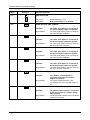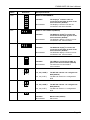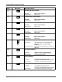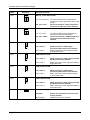
1
EVB9S12XEP100
Evaluation Board
for Freescale
MC9S12XEP100
User’s Manual
Copyright © SofTec Microsystems®. Freescale™ and the Freescale logo are trademarks of Freescale Semiconductor, Inc.
EVB9S12XEP100
Evaluation Board
for Freescale
MC9S12XEP100
(144-Pin LQFP)
User’s Manual
Revision 2.0
Copyright © 2006 SofTec Microsystems®
DC01180
We want your feedback!
SofTec Microsystems is always on the look-out for new ways to improve its Products and
Services. For this reason feedback, comments, suggestions or criticisms, however small,
are always welcome.
Our policy at SofTec Microsystems is to comply with all applicable worldwide safety and
EMC/EMI regulations. Our products are certified to comply to the European New
Approach Directives and the CE mark is applied on all our products.
This product as shipped from the factory has been verified to meet with requirements
FCC as a CLASS A product.
This product is designed and intended for use as a development platform for hardware or
software in an educational or professional laboratory.
In a domestic environment, this product may cause radio interference in which case the
user may be required to take adequate prevention measures.
Attaching additional wiring to this product or modifying the product operation from the
factory default as shipped may effect its performance and cause interference with other
apparatus in the immediate vicinity. If such interference is detected, suitable mitigating
measures should be taken.
SofTec Microsystems
E-mail (general information): [email protected]
E-mail (marketing department): [email protected]
E-mail (technical support): [email protected]
Web: http://www.softecmicro.com
Important
SofTec Microsystems reserves the right to make improvements to this product, its documentation and software routines,
without notice. Information in this manual is intended to be accurate and reliable. However, SofTec Microsystems assumes no
responsibility for its use; nor for any infringements of rights of third parties which may result from its use.
SOFTEC MICROSYSTEMS WILL NOT BE LIABLE FOR DAMAGES RESULTING FROM LOSS OF DATA, PROFITS, USE
OF PRODUCTS, OR INCIDENTAL OR CONSEQUENTIAL DAMAGES, EVEN IF ADVISED OF THE POSSIBILITY
THEREOF.
Trademarks
SofTec Microsystems is a registered trademark of SofTec Microsystems, Spa.
Freescale™ and the Freescale logo are trademarks of Freescale Semiconductor, Inc.
Microsoft and Windows are trademarks or registered trademarks of Microsoft Corporation.
PC is a registered trademark of International Business Machines Corporation.
Other products and company names listed are trademarks or trade names of their respective companies.
EVB9S12XEP100 User's Manual
Contents
1
Introduction 5
1.1
1.2
1.3
1.4
2
Hardware Features 7
2.1
3
Overview 17
Step-by-Step Tutorial 17
Jumpers and Connectors Settings 19
7.1
7.2
8
Overview 15
Standalone Mode 15
Host Mode 15
Application Tutorial 17
6.1
6.2
7
First Connection 11
Operating Modes 15
5.1
5.2
5.3
6
Overview 9
Host System Requirements 9
Installing CodeWarrior Development Studio 9
Installing SofTec Microsystems Additional Components 10
Hardware Setup 11
4.1
5
Evaluation Board Features 7
Software Setup 9
3.1
3.2
3.3
3.4
4
Overview 5
Package Contents 5
Supported Devices 5
Recommended Reading 5
Jumpers 19
Connectors 27
Troubleshooting 31
8.1
8.2
USB Driver Problems 31
Communication Problems between the PC and the Evaluation Board 31
Page 3
EVB9S12XEP100 User's Manual
1 Introduction
1.1 Overview
The EVB9S12XEP100 Evaluation Board has been designed for the evaluation, demonstration
and debugging of the Freescale MC9S12XEP100 microcontroller.
The EVB9S12XEP100 can be used as a standalone application, or via its built-in USB-to-BDM
interface.
1.2 Package Contents
The EVB9S12XEP100 package includes the following items:
The EVB9S12XEP100 evaluation board;
A USB cable;
An universal, 12 V DC power supply;
The SofTec Microsystems “System Software” CD-ROM;
The CodeWarrior Development Studio CD-ROM;
A Quick Start Guide sheet;
This user’s manual.
1.3 Supported Devices
The EVB9S12XEP100 Evaluation Board supports the following devices:
MC9S12XEP100.
1.4 Recommended Reading
Freescale microcontroller-specific datasheets and application notes;
EVB9S12XEP100 Schematic.
Page 5
EVB9S12XEP100 User's Manual
2 Hardware Features
2.1 Evaluation Board Features
The EVB9S12XEP100 board features:
1.
A “MCU” section containing:
A MC9S12XEP100 microcontroller (in 144-pin LQFP package, already
programmed with a demo application);
A clock module, and a crystal oscillator, together with jumpers to select the clock
source;
Four header connectors with all of the MCU signals.
2.
An Expanded Bus connector (DIN41612) replicating most of the MCU signals.
3.
A power supply section containing a 12 V DC barrel input connector and a 3.3/5.0 V
voltage selector for powering the board.
4.
A built-in “USB TO BDM INTERFACE” section which allows the host PC to
communicate with the microcontroller through a standard USB interface.
5.
A BDM connector for interfacing to external in-circuit debuggers.
6.
An “INPUTS” section containing:
Four push-buttons;
One potentiometer;
A light sensor;
A series of jumpers to connect/disconnect the above controls to/from the
microcontroller.
7.
A reset push-button;
8.
An “OUTPUTS” section containing:
Two 5x7 dot-matrix displays;
Four user LEDs;
A series of jumpers to connect/disconnect the above controls to/from the
microcontroller.
Page 7
Hardware Features
9.
A “CAN” section containing five CAN connectors with five CAN transceivers (high speed
and fault tolerant), plus a provision for two additional transceivers, together with a series
of jumpers to select the CAN mode.
10.
A “LIN” section containing six LIN connectors and six LIN transceivers, together with a
series of jumpers to select the LIN mode.
11.
An “RS-232” section containing two RS-232 connectors together with a series of
jumpers to set the RS-232 mode.
12.
A “SERIAL SETTINGS” section containing a series of jumpers to select which MCU pins
are used for the various serial functions.
13.
An “I2C” and “SCI” areas replicating the MCU’s I2C0, I2C1, SCI6 and SCI7 signals.
14.
A prototype area.
2
10
9
1
3
12
11
4
8
14
5
6
7
13
The EVB9S12XEP100 Evaluation Board
Page 8
EVB9S12XEP100 User's Manual
3 Software Setup
3.1 Overview
i
Note: before connecting the Evaluation Board to the PC, it is
recommended that you install all of the required software first (see
below), so that the appropriate USB driver will be automatically found by
Windows when you connect the Evaluation Board.
The Evaluation Board requires that both CodeWarrior Development Studio and SofTec
Microsystems Additional Components be installed in the host PC.
i
Note: CodeWarrior Development Studio must be installed first.
3.2 Host System Requirements
The Evaluation Board is controlled by CodeWarrior Development Studio. The following
hardware and software are required to run the CodeWarrior user interface together with the
Evaluation Board:
A 200-MHz (or higher) PC compatible system running Windows 98, Windows 2000 or
Windows XP;
128 MB of available system RAM plus 1 GB of available hard disk space;
A USB port;
CD-ROM drive for installation.
3.3 Installing CodeWarrior Development Studio
To install the CodeWarrior Development Studio, insert the CodeWarrior CD-ROM into your
computer’s CD-ROM drive. A startup window will automatically appear. Follow the on-screen
instructions.
Page 9
Software Setup
3.4 Installing SofTec Microsystems Additional
Components
The SofTec Microsystems Additional Components install all of the other required components
to your hard drive. These components include:
The Evaluation Board’s USB driver;
The software plug-in for CodeWarrior;
Examples for CodeWarrior;
Evaluation Board’s user’s manual;
Evaluation Board’s schematic;
Additional documentation.
To install the SofTec Microsystems Additional Components, insert the SofTec Microsystems
“System Software” CD-ROM into your computer’s CD-ROM drive. A startup window will
automatically appear. Choose “Install Instrument Software” from the main menu. A list of
available software will appear. Click on the “Additional Components” option. Follow the onscreen instructions.
i
Page 10
Note: to install the Additional Components on Windows 2000 or Windows
XP, you must log in as Administrator.
EVB9S12XEP100 User's Manual
4 Hardware Setup
4.1 First Connection
The Evaluation Board is connected to a host PC through a USB port. Connection steps are
listed below in the recommended flow order:
1.
Install all the required system software as described in the previous section.
2.
Power the board through the barrel connector (12 V DC). The “POWER” LED will turn
on.
3.
Insert one end of the USB cable into a free USB port of the PC.
4.
Insert the other end of the USB cable into the USB connector on the Evaluation Board.
5.
The first time the Evaluation Board is connected to the PC, Windows recognizes the
instrument and starts the “Found New Hardware Wizard” procedure, asking you to
specify the driver to use for the instrument. On Windows XP (SP2) the following dialog
box will appear.
Select the “No, not this time” option and click the “Next >” button.
6.
The following dialog box will appear.
Page 11
Hardware Setup
Click the “Next >” button.
7.
Depending on your Windows settings, the following warning may appear.
i
Note: this warning is related to the fact that the USB driver used by
the Evaluation Board is not digitally signed by Microsoft, and
Windows considers it to be potentially malfunctioning or dangerous
for the system. However, you can safely ignore the warning, since
every kind of compatibility/security test has been carried out by
SofTec Microsystems.
Click the “Continue Anyway” button.
8.
Windows will install the driver files to your system. At the end of the installation, the
following dialog box will appear.
Page 12
EVB9S12XEP100 User's Manual
Click the “Finish” button to exit from the “Found New Hardware Wizard” procedure.
9.
The Evaluation Board’s USB driver is now installed on your system.
Page 13
EVB9S12XEP100 User's Manual
5 Operating Modes
5.1 Overview
The Evaluation Board can work in two modes: “standalone” mode and “host” mode.
5.2 Standalone Mode
In standalone mode, no PC connection is required. The microcontroller is factory programmed
with a sample application.
To run the built-in example:
1.
Verify that all jumpers are in their default position. See the “Jumpers and Connectors
Settings” chapter.
2.
Power the board. The power connector accepts 12 V DC wall plug-in power supply with
a 2.1 mm pin and sleeve plug with positive in the center and sleeve as ground. The
green “POWER” LED on the board should turn on.
3.
Press the “PB4” push-button. The output of the light sensor will be displayed on the two
dot-matrix displays, in a graphical way. The light sensor is placed on the left of the “PB7”
push-button. Cover the sensor with a finger and see the effect on the displays.
4.
Press the “PB5” push-button. The output of the light sensor will be displayed on the two
dot-matrix displays, in a numerical (hexadecimal) way.
5.
Press the “PB6” push-button. The value of the “PAD10” potentiometer will be displayed
on the two dot-matrix displays, in a graphical way.
6.
Press the “PB7” push-button. The value of the “PAD10” potentiometer will be displayed
on the two dot-matrix displays, in a numerical (hexadecimal) way.
5.3 Host Mode
In host mode the program execution is controlled by the host PC through the “USB” connector.
You can use the PC to debug the application by, for example, executing the program step by
step and watching how the microcontroller registers vary, using the provided CodeWarrior
Development Studio.
Page 15
Operating Modes
i
Note: all MCUs in the S12X family contain a single-wire background
debug interface which supports in-circuit programming of on-chip nonvolatile memory. This system does not interfere with normal application
resources. It does not use any user memory or locations in the memory
map. The Background Debug Module (BDM) uses a single-wire
communication interface (via the BKGD line) to allow non-intrusive access
to target system memory and registers.
To work in host mode (using the built-in USB to BDM interface):
Make sure that the board is powered on;
Make sure that the “RESET ENA” and “BKGD ENA” jumpers in the “USB TO BDM
INTERFACE” section are inserted;
Connect the host PC to the board through the provided USB cable.
Page 16
EVB9S12XEP100 User's Manual
6 Application Tutorial
6.1 Overview
This section will provide a step-by-step guide on how to launch your first project and get
started with the CodeWarrior user interface (working in Host Mode).
6.2 Step-by-Step Tutorial
The sample application is the same as the one described in the “Standalone Mode” section
above.
1.
Set up the board so that it works in host mode (see “Host Mode” above).
2.
Ensure that the Evaluation Board is connected to the PC (via the USB cable) and that
the board is powered on.
3.
Start CodeWarrior by selecting it in the Windows Start menu.
4.
From the CodeWarrior main menu, choose “File > Open” and choose the “\Program
Files\Freescale\CW for HC12 V4.5\(CodeWarrior_Examples)\HCS12X\Evaluation
Board Examples\EVB9S12XEP100\C\Demo\Demo.mcp”.
5.
Click “Open”. The Project Window will open.
6.
The code of this example is contained in the “main.c” file. Double click on it to open.
7.
From the main menu, choose “Project > Debug”. This will compile the source code,
generate an executable file and download it to the demo board.
8.
A new debugger environment will open. From the main menu, choose “Run >
Start/Continue”. The program will be executed in real-time.
9.
From the main menu, choose “Run > Halt”. The program execution will stop. The next
instruction to be executed is highlighted in the Source window.
10.
From the main menu, choose “Run > Single Step”. The instruction highlighted in the
Source window will be executed, and the program execution will be stopped immediately
after.
11.
From the main menu, choose “Run > Start/Continue”. The application will restart from
where it was previously stopped.
Congratulations! You have successfully completed this tutorial! You can continue to
experiment with the CodeWarrior user interface and discover by yourself its potentialities. For
an in-depth guide of all of the user interface features, select “Help > CodeWarrior Help” from
CodeWarrior Development Studio’s main menu.
Page 17
EVB9S12XEP100 User's Manual
7 Jumpers and Connectors Settings
7.1 Jumpers
Name
Reference
Description/Pinout
MODA=1
J106
Installed:
Not Installed:
MODB=1
J107
Installed:
Not Installed:
J108
MODA line pulled to VDD
MODA line tied to ground by internal pull
down (default)
1
MODB line pulled to VDD
MODB line tied to ground by internal pull
down (default)
MODC SELECTION
2
3
1-2 (“1”):
2-3 (“0”):
J109
1
MODC pulled to VDD via a 4.7 KOhm
resistor (default)
MODC line pulled to ground via a 4.7
KOhm resistor
VRH SELECTION
2
3
J110
1
1-2 (“VDDA”):
2-3 (“USER”):
VRH tied to VDDA (default)
VRH connected to the J103 connector
VRL SELECTION
2
3
J111
1
1-2 (“GND”):
2-3 (“USER”):
VRL tied to ground (default)
VRL connected to the J104 connector
OSC SELECTION
2
3
J112
1-2 (“CRYSTAL”): Crystal oscillator selected (default)
2-3 (“CLOCK”):
Clock oscillator selected
XCLKS#=0
Installed:
Not Installed:
XCLKS# pin pushed to ground. Full-swing
Pierce oscillator or external clock source
selected.
XCLKS# pulled to VDD. Loop controlled
Pierce oscillator selected. (default)
Page 19
Jumpers and Connectors Settings
Name
J102
Reference
1
Description/Pinout
VDD SELECTION
2
3
J204
1-2 (“3V3”):
2-3 (“5V”):
PUSH-BUTTON “PB4” ENABLE
Installed:
Not Installed:
J205
Not Installed:
Not Installed:
Not Installed:
Not Installed:
The “PAD10” potentiomenter is
connected to the microcontroller’s
PAD10 line (default)
The “PAD10” potentiomenter is not
connected to the microcontroller’s PAD10
line
PHOTO RESISTOR ENABLE
Installed:
Not Installed:
Page 20
The “PB7” push-button is connected to
the microcontroller’s PB7 line (default)
The “PB7” push-button is not connected to
the microcontroller’s PB7 line
POTENTIOMETER ENABLE
Installed:
J209
The “PB6” push-button is connected to
the microcontroller’s PB6 line (default)
The “PB6” push-button is not connected to
the microcontroller’s PB6 line
PUSH-BUTTON “PB7” ENABLE
Installed:
J208
The “PB5” push-button is connected to
the microcontroller’s PB5 line (default)
The “PB5” push-button is not connected to
the microcontroller’s PB5 line
PUSH-BUTTON “PB6” ENABLE
Installed:
J207
The “PB4” push-button is connected to
the microcontroller’s PB4 line (default)
The “PB4” push-button is not connected to
the microcontroller’s PB4 line
PUSH-BUTTON “PB5” ENABLE
Installed:
J206
Board powered by 3.3 V
Board powered by 5.0 V (default)
The photoresistor network is connected
to the microcontroller’s PAD11 analog
input (default)
The photoresistor network is not connected
to the microcontroller
EVB9S12XEP100 User's Manual
Name
Reference
J210
Description/Pinout
DISPLAY ROW ENABLE
1
Installed:
Not Installed:
The displays’ common rows are
connected to the PA[6..0] ports of the
microcontroller (default)
The displays’ common rows are not
connected to the microcontroller.
DISPLAY COL ENABLE (DISP201)
J211
1
Installed:
Not Installed:
The DISP201 display’s columns are
connected to the PC[4..0] ports of the
microcontroller (default)
The DISP201 display’s columns are not
connected to the microcontroller.
DISPLAY COL ENABLE (DISP202)
J212
1
Installed:
Not Installed:
J213
LED ENABLE
1
Installed:
Not Installed:
J303
1
2
3
4
5
6
1
2
3
4
5
6
1-3, 2-4 (“DCE”):
The RS-232 channel 0 is configured as
DCE (default)
The RS-232 channel 0 is configured as
DTE
SCI1 DTE/DCE SELECTION
1-3, 2-4 (“DCE”):
3-5, 4-6 (“DTE”):
J305
The LEDs are connected to PB[3..0]
ports of the microcontroller (default)
The LEDs are not connected to
microcontroller.
SCI0 DTE/DCE SELECTION
3-5, 4-6 (“DTE”):
J304
The DISP202 display’s columns are
connected to the PD[4..0] ports of the
microcontroller (default)
The DISP202 display’s columns are not
connected to the microcontroller.
The RS-232 channel 1 is configured as
DCE (default)
The RS-232 channel 1 is configured as
DTE
LIN MASTER NODE0 ENABLE
Installed:
Not Installed:
Master node (default)
Slave node
Page 21
Jumpers and Connectors Settings
Name
Reference
Description/Pinout
LIN MASTER NODE1 ENABLE
J307
Installed:
Not Installed:
LINE MASTER NODE2 ENABLE
J309
Installed:
Not Installed:
Master node (default)
Slave node
LIN MASTER NODE3 ENABLE
J311
Installed:
Not Installed:
Master node (default)
Slave node
LIN MASTER NODE4 ENABLE
J313
Installed:
Not Installed:
Master node (default)
Slave node
LIN MASTER NODE5 ENABLE
J315
Installed:
Not Installed:
J317
Master node (default)
Slave node
1
Master node (default)
Slave node
LIN TRANSCEIVER SUPPLY SELECTION
2
3
J318
1-2 (“12V”):
LIN transceivers are supplied by the
board’s internal 12 V DC voltage
(default)
2-3 (“LIN NETW.”): LIN transceivers supplied by the LIN bus’s
VBAT line
LIN SUPPLY ENABLE
Installed:
Not Installed:
J319
LIN2 RX ENABLE
Installed:
Not Installed:
J320
PJ0/RXD2 microcontroller line
connected to LIN2 transceiver (default)
PJ0/RXD2 microcontroller line floating
LIN2 TX ENABLE
Installed:
Not Installed:
Page 22
LIN bus is powered by the board’s
internal 12 V DC voltage (default)
LIN bus is self-powered
PJ1/TXD2 microcontroller line
connected to LIN2 transceiver (default)
PJ1/TXD2 microcontroller line floating
EVB9S12XEP100 User's Manual
Name
Reference
Description/Pinout
LIN4 RX ENABLE
J321
Installed:
Not Installed:
LIN4 TX ENABLE
J322
Installed:
Not Installed:
Installed:
Not Installed:
Installed:
Not Installed:
1
2
3
4
5
6
1
2
3
4
5
6
1
2
3
4
5
6
PH7/TXD5 microcontroller line
connected to LIN5 transceiver (default)
PH7/TXD5 microcontroller line floating
RS-232_0 SCI0/6 SELECTION
1-3, 2-4 (“SCI6”):
3-5, 4-6 (“SCI0”):
J332
PH6/RXD5 microcontroller line
connected to LIN5 transceiver (default)
PH6/RXD5 microcontroller line floating
LIN5 TX ENABLE
J324
J331
PH5/TXD4 microcontroller line
connected to LIN4 transceiver (default)
PH5/TXD4 microcontroller line floating
LIN5 RX ENABLE
J323
J330
PH4/RXD4 microcontroller line
connected to LIN4 transceiver (default)
PH4/RXD4 microcontroller line floating
The RS-232 channel 0 transceiver is
connected to the microcontroller’s SCI6
peripheral (default)
The RS-232 channel 0 transceiver is
connected to the pin 1 and pin2 of the J331
jumper
RS-232_0/LIN0 SELECTION
1-3, 2-4 (“RS-232”): The microcontroller’s SCI0 peripheral is
connected to the pin 5 and pin 6 of the J330
jumper
3-5, 4-6 (“LIN”):
The microcontroller’s SCI0 peripheral is
connected to LIN0 transceiver (default)
RS-232_1 SCI1/7 SELECTION
1-3, 2-4 (“SCI7”):
3-5, 4-6 (“SCI1”):
The RS-232 channel 1 transceiver is
connected to the microcontroller’s SCI7
peripheral (default)
The RS-232 channel 1 transceiver is
connected to the pin 1 and pin2 of the J333
jumper
Page 23
Jumpers and Connectors Settings
Name
J333
J334
Reference
1
2
3
4
5
6
1
2
3
4
5
6
Description/Pinout
RS-232_1/LIN1 SELECTION
1-3, 2-4 (“RS-232”): The microcontroller’s SCI1 peripheral is
connected to the pin 5 and pin 6 of the J332
jumper
3-5, 4-6 (“LIN”):
The microcontroller’s SCI1 peripheral is
connected to LIN1 transceiver (default)
CAN3/LIN3 SELECTION
1-3, 2-4 (“LIN”):
3-5, 4-6 (“CAN”):
J401
1
The microcontroller’s SCI3 peripheral is
connected to the LIN3 transceiver
The microcontroller’s CAN3 peripheral is
connected to the CAN3 transceiver
(default)
CANH0 SELECTION
2
3
1-2 (“U401”):
2-3 (“U406”):
J402
1
CAN0 connector’s CANH signal
provided by U401 transceiver (default)
CAN0 connector’s CANH signal provided
by U406 transceiver
CANL0 SELECTION
2
3
1-2 (“U401”):
2-3 (“U406”):
J404
1
CAN0 connector’s CANL signal provided
by U401 transceiver (default)
CAN0 connector’s CANL signal provided by
U406 transceiver
CANH1 SELECTION
2
3
1-2 (“U402”):
2-3 (“U407”):
J405
1
CAN1 connector’s CANH signal
provided by U402 transceiver (default)
CAN1 connector’s CANH signal provided
by U407 transceiver
CANL1 SELECTION
2
3
1-2 (“U402”):
2-3 (“U407”):
J407
CAN2 VCC ENABLE
Installed:
Not Installed:
Page 24
CAN1 connector’s CANL signal provided
by U402 transceiver (default)
CAN1 connector’s CANL signal provided by
U407 transceiver
Powers the CAN2 transceiver with a 5 V
voltage (default)
CAN2 transceiver not powered
EVB9S12XEP100 User's Manual
Name
J409
Reference
Description/Pinout
CAN4 VCC ENABLE
Installed:
Not Installed:
J412
CAN3 RESET ENABLE
Installed:
Not Installed:
J413
Not Installed:
Not Installed:
Not Installed:
Not Installed:
Microcontroller’s PM2/RXCAN1 line
connected to CAN1 transceiver (default)
Microcontroller’s PM2/RXCAN1 line floating
CAN1 TX ENABLE
Installed:
Not Installed:
J418
Microcontroller’s PM1/TXCAN0 line
connected to CAN0 transceiver (default)
Microcontroller’s PM1/TXCAN0 line floating
CAN1 RX ENABLE
Installed:
J417
Microcontroller’s PM0/RXCAN0 line
connected to CAN0 transceiver (default)
Microcontroller’s PM0/RXCAN0 line floating
CAN0 TX ENABLE
Installed:
J416
Microcontroller’s PE1 line connected to the
CAN3 transceiver’s INTB line
CAN3 transceiver INTB line floating
(default)
CAN0 RX ENABLE
Installed:
J415
Microcontroller’s RESET# line connected to
the CAN3 transceiver’s RESET# line
CAN3 transceiver RESET# line floating
(default)
CAN3 INTERRUPT ENABLE
Installed:
J414
Powers the CAN4 transceiver with a 5 V
voltage (default)
CAN4 transceiver not powered
Microcontroller’s PM3/TXCAN1 line
connected to CAN1 transceiver (default)
Microcontroller’s PM3/TXCAN1 line floating
CAN2 RX ENABLE
Installed:
Not Installed:
Microcontroller’s PM4/RXCAN2 line
connected to CAN2 transceiver (default)
Microcontroller’s PM4/RXCAN2 line floating
Page 25
Jumpers and Connectors Settings
Name
J419
Reference
Description/Pinout
CAN2 TX ENABLE
Installed:
Not Installed:
J420
CAN4 RX ENABLE
Installed:
Not Installed:
J421
Not Installed:
Not Installed:
Microcontroller’s RESET# line
connected to the “USB TO BDM
INTERFACE” (default)
Microcontroller’s RESET# line not
connected to the “USB TO BDM
INTERFACE”
BKGD ENABLE (USB TO BDM)
Installed:
Not Installed:
Page 26
Microcontroller’s PJ7/TXCAN4 line
connected to CAN4 transceiver (default)
Microcontroller’s PJ7/TXCAN4 line floating
RESET ENABLE (USB TO BDM)
Installed:
J503
Microcontroller’s PJ6/RXCAN4 line
connected to CAN4 transceiver (default)
Microcontroller’s PJ6/RXCAN4 line floating
CAN4 TX ENABLE
Installed:
J502
Microcontroller’s PM5/TXCAN2 line
connected to CAN2 transceiver (default)
Microcontroller’s PM5/TXCAN2 line floating
Microcontroller’s BKGD line connected
to the “USB TO BDM INTERFACE”
(default)
Microcontroller’s BKGD line not connected
to the “USB TO BDM INTERFACE”
EVB9S12XEP100 User's Manual
7.2 Connectors
Name
Reference
Description/Pinout
MCU I/O Connectors
J101,
J102,
J103,
J104
See schematic for pin explanation
J105
1
2
3
4
5
6
BDM Connector
1.
2.
3.
4.
5.
6.
BKGD
GND
N.C.
RESET
N.C.
VDD
Test Points
J113,
J203,
J325,
J422,
J504
J201
12 V DC Power Supply Input Connector (2.1 mm Barrel)
2
1
1.
2.
J301
12 V DC
GND
RS-232_0 Connector
9
6
5
1
J302
1.
2.
3.
4.
5.
6.
7.
8.
9.
N.C.
TX or RX (see J303 jumper)
RX or TX (see J303 jumper)
N.C.
GND
N.C.
N.C.
N.C.
N.C.
RS-232_1 Connector
9
5
6
1
1.
2.
3.
4.
5.
6.
7.
8.
9.
N.C.
TX or RX (see J304 jumper)
RX or TX (see J304 jumper)
N.C.
GND
N.C.
N.C.
N.C.
N.C.
Page 27
Jumpers and Connectors Settings
Name
J306
Reference
Description/Pinout
LIN0 Connector
1
2
1.
2.
3.
3
J308
LIN1 Connector
1
J310
VBAT – LIN Bus Power Supply
LIN – LIN Signal
GND
1.
2.
3.
4.
GND
GND
VBAT – LIN Bus Power Supply
LIN – LIN Signal
LIN2 Connector
1
2
1.
2.
3.
3
J312
LIN3 Connector
1
J314
VBAT – LIN Bus Power Supply
LIN – LIN Signal
GND
1.
2.
3.
4.
GND
GND
VBAT – LIN Bus Power Supply
LIN – LIN Signal
LIN4 Connector
1
2
1.
2.
3.
3
J316
LIN5 Connector
1
J326
VBAT – LIN Bus Power Supply
LIN – LIN Signal
GND
1
1.
2.
3.
4.
GND
GND
VBAT – LIN Bus Power Supply
LIN – LIN Signal
SCI6 Connector
2
1.
2.
J327
1
RX
TX
SCI7 Connector
2
1.
2.
Page 28
RX
TX
EVB9S12XEP100 User's Manual
Name
J328
Reference
Description/Pinout
I2C0 Connector
1
2
1.
2.
J329
SDA
SCL
I2C1 Connector
1
2
1.
2.
1
J403
CAN0 Connector
1.
2.
3.
4.
1
J406
CANH
CANL
GND
N.C.
CAN1 Connector
1.
2.
3.
4.
CANH
CANL
GND
N.C.
CAN2 Connector
J408
1
2
3
1.
2.
3.
1
J410
CANH
GND
CANL
CAN4 Connector
1.
2.
3.
4.
CANH
CANL
GND
N.C.
CAN3 Connector
J411
1
2
3
1.
2.
3.
J423
SDA
SCL
1c
CANH
GND
CANL
Expanded Bus Connector
1b
1a
DIN41612 female type R (see schematic for pin explanation)
Page 29
Jumpers and Connectors Settings
Name
J501
Reference
Description/Pinout
USB Connector
1.
2.
3.
4.
Page 30
5 V DC USB Bus Power Supply Line
USB DUSB D+
GND
EVB9S12XEP100 User's Manual
8 Troubleshooting
8.1 USB Driver Problems
If you connected the Evaluation Board to the PC before installing the SofTec Microsystems
Additional Components, the Evaluation Board’s USB driver may not have been correctly
installed on your system. Unplugging and replugging the USB cable is of no use, since
Windows has marked the device as “disabled”. As a consequence, the PC cannot
communicate with the Evaluation Board.
To restore the USB driver (provided the SofTec Microsystems Additional Components have
been installed), perform the following steps under Windows XP:
1.
Connect the Evaluation Board to the PC.
2.
Open the Control Panel (Start > Settings > Control Panel).
3.
Open the “System” options.
4.
Select the “Hardware” tab.
5.
Click the “Device Manager” button.
6.
The “uDART In-Circuit Debugger” device will be shown with an exclamation mark next
to it. Double click on this device.
7.
In the “General” tab, click the “Reinstall Driver” button. Follow the on-screen
instructions.
8.2 Communication Problems between the PC and the
Evaluation Board
1.
Make sure that the “BKGD ENA” and “RESET ENA” jumpers in the “USB TO BDM
INTERFACE” section are inserted.
2.
Make sure that the board is powered (verify that the “POWER” LED is turned on).
3.
Make sure that a correct clock source is selected.
Page 31
EVB9S12XEP100
Evaluation Board
for Freescale
MC9S12XEP100
User’s Manual
Copyright © SofTec Microsystems®. Freescale™ and the Freescale logo are trademarks of Freescale Semiconductor, Inc.