1
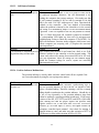
PROPER STEPPING SEQUENCE:
1. Car is at floor, DZ indicator LED is on AND STU/STD are also lit, indicating door zone is
active and stepping inputs are not.
2. DZ indicator goes off, now STU (STD for down) indicator will go off as car engages stepping
vane, and position indicator output reflects new floor position. Further activation of STU/STD will be
ignored until after DZ is cycled on/off "re-arming" electronic selector for next floor stepping.
III.3. MICROPROCESSOR TROUBLESHOOTING
The basic idea of this section is to determine if the Computer Logic Check-out indicates a faulty
board, and if so which, if any, of the microprocessor system logic boards is faulty, so that a good board
may be substituted. No attempt has been made to diagnose specific problems that might be on any
particular board, since to do so requires specialized test equipment not generally available to elevator
service mechanics.
Let us assume that you have come to the conclusion that an output is not coming out of the
computer system when conditions appear such that it should. At this point it becomes necessary to
determine if the computer is trying to turn on the output or not, and if not, what is preventing it from doing
so.
To find out what the computer is "thinking" or trying to do, we need to look into its memory itself.
This is done by using the ON-BOARD diagnostics unit in the manner described in the Field Reprogramming manual. You may now review the re-programming manual. Refer particularly to the
"Memory Flags" table listing for viewing inputs and outputs.
As an example, let us say that it is observed that the door open function output fails to operate the
door open relay DO in response to a door opening input signal. It is observed that the DOF door open
function output LED indicator does not turn-on. We now set the diagnostics switches as described, and
locate the DOF function near the bottom of the Memory Flags Listing page which indicates an address of
9B for DOF. We then set the MSA, LSA switches to this 9B respectively and observe that, indeed, the
LED indicator corresponding to the DOF position is off. This tells us the computer is not turning on the
door open output. This must mean that either the open signal input (say door open button DOB
address=81) is not coming in, or computer thinks doors are already fully open (DOLF -door open limit
front input is zero, address 80), or it is otherwise unsafe to open doors (DZ=0 or HIR=1). Inspection of
these flags will indicated either that an input was not supplied to the system properly, or that the computer
can not see it. In the later case we suspect that the I/O board (specially if DOB and DOLF do not track
input signals), or ribbon cable connecting it to computer board is faulty.
In a manner similar to the example above, any other output/input can be traced to the computer
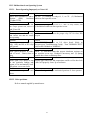
memory in search for the faulty section. The section below illustrates the logic involved in the computer to
process the indicated outputs and signals.
23