1
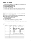
10. Troubleshooting Problem Probable Reasons Available Solutions 1. Alarm does not dial not arming do arming operation out. alerting phone incorrectly set re-set according to the spec. parts improperly installed Relocation of parts code no match re-code SIM card overdue 5. Top up the SIM card password or SMS input incorrect retry password / SMS or reset 2. cannot operate by phone password SMS message not recorded record SMS message 4. remote control coding un-matched with the Panel re-learn the remote control (keyfob) out of order insufficient battery power change battery to correct type battery has poor contact or voltage contact 3. no message indication when alerting www.boatsteward.co.uk to change the matched remote control (keyfob) 5. infrared detector out low power Renew battery siren plug or jack in short circuit or repair or change plug or jack of order 6. siren without sound broken-line change the jack line siren out of order activate siren by command closed siren by command use another siren to double check 7Panel not receiving a nearby emitter is sending code detector Panel receiver stoppage standby battery of the Panel insufficient move one detector next to panel and try again identify the interfering source and eliminate it check Panel power is on 8. the signal LED SIM card un-loaded reload SIM card blinking quickly SIM card is setting PIN code cancel PIN code of SIM GSM signal weak change to a place with a stronger signal Suggested TEXT TEMPLATES for your phone; TEXT Set alarm 12341# ALARM ON Unset Alarm 12340# ALARM OFF Relay On (Heating) 12343# HEATING ON Relay Off (Heating) 12344# HEATING OFF Alarm Status Enquiry 123420# ALARM STATUS Alert & Alerting Number 123421# ALERT/ALERTING No. Add Phone No1 .for SMS 123437***********# 1st SMS phone No. Add Phone No.2 for SMS 123438***********# 2nd SMS phone No. Clydebuilt Marine Electronics www.cbme.co.uk boatsteward® User manual 1. System Foreword This wireless GSM intelligent monitoring system is built on leading microprocessor technology with advanced GSM digital signal processing power. It is a highly integrated system of text messages, multiple mode’s of wireless coding, long-distance appliances controlling, short messages identification and other technologies. When alarming, it will automatically inform of the alerting device and location through text messages. It is stable, reliable and safe. With human manipulation and telecom phone line removed, it can be comprehensively applied to places at which wire phone networks can NOT cover the protection needed. It is able to protect users property and personnel safety as well as monitoring the boat. 2. General introduction of functions ■ten zones set as normal, stay, intelligent, emergency, open or closed types, etc.; ■Using phone (cellphone) or SMS to configure & control the panel remotely. ■ Four wired zones, six wireless zones, each zone can be equipped with many accessories. ■ Three groups of phone numbers for SMS messages. ■One normally open signal output, which can be externally linked to operate heating etc. ■ Built-in short message contents. Short message content from alarming zone can be amended. ■Wireless intelligent study coding, compatible with 2,262 normal encoding and a million group encoding, convenient and flexible for adding or reducing accessories. ■Telephone long-distance telecontrol for arming, disarming, and controlling appliances. ■EEPROM information protection, information will never be lost. ■Built-in NI-Lithium battery will automatically be transferred to stand-by after outage with short message prompting. ■DC supply and(standby), twenty-four-hour normal guarding and unbroken service. ■Panel using double, triple or quadruple GSM/GPRS wireless industry module, (depending on model) which is stable and reliable. 3. Arming / Disarming Operations 3.1 Arming Arming means that all detectors are working. When something triggers the detectors, the alerting system will alarm at once. After arming operation, the Set light on the panel will remain on, until it has been reset by the remote control or by SMS. Remote control operation: press the arming key in the remote-control-unit once will Set. Phone :Send SMS 12341# and receive a confirmation TEXT 3.2. Stay arming Stay is for arming the ,Gas detector ,Smoke detector and bilge alarm (but not the PIR or Proximity switch). When armed the Set light on the panel will flicker. Remote control operation: press Arming key and the Stay key in the remote-control-unit (once each) will Set. 3.3 Disarming operation Disarming means that when the panel alerts, it can stop the alerting or put the system into disarm status. After disarming, even triggering detectors can NOT make the panel alert,( except for the detectors in emergency Defense zone’s i.e. MOB fob) or the emergency key in the remote-control-unit. After disarming, arming light goes out. Remote control operation: press the disarming key in the remote-control-unit once will reset. Phone :Send SMS 12340# and receive a confirmation TEXT 3.4 Emergency alerting If an emergency arises, press the emergency key on the remote-control-unit or the MOB (man overboard fobs) this in turn will operate the sounder and send a text message. 8. Leaving-factory default Password: 1234 Long-distance control: Open Ringing times: once Siren timing: 1 minute Aural remote control siren: open Delayed arming: 0second Delayed alerting: 0 second 9. System Specification A 230v > 12V dc adaptor is supplied, which enables the unit to be set up at home and/or plugged into the shore power in order to monitor this supply. Input voltage: DC 9V – 12V Standby current: <25mA Alerting current: <450 mA Wireless frequency: 315/433/868/915MHZ, 2262/1.5--4.7M, EV1527/300K. GSM SYSTEM: supporting GSM850/900/1800/1900MHz 2G Sim Card only Standby battery: NI-HI AAA*6 DC7.4V Siren loudness: 110dB Accessories parameters: this panel is compatible with PT2262 code; PT2240 code and EV1527 shorten code. Servicing The PIR’s have an on/off switch on the side which can be switched off when onboard so as to prolong the battery life. Although the battery life of individual detectors can vary, it is recommended that the batteries be renewed on an annual basis and be tested frequently. The MOB fobs after prolonged immersion or for annual service (in order to maintain their integrity) should be returned to ; CBME, Clyde Marina Ardrossan Ayrshire Scotland KA22 8DB Operation Commands & Programming Commands 0# DISARM SMS Messages disarming, send SMS Messages 12340# 1# ARM SMS Messages arming, send SMS Messages 12341# 2# STAY ARM SMS Messages STAY arming, send SMS Messages 12342# 3# RELAY ON SMS Messages Relay closing, send SMS Messages 12343# 4# RELAY OFF SMS Messages Relay opening, send SMS Messages 12344# [20]+[#] Find arming and disarming status. send SMS Messages 123420# [21]+[#] Find alerting number and alert-receiving number configured in the panel. send SMS Messages 123421# [80]+[#] Used to inquire as to SMS Messages contents from all Defense zones. For example: send SMS Messages 123480# [81]+[Defense zone one, Used to set SMS Messages content given by Panel when the first Defense zone SMS Messages content]+[#] alerts. SMS Messages content can NOT exceed twelve characters. For example: send SMS Messages “123481 Man overboard # ” At that time, when the first Defense zone is triggered, the SMS Messages of “Man overboard” will be sent as a short-message to alarming number. [82]+[Defense zone two, Used to set SMS Messages content given by Panel when the second Defense SMS Messages content]+[#] zone alerts. ditto [83]+[Defense zone two, Used to set SMS Messages content given by Panel when the third Defense zone SMS Messages content]+[#] alerts. ditto [84>89]+[Messages for The forth to ninth Defense zone can be inferred as above. Z4>Z9]+[#] [90]+[Defense zone ten, SMS Used to set SMS Messages content given by Panel when the tenth Defense zone Messages content]+[#] alerts. ditto 7. Note: Difference between Defense Zone Types: NORMAL Defense Zone: the Panel only works on the arming status. When disarming, there is no response. STAY Defense zone: can be shut off solely through the remote control (keyfob) to ensure no external influence will cancel this function.. INTELLIGENT Defense zone: if the detector in the Defense zone is triggered only once, it will not immediately alarm. But if being triggered once again within 30 seconds after the first triggering, it will alarm immediately. EMERGENCY Defense zone: no matter on arming or disarming status, if detector is triggered it will alert. Usually used in connection with Smoke Detectors, Gas Detectors and emergency button, etc. CLOSED Defense zone: no matter arming or disarming status, detectors will not alert even being triggered. 4. Installation and debugging ■host and 2G SIM card installation The panel should be installed in a central zone of the monitored area so as to make sure that all wireless detectors can be best received. Take care to keep away from large-scale metal objects or appliances with high-frequency interference.. The control panel : Speaker optional for future use Remote Control Unit Sim Card Installation Connection of wired sensors & relay Relay connect NO and C between the load to be controlled Sensors: Bilge level switch Gas alarm relay connect connect Gnd. To 7 Gnd. To 8 Zone 9 connect Gnd. To 9 Zone 10 connect Gnd . To 10 5. The GSM host settling First-time energization Ensure the SIM card (use a 2G only), all wired sensors (if applicable) and antenna are correctly installed, then connect the DC power. Upon power up, the alarm panel will carry a self-test sequence as below: Six Defense Zones’ LED and two Functional LED’s on front panel will flash in order( once each) and end with a buzzer long “Beep”. The GSM Signal LED flashes with one second interval for checking the GSM signal. If GSM network detected all right, “Beep” sound stops and Signal LED becomes flashing every three seconds, the GSM signal and SIM card are all confirmed normal, system is READY. Now, switch the stand-by battery switch to “ON”.. ■ indicating information Short “Beep” once Key-pressing indication Long “Beep” once Confirm receipt of a key stroke Continuous short “Beep” for 2 times Correct command received Continuous short “Beep” for 3 times Error in command “Beep” at moderate intervals SIM card not found Defense Zone Always lit Defense zone alerting LED Blinking Defense zone coming into delayed Buzzer alerting Arming LED Always lit Arming status Blinking quickly Stay safe arming status Blinking slowly Coming into delayed arming status GSM signal Blinking every 1 second GSM signal weak, or SIM card not found LED Blinking every 3 seconds GSM module, and SIM card working properly Not lit Without electricity Inputing SMS called number [do this now ] [37]+[ user number]+[#] Example; mobile number you wish to be sent SMS text is 07974699999 Send text 12343707974699999# to the SIM number in the monitor panel Default password [ 1234]code no.[37]mobile number to be alerted [07974699999]+# To change the password, follow instructions below; [50]+[new password]+[#] Modify user operation password For example : If user wants to set new user password as 4321, please send SMS message 1234504321#, or using phone input 1234#504321# 6. SMS programming ■All programming for this panel are accomplished through cell phone call to the host GSM card, and sending short messages.. On working status, and the GSM network detection is normal. Send the following TEXT commands. 1) General command pattern sent via SMS is [password] + [command] + [parameter] + # e.g. setting SMS phone no. 1234379999999# [37]+[ user number]+[#] Add (or delete) 1st group of phone number for receiving SMS messages Example: if the user wants to add phone number 12345678, send This is the first ( and SMS Messages 12343712345678#, or using phone should input possibly only ) 1234 # 37 12345678 # programming to do. Example: if the user wants to delete second-group number, send SMS Messages 123437#, or using phone should input 1234 # 37 # [38]+[ user number]+[#] Add (or delete) 2nd group of phone number for receiving SMS messages [39]+[ user number]+[#] Add (or delete) 3rd group of phone number for receiving SMS messages SMS on setting as follow: [12]+[0/1]+[#] Disable and enable SMS Messages function 0 means not activated. 1 means activated Example: to disable SMS Messages function, send SMS Messages 1234120#, or using phone should input 1234 # 12 0 # EASY INSTALLATION INSTRUCTIONS 1 Mount monitor panel where indication lights can be readily seen 2 Mount bilge level switch in centerline of boat and above any residual bilge water. Insert 1 wire from the bilge level switch and one wire from the alarm cable into the two holes in the crimp and compress with pliers. This will connect the two wires and the surplus silicone grease will be expelled.(no need to strip insulation). Repeat this process with the second wire. Waterproof Crimps 1 If using a wireless bilge switch, ensure the wireless module is mounted as high as possible to safeguard against water ingress. 3 Mount smoke detector in cabin away from galley area 4 Mount PIR as high as is practical above the sole. The sensor should face the detected area at 90° for best coverage 5 Proximity switch; Fix magnet to locker door or washboard and fix transmitter to fixed side, maintaining 6mm or less gap between edges ( see operating light on/off ) 6 Run supply cable from the battery you wish to monitor and connect via fuse on + lead 7 Run alarm cable from bilge level switch and gas detector to panel 7/ gnd & 8/ gnd. 8 Insert SIM card and energise supply 9 When the panel settles with GSM light flashing every 3 seconds put panel switch ON 10 Operate the panel with the remote control and trigger all sensors individually 11 Operate panel with mobile phone and check operation