1
DA-683 Windows Embedded Standard 7
Software Manual
First Edition, April 2014
www.moxa.com/product
© 2014 Moxa Inc. All rights reserved.
DA-683 Windows Embedded Standard 7
Software Manual
The software described in this manual is furnished under a license agreement and may be used only in accordance with
the terms of that agreement.
Copyright Notice
© 2014 Moxa Inc. All rights reserved.
Trademarks
The MOXA logo is a registered trademark of Moxa Inc.
All other trademarks or registered marks in this manual belong to their respective manufacturers.
Disclaimer
Information in this document is subject to change without notice and does not represent a commitment on the part of
Moxa.
Moxa provides this document as is, without warranty of any kind, either expressed or implied, including, but not limited
to, its particular purpose. Moxa reserves the right to make improvements and/or changes to this manual, or to the
products and/or the programs described in this manual, at any time.
Information provided in this manual is intended to be accurate and reliable. However, Moxa assumes no responsibility for
its use, or for any infringements on the rights of third parties that may result from its use.
This product might include unintentional technical or typographical errors. Changes are periodically made to the
information herein to correct such errors, and these changes are incorporated into new editions of the publication.
Technical Support Contact Information
www.moxa.com/support
Moxa Americas
Moxa China (Shanghai office)
Toll-free: 1-888-669-2872
Toll-free: 800-820-5036
Tel:
+1-714-528-6777
Tel:
+86-21-5258-9955
Fax:
+1-714-528-6778
Fax:
+86-21-5258-5505
Moxa Europe
Moxa Asia-Pacific
Tel:
+49-89-3 70 03 99-0
Tel:
+886-2-8919-1230
Fax:
+49-89-3 70 03 99-99
Fax:
+886-2-8919-1231
Moxa India
Tel:
+91-80-4172-9088
Fax:
+91-80-4132-1045
Table of Contents
1.
Introduction ...................................................................................................................................... 1-1
Software Components ......................................................................................................................... 1-2
2.
System Initialization ......................................................................................................................... 2-1
Create a New User Account .................................................................................................................. 2-2
3.
Enabling Embedded Filters ................................................................................................................ 3-1
Enhanced Write Filter .......................................................................................................................... 3-2
Overview .................................................................................................................................... 3-2
Enabling Enhanced Write Filter ...................................................................................................... 3-3
Committing Data and/or Disabling EWF .......................................................................................... 3-4
File-Based Write Filter ......................................................................................................................... 3-5
Overview .................................................................................................................................... 3-5
Configuring File-Based Write Filter ................................................................................................. 3-5
Excluding Files from FBWF Protection ............................................................................................. 3-7
Managing Temporary Files Cached in the Overlay ............................................................................ 3-9
4.
Customizable Sample Code ............................................................................................................... 4-1
Sample Code for Customizing the DA-683 .............................................................................................. 4-2
The DIO Control Walkthrough ....................................................................................................... 4-2
The LED Control Walkthrough ....................................................................................................... 4-3
Watchdog Control Code ....................................................................................................................... 4-4
The Watchdog Control Code Walkthrough ....................................................................................... 4-4
5.
System Recovery ............................................................................................................................... 5-1
Overview: Setting Up the Recovery Environment .................................................................................... 5-2
Step 1: Prepare the USB drive .............................................................................................................. 5-2
Step 2: Setting the BIOS to Boot via USB .............................................................................................. 5-3
Step 3 (opt.): Create a Custom System Image ....................................................................................... 5-4
Step 4: Reset BIOS to Original State ..................................................................................................... 5-7
Step 5: Perform a Test Restoration ....................................................................................................... 5-8
A.
Sample Code for DA-683 Customization ............................................................................................ A-1
The DIO Control Sample Code .............................................................................................................. A-2
The LED Control Sample Code .............................................................................................................. A-4
The Watchdog Control Sample Code ...................................................................................................... A-6
1
1.
Introduction
Thank you for buying Moxa’s DA-683 rackmount computer. It comes with the Windows Embedded Standard 7
software platform, providing a simple and familiar development environment for on-board train applications.
Software Components
Software Components
Refer to the following table to review the software components of your Windows Embedded Standard 7
operating system.
Windows Embedded Standard 7
Core OS:
• 32-bit support
• Remote Client
• Remote Procedure Call
Applications and Services Development:
• .Net Framework 3.5
• COM+ Application Support
• Remote Desktop Protocol 7.1
• MSMQ
• COM OLE Application Support
Internet Services:
• Internet Explorer 8.0
• IIS 7.0
File Systems and Data Store:
• Windows Data Access Components
• Windows Backup and Restore
Diagnostics:
• Common Diagnostic Tools
• Problem Reports and Solutions
Fonts:
Chinese (Trad. and Simp.), Japanese, Korean, Western, Middle Eastern, South-East and South Asian
Graphics and Multimedia:
• MPEG DTV-DVD Audio Decoder (MPEG-2, AAC)
• Windows Media Video VC-1 (WMV) Codecs
• MPEG Layer-3 Audio Codecs(MP3)
• DirectX and Windows Device Experience
• MPEG4 Decoders
• Windows Media Player 12
International:
• IME Simplified Chinese Support
• IME Japanese Support
• IME Traditional Chinese Support
• IME Korean Support
Management:
• Group Policy Management
• Windows Management Instrument (WMI)
• Windows Update
Networking:
• Extensible Authentication Protocol (EAP)
• Network and Sharing Center
• Internet Authentication Service
• Quality of Service
• Telnet Server
• Remote Access Service (RAS)
• Bluetooth
• Telephony API Client
• Domain Services
• Windows Firewall
• Network Access Protection
• Wireless Networking
Security:
• Credential Roaming Service
• Active Directory Rights Management
• Credentials and Certificate Management
• Security Base
• Windows Authorization Manager (AZMAN)
• Encrypted File System (EFS)
• Windows Security Center
Embedded Features:
• Enhanced Write Filter (EWF)
• Registry Filter
• File-Based Write Filter (FBWF)
• WSDAPI for .NET
• Message Box Default Reply
Embedded Self-Health Diagnostic Software:
SNMP-based remote scripting layer for monitoring, reporting, and control
2
2.
System Initialization
This chapter describes how to create a new user account on the DA-683 computer.
Create a New User Account
Create a New User Account
1.
When you boot into the DA-683 for the first time you will need to first create a user account.
2.
Type the password, and then retype the password below. In addition, you may also type a password hint
in case you forget your password. If you do not want to set a password for the account, leave the entry
box blank and click Next.
ATTENTION
Remember to use a strong password, preferably one that is at least eight characters long, is not a proper word,
and contains numbers, letters, and symbols.
1.
Select the Windows Update option, then set your time zone and whether you use daylight savings time.
2.
Now you may begin using your DA-683 embedded computer.
3
3.
Enabling Embedded Filters
This chapter describes how to set up and configure Windows 7 bit-level and file-level write protections on the
DA-683 storage drives.
The following topics are covered in this chapter:
Enhanced Write Filter
Overview
Enabling Enhanced Write Filter
Committing Data and/or Disabling EWF
File-Based Write Filter
Overview
Configuring File-Based Write Filter
Excluding Files from FBWF Protection
Managing Temporary Files Cached in the Overlay
Enhanced Write Filter
Overview
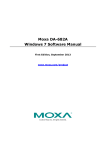
Enhanced Write Filter (EWF) provides a means for protecting a volume from unauthorized writes by making the
main OS drive a write-protected volume, effectively making the system a read-only system for most users. This
gives much stronger protection against malicious computer code like trojans, worms, and viruses.
Enhanced Write Filter (EWF) allows Windows 7 users to protect their all information on their storage drive
from permanent changes of any sort, at the lowest level of hardware protection available: the bit level. EWF
allows the operating system (OS) to boot from the hard disk, but protects the system by creating a virtual file
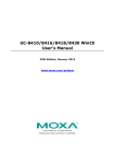
system called an overlay. All writes to an EWF-protected volume (the hard disk, in Fig. 1) are only recorded
on this virtual overlay (the EWF Volume, in Fig. 1), which is stored independently in random access memory
(RAM). Because EWF does not write data directly to the hard disk but instead only records system writes to this
virtual RAM overlay, any data that is “written” during system operation will disappear upon the next re-boot.
This approach allows the system to operate as if it is writeable when in reality all OS and user-space file
systems are stored in a permanent, read-only state. If desired, the data written to the overlay may be
committed to the protected volume, but this requires additional setup and permissions that can only be granted
by the administrator. Refer to the following figure (from Microsoft) for an overview of the EWF structure.
For more details about EWF configuration and usage, you may:
•
Visit Microsoft’s EWF Volume Configuration help pages.
•
Visit Microsoft’s EWF overview on the official Microsoft EWF help pages.
•
Visit Microsoft’s detailed description of EWF modes on the EWF help pages.
•
Visit Microsoft’s detailed description of the EWF API.
For the EWF commands, refer to the MSDN web site:
http://msdn.microsoft.com/en-us/library/ms940853%28v=winembedded.5%29.aspx
Enabling Enhanced Write Filter
Follow these steps to enable the Enhanced Write Filter.
1.
To open the EWF control dialog, open the
system tray (located in the lower right
corner of the desktop) and right-click on
the padlock icon.
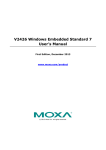
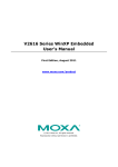
2.
Select the volume you wish to enable
write-protection on by selecting the
partition (A) in the Volume Information
dialog, and then pressing the Configure
button (B) in the lower left section of the
dialog.
A
B
3.
After opening the configuration dialog,
choose to enable Enhanced Write Filter on
your drive volume by selecting Enable
from the Pending command dialog and
then clicking OK to close the dialog.
4.
Reboot the system.
5.
After logging in to the desktop environment,
open the system tray (located in the lower
right corner of the desktop) and check to
verify that the padlock icon now shows the
drive volume is locked down with EWF.
Committing Data and/or Disabling EWF
When EWF is enabled on a drive users will need to go through a special process to write any data to the hard
drive. Writing data to the drive in this situation is called a Commit, and users must be given administrator
privileges to be able to do so.
1.
Open the EWF control dialog by
right-clicking on the padlocked drive in the
system tray (located in the lower right
corner of the desktop).
2.
Once the EWF control dialog is open, select
the drive you wish to operate and click on
the Configure button in the lower left
corner. This will open the EWF
Configuration page.
3.
Once the EWF control dialog is open, select
the drive you wish to operate from the upper
window of the dialog, and then click on the
Pending Command drop-down menu just
beneath. Here, you will see four choices:
No Command
Disable: This disables EWF on the
selected drive. Be aware that the system
will automatically reboot if you select this
command.
Commit: This writes all current changes
to the system data to the hard drive; any
changes that have been made to the
system settings.
Commit and Disable Live: This writes
all current data and changes to the
system, and also turns off EWF on the
selected drive (so that all future data and
system changes will also be committed to
the drive, as well). Selecting this option
will NOT automatically reboot your
system.
For more detailed descriptions of these commands, please refer to the Microsoft website shown below:
http://msdn.microsoft.com/en-us/library/ff794092(v=winembedded.60).aspx
File-Based Write Filter
Overview
This section describes how to use the File-Based Writer Filter (FBWF). Please note that when Enhance Writer
Filter is enabled, the File-Based Writer Filter function will not work.
According to Microsoft:
File-Based Write Filter (FBWF) allows the Windows Embedded platform to maintain the
appearance of read and write access on write-sensitive or read-only storage. FBWF
makes read and write access transparent to applications.
Writing to storage media may be undesirable or impossible in embedded devices. FBWF
redirects all writes targeted for protected volumes to a RAM cache called an overlay. Used
in this context, an overlay is similar to a transparency overlay on an overhead projector.
Any change made to the overlay affects the picture as seen in the aggregate, but if the
overlay is removed, the underlying picture remains unchanged.
FBWF provides the advanced feature than EWF to let user specify the directory to write the data to disk drive
directly, in our default setting, the default directory is under c:\temp, which means you can read/write the data
into disk without commit action.
Configuring File-Based Write Filter
Follow these steps to enable the Enhanced Write Filter. Keep in mind that, while FBWF and EWF may both be
enabled on the same machine; FBWF can not protect a volume also protected by EWF. Similarly, EWF can not
protect a volume also protected by FBWF.
1.
To open the FBWF overview window, open
the system tray (located in the lower right
corner of the desktop) and right-click on
the padlock icon.
NOTE: When disabled, the icons for EWF
and FBWF are identical. After the dialog
opens b sure to verify you have opened the
correct window.
2.
When the overview window opens, you will
receive a quick report on the current FBWF
configuration. The diagram at right shows
what it will look like before it is enabled. To
continue with the setup, click on the
Configure button just before the report
window.
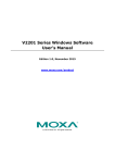
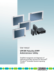
3.
The FBWF configuration window is
considerably more complicated than the
EWF setup. To enable FBWF protection on
your main storage drive, you will need to
A
B
enable the filter by ticking Filter state
enabled (A) and Cache pre-allocation
enabled (B). Next, select the drive you
C
want to protect from the Volume
Configuration menu (C) and then click on
the Protect button. Finally, click on Apply
D
(E), or OK to set the FBWF configuration.
Cache compression may be used on the
overlay cache to minimize the amount of
memory used. Cache compression
decreases performance when accessing
E
protected volumes, and cannot be used
with pre-allocation.
Cache pre-allocation sets the memory space available for the overlay cache at the system’s start,
instead of adjusting it as needed. It cannot be used with cache compression.
The cache threshold specifies the amount of memory that can be used by the write filter for the overlay
cache. The default value and size limits for the overlay cache vary by operating system.
4.
Reboot the system.
5.
Once again, open the system tray (located in
the lower right corner of the desktop) and
check to verify that the padlock icon now
shows you have enabled FBWF. The icon
should have changed to become a padlock
displaying the number 10, as shown in the
figure at right.
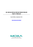
Excluding Files from FBWF Protection
1.
Click on the FBWF icon (in the desktop
systray) to open the Overview dialog. Click
on Configure to switch to the configuration
interface.
2.
Click on the Exclusion List tab. Make sure
the correct drive volume is shown in the
dropdown menu labeled Volume Name; if
not, select the correct volume from the
dropdown menu.
Next, you must select the file path you wish
to exclude from FBWF protection; this wll
allow the drive to write to the selected files
and directories, so be careful. You may
indicate an entire section of the file tree by
selecting an entire file path, or you may
select individual files.
To select individual files, click on the Browse
button (marked with ellipses, in the lower
right corner, as shown at right). This will
open a Windows Explorer interface.
3.
Navigate to the file(s) you wish to exclude
from FBWF protection, select the file, and
then click Open to enter the path into the
exclusion dialog; this will exit the Windows
Explorer interface and return you to the
Exclusion List interface shown in step 2.
4.
You should now see the file or file path you
selected for exclusion listed in the Add
Path dialog, at the bottom of the
Exclusion List tab. Click the add button
(+) to add the path or file to the exclusion
list.
5.
After adding a file or path to the exclusion
list, you should see it listed in the Path
window. If the file does not appear, then it
has not yet been added.
13. Reboot the system for the changes to take effect.
Managing Temporary Files Cached in the Overlay
1.
In the Cached Content tab you will see all
the files currently cached in the RAM overlay,
with three commands you may execute:
Commit will save a file from the cache to
permanent storage, deleting the file from the
overlay and overwriting the original.
Restore will return the file to its original
state, removing it from the overlay cache and
discarding the changes that caused it to be
added to the cache.
Add to exclusion list adds the file to the
exclusion list after the next restart. Because
this makes the file read-only, if it is executed
on the wrong file it may render your system
or particular applications inoperable.
2.
The most common usage of the Cache
Content filter will likely be to permanently
write content to the hard drive. To do this,
select the file you wish to write to
permanent memory and click on the
commit button. This will delete the file from
the cached overlay and replace the current
file in permanent storage with the modified
cache file.
Users should understand that if they commit
a configuration or application file, they will
be permanently altering the setup and/or
performance of the application or system.
To get more details about FBWF configuration and usage, you may consult the Micrsoft help file that comes with
your computer, or:
Go to Microsoft’s FBWF Installation and Configuration help pages.
Go to Microsoft’s FBWF overview on the official Microsoft FBWF help pages.
Go to Microsoft’s detailed description of FBWF features on the FBWF help pages.
Go to Microsoft’s detailed description of the FBWF API.
4
4.
Customizable Sample Code
This chapter uses sample code to show how scripting may be used to add customized capabilities to the DA-683
computing platform.
The following topics are covered in this chapter:
Sample Code for Customizing the DA-683
The DIO Control Walkthrough
The LED Control Walkthrough
Watchdog Control Code
The Watchdog Control Code Walkthrough
Sample Code for Customizing the DA-683
The DA-683 computer comes with several pieces of sample code that may be used to customize its behavior for
LED notifications, DIO Control, or to initiate emergency reboots when critical system applications come to a
halt.
The DIO Control Walkthrough
The DA-683 is designed with 4 digital inputs and 4 digital outputs that integrators and system administrators
may customize for their needs. The source code for controlling digital I/O behavior is located in the folder
<Software DVD>\examples\Example\C++\DIO\, while the compiled executable DIO.exe is located
under <Software DVD>\examples\Release. You can follow the steps below to test the digital I/O control
script, or you may freely modify the control script to create customized patterns that are associated with
specific system events. To review the digital I/O control code, see the section Sample Code for Digital I/O
Control in Appendix A of this manual.
1.
Create the c:\programs\examples folder and copy DIO.exe into that folder. Run DIO.exe.
2.
You will be presented with a menu of three choices; first, select 1 to display the DIO’s current status.
3.
In the screenshot below, the user has selected 1.
4.
You may now run DIO.exe again, but this time select 2. At the next prompt, enter the ID number (0 to 3)
of a DIO to activate, and when prompted enter either 1 (to turn it on), or 0 (to turn it off).
The LED Control Walkthrough
The DA-683 is designed with 8 programmable LEDs that integrators and system administrators may customize
for their notification needs. The source code for controlling LED behavior is located in the folder <Software
DVD>\examples\Example\C++\LED\, while the compiled executable LED.exe is located under <Software
DVD>\examples\Release. You can follow the steps below to test the LED control script, or you may freely
modify the control script to create customized patterns that are associated with specific system events. To
review the LED control code, see the section Sample Code for LED Control in Appendix A of this manual.
5.
Create the c:\programs\examples folder and copy LED.exe into that folder. Run LED.exe.
6.
You will be presented with a menu of three choices; first, select 1 to display the LED’s current status.
7.
In the screenshot below, the user has selected 1 and is viewing the current status of all LEDs. The value
0 shown next to each entry indicates that all of the LEDs are currently turned off. Visually verify this by
examining the DA-683’s front panel.
8.
You may now run LED.exe again, but this time select 2. At the next prompt, enter the ID number (0 to 7)
of an LED to activate it. When prompted enter either 1 (to turn it on), or 0 (to turn it off). The LEDs on the
main DA-683 panel correspond to 0 through 3; 4 and 5 correspond to those on the first module; and 6 and
7 to those on the second.
Watchdog Control Code
The code for controlling the watchdog/COP timer is the simplest and least-customizable of the included sample
scripts. The code itself is provided on the software DVD, under \examples\Example\C++\WatchDog\,
and the executable file Watchdog.exe is on the software DVD\examples\Release. This sample code may
be modified to integrate the watchdog timer with specific applications
Using this code, any program may be set up so that the watchdog timer will provide a last-line failsafe against
application crashes. For instance, the DA-683 may be set up so that whenever a mission-critical application
fails the watchdog timer will send a message to a system administrator and then initiate an automatic reboot.
To test the watchdog executable, follow the steps below.
The Watchdog Control Code Walkthrough
1.
If you haven’t yet, create the folder c:\programs\examples, then copy over Watchdog.exe and run
the script.
2.
To keep the system from rebooting, press Enter at least once every 10 seconds, or the system will reboot
automatically.
3.
To stop the watchdog, press q to exit the program.
5
5.
System Recovery
The DA-683 ready-to-run embedded computers come with the Windows Embedded Standard 7 platform. This
chapter describes the recovery process in the event of system instability.
The following topics are covered in this chapter:
Overview: Setting Up the Recovery Environment
Step 1: Prepare the USB drive
Step 2: Setting the BIOS to Boot via USB
Step 3 (opt.): Create a Custom System Image
Step 4: Reset BIOS to Original State
Step 5: Perform a Test Restoration
Overview: Setting Up the Recovery Environment
The recovery procedure itself requires only a DA-683 computer, a 4 GB (min.) USB drive, and a copy of the
recovery suite to set up the recovery environment. The recovery procedure itself requires only a DA-683
computer and a bootable USB drive.
The following procedure describes the basic process of setting up the system recovery environment.
1. First, the recovery programs and system image file will be copied over to the USB drive, and the drive will
be set up to provide a system boot process by copying an ISO image of the boot environment to the USB.
2. The system will be re-booted, and BIOS will be manually configured to boot the system from the USB port.
3. An image of the current software system will be created on the USB drive for the recovery environment to
use when restoring the system.
4. The system will be re-booted again, and the BIOS returned to its original state.
Step 1: Prepare the USB drive
1. Load the software DVD that came with your DA-683 computer and execute tuxboot-windows-23.exe
from the software DVD\recovery\ folder, select Pre-Downloaded, and click the button marked with an
ellipsis (…) to browse the file system and find the location of the boot environment’s ISO image.
2. Navigate to\recovery\on the software DVD and select the boot environment’s ISO image.
3. Set the device Type (lower left-hand corner) as USB Drive, then set the Drive dialog to the letter under
which the USB is currently mounted.
4. Click OK, and the boot environment and bootloader will be copied to your USB drive.
5. Because of the file system naming conventions used, for any given computer only a single recovery image
may be used on any given USB drive. Consequently, at this point, users need to make a decision about
which sort of system recovery is preferred:
A.
a basic recovery of the root OS, or
B.
a recovery image of the fully configured OS, with all user-installed software applications and
scripts.
A. To configure the recovery environment to boot into a fully configured system, click Reboot Now to
close the installation environment and restart the computer. You should then proceed to the next
section, Step 2: Setting the BIOS to Boot via USB and continue the installation of the recovery
environment by following the instructions at Step 3 (opt.): Creating a Custom System Image.
B. To configure the recovery environment to boot into a clean OS image with no applications, you should
instead click Exit here to complete the installation and return to the OS. From within the desktop
environment, you should manually copy the directory containing the base OS from the software DVD
over to the USB drive. To do this, copy #:\<SoftwareDVD>\recovery\os_image over to the
partition image directory, F:\home\partimag\. At this point, Step 1 has been completed, and you
should proceed to Step 2: Setting the BIOS to Boot via USB.
ATTENTION
Because of the peculiarities of the file tree naming, it is not possible to include both the base OS image and a
fully configured system image on the same USB stick. If you wish to configure both, then two USB drives must
be used, each configured according to the two different alternatives offered here.
Step 2: Setting the BIOS to Boot via USB
At this stage, reset the BIOS so that the system boots directly from the USB. This must be done before the rest
of the system recovery environment can be configured
1. Turn on the computer, during the POST process, press F2 until you hear a long beep. You should then enter
the BIOS setup menu.
2. Use the arrow keys to navigate to the Boot tab, and then press Enter.
3. Select Boot Type Order in Legacy to open the dialog that will allow you to set the boot priority for the
system drives.
4. Use the arrow keys to highlight USB and then press the plus key (+) to move it to the first position, or
select the other options above it and use the dash key(–) to move them down.
5. Press F10 and then press Enter to save and exit the BIOS configuration interface. This should initiate the
next reboot, during which your system should now boot from the USB drive.
Step 3 (opt.): Create a Custom System Image
The instructions which follow are only to be used if you decided in of this process to create a full copy of an
already-configured system. If you have not yet installed any software on your system, then return to
section 5b of Step 1: Preparing the USB Drive and follow the instructions to create a clean OS image.
Using this procedure, you will save to the USB drive a copy of the entire system as it is currently configured
to be used as a full system recovery image should the system crash. All files under F:\home\partimag\
will be overwritten. Additionally, you should have already changed the BIOS settings to make the USB drive
the first boot priority. If you have not yet reset the boot priority, first return to Step 2: Setting the BIOS to
Boot via USB, just above, and follow the directions there.
1. Once the system has launched and the DA-683 has booted the recovery environment from the USB drive,
navigate to the entry ClonezillaLive Save Disk, and select it by pressing Enter. This will take you into the
recovery image creation environment, allowing you to copy your full system setup to the USB drive.
2. The DA-683 will now boot into the image creation environment. Wait for the boot process to finish.
3. Once the image creation environment has completed booting up, you will be given a warning and asked if
you wish to continue. Keep in mind that if you create the recovery image, then any residual files
currently copied to the /home/partimag directory will be deleted. If there are any files remaining in
the USB partition image directory and you wish to save them, you must exit the recovery environment
and copy these files to another disk. If you wish to continue with the image creation, press Y (case
insensitive) to continue (screenshot at the top of the next page).
WARNING
The same filename is used for all recovery images, whether for the full system backup or for the clean OS image
installation. This means that currently, it is impossible to have more than one system image per USB drive.
4. At this point, the recovery environment will copy of the entire hard drive to your USB drive. This will likely
take several minutes, and perhaps as long as half an hour. Do not remove the USB drive during this time;
wait patiently for the process to finish. Depending on the speed of your USB drive, this may be a good time
to get a cup of coffee, or take a nap.
5. At this point you may choose to power down the computer (press 0), reboot (press 1), enter a console
terminal (access a console TTY -- press 2), or re-initiate the entire procedure (press 3). Do not remove
the USB drive until you have rebooted or powered down the system.
6. Once you have powered down the system and removed the USB drive, you have finished configuring the
recovery environment. The USB drive should be clearly labeled and stored in a safe place. You may now
continue to the next section, where you will return the BIOS to its original state (Step 4) and test the
recovery procedure for successful configuration (Step 5).
Step 4: Reset BIOS to Original State
Now you will need to return the boot priority to its original configuration so that the system will boot from the
original disk. This is done for two reasons; the first is security, so that the machine may not be rebooted from
unauthorized USB drives. The second, however, is functional: currently, if the DA-683 is set to boot from the
USB drive, then the DA-683 will hang any time a USB data drive (i.e.: non-bootable image) is inserted
in the machine at boot time. The DA-683 does not currently have the capacity to distinguish between simple
USB data drives and boot-capable OS drives.
1. Reboot the system, and press F2 to enter the BIOS setup menu.
2. Select Hard Disk and shift it to the top boot priority by using the + key, then press Enter. Make sure the
hard disk has first boot priority.
3. Press F10 and then press Enter to save and exit the BIOS settings dialog.
Step 5: Perform a Test Restoration
Connect the USB drive to any of the DA-683’s USB ports and then reboot the computer. The system will boot
from the USB into the Clonezilla boot loader.
1. Select ClonezillaLive Restore Disk to boot into the system restoration environment.
2. Wait for the boot process to finish.
3. At this point, the system will remind you that you are about to overwrite your entire operating system with
a new drive image, and ask you if you want to continue. When prompted, enter Y (case insensitive) from
the keyboard to start the system restoration process. Any other letter or Ctrl-C will cancel and exit
Clonezilla.
4. The system will give you another warning that you are about to overwrite your hard drive, and erase all data
on the partition listed (sda1, in the example below). If you wish to continue, enter Y (case insensitive).
5. Wait for the process to finish.
6. At this point, complete the restoration by selecting (0) Power off. The computer will shut down; however,
if the Power Switch remains inserted in the front panel of the computer and is left in the ON position, then
the system will fail to shutdown and will immediately initiate a soft reboot, instead. To avoid this, use the
switch to cut power to the computer immediately following the shutdown, or simply remove the power
switch from the front panel and then use the console to shut down the computer by pressing 0.
7. After the computer has powered down, remove the USB drive and store it in a safe place.
A
A.
Sample Code for DA-683 Customization
This appendix gives you a hard copy of the sample code included with the DA-683. These short programs are
intended to be used either as standalone scripts, or to be included in scripts created to build custom features
for end users. You can find the sample code in C# and C++ from DVD\examples\Example\ folder.
The following topics are covered in this appendix:
The DIO Control Sample Code
The LED Control Sample Code
The Watchdog Control Sample Code
Sample Code for Digital I/O Control
Below we reproduce the LED control code. This is a simple function that users may freely modify to suit their
needs.
/* Copyright (C) MOXA Inc. All rights reserved.
This software is distributed under the terms of the
MOXA License. See the file COPYING-MOXA for details.
*/
#include "stdafx.h"
#include <windows.h>
#include "..\\Include\\mxdev.h"
#define DI_PORT_NUMBER 4
#define DO_PORT_NUMBER 4
int _tmain(intargc, _TCHAR* argv[])
{
HANDLE hDioDev;
intport_no;
int data;
intnData = 0;
intnRet = 0;
int port = 0;
int mode = 0;
int n = 0;
TCHAR sin;
TCHAR smode;
_tprintf(_T("DIO Test Program\r\n"));
_tprintf(_T("\t (0) Exit Program\r\n"));
_tprintf(_T("\t (1) Display DO & DI\r\n"));
_tprintf(_T("\t (2) Set DO value\r\n"));
sin = _gettchar();
n = _tstoi(&sin);
do
{
switch (n)
{
// if char == '1', display the DI/DO status
case 1:
// Open device
hDioDev = mxdgio_open();
for (inti = 0; i< DI_PORT_NUMBER; i++)
{
// Get digital input
port_no = i;
nData = mxdgio_get_input_signal( hDioDev, port_no);
_tprintf(_T("DI[%d] = %d\r\n"), port_no, nData);
}
for (inti = 0; i< DO_PORT_NUMBER; i++)
{
// Get digital input
port_no = i;
nData = mxdgio_get_output_signal( hDioDev, port_no);
_tprintf(_T("DO[%d] = %d\r\n"), port_no, nData);
}
// Close device
mxgpio_close(hDioDev);
break;
// if char == '2', Set the DO
case 2:
// Get Port Number
_gettchar();
_tprintf(_T("Input the Port Number (0 ~ %d) = \r\n"),
DO_PORT_NUMBER-1);
smode = _gettchar();
port_no = _tstoi(&smode);
// Get Value
_gettchar();
_tprintf(_T("Input the value (0 or 1) = "));
smode = _gettchar();
data = _tstoi(&smode);
// Open device
hDioDev = mxgpio_open();
// Set DO
nRet = mxdgio_set_output_signal( hDioDev, port_no, data);
if ( nRet == -1 )
{
_tprintf(_T("Set DO signal fail!\r\n"));
}
else
{
_tprintf(_T("Set DO signal success!\r\n"));
}
// Close device
mxgpio_close(hDioDev);
break;
}
_gettchar();
sin = _gettchar();
n = _tstoi(&sin);
} while (n != 0);
}
return 0;
Sample Code for LED Control
Below we reproduce the LED control code. This is a simple function that users may freely modify to suit their
needs.
/* Copyright (C) MOXA Inc. All rights reserved.
This software is distributed under the terms of the
*/
MOXA License. See the file COPYING-MOXA for details.
#include "stdafx.h"
#include <windows.h>
#include "..\\Include\\mxdev.h"
#define LED_PORT_NUMBER 8
int _tmain(intargc, _TCHAR* argv[])
{
HANDLE hLedDev;
intport_no;
int data;
intnLED = 0;
intnRet = 0;
int port = 0;
int mode = 0;
int n = 0;
TCHAR sin;
TCHAR smode;
_tprintf(_T("LED Test Program\r\n"));
_tprintf(_T("\t (0) Exit Program\r\n"));
_tprintf(_T("\t (1) Display LED\r\n"));
_tprintf(_T("\t (2) Set LED value\r\n"));
sin = _gettchar();
n = _tstoi(&sin);
do
{
switch (n)
{
// if char == '1', display the LED output status
case 1:
// Open device
hLedDev = mxgpio_open();
for (inti = 0; i< LED_PORT_NUMBER; i++)
{
// Get digital input
port_no = i;
nLED = mxgpio_get_data( hLedDev, port_no);
_tprintf(_T("LED[%d] = %d\r\n"), port_no, nLED);
}
// Close device
mxgpio_close(hLedDev);
break;
// if char == '2', Set the LED output
case 2:
// Get Port Number
_gettchar();
_tprintf(_T("Input the Port Number (0 ~ %d) = \r\n"),
LED_PORT_NUMBER-1);
smode = _gettchar();
port_no = _tstoi(&smode);
// Get Value
_gettchar();
_tprintf(_T("Input the value (0 or 1) = "));
smode = _gettchar();
data = _tstoi(&smode);
// Open device
hLedDev = mxgpio_open();
// Set LED
nRet = mxgpio_set_data( hLedDev, port_no, data);
if ( nRet == -1 )
{
_tprintf(_T("Set led signal fail!\r\n"));
}
else
{
_tprintf(_T("Set led signal success!\r\n"));
}
// Close device
mxgpio_close(hLedDev);
break;
}
_gettchar();
sin = _gettchar();
n = _tstoi(&sin);
} while (n != 0);
}
return 0;
The Watchdog Control Sample Code
/* Copyright (C) MOXA Inc. All rights reserved.
This software is distributed under the terms of the
MOXA License. See the file COPYING-MOXA for details.
*/
#include "stdafx.h"
#include <windows.h>
#include "..\\Include\\mxdev.h"
int _tmain(intargc, _TCHAR* argv[])
{
PVOID fd; // Handle to device, obtain from mxwdg_open
ULONG time;
// starts watchdog timer
time = 10;
fd = mxwdg_open(time);
while ( TRUE )
{
_tprintf( _T("Press \"ENTER\" in 10 seconds\n, 'q' to exit"));
TCHAR ch = _gettchar();
if ( ch == (TCHAR)'q' )
{
break;
}
// refresh watchdog timer
mxwdg_refresh(fd);
}
// stops watchdog timer
mxwdg_close(fd);
return 0;
}