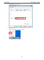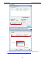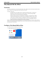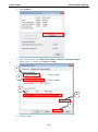
1
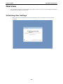
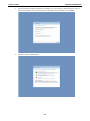
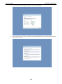
V2416 Windows Embedded Standard 7 User’s Manual First Edition, March 2014 www.moxa.com/product © 2014 Moxa Inc. All rights reserved. V2416 Windows Embedded Standard 7 User’s Manual The software described in this manual is furnished under a license agreement and may be used only in accordance with the terms of that agreement. Copyright Notice © 2014 Moxa Inc. All rights reserved. Trademarks The MOXA logo is a registered trademark of Moxa Inc. All other trademarks or registered marks in this manual belong to their respective manufacturers. Disclaimer Information in this document is subject to change without notice and does not represent a commitment on the part of Moxa. Moxa provides this document as is, without warranty of any kind, either expressed or implied, including, but not limited to, its particular purpose. Moxa reserves the right to make improvements and/or changes to this manual, or to the products and/or the programs described in this manual, at any time. Information provided in this manual is intended to be accurate and reliable. However, Moxa assumes no responsibility for its use, or for any infringements on the rights of third parties that may result from its use. This product might include unintentional technical or typographical errors. Changes are periodically made to the information herein to correct such errors, and these changes are incorporated into new editions of the publication. Technical Support Contact Information www.moxa.com/support Moxa Americas Moxa China (Shanghai office) Toll-free: 1-888-669-2872 Toll-free: 800-820-5036 Tel: +1-714-528-6777 Tel: +86-21-5258-9955 Fax: +1-714-528-6778 Fax: +86-21-5258-5505 Moxa Europe Moxa Asia-Pacific Tel: +49-89-3 70 03 99-0 Tel: +886-2-8919-1230 Fax: +49-89-3 70 03 99-99 Fax: +886-2-8919-1231 Moxa India Tel: +91-80-4172-9088 Fax: +91-80-4132-1045 Table of Contents 1. Introduction ...................................................................................................................................... 1-1 Software Components ......................................................................................................................... 1-2 2. System Initialization ......................................................................................................................... 2-1 Overview ........................................................................................................................................... 2-2 Initializing User Settings .............................................................................................................. 2-2 3. Enabling Embedded Filters ................................................................................................................ 3-1 Enhanced Write Filter .......................................................................................................................... 3-2 Overview .................................................................................................................................... 3-2 Enabling Enhanced Write Filter ...................................................................................................... 3-3 File-Based Write Filter ......................................................................................................................... 3-6 Overview .................................................................................................................................... 3-6 Configure File-Based Write Filter ................................................................................................... 3-6 4. Moxa Software Packages................................................................................................................... 4-1 Installing mxlibrary_setup Package ....................................................................................................... 4-2 Moxa Hot Stop (mxhtsp) Function Package for Disk Drive ........................................................................ 4-3 Overview .................................................................................................................................... 4-3 Installing mxhtsp Function Package ............................................................................................... 4-4 Configuring Hot Swap Functions ........................................................................................................... 4-6 Starting Hot Swap Applications ..................................................................................................... 4-6 Configuring Hot Swap Application Settings...................................................................................... 4-7 Executing Monitor Function via Scripts ........................................................................................... 4-8 5. Examples........................................................................................................................................... 5-1 Watchdog .......................................................................................................................................... 5-2 Enabling Watchdog Function ......................................................................................................... 5-2 6. System Recovery ............................................................................................................................... 6-1 Overview: Setting Up the Recovery Environment .................................................................................... 6-2 Step 1: Prepare the USB drive .............................................................................................................. 6-2 Step 2: Setting the BIOS to Boot via USB .............................................................................................. 6-4 Step 3 (opt.): Create a Custom System Image ....................................................................................... 6-4 Step 4: Reset BIOS to Original State ..................................................................................................... 6-7 Step 5: Perform a Test Restoration ....................................................................................................... 6-8 1 1. Introduction Thank you for using Moxa’s V2416 series of x86 ready-to-run embedded computers. The Windows Embedded Standard 7 operating system provides a simple and familiar development environment for on-board train applications. Software Components V2416 / W7E Introduction Software Components The following Windows Embedded Standard 7 software components are pre-installed on V2416 computers. Core OS: • 32-bit support • Remote Client • Remote Procedure Call Applications and Services Development: • .Net Framework 3.5 • Remote Desktop Protocol 7.1 • COM OLE Application Support • COM+ Application Support • MSMQ Internet Services: • Internet Explorer 8.0 • IIS 7.0 File Systems and Data Store: • Windows Data Access Components • Windows Backup and Restore Diagnostics: • Common Diagnostic Tools • Problem Reports and Solutions Fonts: Chinese (Trad. and Simp.), Japanese, Korean, Western, Middle Eastern, South East Asian, and South Asian Fonts Graphics and Multimedia: • MPEG DTV-DVD Audio Decoder (MPEG-2, AAC) • MPEG Layer-3 Audio Codecs(MP3) • MPEG4 Decoders • Windows Media Video VC-1 (WMV) Codecs • DirectX and Windows Device Experience • Windows Media Player 12 International: • IME Simplified Chinese Support • IME Traditional Chinese Support Management: • Group Policy Management • Windows Management Instrument (WMI) • Windows Update Networking: • Extensible Authentication Protocol (EAP) • Internet Authentication Service • Telnet Server • Bluetooth • Domain Services • Network Access Protection • Network and Sharing Center • Quality of Service • Remote Access Service (RAS) • Telephony API Client • Windows Firewall • Wireless Networking 1-2 V2416 / W7E Introduction Security: • Credential Roaming Service • Credentials and Certificate Management • Windows Authorization Manager (AZMAN) • Windows Security Center • Active Directory Rights Management • Security Base • Encrypted File System (EFS) Embedded Features: • Enhanced Write Filter (EWF) • File-Based Write Filter (FBWF) • Message Box Default Reply • Registry Filter • WSDAPI for .NET Embedded Self-Health Diagnostic Software: SNMP-based remote scripting layer for monitoring, reporting, and control 1-3 2 2. System Initialization In this chapter, we describe how to initialize the system settings on a V2416 computer when you boot up the computer for the first time. The following topics are covered in this chapter: Overview Initializing User Settings V2416 / W7E System Initialization Overview Like most laptop computer, you need to type a user name to create your user account to enable the embedded computer to work, follow the steps below: Initializing User Settings 1. When you boot the embedded computer for the first time, you need to enter a user name for this computer. 2-2 V2416 / W7E 2. System Initialization Type the password, retype the password. In addition, you may also type a password hint in case you forget your password. If you do not want to set the password, leave it blank and click Next. 3. Select the windows update option. 2-3 V2416 / W7E System Initialization 4. Select the time zone and daylight saving time option and click Next. 5. Select computer’s current location. Windows will automatically apply the correct network settings based o the network’s location. 2-4 V2416 / W7E 6. System Initialization Now you can start to use V2416 embedded computer. 2-5 3 3. Enabling Embedded Filters This chapter describes how to operate the embedded enabling features on the V2416 computers. The following topics are covered in this chapter: Enhanced Write Filter Overview Enabling Enhanced Write Filter File-Based Write Filter Overview Configure File-Based Write Filter V2416 / W7E Moxa Software Package Enhanced Write Filter Overview Enhanced Write Filter (EWF) provides a means for protecting a volume from writes. This allows the operating system (OS) to boot from write-protected hard disks. All writes to an EWF-protected volume. (The Hard Disk in the figure below) are redirected to an overlay(EWF Volume in the figure below). Because EWF does not write data to hard disk directly, so it can protect the hard disk from sudden power loose. These writes are cached in the overlay and made available as part of the volume. This gives the appearance that the volume is writeable. The overlay is an independent storage location which exists in random access memory (RAM). If desired, the data stored in the overlay may be committed to the protected volume. Refer to the following figure for the overview of the EWF structure. To get more details about EWF configuration and usage, you may: • Visit Microsoft’s EWF Volume Configuration help pages. • Visit Microsoft’s EWF overview on the official Microsoft EWF help pages. • Visit Microsoft’s detailed description of EWF modes on the EWF help pages. • Visit Microsoft’s detailed description of the EWF API. For the EWF commands, refer to the MSDN web site: http://msdn.microsoft.com/en-us/library/ms940853%28v=winembedded.5%29.aspx 3-2 V2416 / W7E Moxa Software Package Enabling Enhanced Write Filter Follow these steps to enable the Enhanced Write Filter. 1. First open right-click the lock icon in the left side. 2. Select volume in Volume Information and then select Configure. 1 2 3-3 V2416 / W7E Moxa Software Package 3. Select Enable in Pending Command. 4. Reboot the system. 5. Check if the icon has been changed to locked status. 3-4 V2416 / W7E Moxa Software Package 6. Select Configure. 7. Select volume and select the Pending Command for your need. For the detailed descriptions for these commands, please refer to the Microsoft website shown below: http://msdn.microsoft.com/en-us/library/ff794092(v=winembedded.60).aspx 3-5 V2416 / W7E Moxa Software Package File-Based Write Filter Overview This section describes how to use the File-Based Writer Filter (FBWF). Please note that when Enhance Writer Filter is enabled, the File-Based Writer Filter function will not work. According to Microsoft: File-Based Write Filter (FBWF) allows the Windows Embedded platform to maintain the appearance of read and write access on write-sensitive or read-only storage. FBWF makes read and write access transparent to applications. Writing to storage media may be undesirable or impossible in embedded devices. FBWF redirects all writes targeted for protected volumes to a RAM cache called an overlay. Used in this context, an overlay is similar to a transparency overlay on an overhead projector. Any change made to the overlay affects the picture as seen in the aggregate, but if the overlay is removed, the underlying picture remains unchanged. FBWF provides the advanced feature than EWF to let user specify the directory to write the data to disk drive directly, in our default setting, the default directory is under c:\temp, which means you can read/write the data into disk without commit action. Configure File-Based Write Filter To enable file-based write filtering, do the following: 1. Right-click the lock icon on the right side. 3-6 V2416 / W7E 2. 3. Moxa Software Package Select Configure. In the configuration tab, check Filter state enabled and Cache pre-allocation enabled. And then select C:, and then select Protect and Apply. 1 2 3 4 5 4. Reboot the system. 3-7 V2416 / W7E 5. Right-click the icon. 6. Click Configure. Moxa Software Package 3-8 V2416 / W7E Moxa Software Package 7. Change to Exclusion List and select browse button. 8. Select the file to exclude the protection. 3-9 V2416 / W7E 9. Moxa Software Package Click + button. 10. Check if the file path has been added. 3-10 V2416 / W7E Moxa Software Package 11. Change to Cache Content tab. 12. Select the file to you want to save to physical disk and select commit. 1 2 13. Reboot system to take effect. 3-11 V2416 / W7E Moxa Software Package To get more details about EWF configuration and usage, you may: Go to Microsoft’s FBWF Installation and Configuration help pages. Go to Microsoft’s FBWF overview on the official Microsoft EWF help pages. Go to Microsoft’s detailed description of FBWF features on the EWF help pages. Go to Microsoft’s detailed description of the FBWF API. 3-12 4 4. Moxa Software Packages This chapter describes the software package for users to easily control and monitor the V2416 computers. The following topics are covered in this chapter: Installing mxlibrary_setup Package Moxa Hot Stop (mxhtsp) Function Package for Disk Drive Configuring Hot Swap Functions Starting Hot Swap Applications Configuring Hot Swap Application Settings Executing Monitor Function via Scripts V2416 / W7E Moxa Software Package Installing mxlibrary_setup Package Follow these steps to install mxlibrary_setup (Moxa Library) package. This library will be used when users want to use the examples such as DIO, Watchdog, and disk drive hot-swap function. 1. Double click mxlibrary_setup.msi under Utility folder in the software DVD\utility\1.mxlibrary\. 2. Click Next to start the installation. 3. Select the folder you want to install the package, or simply click Next to continue if you want to use the default folder. 4. Click Next to continue. 3-2 V2416 / W7E 5. Moxa Software Package Wait until the installation has completed. Click Close to finish. Moxa Hot Stop (mxhtsp) Function Package for Disk Drive Overview The V2416 supports two SATA expansion slots to install 2.5 inch HDD/SSD. This package provides the disk drive hot swap function for you to safely remove your disk drive. To enable the function, you must follow the steps as follows to install mxhtsp package. 3-3 V2416 / W7E Moxa Software Package Installing mxhtsp Function Package Follow these steps to install mxhtsp_setup (Moxa Hot Swap Function) package. 1. Double click mxhtsp_setup.msi under Utility folder under <software DVD>\utility\2.mxhtsp\. 2. Click Next to continue. 3. Select the folder you want to install the package, or simply click Next to continue if you want to use the default folder. 4. Click Next to continue. 3-4 V2416 / W7E Moxa Software Package 5. Click Close to continue. 6. Click Yes to reboot the system When finished, you can start configuring the hot swap functions. See the following section. 3-5 V2416 / W7E Moxa Software Package Configuring Hot Swap Functions When you finish installing the mxhtsp setup package, you can start configuring the hot swap functions. See the following sections. Starting Hot Swap Applications The Moxa Hot-Swap function will be automatically started when you boot up the V2416 computer. The monitoring function will start to monitor the removable disk drive. Two features are provided by the Hot Swap (mxhtspd) application: 1. Self-defined button action: The buttons are related to corresponding hard disk. When you press the X1 button on the SATA expansion module, the specific disk will be removed and then you can unplug the hard disk. 2. Self-defined disk usage action: When the disk usage is over the custom setting, the LEDs will be light up and blinking 3 times to notify the user. For configuring the custom setting, see Configuring Hot Swap Application Settings section. The Hot Swap (mxhtspd) application uses its default action to handle the above three actions. Besides, you can execute your own actions via scripts located under C:\Program Files\MOXA\mxhtsp\script. 3-6 V2416 / W7E Moxa Software Package Configuring Hot Swap Application Settings The default settings of disk volumes to monitor are disk “D” and disk “E”. If you want to change the setting, follow these steps to adjust the settings. 1. Right-click the mxhtspd icon at the bottom right of the screen and then selects Setting. 2. In the setting page, you can select or change the volume letter you want to monitor when you change the volume letter. Also you can select to check the partition usage by check on the Check Partition option. By default, the hot swap application removes the hard drive as default action when you push the X1 button on SATA expansion module, to configure self-defined function, you need to check on Execute Script option and then modify the script to define your own behavior. When you change the setting, remember to click OK to save the settings. Note: If you split the hard disk into various volumes, then you have to specify the first volume name in the setting dialog, or the disk removal action may not function well. In addition, if you check Execute Script and Check Partition, the script will be run (the X2 LED indicator will blink as the default action), and partition check will be performed. 3-7 V2416 / W7E Moxa Software Package Executing Monitor Function via Scripts Each script is correspond to specific action, for example, when you press the button X1 on the SATA expansion module 1, the “action_btnX1_pressed.vbs” is activated and the action defined in the script will be executed. The following shows the definition of the script: action_btnX1_press.vbs : This script is executed when button X1 on SATA expansion module 1 is pressed, the default action of this script is to remove the hard disk1. action_btnX2_press.vbs : This script is executed when button X1 on SATA expansion module 2 is pressed , the default action of this script is to remove the hard disk2. action_disk1_plugged.vbs : This script is executed when disk1 is plugged , the default action of this script is to light up and light off the led1 3 times. action_disk2_plugged.vbs : This script is executed when disk2 is plugged , the default action of this script is to light up and light off the led1 3 times. Checking the Log File The event of status or error will be logged into the log file in the directory C:\Program Files\MOXA\mxhtsp\log. Each log file is tagged with date, and the events are logged with date and time. 3-8 V2416 / W7E Moxa Software Package 3-9 5 5. Examples This chapter describes how to use various examples on the V2416 computers for different functions. The following topics are covered in this chapter: Watchdog Enabling Watchdog Function V2416 / W7E Examples Watchdog The V2416 computers provide example for users to enable the watchdog function. The Watchdog example is under <Software DVD>\examples\project\WatchDog\ and the executable file Watchdog.exe is under <Software DVD>\examples\V2416Release. You can follow the steps below to test the watchdog function with executable file. Enabling Watchdog Function 1. Create c:\programs\example folder and copy the Watchdog.exe into the folder. 2. Execute Watchdog.exe. 3. You will see the *pdwPortVal = 0x80 which means the watchdog function is enabled, and then you need to press Enter in every 10 seconds or the system will reboot. 4. To stop the watchdog function, press q to exit the program, and you will see the *pdwPortVal = 0xc0 which means the watchdog function is disabled. 5-2 6 6. System Recovery The V2416 ready-to-run embedded computers are a Windows Embedded Standard 7 platform. This chapter describes the recovery process in the event of system instability. The following topics are covered in this chapter: Overview: Setting Up the Recovery Environment Step 1: Prepare the USB drive Step 2: Setting the BIOS to Boot via USB Step 3 (opt.): Create a Custom System Image Step 4: Reset BIOS to Original State Step 5: Perform a Test Restoration V2416 / W7E System Recovery Overview: Setting Up the Recovery Environment A V2416 computer, a 4 GB (min.) USB drive, and a copy of the recovery suite are all required to set up the V2416’s system recovery environment. The recovery procedure itself requires only a V2416 computer and a bootable USB drive. The following procedure describes the basic process of setting up the system recovery environment. 1. First, the recovery programs and system image file will be copied over to the USB drive, and the drive will be set up to provide a system boot process by copying an ISO image of the boot environment to the USB. 2. The system will be re-booted, and BIOS will be manually configured to boot the system from the USB port. 3. An image of the current software system will be created on the USB drive, for the recovery environment to use when restoring the system. 4. The system will be re-booted again, and the BIOS returned to its original state. Step 1: Prepare the USB drive 1. Load the software DVD that came with your V2416 computer and execute tuxboot-windows-23.exe from the software DVD\recovery\V2416W7E folder, select Pre-Downloaded, and click the button marked with an ellipsis (…) to browse the file system and find the location of the boot environment’s ISO image. 2. Navigate to\recovery\on the software DVD and select the boot environment’s ISO image. 3. Set the device Type (lower left-hand corner) as USB Drive, then set the Drive dialog to the letter under which the USB is currently mounted. 6-2 V2416 / W7E System Recovery 4. Click OK, and the boot environment t and bootloader will be copied to your USB drive. 5. Because of the file system naming conventions used, for any given computer only a single recovery image may be used on any given USB drive. Consequently, at this point, users need to make a decision about which sort of system recovery is preferred: A. a basic recovery of the root OS, or B. a recovery image of the fully configured OS, with all user-installed software applications and scripts. a. To configure the recovery environment to boot into a fully configured system, users should click Reboot Now to close the installation environment and restart the computer. They should then proceed to the next section, Step 2: Setting the BIOS to Boot via USB and continue the installation of the recovery environment by continuing to Step 3 (opt.): Creating a Custom System Image. b. To configure the recovery environment to boot into a clean OS image with no applications, users should instead click Exit here to complete the installation and return to the OS. From within the desktop environment, the user should then manually copy the directory containing the base OS from the software DVD over to the USB drive. To do this, copy #:\<SoftwareDVD>\recovery\os_image over to the partition image directory, F:\home\partimag\. At this point, Step 1 has been completed, and you should proceed to Step 2: Setting the BIOS to Boot via USB. 6-3 V2416 / W7E System Recovery ATTENTION Because of the peculiarities of the file tree naming, it is not possible to include both the base OS image and a fully configured system image on the same USB stick. If users wish to configure both, then two USB drives must be used, each configured according to the two different alternatives offered here. Step 2: Setting the BIOS to Boot via USB At this stage, users will reset the BIOS so that the system boots directly from the USB. This must be done before the rest of the system recovery environment may be configured. 1. Power on and press DEL to enter the BIOS Setup menu. 2. Select Advanced Hard Disk Boot Priority and then press Enter. 3. From the Setup menu, use “” or “” to select the USB device. 4. Press F10 and then press Enter to save and exit the BIOS configuration interface. This should initiate the next reboot, during which your system should now boot from the USB drive. Step 3 (opt.): Create a Custom System Image The instructions which follow are only to be used if you decided in Step 1of this process to create a full copy of an already-configured system. If you have not yet installed any software on your system, then return to section 5b of Step 1: Preparing the USB Drive and follow the instructions to create a clean OS image. Using this procedure, you will save to the USB drive a copy of the entire system as it is currently configured to be used as a full system recovery image should the system crash. All files under F:\home\partimag\ will be overwritten. Additionally, you should have already changed the BIOS settings to make the USB drive the first boot priority. If you have not yet reset the boot priority, first return to Step 2: Setting the BIOS to Boot via USB, just above, and follow the directions there. 1. Once the system has launched and the V2416 has booted the recovery environment from the USB drive, navigate to the entry ClonezillaLive Save Disk, and select it by pressing Enter. This will take you into the recovery image creation environment, allowing you to copy your full system setup to the USB drive. 6-4 V2416 / W7E System Recovery 2. The V2416 will now boot into the image creation environment. Wait for the boot process to finish. 3. Once the image creation environment has completed booting up, you will be given a warning and asked if you wish to continue. Please keep in mind that if you create the recovery image, then any residual files currently copied to the /home/partimag directory will be deleted. If there are any files remaining in the USB partition image directory and you wish to save them, you must exit the recovery environment and copy these files to another disk. If you wish to continue with the image creation, pressY (case insensitive) to continue. 6-5 V2416 / W7E System Recovery WARNING The same filename is used for all recovery images, whether for the full system backup or for the clean OS image installation. This means that currently, it is impossible to have more than one system image per USB drive. 4. At this point, the recovery environment will copy of the entire hard drive to your USB drive. This will likely take several minutes, and perhaps as long as half an hour. Do not remove the USB drive during this time; wait patiently for the process to finish. Depending on the speed of your USB drive, this may be a good time to get a cup of coffee, or take a nap. 6-6 V2416 / W7E System Recovery 5. At this point you may choose to power down the computer (press 0), reboot (press 1), enter a console terminal (access a console TTY -- press 2), or re-initiate the entire procedure (press 3). Do not remove the USB drive until you have rebooted or powered down the system. 6. Once you have powered down the system and removed the USB drive, you have finished configuring the recovery environment. The USB drive should be clearly labeled and stored in a safe place. You may now continue to the next section, where you will return the BIOS to its original state (Step 4) and test the recovery procedure for successful configuration (Step 5). Step 4: Reset BIOS to Original State Now you will need to return the boot priority to its original configuration so that the system will boot from the original disk. This is done for two reasons; the first is security, so that the machine may not be rebooted from unauthorized USB drives The second, however, is functional: currently, if the V2416 is set to boot from the USB drive, then the V2416 will hang any time a USB data drive (i.e.: non-bootable image) is inserted in the machine at boot time. The V2416 does not currently have the capacity to distinguish between simple USB data drives and boot-capable OS drives. 1. Reboot the system, and press F2 to enter the BIOS setup menu. 2. Select Hard Disk and shift it to the top boot priority by using the + key, then press Enter. Make sure the hard disk has first boot priority. 6-7 V2416 / W7E System Recovery 3. Press F10 and then press Enter to save and exit the BIOS settings dialog. Step 5: Perform a Test Restoration Connect the USB drive to any of the V2416’s USB ports and then reboot the computer. The system will boot from the USB into the Clonezilla boot loader. 1. Select ClonezillaLive Restore Disk to boot into the system restoration environment. 2. Wait for the boot process to finish. 6-8 V2416 / W7E System Recovery 3. At this point, the system will remind you that you are about to overwrite your entire operating system with a new drive image, and ask you if you want to continue. When prompted, enter Y (case insensitive) from the keyboard to start the system restoration process. Any other letter or Ctrl-C will cancel it and exit Clonezilla. 4. The system will give you another warning that you are about to overwrite your hard drive, and erase all data on the partition listed (sda1, in the example below). If you wish to continue, enter Y (case insensitive). 6-9 V2416 / W7E System Recovery 5. Wait for the process to finish. 6. At this point, complete the restoration by selecting (0) Power off. This will shut down the computer; however, if the Power Switch remains inserted in the front panel of the computer and is left in the ON position, then the system fail to shutdown and will immediately initiate a soft reboot, instead. To avoid this, users may use the switch to cut power to the computer immediately following the shutdown, or may simply remove the power switch from the front panel and then use the console to shut down the computer by pressing 0. 7. After the computer has powered down, remove the USB drive and store it in a safe place. 6-10