1
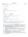
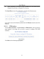
OV704WVG User Manual VER: 1.0 FCC Statement This equipment has been tested and found to comply with the limits for a Class B digital device, pursuant to part 15 of the FCC rules. These limits are designed to provide reasonable protection against harmful interference in a residential installation. This equipment generates, uses and can radiate radio frequency energy and, if not installed and used in accordance with the instructions, may cause harmful interference to radio communications. However, there is no guarantee that interference will not occur in a particular installation. If this equipment does cause harmful interference to radio or television reception, which can be determined by turning the equipment off and on, the user is encouraged to try to correct the interference by one or more of the following measures: -Reorient or relocate the receiving antenna. -Increase the separation between the equipment and receiver. -Connect the equipment into an outlet on a circuit different from that to which the receiver is connected. -Consult the dealer or an experienced radio/TV technician for help. To assure continued compliance, any changes or modifications not expressly approved by the party responsible for compliance could void the user’s authority to operate this equipment. (Example- use only shielded interface cables when connecting to computer or peripheral devices). FCC Radiation Exposure Statement This equipment complies with FCC RF radiation exposure limits set forth for an uncontrolled environment. This transmitter must not be co-located or operating in conjunction with any other antenna or transmitter. This equipment should be installed and operated with a minimum distance of 20 centimeters between the radiator and your body. This equipment complies with Part 15 of the FCC Rules.Operation is subject to the following two conditions: (1) This device may not cause harmful interference, and (2) This device must accept any interference received, including interference that may cause undesired operation. Caution! The manufacturer is not responsible for any radio or TV interference caused by unauthorized modifications to this equipment. Such modifications could void the user authority to operate the equipment. FCC - PART 68 This equipment complies with Part 68 of the FCC rules and the requirements adopted by the ACTA. On the bottom of this equipment is a label that contains, among other information, a product identifier in the format US:XXXXXXXX. If requested, this number must be provided to the telephone company. This equipment uses the following USOC jacks: RJ-11. REN (RINGER EQUIVALENT NUMBERS) STATEMENT Notice: The Ringer Equivalence Number (REN) assigned to each terminal device provides an indication of the maximum number of terminals allowed to be connected to a telephone interface. The termination on an interface may consist of any combination of devices subject only to the requirement that the sum of the Ringer Equivalence Numbers of all the devices does not exceed 5. ATTACHMENT LIMITATIONS STATEMENT Notice: This equipment meets telecommunications network protective, operational and safety requirements as prescribed in the appropriate Terminal Equipment Technical Requirements document(s). This is confirmed by marking the equipment with the Industry Canada certification number. The Department does not guarantee the equipment will operate to the user's satisfaction. Before installing this equipment, users should ensure that it is permissible to be connected to the facilities of the local telecommunications company. The equipment must also be installed using an acceptable method of connection. The customer should be aware that compliance with the above conditions may not prevent degradation of service in some situations. Repairs to certified equipment should be coordinated by a representative designated by the supplier. Any repairs or alterations made by the user to this equipment, or equipment malfunctions, may give the telecommunications company cause to request the user to disconnect the equipment. Users should ensure for their own protection that the electrical ground connections of the power utility, telephone lines and internal metallic water pipe system, if present, are connected together. This precaution may be particularly important in rural areas. Caution: Users should not attempt to make such connections themselves, but should contact the appropriate electric inspection authority, or electrician, as appropriate User Manual Contents 1 2 3 4 5 Safety Precautions .......................................................................................... 1 Overview ......................................................................................................... 2 2.1 Application .......................................................................................... 2 2.2 Features .............................................................................................. 3 2.3 Standards Compatibility and Compliance ............................................ 4 Hardware Description and Installation.............................................................. 5 3.1 Hardware Description .......................................................................... 5 3.1.1 Front Panel ............................................................................... 5 3.1.2 Rear Panel and Side Panel ....................................................... 7 3.2 Hardware Installation ........................................................................... 8 3.2.1 Choosing the Best Location for Wireless Operation .................. 8 3.2.2 Connecting the Device .............................................................. 8 PC Network Configuration and Login ............................................................. 10 4.1 PC Network Configuration ................................................................. 10 4.2 Logging In to the DSL Router ............................................................ 12 Web-Based Management .............................................................................. 13 5.1 Quick Setup ...................................................................................... 13 5.2 Advanced Setup ................................................................................ 16 5.2.1 Layer2 Interface ...................................................................... 16 5.2.2 WAN Service .......................................................................... 20 5.2.3 3G WAN Service ..................................................................... 28 5.3 Wireless ............................................................................................ 30 5.3.1 Basic Settings ......................................................................... 30 5.3.2 Security .................................................................................. 31 5.4 Voice ................................................................................................. 33 5.4.1 VoIP Status ............................................................................. 34 5.4.2 SIP Basic Setting .................................................................... 34 5.4.3 SIP Advanced Setting ............................................................. 38 5.4.4 SIP Extra Setting .................................................................... 42 5.4.5 SIP Debug Setting .................................................................. 42 5.5 Management ..................................................................................... 43 5.5.1 Access Control ....................................................................... 43 i User Manual 6 5.5.2 Update Software ..................................................................... 44 Q&A .............................................................................................................. 45 ii User Manual 1 Safety Precautions Read the following information carefully before operating the device. Please follow the following precaution items to protect the device from risks and damage caused by fire and electric power: Use volume labels to mark the type of power. Use the power adapter that is packed within the device package. Pay attention to the power load of the outlet or prolonged lines. An overburden power outlet or damaged lines and plugs may cause electric shock or fire accident. Check the power cords regularly. If you find any damage, replace it at once. Proper space left for heat dissipation is necessary to avoid any damage caused by overheating to the device. The holes on the device are designed for heat dissipation to ensure that the device works normally. Do not cover these heat dissipation holes. Do not put this device close to a place where a heat source exits or high temperature occurs. Avoid the device from direct sunshine. Do not put this device close to a place where is over damp or watery. Do not spill any fluid on this device. Do not connect this device to any PC or electronic product, unless our customer engineer or your broadband provider instructs you to do this, because any wrong connection may cause any power or fire risk. Do not place this device on an unstable surface or support. 1 User Manual 2 Overview The xDSL Router integrates wireless LAN, USB, and VoIP service into one unit. It is designed to provide a simple and cost-effective xDSL Internet connection for a private Ethernet and 802.11b/802.11g/802.11n wireless network. The Router combines high-speed xDSL Internet connection, Ethernet uplink, IP routing for the LAN and wireless connectivity in one package. It is usually preferred to provide high access performance applications for the individual users, the SOHOs, and the small enterprises. The Router supports 3G WAN service. The Router is easy to install and use. The Router connects to an Ethernet LAN or computers via standard Ethernet ports. The xDSL connection is made using ordinary telephone line with standard connectors. You can connect the Ethernet interface of WAN to Internet with Ethernet cable for ETH uplink. Multiple workstations can be networked and connected to the Internet by a single Wide Area Network (WAN) interface and single global IP address. The advanced security enhancements, packet filtering and port redirection, can help protect your network from potentially devastating intrusions by malicious agents from outside your network. Network and Router management is done through the web-based management interface that can be accessed through the local Ethernet using any web browser. You may also enable remote management to enable configuration of the Router via the WAN interface. 2.1 Application Home gateway SOHOs Small enterprises Higher data rate broadband sharing Audio and video streaming and transfer PC file and application sharing Network and online gaming Voice over IP (VoIP) USB storage 2 User Manual 3G WAN service 2.2 Features User-friendly GUI for web configuration Several pre-configured popular games. Just enable the game and the port settings are automatically configured. Compatible with all standard Internet applications Industry standard and interoperable DSL interface Simple web-based status page displays a snapshot of system configuration, and links to the configuration pages Downloadable flash software updates Support for up to 8 permanent virtual circuits (PVC) Support for up to 8 PPPoE sessions Support RIP v1 & RIP v2 WLAN with high-speed data transfer rates, compatible with IEEE 802.11b/g/n Optimized Linux 2.6 Operating System IP routing and bridging Asynchronous transfer mode (ATM) and digital subscriber line (DSL) support Packet Transfer Mode (PTM) Ethernet (ETH) Transfer Mode Point-to-point protocol (PPP) Network/port address translation (NAT/PAT) Quality of service (QoS) Wireless LAN security: WPA, 802.1x, RADIUS client Universal plug-and-play(UPnP) File server for network attached storage (NAS) devices Print server Web filtering Management and control Web-based management (WBM) Command line interface (CLI) TR-069 WAN management protocol Simple Network Management Protocol (SNMP) Remote update System statistics and monitoring 3 User Manual DSL router is targeted at the following platforms: DSL modems, wireless access points and bridge. 2.3 Standards Compatibility and Compliance Support application level gateway (ALG) ITU G.992.1 (G.dmt) ITU G.992.2 (G.lite) ITU G.994.1 (G.hs) ITU G.992.3 (ADSL2) ITU G.992.5 (ADSL2+) ITU G.993.1 (VDSL) ITU G993.2 (VDSL2) 3G (WCDMA, CDMA2000, TD-SCDMA) ANSI T1.413 Issue 2 IEEE 802.3 IEEE 802.3u IEEE 802.11b IEEE 802.11g IEEE 802.11n RFC3261 (SIP for VoIP) 4 User Manual 3 Hardware Description and Installation Note: The figures in this document are for reference only. 3.1 Hardware Description 3.1.1 Front Panel Figure 1 Front panel The following table describes the indicators on the front panel. Indicator Color Status Description Green Power Red DSL Internet Green Green Red On The device is powered on and the device operates normally. Blink The software is upgrading. Off The device is powered off. On The device is initiating. Blink The software is upgrading. On DSL link has established. Blink The DSL line is training. Off Device is powered off. On Internet is synchronized successfully in the route mode. Blink Internet data is being transmitted. Off Ethernet interface is disconnected. On Authentication has failed. Blink The WAN interface is connected to the Ethernet cable. Network data is transmitting. Off The WAN interface is not connected to the On WAN Green 5 User Manual Indicator Color Status Description Ethernet cable. LAN 1/2/3/4 WiFi WPS USB1/2 Phone1/2 Green Green Green Green Green On The Ethernet interface is connected. Blink Data is being transmitted through the Ethernet interface. Off The Ethernet interface is disconnected. On WIFI is enabled. Blink Data is being transmitted through the wireless interface. Off WIFI is disabled. On Connection succeeds under Wi-Fi Protected Setup. Blink Negotiation is in progress under Wi-Fi Protected Setup. Off Wi-Fi Protected Setup is disabled. On The connection of 3G or USB flash disk has established. Blink Data is being transmitted. Off No signal is detected. Off No FXS signal is detected. Blink The user data is passing through FXS port. On The FXS interface is ready to work. 6 User Manual 3.1.2 Rear Panel and Side Panel Figure 2 Rear panel Figure 3 Side panel The following table describes the interfaces and the buttons. Interface Description DSL RJ-11 port. Connect the router to DSL connector or splitter through telephone cable. Phone1/2 RJ-11 port, using the telephone cable to connect the telephone set. LAN 4~1 RJ-45 port, for connecting the router to a PC or another network device. WAN For connecting Ethernet cable to provide Ethernet uplink. Reset Press the button for at least 1 second and then release it. System restores the factory default settings. USB1/2 USB port, for connecting the 3G network card or other USB storage devices. Power On/Off Power interface, for connecting the power adapter. WiFi WiFi switch, for enabling or disabling the WiFi function. Power switch. 7 User Manual Interface WPS Description This button is used for enabling WPS PBC mode. If WPS is enabled, press this button, and then the wireless router starts to accept the negotiation of PBC mode. Warning: Do not press the Reset button unless you want to clear the current settings. The Reset button is in a small circular hole on the rear panel. If you want to restore the default settings, please press the Reset button gently for 1 second with a fine needle inserted into the hole and then release the button. The system reboots and returns to the factory defaults. 3.2 Hardware Installation 3.2.1 Choosing the Best Location for Wireless Operation Many environmental factors may affect the effective wireless function of the DSL Router. If this is the first time that you set up a wireless network device, read the following information: The access point can be placed on a shelf or desktop, ideally you should be able to see the LED indicators in the front, as you may need to view them for troubleshooting. Designed to go up to 100 meters indoors and up to 300 meters outdoors, wireless LAN lets you access your network from anywhere you want. However, the numbers of walls, ceilings, or other objects that the wireless signals must pass through limit signal range. Typical ranges vary depending on types of materials and background RF noise in your home or business. 3.2.2 Connecting the Device Step 1 Connect the DSL port of the router and the Modem port of the splitter with a telephone cable; connect the phone to the phone port of the splitter through a cable; and connect the incoming line to the Line port of the splitter. The spliiter has three ports: Line: Connect to a wall phone jack (RJ-11 jack) Modem: Connect to the Line interface of the router 8 User Manual Phone: Connect to a telephone set Connect the LAN port of the router to the network card of the PC through an Ethernet cable. Step 3 Plug the power adapter to the wall outlet and then connect the other end of it to the Power port of the router. The followig figure displays the connection of the DSL router, PC, and telephones. Step 2 Figure 4 Connecting the DSL router Note: If you use 3G WAN service, connect the 3G USB data card to the USB port of the router. If you use the Ethernet uplink, connect the WAN interface that is defined to the Internet with Ethernet cable. The xDSL uplink, 3G WAN service, and Ethernet uplink can not coexist. 9 User Manual 4 PC Network Configuration and Login 4.1 PC Network Configuration Each network interface on the PC should either be configured with a statically defined IP address and DNS address, or be instructed to automatically obtain an IP address using the network DHCP server. DSL router provides a DHCP server on its LAN and it is recommended to configure your LAN to automatically obtain its IP address and DNS server IP address. The configuration principle is identical but should be carried out differently on each operating system. The following displays the TCP/IP Properties dialog box on Windows XP. 10 User Manual Figure 5 IP and DNS configuration TCP/IP configuration steps for Windows XP are as follows: Step 1 Choose Start > Control Panel > Network Connections. Step 2 Right-click the Ethernet connection icon and choose Properties. Step 3 On the General tab, select the Internet Protocol (TCP/IP) component and click Properties. Step 4 The Internet Protocol (TCP/IP) Properties window appears. 11 User Manual Step 5 Step 6 Step 7 Step 8 Select the Obtain an IP address automatically radio button. Select the Obtain DNS server address automatically radio button. If you want to set the IP address and subnet mask manually, you can set the IP address and subnet mask of the computer to 192.168.1.x and 255.255.255.0 respectively. The range for x is from 2 to 254. Click OK to save the settings. 4.2 Logging In to the DSL Router To log in to the DSL router, do as follows: Step 1 Open a Web browser on your computer. Step 2 Enter http://192.168.1.1 (the default IP address of the DSL router) in the address bar. The login page appears. Step 3 Enter the user name and the password. The default username and password of the super user are admin and admin. The username and password of the common user are user and user. You need not enter the username and the password again if you select the option Remember my password. It is recommended to change these default values after logging in to the DSL router for the first time. Step 4 Click OK to log in to the Web page. Otherwise, please click Cancel to exit the login page. 12 User Manual Figure 6 Login page After logging in to the DSL router as a super user, you can query, configure, and modify all the settings, and diagnose the system 5 Web-Based Management This chapter describes how to use Web-based management of the DSL router, which allows you to configure and control all of DSL router features and system parameters in a user-friendly GUI. 5.1 Quick Setup Choose Quick Setup and the following page is displayed. 13 User Manual VPI (Virtual Path Identifier): The virtual path between two points in an ATM network, and its valid value is from 0 to 255. VCI (Virtual Channel Identifier): The virtual channel between two points in an ATM network, ranging from 32 to 65535 (1 to 31 are reserved for known protocols). Encapsulation Mode: LLC/SNAP-BRIDGING, or VC/MUX Protocol: You can select the following items from the drop-down list: PPPoE, DHCP, PPPoA, IPoA, or Bridge. 14 User Manual PPP Username: The correct user name provided by your ISP. PPP Password: The correct password provided by your ISP. Use Static IP Address: If this function is disabled, the modem obtains an IP address assigned by an uplink equipment such as BAS, through PPPoE dial-up. If this function is enabled, the modem uses this IP address as the WAN IP address. SSID: The service set identification (SSID) is a unique name to identify the router in the wireless LAN. Wireless stations associating to the router must have the same SSID. Enter a descriptive name that is used when the wireless client connecting to the router. Select Automatic Configuration to display the following page. PPP Username: The correct user name provided by your ISP. PPP Password: The correct password provided by your ISP. SSID: The service set identification (SSID) is a unique name to identify the router in the wireless LAN. Wireless stations associating to the router must have the same SSID. Enter a descriptive name that is used when the wireless client connecting to the router. After finishing setting, click Apply/Save to save the settings. 15 User Manual 5.2 Advanced Setup 5.2.1 Layer2 Interface 5.2.1.1 ATM Interface Choose Advanced Setup > Layer2 Interface > ATM Interface . In this page, you can add or remove to configure DSL ATM Interfaces. Click Add to add ATM Interface and the following page appears. 16 User Manual In this page, you can enter this PVC (VPI and VCI) value, and select DSL link type (EoA is for PPPoE, IPoE, and Bridge.), encapsulation mode, service category. VPI (Virtual Path Identifier): The virtual path between two points in an ATM network, and its valid value is from 0 to 255. VCI (Virtual Channel Identifier): The virtual channel between two points in an ATM network, ranging from 32 to 65535 (1 to 31 are reserved for known protocols). DSL Link Type: EoA (it is for PPPoE, IPoE, and Bridge), PPPoA, or IPoA Encapsulation Mode: LLC/SNAP-BRIDGING, or VC/MUX Service Category: UBR Without PCR, UBR With PCR, CBR, Non Realtime VBR, Realtime VBR. 17 User Manual Select Scheduler for Queues of Equal Precedence as the Default Queue: Weighted Round Robin or Weighted Fair Queuing. Click Apply/Save to save the configuration, and return the following page: If you want to remove this Interface, please select the Remove check box and click Remove. 5.2.1.2 PTM Interface Choose Advanced Setup > Layer2 Interface > PTM Interface, and the following page appears. In this page, you can add or remove to configure PTM WAN Interfaces. Click Add and the following page appears. 18 User Manual In this page, you can select scheduler for queues of equal precedence and enter the queue value. Click Apply/Save to save configuration. 5.2.1.3 ETH Interface Choose Advanced Setup > Layer2 Interface > ETH Interface, and the following page appears. In this page, you can add or remove to configure ETH WAN Interfaces. 19 User Manual Click Add and the following page appears. In this page, you can select a ETH port. Click Apply/Save to save configuration. Note: If ETH Interface is selected, there are two WAN service types (PPPoE and IPoE). 5.2.2 WAN Service Choose Advanced Setup > WAN Service, and the following page appears. In this page, you are allowed to add, remove, or edit a WAN service. Note: If PTM Interface is selected, there are three WAN service types: PPP over Ethernet (PPPoE), IP over Ethernet, Bridging. And the corresponding configurations of PTM WAN service are same as the configurations of ATM WAN service. 20 User Manual 5.2.2.1 Adding a PPPoE WAN Service This section describes the steps for adding the PPPoE WAN service. Step1 In the Wide Area Network (WAN) Service Setup page, click the Add button to display the following page. (At first, you must add a proper ATM or PTM interface for this WAN service.) Step2 In this page, you can select a ATM Interface for the WAN service. After selecting the ATM interface, click Next to display the following page. 21 User Manual Step3 In this page, select the WAN service type to be PPP over Ethernet (PPPoE). Click Next to display the following page. 22 User Manual Step4 In this page, you can modify the PPP username, PPP password, PPPoE service name and authentication method. PPP Username: The correct user name provided by your ISP. PPP Password: The correct password provided by your ISP. PPPoE Service Name: If your ISP provides it to you, please enter it. If not, do not enter any information. Authentication Method: The value can be AUTO, PAP, CHAP, or MSCHAP. Usually, you can select AUTO. Enable Fullcone NAT:. NAT is one where all requests from the same internal IP address and port are mapped to the same external IP address and port. Furthermore, any external host can send a packet to the internal host, by sending a packet to the mapped external address. Dial on demand (with idle timeout timer): If this function is enabled, you need to enter the idle timeout time. Within the preset minutes, if the modem does not detect the flow of the user continuously, the modem automatically stops the PPPoE connection. Once it detects the flow (like access to a webpage), the modem restarts the PPPoE dialup. If this function is disabled, the modem performs PPPoE dial-up all the time. The PPPoE connnection 23 User Manual does not stop, unless the modem is powered off and DSLAM or uplink equipment is abnormal. PPP IP extension: If you want to configure DMZ Host, you should enable it first. Use Static IPv4 Address: If this function is disabled, the modem obtains an IP address assigned by an uplink equipment such as BAS, through PPPoE dial-up. If this function is enabled, the modem uses this IP address as the WAN IP address. Enable PPP Debug Mode:Enable or disable this function. Bridge PPPoE Frames Between WAN and Local Ports:Enable or disable this function. Enable IGMP Multicast Proxy:If you want PPPoE mode to support IPTV, enable it. Step5 After setting the parameters, click Next to display the following page. Step6 In this page, select a preferred WAN interface as the system default gateway and then click Next to display the following page. 24 User Manual Step7 In this page, you can obtain the DNS server addresses from the selected WAN interface. Click Next, and the following page appears. Step8 In this page, it displays the information about the PPPoE settngs. Click Apply/Save to save and apply the settings. 5.2.2.2 Adding a Bridge WAN service This section describes the steps for adding the Bridge WAN service. Step1 In the Wide Area Network (WAN) Service Setup page, click the Add button to display the following page. (At first, you must add a proper ATM 25 User Manual or PTM interface for this WAN service.) Click the Add button to display the following page. Step2 Select the proper ATM Interface and then click Next to display the following page. 26 User Manual Step3 In this page, you can select the WAN service type, and modify the service description for this service. After finishing setting, click Next to display the following page. 27 User Manual Step4 In this page, it displays the information about the bridge settngs. Click Apply/Save to save and apply the settings. You can modify the settings by clicking the Back button if necessary. 5.2.3 3G WAN Service Choose Advanced Setup > 3G Wan Service , and the following page appears. This page is used to configure 3G connection. If you want to access the Internet through 3G connection, a 3G network card is required. Connect the 3G network card to the USB interface of the Router. Information: Click it to display the information of the 3G network card. Upload Driver: For a un-support USB dongle, click it to upload the new driver for supporting the USB. The driver is a text file. Click Add in the WAN Service for 3G Mobile Setup to display the following page. 28 User Manual In this page, you are allowed to configure the settings of the 3G USB modem. Enable USB Modem: If you want to access the Internet through the 3G network card, you must enable the USB modem. User Name: Username provided by your 3G ISP. Password: Password provided by your 3G ISP. Authentication Method: Select a proper authentication method in the drop down list. You can select Auto, PAP, CHAP, or MSCHAP. APN: APN (Access Point Name) is used to identify the service type. Enter the APN provided by your 3G ISP. Dial Number: Enter the dial number provided by your 3G ISP. Idle time (in sec.): If no traffic for the preset time, the 3G will disconnect automatically. Dial Delay (in sec.): The 3G delays dial after the DSL is disconnected. Default WAN Connection Select: You can select DSL or ETHERNET or 3G from the drop-down list. WAN back mechanism: The 3G connection is backup for the DSL connection. 29 User Manual – - DSL: If the DSL is disconnected, the 3G starts to dial. – - IP connectivity: If the system fails to ping the specified IP address, the 3G starts to dial. After finishing setting, click the Apply/Save button to save the settings. You may also click the Auto Setting button to automatically configure the 3G connection. 5.3 Wireless Choose Wireless and the submenus of Wireless are shown as below: 5.3.1 Basic Settings Choose Wireless > Basic to display the following page. In this page, the figure in the right area is 2-dimensional code. It includes the wireless SSID and password. You can obtain the wireless SSID and password through scanning this figure. 30 User Manual This page allows you to configure the basic features of the wireless LAN interface. Enable Wireless: Enable or disable the wireless function. Hide Access Point: if you want to hide any access point for your router, select this option, and then a station cannot obtain the SSID through the passive scanning. Clients Isolation: When many clients connect to the same access point, they can access each other. If you want to disable the access between the clients that connect to the same access point, you can select this option. Disable WMM Advertise: After enabling this option, the transmission performance multimedia of the voice and video data can be improved. Enable Wireless Multicast Forwarding (WMF): After enabling this option, the transmission quality of video service such as IPTV can be improved. SSID: For the security reason, you should change the default SSID to a unique name. BSSID: Display the MAC address of the wireless interface. Country: The name of the country with which your gateway is configured. This parameter further specifies your wireless connection. For example, the channel will adjust according to nations to adapt to each nation's frequency provision. Max Clients: Specify the maximum wireless client stations to be enabled to link with AP. Once the clients exceed the max vlaue, all other clients are refused. The value of maximum clients is 16. Wireless - Guest/Virtual Access Points: If you want to make Guest/Virtual network function be available, you have to check those boxes in the table below. In the current software version, three virtual access points can be configured. After finishing setting, click Apply/Save to save the basic wireless settings and make the settings take effect. 5.3.2 Security Choose Wireless > Security to display the following page. 31 User Manual This page allows you to configure the security features of the wireless LAN interface. In this page, you can configure the network security settings by the Wi-Fi Protected Setup (WPS) method or setting the network authentication mode. WPS Setup 32 User Manual There are 2 primary methods used in the Wi-Fi Protected Setup: PIN entry, a mandatory method of setup for all WPS certified devices. – Enter STA PIN: If you select it, you need to enter the station PIN from client. – Use AP PIN: The PIN is generated by AP. Push button configuration (PBC), an actual push button on the hardware or through a simulated push button in the software. (This is an optional method on wireless client). If you are using the PIN method, you will need a Registrar (access point/wireless router) to initiate the registration between a new device and an active access point/wireless router. (Note: The PBC method may also need a Registrar when used in a special case where the PIN is all zeros) In order to use the push-button for WPS authentication, you must ensure that the network card support the function. if it supports, you need not to do any configuration. You can press the WPS button directly to enable the WPS function. 5.4 Voice Choose Voice and the submenus of Voice are shown as below. 33 User Manual 5.4.1 VoIP Status Choose Voice > VoIP Status and the Voice Status page appears. In the Registration Status field, Up means registered successfully, Down means unregistered, Disable means account is not enabled. 5.4.2 SIP Basic Setting Choose Voice > SIP Basic Setting, and the following page appears. 34 User Manual 35 User Manual Figure 7 SIP Basic Setting Bound Interface Name: you can select the bound interface name from the drop-down list. SIP Local Port: Set the SIP local port of the gateway, the default value is 5060. SIP local port is the SIP UA (user agent) port. SIP domain name: Enter the SIP domain name that you want to set. Use SIP Proxy: Select the checkbox of Use SIP Proxy, if your DSL router uses a SIP proxy. SIP proxy allows other parties to call DSL router through it. When it is selected, the following fields appear. – – SIP Proxy: The IP address of the proxy. SIP Proxy port: The port that this proxy is listening on. By default, the port value is 5060. Use SIP Outbound Proxy: Some network service providers require the use of an outbound proxy. This is an additional proxy, through which all outgoing calls are directed. In some cases, the outbound proxy is placed alongside the firewall and it is the only way to let SIP traffic pass from the internal network to the Internet. When it is selected, the following fields appear. – SIP Outbound Proxy: The IP address of the outbound proxy. 36 User Manual – SIP Outbound Proxy port: The port that the outbound proxy is listening on. By default, the port value is 5060. Use SIP Registrar: Select the checkbox of Use SIP Registrar to register with the proxy. You can register your user ID on the SIP registrar. SIP registrar works with SIP proxy, allowing other parties to call DSL router through it. When it is selected, the following fields appear. – – SIP Registrar: The IP address of the SIP registrar. SIP Registrar port: The port that SIP registrar is listening on. By default, the port value is 5060. Account Enabled: If it is unselected, the corresponding account is disabled. You can not use it to initiate or accept any call. Polarity Reverse Enable: Enable or disable this function. Authentication name: Set the user name of authentication. Password: Set the password of authentication. Cid Name: User name. It is the Display Name. Cid Number: Set the caller number. It must be a number of 0~9. ptime: You can use it to set the packetization time (PT). The PT is the length of the digital voice segment that each packet holds. The default is 20 millisecond packets. If selecting 10 millisecond, packets improve the voice quality. Because of the packet loss, less information is lost, but more loads on the network traffic. Priority: The priority of codec is declined from up to down. Codecs define the method of relaying voice data. Different codecs have different characteristics, such as data compression and voice quality. For Example, G723 is a codec that uses compression, therefore, it is good for use where the bandwidth is limited but its voice quality is not good as other codecs, such as the G711. If you specify none of the codecs, using the default value showed in the above figure, the DSL router chooses the codec automatically. After setting, click Apply to take the settings in to effect. 37 User Manual 5.4.3 SIP Advanced Setting Choose Voice > SIP Advanced Setting, and the following page appears. 38 User Manual 39 User Manual Figure 8 SIP Advanced Setting Line: It displays the line you want to configure. Call waiting: If call waiting is enabled on a line, you can hear the call waiting tone during a call, press FLASH on the phone to answer the second call. The first call is automatically placed on hold. To switch between calls, press FLASH again. Select Call waiting to enable this feature. Call forward feature settings (Busy or All) take priority over the call waiting feature. Call waiting feature is ignored on new incoming calls if there is already a call on hold or in conference. Unconditionally Call forwarding number: Enter the number that you want to set. It is the feature that forwards all incoming calls to an appointed number unconditionally. Busy Call forwarding number: Enter the number that you want to set. It is a feature that forwards all incoming calls to an appointed number when the line is busy. No Answer Call forwarding number: Enter the number that you want to set. It is a feature that forwards all incoming calls to an appointed number when the call is not answered. Options Time: Set the time interval for sending the Options message. Forward unconditionally: Select the check box to enable this function. Forward on "busy": Select the check box to enable this function. Forward on "no answer": Select the check box to enable this function. MWI: When selecting message waiting indicator (MWI), the DSL router sends a SIP SUBSCRIBE message to the proxy, asking for a notification when its voicemail status changes. When its status does change, the proxy send a NOTIFY message to the gateway, causing a MWI tone streamed to user’s receiver. Anonymous call blocking It is a feature that can block the anonymous call. Select the checkbox of Anonymous call blocking to enable this feature. You can also dial *77 to enable this feature. Dial *87 to disable this feature. Anonymous calling It is a feature that allows using anonymous name as a call number when calling out. 40 User Manual Select the checkbox of Anonymous calling to enable this feature. You can also dial *68 to enable this feature. Dial *82 to disable this feature. DND It is a feature to reject all incoming calls. Select the checkbox of DND to enable this feature. You can also Dial *78 to enable the feature. Enable Call Return: Select the check box to enable this function. Fax Negotiate Mode: You can select it from the drop-down list. Bypass Codec: You can select it from the drop-down list. Enable T38 redundancy support: Select the check box to enable this function. Enable vbd redundancy support: Select the check box to enable this function. RFC2198 Payload Value (range 96~127): Enter the RFC2198 payload value that the valid range is 96 ~ 127. Registration Expire Timeout*: Enter the registration expire timeout. Session Expire Time: The interval of dialog refreshing time. Min Session Expire Time: The minimum interval of dialog refreshing time. VoIP DialPlan Setting: Set the VoIP dial plan. If user-dialed number matches it, the number is processed by the DSL router immediately. DSCP for SIP: Set the DSCP for SIP. You can select it from the drop-down list. DSCP for RTP: Set the DSCP for RTP. You can select it from the drop-down list. Dtmf Relay Setting: Set DTMF transmit method, which can be following values: – SIP Info: Use SIP INFO message to transmit DTMF digits. 41 User Manual – RFC2833: Use RTP packet to encapsulate DTMF events, as specified in RFC 2833. – InBand: DTMF events are mixed with user voice in RTP packet. SIP Transport Protocol: Select the transport protocol to use for SIP signaling. Note that the SIP proxy and registrar need to support the protocol you select. Enable Local Supplementary Service: Select the checkbox to enable the supplementary service settings by the telephone set. If you deselect the checkbox, the supplementary service can not be set by the telephone set. After setting, click Apply to take the settings in to effect. 5.4.4 SIP Extra Setting Choose Voice > SIP Extra Setting, and the following page appears. Dial tone time: Dial tone duration. Busy tone time: Busy tone duration. Inter digit time: The valid range is 1 ~ 5. Offhook warning tone time: Offhook warning tone duration. Ringback tone time: Ringback tone duration. After setting, click Apply to take the settings in to effect. 5.4.5 SIP Debug Setting Choose Voice > SIP Debug Setting, and the following page appears. 42 User Manual Vodsl Console Log Level: Select it from the drop-down list. SIP Log Server Settings: Set SIP log server IP address and port, then the log message of the VoIP is sent to the device which IP address you set to. If you want use this function, both of the IP address and port must be set correctly. Gain Settings: Gain is a measure of the ability of a circuit (often an amplifier) to increase the power or amplitude of a signal. You can increase or decrease ingress gain and egress gain. The range of the value is from -14 to 6. 5.5 Management 5.5.1 Access Control Passwords Choose Management > Access Control > Passwords, and the following page appears. 43 User Manual In the page, you can modify the username and password of different users. After finishing setting, click the Apply/Save button to save and apply the settings. 5.5.2 Update Software Choose Management > Update Software, and the following page appears. If you want to upload the software, click the Browse… button to choose the new software, and then click the Update Software button. Note: When software update is in progress, do not shut down the router. After software update completes, the router automatically reboots. Please make sure that the new software for updating is correct, and do not use other software to update the router. 44 User Manual 6 Q&A (1) (2) (3) (4) (5) (6) Q: Why all the indicators are off? A: Check the following: The connection between the power adaptor and the power socket. The status of the power switch. Q: Why the LAN indicator is off? A: Check the following: The connection between the ADSL router and your computer, hub, or switch. The running status of your PC, hub, or switch. Q: Why the DSL indicator is off? A: Check the connection between the “DSL” port of router and the wall jack. Q: Why Internet access fails while the DSL indicator is on? A: Check whether the VPI, VCI, user name, and password are correctly entered. Q: Why I fail to access the web configuration page of the DSL router? A: Choose Start > Run from the desktop, and ping 192.168.1.1 (IP address of the DSL router). If the DSL router is not reachable, check the type of the network cable, the connection between the DSL router and the PC, and the TCP/IP configuration of the PC. Q: How to load the default settings after incorrect configuration? A: To restore the factory default settings, turn on the device, and press the reset button for at least 1 second, and then release it. The default IP address and the subnet mask of the DSL router are 192.168.1.1 and 255.255.255.0, respectively. User/password of super user: admin/admin User/password of common user: user/user 45