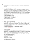
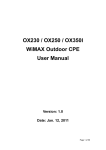
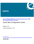
1
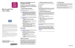
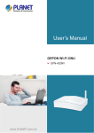
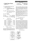
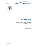
TRIPLEPLAY150 User Manual TriplePlay150 User Manual Contents 1 2 3 4 Introduction ........................................................................................................ 1 1.1 LEDs and Interfaces .............................................................................. 1 1.2 System Requirements ........................................................................... 4 1.3 Features ................................................................................................ 4 Hardware Installation ......................................................................................... 5 2.1 DSL Uplink Connection ......................................................................... 5 2.2 Ethernet Uplink Connection................................................................... 6 Web Configuration ............................................................................................. 7 3.1 Network Configuration of PC ................................................................. 7 3.2 Access the Router ................................................................................. 9 3.2.1 WAN Service ............................................................................ 10 3.3 3G WAN Service ................................................................................. 18 3.4 Wireless Configuration ........................................................................ 21 3.4.1 Basic Settings ........................................................................... 21 3.4.2 Wireless Security ...................................................................... 23 3.5 Voice.................................................................................................... 32 3.5.1 VoIP Status ............................................................................... 32 3.5.2 SIP Basic Setting ...................................................................... 33 3.5.3 SIP Advanced Setting ............................................................... 36 3.5.4 SIP Digit Map Setting................................................................ 40 3.5.5 SIP Extra Setting ...................................................................... 41 3.5.6 SIP Debug Setting .................................................................... 41 Questions & Answers ....................................................................................... 43 1 Introduction The device is a network access device designed for home users or small office users, which supports multiple line modes. It provides four 10/100 base-T Ethernet interfaces, two FXS interfaces, one USB interface and one WAN interface at the user end. The device provides high performance access to the Internet, downlink up to 24 Mbps and uplink up to 1 Mbps. The device supports 3G and WLAN accesses. It connects to the Internet through a WLAN AP or WLAN device. It complies with IEEE 802.11, 802.11b/g/n specifications, WEP, WPA, and WPA2 security specifications. In the IEEE 802.11n mode, 2T2R can reach the maximum wireless transmission rate of 270 Mbps. 1.1 LEDs and Interfaces Front Panel The following table describes the LEDs of the device: LED Color Green Power Red DSL Green Status Description On The device is powered on and the device operates normally. Blinking The software is upgrading. Off The device is powered off. On The device is initiating. Blinking The software is upgrading. On The ADSL line is established. Slow Blinking No DSLAM’s detected. Fast Blinking The ADSL line is training. 1 signal is being LED Internet Color WAN USB WLAN WPS Green Green Green Green Green Description The device is powered off. On Connection to the Internet is established in the routing mode, for example, PPP dialing is successful, and no data is being transmitted. Blinking Internet data is being transmitted in the routing mode. Off The device is under the bridge mode. On The Internet authentication fails. On The LAN connection is normal. Blinking Data is being transmitted or received through the LAN interface. Off The LAN established. On The connection to the office end has been established successfully. Blinking Data is being transmitted via WAN Off The WAN connection is failed. On The USB/3G connection is activated and works normally. Fast Blinking Data is being transmitted or received through the USB interface. Off The USB/3G connected. On The WLAN established. Blinking Data is being transmitted or received through the WiFi interface. Off The WLAN established. On Connection succeeds under Wi-Fi Protected Setup. Blinking Negotiation is in progress under Wi-Fi Protected Setup. Green Red LAN 1/2/3/4 Status Off 2 connection interface is not is not connection is connection is not LED FXS 2/1 Color Green Status Description Off Wi-Fi Protected Setup is disabled On The Phone interface of VoIP service is ready to work. Blinking The user data is passing through FXS interface. Off No FXS signal is detected. Rear Panel The following table describes the interfaces and buttons of the device: Interface Description DSL RJ-11 interface, for connecting to the ADSL interface or a splitter through a telephone cable. FXS1/2 RJ-11 port, using the telephone line to connect a telephone to provide VoIP service. WAN Connect Ethernet cable to establish WAN connection. LAN 4/3/2/1 RJ-45 interface, for connecting to the Ethernet interface of a PC through Ethernet cable. USB USB interface, for connecting to the 3G network or USB Ethernet connection. WPS To enable or disable WPS. Press the button and hold it over 3 seconds, to initialize WPS negotiation. WLAN To enable or disable WLAN. Press the button and hold it for 1 second to enable WLAN. Reset Reset to the factory defaulted configuration. Keep the device powered on, and insert a needle into the hole for 3 seconds, then release it. The device is reset to the factory defaulted configuration. 3 Interface Description On/Off Power switch, power on or power off the device. Power Power interface, for connecting to the power adapter of 12 V DC, 1.5A. 1.2 System Requirements Recommended system requirements are as follows: A 10/100 base-T Ethernet card is installed on your PC. A hub or Switch. (connected to several PCs through one of Ethernet interfaces on the device) Operating system: Windows 7, Windows Vista, Windows XP, Windows 2000, Windows ME, or Windows 98 SE. Internet Explorer V5.0 or higher, Netscape V4.0 or higher, or Firefox 1.5 or higher. 1.3 Features The device supports the following features: Compatible with IEEE 802.11b/g/n standard High-speed wireless data transfer: up to 270 Mbps Various line modes External PPPoE dial-up access Internal PPPoE and PPPoA dial-up access 1483 Bridged, 1483 Routed, and MER access Multiple PVCs (up to eight) that can be isolated from each other A single PVC with multiple sessions Multiple PVCs with multiple sessions Binding of ports with PVCs 802.1Q DHCP server NAT and NAPT Static routing Firmware upgrade through Web or TFTP Restore to the factory defaults DNS 4 Virtual server DMZ Three-level user accounts Web user interface Telnet CLI System status displaying PPP session PAP, CHAP, and MS-CHAP IP filter IP QoS Remote access control Line connection status test Remote management through telnet or HTTP Backup and restoration of configuration file Ethernet interface supports crossover detection, auto-correction and polarity correction Universal plug and play (UPnP) 3G WAN Service Support VoIP Service 2 Hardware Installation 2.1 DSL Uplink Connection Step 1 Connect the DSL interface of the device to the MODEM interface of the splitter through a telephone cable. Connect a phone to the PHONE interface of the splitter through a telephone cable. Connect the incoming line to the LINE interface of the splitter. The splitter has three interfaces: LINE: Connect to a wall phone jack (RJ-11 jack). MODEM: Connect to the ADSL jack of the device. PHONE: Connect to a telephone set. Step 2 Connect the LAN interface of the device to the network interface card (NIC) of the PC through an Ethernet cable (MDI/MDIX). 5 Note: Use twisted-pair cables to connect with the hub or Switch. Step 3 Plug the power adapter to the wall outlet and the other end to the Power interface of the device. FFigure 1 displays the application diagram for the connection of the device, PC, splitter, and telephone sets, when no telephone set is placed before a splitter. Figure 1 Connection diagram in the mode of DSL uplink connection 2.2 Ethernet Uplink Connection Step 1 Connect the LAN interface of the wireless router to your PC with RJ45 Step 2 Ethernet cable. Connect the WAN interface of the wireless router to the uplink network device with RJ45 Ethernet cable. Step 3 Connect the power adapter to the power socket of the wireless router. Figure 2 displays the application diagram for the connection of the device, PC, splitter, and telephone sets, when no telephone set is placed before a splitter. 6 Figure 2 Connection diagram in the mode of Ethernet uplink connection 3 Web Configuration This chapter describes how to configure the device by using the Web-based configuration utility. 3.1 Network Configuration of PC Before accessing the router, you need to configure the Internet protocol property of the connected PC. The following instructions describe how to configure the IP address of the PC. (Take Windows XP as an example) Step 1 In the desktop, right click the icon of My Network Places. Then select Properties in the menu. Step 2 Right-click the icon of Local Network Area and select Properties in the menu. The page as following figure appears. 7 Step 3 In the Local Area Connection Properties window, click the General tab, and then double-click Internet Protocol (TCP/IP). The page as following figure appears.. 8 There are two methods of obtaining an IP address: Obtain an IP address automatically: The IP address is assigned by Dynamic Host Configuration Protocol (DHCP). Use the following IP address: Set the IP address of the PC to the same network segment with the router. By default, the IP address of the router is 192.168.1.1. The IP address of the PC can be set to 192.168.1.x (2 to 254), subnet mask to 192.168.1.1, default gateway to 192.168.1.1. 3.2 Access the Router Follow the steps below to access the router for the first time: Step 1 Open the Internet Explorer (IE) and then enter http://192.168.1.1/. Step 2 You are required to enter a username and a password. The username and password of the super user are admin/admin. Step 3 Click OK to enter the Web configuration page of the router. If you log in successfully, the page as the following figure will appear. You can view the device information including Board ID, manufacturer and serial number and so on. You can also view the status of the WAN connection. 9 3.2.1 WAN Service Choose Advance Setup > WAN Service, and the following page appears. In this page, you are allowed to add, remove, or edit a WAN service. 10 3.2.1.1 Adding a PPPoE WAN Service This section describes how to add a PPPoE WAN service. Step1 In the Wide Area Network (WAN) Service Setup page, click the Add button to display the following page. Step2 In this page, select an Ethernet Interface for the WAN service, then click Next to display WAN Service Configuration page. 11 Step3 In this page, you can set the VLAN. Enable 802.1Q VLAN: to enable the configuration of VLAN, such as set priority and ID for a VLAN. 12 Enter 802.1P Priority [0-7]: The IEEE 802.1p establishes eight levels of priority (0 ~ 7). Seven is the highest priority. Five and six are often for delay-sensitive applications. Data classes four through one range from controlled-load applications Zero is used as a best-effort default priority, invoked automatically when no other value has been set. Enter 802.1Q VLAN ID [0-4094]: VID (VLAN ID) is the identification of the VLAN, which is basically used by the standard 802.1Q. The VID 0 is used to identify priority frames and value 4095 (FFF) is reserved, so the maximum possible VLAN configurations are 4,094. Enable IPv6 for this service If check this checkbox, this service will support IPv6. Check Enable 802.1Q VLAN and click next, the page as following figure appears. 13 Step4 In this page, you can modify the PPP username, PPP password, PPPoE service name and authentication method. PPP Username: The correct user name provided by your ISP. PPP Password: The correct password provided by your ISP. PPPoE Service Name: If your ISP provides it to you, please enter it. If not, do not enter any information. Authentication Method: Choose a method to verify your PPP username and password. Your can choose AUTO, PAP, CHAP, MSCHAPV1 or MSCHAPV1 from the dropdown list. Usually, you can select AUTO. Enable Fullcone NAT:. NAT is one where all requests from the same internal IP address and port are mapped to the same external IP address 14 and port. Furthermore, any external host can send a packet to the internal host, by sending a packet to the mapped external address. Dial on demand (with idle timeout timer): If this function is enabled, you need to enter the idle timeout time. Within the preset minutes, if the modem does not detect the flow of the user continuously, the modem automatically stops the PPPoE connection. Once it detects the flow (like access to a webpage), the modem restarts the PPPoE dialup. If this function is disabled, the modem performs PPPoE dial-up all the time. The PPPoE connnection does not stop, unless the modem is powered off or ethernet connection works abnormally. PPP IP extension: If you want to configure DMZ Host, you should enable it first. Use Static IPv4 Address: If this function is disabled, the modem obtains an IP address assigned by an uplink equipment such as BAS, through PPPoE dial-up. If this function is enabled, the modem uses this IP address as the WAN IP address. Enable PPP Debug Mode:Enable or disable the debug on PPP dial-up. It is recommended to keep it defaulted. Enable IGMP Multicast Proxy:If you want PPPoE mode to support IPTV, enable it. If you check Enable IPv6 for this service, or both checkboxes in WAN Service Configuration page. Click next, there are two more checkboxes: Request IPv6 Address: The management IPv6 address Request Prefix Delegation: IPv6 prefix proxy, which proxy the prefix of WAN to the LAN side. 15 Step5 After setting the parameters. click Next to display the following page. Routing -- Default Gateway Default gateway interface list can have multiple WAN interfaces served as system default gateways but only one will be used according to the priority with the first being the higest and the last one the lowest priority if the WAN interface is connected. Priority order can be changed by removing all and adding them back in again. Selected Default Gateway Interfaces Available Routed WAll Interfaces pppO.2 1Pv6: Select a preferred wan interface as the system default 1Pv6 gateway. Selected WAN nterface jpppoe_eth4.0/pppO.2 Back :.::J I I 16 Next Step6 In this page, select a preferred WAN interface as the system default gateway and then click Next to display the following page. Step7 In this page, you may obtain the DNS server addresses from the selected WAN interface or manually enter the static DNS server addresses. If only a PVC with IPoA or static IPoE protocol is configured, you must manually enter the static DNS server addresses. Click Next, and the following page is displayed. 17 In this page, you can see the PPPoE settngs. Click Apply/Save to save and apply the settings. 3.3 3G WAN Service Choose Advanced Setup > 3G WAN Service , and the following page appears. This page is used to configure 3G connection. If you want to access the Internet through 3G connection, a 3G network card is required. Connect the 3G network card to the USB interface of the Router. Information: Click it to display the information of the 3G network card. Upload Driver: For a un-support USB dongle, click it to upload the corresponding driver to support the USB. The driver is a text file. 18 Click Edit and the page as following figure appears. The parameters are described as follows: Enable USB Modem: If you want to access the Internet through the 3G network card, you must enable the USB modem. User Name: The username for accessing the 3G connection. The Username is provided by your 3G ISP. Password: Enter the password provided by your 3G ISP. Authentication Method: Select a proper authentication method in the dropdown list. You can select Auto, PAP, CHAP or MSCHAP. APN: APN (Access Point Name) is used to identify the service type. Enter the APN provided by your 3G ISP. 19 Dial Number: Enter the dial number provided by your 3G ISP. Idle time (in sec.): If no data package is detected within the preset time, the 3G will disconnect automatically. Net Select: Select the 3G network that is available.You may select EVDO, WCDMA, CDMA2000, TD-SCDMA, GSM or Auto. Dial on demand: Within the preset minutes, if the modem does not detect the flow of the user continuously, the modem automatically stops the 3G connection. Once it detects the flow (like access to a webpage), the modem restarts the 3G dialup. Dial Delay (in sec.): The 3G delays dial after Ethernet WAN connection is failed. Default WAN Connection Select: You can select ETHERNET or 3G from the drop-down list. WAN back mechanism: The 3G connection is the backup for the Ethernet connection. – Ethernet: If the Ethernet connection is failed, the 3G starts to dial. – IP connectivity: If the system fails to ping the specified IP address, the 3G starts to dial. After setting, click Apply/Save to save the settings. You may also click Auto setting to automatically configure the 3G connection. Note: When there is no Ethernet WAN connection, insert the 3G network card, and then system will perform dial-up automatically. If the Ethernet WAN connection and the 3G connection coexist, the Ethernet WAN connection takes priority over the 3G connection. When the Ethernet WAN connection starts to perform dial-up, the 3G connection will be disconnected. If the Ethernet WAN connection has established, you may manually perform 3G dial-up, and then the Ethernet WAN connection will be disconnected. 20 3.4 Wireless Configuration 3.4.1 Basic Settings Choose Wireless > Basic , and the following page appears. This page allows you to configure the basic features of the wireless LAN interface. Enable Wireless: Enable or disable the wireless function. Hide Access Point: if you want to hide the SSID of your wireless network, select this option, and then other stations cannot obtain the SSID through the passive scanning. 21 Clients Isolation: When many clients connect to the same access point, they can access each other. If you want to disable the access between the clients, you can select this option. Disable WMM Advertise: Enable this option, the transmission performance multimedia of the voice and video data can be improved. Enable Wireless Multicast Forwarding (WMF): Enabling this option, the transmission quality of video service such as IPTV can be improved. SSID: For the security reason, you should change the default SSID to a unique name. BSSID: Display the MAC address of the wireless interface. Country: The name of the country with which your gateway is configured. This parameter further specifies your wireless connection. For example, The channel will adjust according to nations to adapt to each nation's frequency provision. Max Clients: Specify the maximum wireless client stations to be enabled to link with AP. Once the clients exceed the max vlaue, all other clients are refused. The value of maximum clients is 16. Wireless - Guest/Virtual Access Points: If you want to make Guest/Virtual network function be available, you have to check those boxes in the table below. In the current software version, three virtual access points can be configured. After setting, click Apply/Save to save the basic wireless settings and make the settings take effect. 22 3.4.2 Wireless Security Choose Wireless> Basic , choose Enabled in the Enable WPS dropdown list.The following page appears. Wireless -- Security This page allows you to configure security features of the wireless LAN interface. You may setup configuration manually or through WiFi Protcted Setup(WPS) WPSSetup Enable WPS Add cr.ent (This feature is available only when WPA-PSK,WPA2 PSK or OPEN mode is configured) r Push-Button r PIN Add Enrolee I loooooooo Set WPS AP Mode ! configured iJ Setup AP (Configure all securtiy settings with an external registar) r Push-Button r l>evice PDI PIN Config AP 136286034 ManualSetup AP You can set the netvo,rk authentication method, selecting data encryption, specify whether a netv.rork key is required to authenticate to this wireless network and specify the encryption strength. Click'Apply/Save' when done. Select SSID: l l/LAN_2830 ij Network Authentication: Iopen WEP Encrypt on: I Disabled iJ Apply/Save 23 This page allows you to configure the security features of the wireless LAN interface. In this page, you can configure the network security settings by the Wi-Fi Protected Setup (WPS) method or setting the network authentication mode. There are 2 primary methods used in the Wi-Fi Protected Setup: - Push Button: Press WPS button on the device or click a simulated push button in the software. (This is an optional method on wireless client). - PIN: A mandatory method of setup for all WPS certified devices. If you are using the PIN method, you will need a Registrar (access point/wireless router) to initiate the registration between a new device and an active access point/wireless router. (Note: The PBC method may also need a Registrar when used in a special case where the PIN is all zeros) In order to use the push-button for WPS authentication, you must ensure that the network card support the function. if it supports, you need not to do any configuration. You can press the WPS button directly to enable the WPS function. Manual Setup AP This page provides 9 types of network authentication modes shown in the following figure. 24 - Open Mode Select SSID: Select the SSID to be configured. Network Authentication: Select the Open mode. WEP Encryption: Enable or disable WEP encryption. Wired equivalent privacy (WEP) encrypts data frames before transmitting over the wireless network. Encryption Strength: You can set 64-bit or 128-bit key. Current Network Key: The current key you are using. Network Key1/2/3/4: Set the network key. If it is 128-bit key, you need to enter 13 ASCII characters or 26 hexadecimal digits. For the 64-bit key, you need to enter 5 ASCII characters or 10 hexadecimal digits. 25 - Shared Mode For the parameters description of shared mode, please refer to the Open Mode. 26 - 802.1X Network Authentication: Select the 802.1X in the drop-down list. RADIUS Server IP Address: Enter the IP address of the RADIUS server. RADIUS server is used to authenticate the hosts on the wireless network. RADIUS Port: The port number that the RADIUS server uses. The default port number is 1812. You may change it according to the server setting. RADIUS Key: Set the RADIUS key for accessing the RADIUS server. WEP Encryption: You can only select Enabled. Encryption Strength: You can set 64-bit or 128-bit key. Current Network Key: The current key that you use. Network Key1/2/3/4: Set the network key. If it is 128-bit key, you need to enter 13 ASCII characters or 26 hexadecimal digits. For the 64-bit key, you need to enter 5 ASCII characters or 10 hexadecimal digits. 27 - WPA Mode Network Authentication: Select the WPA mode. Wi-Fi protected access (WPA) is a subset of the IEEE802.11i security specification draft. WPA Group Rekey Interval: Setting the interval for renewing key. RADIUS Server IP Address: Enter the IP address of the RADIUS server. RADIUS server is used to authenticate the hosts on the wireless network. RADIUS Port: The port number that the RADIUS server uses. The default port number is 1812. You may change it according to the server setting. RADIUS Key: Set the RADIUS key for accessing the RADIUS server. WPA/WAPI Encryption: You may select AES, TKIP, or TKIP+AES. 28 - WPA-PSK Mode Network Authentication: Select the WPA-PSK mode. WPA/WAPI passphrase: The key for WPA encryption. Click the Click here to display button to display the current key. The default key is 87654321. WPA Group Rekey Interval: Setting the interval for renewing key. WPA/WAPI Encryption: You may select AES, TKIP, or TKIP+AES. 29 - WPA2 Mode Network Authentication: Select the WPA2 mode. WPA2 Preauthentication: Enable or disable pre-authentication. Network Re-auth Interval: Set the network re-auth interval. WPA Group Rekey Interval: Setting the interval for renewing key. RADIUS Server IP Address: Enter the IP address of the RADIUS server. RADIUS server is used to authenticate the hosts on the wireless network. RADIUS Port: The port number that the RADIUS server uses. The default port number is 1812. You may change it according to the server setting. RADIUS Key: Set the RADIUS key for accessing the RADIUS server. WPA/WAPI Encryption: You may select AES, TKIP, or TKIP+AES. 30 - WPA2-PSK The parameters’ description of WPA2-PSK mode, please refer to the WPA-PSK mode. - Mixed WPA2/WPA 31 Mixed WPA/WPA2 is the collection of WPA and WPA2 encryption modes. The wireless client establishes the connection between the modem through WPA or WPA2. The parameters’ description of Mixed WPA2/WPA mode, please refer to the WPA2 mode. - Mixed WPA2/WPA-PSK The parameters’ description of Mixed WPA2/WPA-PSK mode, please refer to the WPA-PSK mode. 3.5 Voice 3.5.1 VoIP Status Choose Voice > VoIP Status and the page as following figure appears. In the Registration Status field, Up means registered successfully, Down means unregistered, Disable means account is not enabled. 32 3.5.2 SIP Basic Setting Choose Voice > SIP Basic Setting and the following page is displayed. Figure 3 SIP Basic Setting – 1 33 Figure 4 SIP Basic Setting - 2 Bound Interface Name: you can select the bound interface name from the drop-down list. SIP Local Port: Set the SIP local port of the gateway, the default value is 5060. SIP local port is the SIP UA (user agent) port. SIP domain name: Enter the SIP domain name that you want to set. Use SIP Proxy: Check the checkbox of Use SIP Proxy, if your router uses a SIP proxy. SIP proxy allows other parties to call router through it. When it is selected, the following figure appears. – – SIP Proxy: The IP address of the proxy. SIP Proxy port: The port which the proxy follows. By default, the port value is 5060. 34 Use SIP Outbound Proxy: Some network service providers require an outbound proxy. This is an additional proxy, through which all outgoing calls are directed. In some cases, the outbound proxy is placed alongside the firewall and it is the only way to let SIP traffic pass from the internal network to the Internet. When it is selected, the following figure appears. – SIP Outbound Proxy: The IP address of the outbound proxy. – SIP Outbound Proxy port: The port that the outbound proxy follows. By default, the port value is 5060. Use SIP Registrar: Select the checkbox of Use SIP Registrar to register on a proxy. You can register your user ID on the SIP registrar. SIP registrar works with SIP proxy, allowing other parties to call DSL router through it. When it is selected, the following figure appears. – – SIP Registrar: The IP address of the SIP registrar. SIP Registrar port: The port that SIP registrar follows. By default, the port value is 5060. Account Enabled: If it is unselected, the corresponding account is disabled. You can not use it to initiate or accept any call. Authentication name: Set the user name of authentication. Password: Set the password of authentication. Cid Name: The calling’s name will be displayed when calling. Cid Number: Set the caller number (0-9). Preferred ptime: You can use it to set the packetization time (PT). The PT is the length of the digital voice segment that each packet holds. The default is 20 millisecond packets. If selecting 10 millisecond packets improve the voice quality. Because of the packet loss, less information is lost, but more loads on the network traffic. 35 Preferred codec list: You can use it to specify the priority of codec. The priority of codec is declined from up to down. Codecs define the method of relaying voice data. Different codecs have different characteristics, such as data compression and voice quality. For Example, G723 is a codec that uses compression, therefore, it is good for use where the bandwidth is limited but its voice quality is not good as other codecs, such as the G711. If you specify none of the codecs, using the default value showed in the above figure, the DSL router chooses the codec automatically. After setting, click Apply to take the settings in to effect. 3.5.3 SIP Advanced Setting Choose Voice > SIP Advanced Setting and the following page appears. 36 Voice -- SIP Advanced Setting Iline leaIIwaiting 1 2 (;' (;' !unconditionally Call forwarding number lousy Call forwarding number ltto Answer CaU forwarding number I0 !options lune io !Forward unconditionarty (;' lrorward on "busy" (;' !Forward on "no answer" (;' IMWI r !Anonymous can blocking (;' (;' I r (;' I !Anonymous caning (;' (;' (;' I (;' (;' Ilmm Enable caa Return (;' (;' Fax Negotiate Mode: P' I Auto_switch:::J (;' Bypass Codec: Enable T38 redundancy support r Enable vbd redundancy support P' Enable VAD support r:::------- RFC2198 Payload Value 97 (range 96......127): Re-registrat on tm i e during successful! connect on 13600 :::r!e afterl 60 t" srlo'o :------ Session Exp ire Tm i e Min Session Expire Time r:::------90 (need >= 90s) Flash Time(100......300ms): 1300 Vo ip Dialpan Sett ng [ i:-1 #,]-x,[,0.-.9·.-*,.],-# ,.,.•-,x.-x.,1.* -,.#.. Dtmf Relay setting*: IDEFAULT (000000) :::J IDEFAULT (000000) :::J I nBand SIPTransport protocol*: IUDP DSCP for SIP*: DSCP for RTP*: 17 • Enable (Disable) for Flash Events using INVITE (INFO) Line: It displays the line you want to configure. 37 Call waiting: If call waiting is enabled on a line, you can hear the call waiting tone during a call, press FLASH on the phone to answer the second call. The first call is automatically placed on hold. To switch between calls, press FLASH again. Select Call waiting to enable this feature. Call forward feature settings (Busy or All) take priority over the call waiting feature. Call waiting feature is ignored on new incoming calls if there is already a call on hold or in conference. Unconditionally Call forwarding number: Enter the number that you want to set. It is the feature that forwards all incoming calls to an appointed number unconditionally. Busy Call forwarding number: Enter the number that you want to set. It is a feature that forwards all incoming calls to an appointed number when the line is busy. No Answer Call forwarding number: Enter the number that you want to set. It is a feature that forwards all incoming calls to an appointed number when the call is not answered. Options Time: Set the time interval for sending the Options message. Forward unconditionally: Select the check box to enable this function. Forward on "busy": Select the check box to enable this function. Forward on "no answer": Select the check box to enable this function. MWI: When selecting message waiting indicator (MWI), the router sends a SIP SUBSCRIBE message to the proxy, asking for a notification when its voicemail status changes. When its status does change, the proxy send a NOTIFY message to the gateway, causing a MWI tone streamed to user’s receiver. Anonymous call blocking It is a feature that can block the anonymous call. Select the checkbox of Anonymous call blocking to enable this feature. You can also dial *77 to enable this feature. Dial *87 to disable this feature. Anonymous calling It is a feature that allows using anonymous name as a call number when calling out. Select the checkbox of Anonymous calling to enable this feature. You can also dial *68 to enable this feature. Dial *82 to disable this feature. 38 DND It is a feature to reject all incoming calls. Select the checkbox of DND to enable this feature. You can also Dial *78 to enable the feature. Enable Call Return: Select the check box to enable this function. Fax Negotiate Mode: You can select it from the drop-down list. Bypass Codec: Select the item to set the codec of the fax/modem by passthrough Enable T38 redundancy support: Select the check box to enable T38 fax redundancy. Enable vbd redundancy support: Select the check box to enable this function. Enable VAD support: Select the check box to enable voice activity detection and silence compress RFC2198 Payload Value (range 96~127): Enter the RFC2198 payload value that the valid range is 96 ~ 127. Re-registration time during successful connection: The time interval of registration retry if the calling is not answered. Re-registration Time after Connection Failure: The time interval of registration retry after the connection is failed. Session Expire Time: The interval of dialog refreshing time. Min Session Expire Time (need >= 90s): The minimum interval of dialog refreshing time. DSCP for SIP: Set the DSCP for SIP. You can select it from the drop-down list. DSCP for RTP: Set the DSCP for RTP. You can select it from the drop-down list. Dtmf Relay Setting: Set DTMF transmit method, which can be following values: – – SIP Info: Use SIP INFO message to transmit DTMF digits. RFC2833: Use RTP packet to encapsulate DTMF events, as specified in RFC 2833. 39 – InBand: DTMF events are mixed with user voice in RTP packet. SIP Transport Protocol: Select the transport protocol to use for SIP signaling. Note that the SIP proxy and registrar need to support the protocol you select. After setting, click Apply to take the settings in to effect. 3.5.4 SIP Digit Map Setting Choose Voice > SIP Digit Map Setting and the following page is displayed. In this page, you can edit, add or remove a SIP digit map setting. Click Add button, the following page appears. 40 Piefix Number:Enter a part of dialing number and scan telephone number. OP Number: Enter the full dialing number for the VoIP Router to call through the Internet. User Dial Length: Set the number of digits that user dials Route: Select VoIP or Deny for this entry. 3.5.5 SIP Extra Setting Choose Voice > SIP Extra Setting and the following page is displayed. Dial tone time: Dial tone duration. Busy tone time: Busy tone duration. Inter digit time: Set the time interval of dialing number. Beyond the time interval, the dial-up is considered complete. The valid range is 1 ~ 5. Offhook warning tone time: Offhook warning tone duration. Ringback tone time: Ringback tone duration. After setting, click Apply to take the settings in to effect. 3.5.6 SIP Debug Setting Choose Voice > SIP Debug Setting and the following page is displayed. In this page, you can set the level of vodsl console and the host information. 41 Vodsl Console Log Level: Select it from the drop-down list. SIP Log Server Settings: Set SIP log server IP address and port, then the log message of the VoIP is sent to the device which IP address you set to. If you want use this function, both of the IP address and port must be set correctly. Gain Settings: Gain is a measure of the ability of a circuit (often an amplifier) to increase the power or amplitude of a signal. You can increase or decrease ingress gain and egress gain. The range of the value is from -14 to 6. 42 4 Questions & Answers (1) Question: Why all LEDs indicators are off? Answer: Check the connection between the power adapter and the power socket. Check whether the power switch is on or off. (2) Question: Why Ethernet LED indicator is not on? Answer: Check the connection between the device and the PC or Hub/Switch. Check the PC or Hub/Switch running status and ensure that they are working normally. (3) Question: Why ADSL LED indicator is not on? Answer: Check the connection between the ADSL interface of the device and the wall jack. (4) Question: Why cannot access the Internet when ADSL LED indicator is on? Answer: Ensure that the following information has been entered correctly: VPI and VCI User name and password (5) Question: Why can not open the Web configuration page of the device? Answer: Choose Start > Run. Enter Ping 192.168.1.1 command to check whether the host can ping through the IP address of the device. If the host can ping through the IP address, the communication between the PC and the device is normal. If cannot access the device, check the following configuration: The type of the network cable The connection between the device and the PC The TCP/IP properties of the NIC 43 (6) Question: How to restore to the default configuration after incorrect configuration? Answer: Keep the device powered on, and press the Reset button for 3 seconds, then the device restarts automatically. The device is restored to the factory default configuration. The default configuration of the device is as follows: IP address: 192.168.1.1 Subnet mask: 255.255.255.0. User name: admin Password: admin 44