1
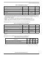
Freescale Semiconductor Technical Data Document Number: MPC603E7TEC Rev. 5, 09/2011 PowerPC 603e RISC Microprocessor Family: PID7t-603e Hardware Specifications The PowerPC™ 603e microprocessor is an implementation of the PowerPC family of reduced instruction set computing (RISC) microprocessors. In this document, the term ‘603e’ is used as an abbreviation for the PowerPC 603e microprocessor. The PowerPC 603e microprocessors are available from Freescale as MPC603e. The 603e is implemented in several semiconductor fabrication processes. Different processes may require different supply voltages and may have other electrical differences but will have the same functionality. As a technical designator to distinguish between 603e implementations in various processes, a prefix composed of the processor version register (PVR) value and a process identifier (PID) is assigned to the various implementations as shown in Table 1. This document describes the pertinent physical characteristics of the PID7t-603e from Freescale. For functional characteristics of the 603e, refer to the PowerPC 603e RISC Microprocessor User’s Manual. To locate any published errata or updates for this document, refer to the website at www.freescale.com. © Freescale Semiconductor, Inc., 2011. All rights reserved. 1. 2. 3. 4. 5. 6. 7. 8. 9. 10. Contents Overview . . . . . . . . . . . . . . . . . . . . . . . . . . . . . . . . . . . 2 Features . . . . . . . . . . . . . . . . . . . . . . . . . . . . . . . . . . . . 3 General Parameters . . . . . . . . . . . . . . . . . . . . . . . . . . . 4 Electrical and Thermal Characteristics . . . . . . . . . . . . 4 Pin Assignments . . . . . . . . . . . . . . . . . . . . . . . . . . . . 14 Pinout Listings . . . . . . . . . . . . . . . . . . . . . . . . . . . . . 15 Package Descriptions . . . . . . . . . . . . . . . . . . . . . . . . 17 System Design Information . . . . . . . . . . . . . . . . . . . . 20 Ordering Information . . . . . . . . . . . . . . . . . . . . . . . . 29 Revision History . . . . . . . . . . . . . . . . . . . . . . . . . . . . 30 Overview Table 1. PowerPC 603e Microprocessors from Freescale 1 Technical Designator Process PID6-603e 0.5 µm CMOS, 4LM 3.3 3.3 Yes MPC603E PID7v-603e 0.35 µm CMOS, 5LM 2.5 3.3 Yes XPC603P (end-of-life) PID7t-603e 0.29 µm CMOS, 5LM 2.5 3.3 Yes MPC603R Core Voltage I/O Voltage 5-Volt (V) (V) Tolerant Part Number Overview The 603e is a low-power implementation of the PowerPC microprocessor family of RISC microprocessors. The 603e implements the 32-bit portion of the PowerPC architecture specification that provides 32-bit effective addresses, integer data types of 8, 16, and 32 bits, and floating-point data types of 32 and 64 bits. For 64-bit PowerPC microprocessors, the PowerPC architecture provides 64-bit integer data types, 64-bit addressing, and other features required to complete the 64-bit architecture. The 603e provides four software controllable power-saving modes. Three of the modes (the nap, doze, and sleep) are static in nature, and progressively reduce the amount of power dissipated by the processor. The fourth is a dynamic power management mode that causes the functional units in the 603e to automatically enter a low-power mode when the functional units are idle without affecting operational performance, software execution, or any external hardware. The 603e is a superscalar processor capable of issuing and retiring as many as three instructions per clock. Instructions can execute out of order for increased performance; however, the 603e makes completion appear sequential. The 603e integrates five execution units—an integer unit (IU), a floating-point unit (FPU), a branch processing unit (BPU), a load/store unit (LSU), and a system register unit (SRU). The ability to execute five instructions in parallel and the use of simple instructions with rapid execution times yield high efficiency and throughput for 603e-based systems. Most integer instructions execute in one clock cycle. The FPU is pipelined, so a single-precision multiply-add instruction can be issued every clock cycle. The 603e provides independent on-chip, 16-Kbyte, four-way set-associative, physically addressed caches for instructions and data and on-chip instruction and data memory management units (MMUs). The MMUs contain 64-entry, two-way, set-associative data and instruction translation lookaside buffers (DTLB and ITLB) that provide support for demand-paged virtual memory address translation and variable-sized block translation. The TLBs and caches use a least-recently used (LRU) replacement algorithm. The 603e also supports block address translation through the use of two independent instruction and data block address translation (IBAT and DBAT) arrays of four entries each. Effective addresses are compared simultaneously with all four entries in the BAT array during block translation. In accordance with the PowerPC architecture, if an effective address hits in both the TLB and BAT array, the BAT translation takes priority. The 603e has a selectable 32- or 64-bit data bus and a 32-bit address bus. The 603e interface protocol allows multiple masters to compete for system resources through a central external arbiter. The 603e provides a three-state coherency protocol that supports the exclusive, modified, and invalid cache states. This protocol is a compatible subset of the MESI (modified/exclusive/shared/invalid) four-state protocol PID7t-603e Hardware Specifications, Rev. 5 2 Freescale Semiconductor Features and operates coherently in systems that contain four-state caches. The 603e supports single-beat and burst data transfers for memory accesses, and supports memory-mapped I/O. The 603e uses an advanced, 2.5/3.3-V CMOS process technology and maintains full interface compatibility with TTL devices. The PID7t-603e is offered in both PBGA and CBGA packages. The CBGA package supports speed bins of 200, 266, and 300 MHz. The PBGA package is a pin-compatible drop in replacement for the CBGA; however, this package only supports speeds up to 200 MHz. 2 Features This section summarizes features of the 603e’s implementation of the PowerPC architecture. Major features of the 603e are as follows: • High-performance, superscalar microprocessor — As many as three instructions issued and retired per clock — As many as five instructions in execution per clock — Single-cycle execution for most instructions — Pipelined FPU for all single-precision and most double-precision operations • Five independent execution units and two register files — BPU featuring static branch prediction — A 32-bit IU — Fully IEEE 754-compliant FPU for both single- and double-precision operations — LSU for data transfer between data cache and GPRs and FPRs — SRU that executes condition register (CR), special-purpose register (SPR) instructions, and integer add/compare instructions — 32 GPRs for integer operands — 32 FPRs for single- or double-precision operands • High instruction and data throughput — Zero-cycle branch capability (branch folding) — Programmable static branch prediction on unresolved conditional branches — Instruction fetch unit capable of fetching two instructions per clock from the instruction cache — A six-entry instruction queue that provides lookahead capability — Independent pipelines with feed-forwarding that reduces data dependencies in hardware — 16-Kbyte data cache—four-way, set-associative physically addressed; LRU replacement algorithm — 16-Kbyte instruction cache—four-way, set-associative physically addressed; LRU replacement algorithm — Cache write-back or write-through operation programmable on a per page or per block basis — BPU that performs CR lookahead operations — Address translation facilities for 4-Kbyte page size, variable block size, and 256-Mbyte segment size PID7t-603e Hardware Specifications, Rev. 5 Freescale Semiconductor 3 General Parameters • • • 3 — A 64-entry two-way, set-associative ITLB — A 64-entry two-way, set-associative DTLB — Four-entry data and instruction BAT arrays providing 128-Kbyte to 256-Mbyte blocks — Software table search operations and updates supported through fast trap mechanism — 52-bit virtual and 32-bit physical address Facilities for enhanced system performance — A 32- or 64-bit split-transaction external data bus with burst transfers — Support for one-level address pipelining and out-of-order bus transactions Integrated power management — Low-power 2.5/3.3-volt design — Internal processor/bus clock multiplier that provides 2:1, 2.5:1, 3:1, 3.5:1, 4:1, 4.5:1, 5:1, 5.5:1, and 6:1 ratios — Three power-saving modes: doze, nap, and sleep — Automatic dynamic power reduction when internal functional units are idle In-system testability and debugging features through JTAG boundary-scan capability General Parameters The following list provides a summary of the general parameters of the PID7t-603e: Technology 0.29 µm CMOS, five-layer metal Die size 5.65 mm x 7.7 mm (44 mm2) Transistor count 2.6 million Logic design Fully-static Package 255 ceramic ball grid array (CBGA) or 225 thin map plastic ball grid array (PBGA) Core power supply 2.5 ± 5% V dc I/O power supply 3.3 ± 5% V dc 4 Electrical and Thermal Characteristics This section provides the AC and DC electrical specifications and thermal characteristics for the PID7t-603e. 4.1 DC Electrical Characteristics The tables in this section describe the PID7t-603e DC electrical characteristics. This table provides the absolute maximum ratings. PID7t-603e Hardware Specifications, Rev. 5 4 Freescale Semiconductor Electrical and Thermal Characteristics Table 2. Absolute Maximum Ratings Characteristic Symbol Value Unit Core supply voltage Vdd –0.3 to 2.75 V PLL supply voltage AVdd –0.3 to 2.75 V I/O supply voltage OVdd –0.3 to 3.6 V Input voltage Vin –0.3 to 5.5 V Storage temperature range Tstg –55 to 150 °C Note: 1. Functional and tested operating conditions are given in Table 3. Absolute maximum ratings are stress ratings only, and functional operation at the maximums is not guaranteed. Stresses beyond those listed may affect device reliability or cause permanent damage to the device. 2. Caution: Vin must not exceed OVdd by more than 2.5 V at any time, including during power-on reset. 3. Caution: OVdd must not exceed Vdd/AVdd by more than 1.2 V at any time, including during power-on reset. 4. Caution: Vdd/AVdd must not exceed OVdd by more than 0.4 V at any time, including during power-on reset. This table provides the recommended operating conditions for the PID7t-603e. Table 3. Recommended Operating Conditions Characteristic Symbol Value Unit Core supply voltage Vdd 2.375 to 2.625 V PLL supply voltage AVdd 2.375 to 2.625 V I/O supply voltage OVdd 3.135 to 3.465 V Input voltage Vin GND to 5.5 V Die-junction temperature Tj 0 to 105 °C Note: These are the recommended and tested operating conditions. Proper device operation outside of these conditions is not guaranteed. This table provides the package thermal characteristics for the PID7t-603e. Table 4. Package Thermal Characteristics Symbol Value CBGA Value PBGA Rating Package die junction-to-case thermal resistance (typical) JC 0.095 8.0 °C/W Package die junction-to-ball thermal resistance (typical) JB 3.5 13 °C/W Characteristic Note: For more about thermal management, see Section 8, “System Design Information.” PID7t-603e Hardware Specifications, Rev. 5 Freescale Semiconductor 5 Electrical and Thermal Characteristics This table provides the DC electrical characteristics for the PID7t-603e. Table 5. DC Electrical Specifications Vdd = AVdd = 2.5 ± 5% V dc, OVdd = 3.3 ± 5% V dc, GND = 0 V dc, 0 Tj 105 °C Characteristic Symbol Min Max Unit Note Input high voltage (all inputs except SYSCLK) VIH 2.0 5.5 V — Input low voltage (all inputs except SYSCLK) VIL GND 0.8 V — SYSCLK input high voltage CVIH 2.4 5.5 V — SYSCLK input low voltage CVIL GND 0.4 V — Input leakage current, Vin = 3.465 V Iin — 30 µA 1, 2 Vin = 5.5 V Iin — 300 µA 1, 2 Hi-Z (off-state) leakage current, Vin = 3.465 V ITSI — 30 µA 1, 2 Vin = 5.5 V ITSI — 300 µA 1, 2 Output high voltage, IOH = –7 mA VOH 2.4 — V — Output low voltage, IOL = 7 mA VOL — 0.4 V — Capacitance, Vin = 0 V, f = 1 MHz (excludes TS, ABB, DBB, and ARTRY) Cin — 10.0 pF 3 Capacitance, Vin = 0 V, f = 1 MHz (for TS, ABB, DBB, and ARTRY) Cin — 15.0 pF 3 Notes: 1. Excludes test signals (LSSD_MODE, L1_TSTCLK, L2_TSTCLK, and JTAG signals). 2. The leakage is measured for nominal OVdd and Vdd or both OVdd and Vdd must vary in the same direction (for example, both OVdd and Vdd vary by either +5% or -5%). 3. Capacitance is periodically sampled rather than 100% tested. This table provides the power consumption for the PID7t-603e. Table 6. Power Consumption Processor (CPU) Frequency Unit 100 MHz 133 MHz 166 MHz 200 MHz 233 MHz 266 MHz 300 MHz Full-On Mode (DPM Enabled) Typical 1.1 1.6 2.1 2.5 3.0 3.5 4.0 W Maximum 1.6 2.4 3.2 4.0 4.6 5.3 6.0 W 0.55 0.7 0.9 1.1 1.3 1.5 1.8 W 50 60 75 85 100 120 130 mW 45 50 55 65 75 90 100 mW Doze Mode Typical Nap Mode Typical Sleep Mode Typical Sleep Mode—PLL Disabled PID7t-603e Hardware Specifications, Rev. 5 6 Freescale Semiconductor Electrical and Thermal Characteristics Table 6. Power Consumption (continued) Processor (CPU) Frequency Unit 100 MHz 133 MHz 166 MHz 200 MHz 233 MHz 266 MHz 300 MHz 40 40 40 40 40 40 40 mW Typical Sleep Mode—PLL and SYSCLK Disabled Typical 15 15 15 15 15 15 15 mW Maximum 25 25 25 25 25 80 100 mW Note: 1. These values apply for all valid PLL_CFG[0–3] settings and do not include output driver power (OVdd) or analog supply power (AVdd). OVdd power is system dependent but is typically 10% of Vdd. Worst-case AVdd = 15 mW. 2. Typical power is an average value measured at Vdd = AVdd = 2.5 V, OVdd = 3.3V, in a system executing typical applications and benchmark sequences. 3. Maximum power is measured at 2.625 V using a worst-case instruction mix. 4.2 AC Electrical Characteristics This section provides the AC electrical characteristics for the PID7t-603e. These specifications are for 200, 266, and 300 MHz processor speed grades. The processor core frequency is determined by the bus (SYSCLK) frequency and the settings of the PLL_CFG[0–3] signals. All timings are specified respective to the rising edge of SYSCLK. PLL_CFG signals should be set prior to power up and not altered afterwards. 4.2.1 Clock AC Specifications This table provides the clock AC timing specifications as defined in Figure 1. After fabrication, parts are sorted by maximum processor core frequency as shown in Section 4.2.1, “Clock AC Specifications,” and tested for conformance to the AC specifications for that frequency. Parts are sold by maximum processor core frequency; see Section 9, “Ordering Information.” Table 7. Clock AC Timing Specifications Vdd = AVdd = 2.5 ± 5% V dc, OVdd = 3.3 ± 5% V dc, GND = 0 V dc, 0 Tj 105 °C Num Characteristic 200 MHz PBGA 200 MHz CBGA 266 MHz CBGA 300 MHz CBGA Unit Note Min Max Min Max Min Max Min Max Processor frequency 100 200 80 200 150 266 180 300 MHz 1, 6 VCO frequency 300 400 300 400 300 532 360 600 MHz 1 SYSCLK frequency 25 66.67 25 66.67 25 75 33.3 75 MHz 1 1 SYSCLK cycle time 13.3 40 13.3 40 13.3 40 13.3 30 ns 2, 3 SYSCLK rise and fall time — 2.0 — 2.0 — 2.0 — 2.0 ns 2 4 SYSCLK duty cycle measured at 1.4 V 40.0 60.0 40.0 60.0 40.0 60.0 40.0 60.0 % 3 PID7t-603e Hardware Specifications, Rev. 5 Freescale Semiconductor 7 Electrical and Thermal Characteristics Table 7. Clock AC Timing Specifications (continued) Vdd = AVdd = 2.5 ± 5% V dc, OVdd = 3.3 ± 5% V dc, GND = 0 V dc, 0 Tj 105 °C Num 200 MHz PBGA Characteristic 200 MHz CBGA 266 MHz CBGA 300 MHz CBGA Unit Note Min Max Min Max Min Max Min Max SYSCLK jitter — ±150 — ±150 — ±150 — ±150 ps 4 PID7t internal PLL-relock time — 100 — 100 — 100 — 100 s 3, 5 Note: 1. Caution: The SYSCLK frequency and PLL_CFG[0–3] settings must be chosen such that the resulting SYSCLK (bus) frequency, CPU (core) frequency, and PLL (VCO) frequency do not exceed their respective maximum or minimum operating frequencies. Refer to the PLL_CFG[0–3] signal description in Section 8, “System Design Information,” for valid PLL_CFG[0–3] settings. 2. Rise and fall times for the SYSCLK input are measured from 0.4 V to 2.4 V. 3. Timing is guaranteed by design and characterization, and is not tested. 4. Cycle-to-cycle jitter, and is guaranteed by design. The total input jitter (short term and long term combined) must be under ±150 ps to guarantee the input/output timing of Section 4.2.2, “Input AC Specifications,” and Section 4.2.3, “Output AC Specifications.” 5. Relock timing is guaranteed by design and characterization, and is not tested. PLL-relock time is the maximum time required for PLL lock after a stable Vdd, OVdd, AVdd, and SYSCLK are reached during the power-on reset sequence. This specification also applies when the PLL has been disabled and subsequently re-enabled during sleep mode. Also note that HRESET must be held asserted for a minimum of 255 bus clocks after the PLL-relock time (100 s) during the power-on reset sequence. 6. Operation below 150 MHz is supported only by PLL_CFG[0–3] = 0b0101. Refer to Section 8.1, “PLL Configuration” for additional information. This figure provides the SYSCLK input timing diagram. 1 4 4 2 3 CVih SYSCLK VM VM VM CVil VM = Midpoint Voltage (1.4 V) Figure 1. SYSCLK Input Timing Diagram 4.2.2 Input AC Specifications This table provides the input AC timing specifications for the PID7t-603e as defined in Figure 2 and Figure 3. PID7t-603e Hardware Specifications, Rev. 5 8 Freescale Semiconductor Electrical and Thermal Characteristics Table 8. Input AC Timing Specifications1 Vdd = AVdd = 2.5 ± 5% V dc, OVdd = 3.3 ± 5% V dc, GND = 0 V dc, 0 Tj 105° C 200, 266, 300 MHz Num Characteristic Min Max Unit Notes 10a Address/data/transfer attribute inputs valid to SYSCLK (input setup) 2.5 — ns 2 10b All other inputs valid to SYSCLK (input setup) 3.5 — ns 3 10c Mode select inputs valid to HRESET (input setup) (for DRTRY, QACK and TLBISYNC) 8 — tsysclk 4, 5, 6, 7 11a SYSCLK to address/data/transfer attribute inputs invalid (input hold) 1.0 — ns 2 11b SYSCLK to all other inputs invalid (input hold) 1.0 — ns 3 11c HRESET to mode select inputs invalid (input hold) (for DRTRY, QACK, and TLBISYNC) 0 — ns 4, 6, 7 Note: 1. Input specifications are measured from the TTL level (0.8 or 2.0 V) of the signal in question to the 1.4 V of the rising edge of the input SYSCLK. Input and output timings are measured at the pin. 2. Address/data/transfer attribute input signals are composed of the following—A[0–31], AP[0–3], TT[0–4], TC[0–1], TBST, TSIZ[0–2], GBL, DH[0–31], DL[0–31], DP[0–7]. 3. All other input signals are composed of the following—TS, ABB, DBB, ARTRY, BG, AACK, DBG, DBWO, TA, DRTRY, TEA, DBDIS, HRESET, SRESET, INT, SMI, MCP, TBEN, QACK, TLBISYNC. 4. The setup and hold time is with respect to the rising edge of HRESET (see Figure 3). 5. tsysclk is the period of the external clock (SYSCLK) in nanoseconds (ns). The numbers given in the table must be multiplied by the period of SYSCLK to compute the actual time duration (in nanoseconds) of the parameter in question. 6. These values are guaranteed by design, and are not tested. 7. This specification is for configuration mode only. Also note that HRESET must be held asserted for a minimum of 255 bus clocks after the PLL-relock time during the power-on reset sequence. This figure provides the input timing diagram for the PID7t-603e. VM SYSCLK 10a 10b 11a 11b ALL INPUTS VM = Midpoint Voltage (1.4 V) Figure 2. Input Timing Diagram PID7t-603e Hardware Specifications, Rev. 5 Freescale Semiconductor 9 Electrical and Thermal Characteristics This figure provides the mode select input timing diagram for the PID7t-603e. VM HRESET 10c 11c MODE PINS VM = Midpoint Voltage (1.4 V) Figure 3. Mode Select Input Timing Diagram 4.2.3 Output AC Specifications This table provides the output AC timing specifications for the PID7t-603e as defined in Figure 4. Table 9. Output AC Timing Specifications1 Vdd = AVdd = 2.5 5% V dc, OVdd = 3.3 ± 5%, GND = 0 V dc, 0 Tj 105 °C, CL = 50 pF (unless otherwise noted) 200, 266, 300 MHz Num Characteristic Min Max Unit Note 12 SYSCLK to output driven (output enable time) 1.0 — ns — 13a SYSCLK to output valid (5.5 V to 0.8 V—TS, ABB, ARTRY, DBB) — 9.0 ns 3 13b SYSCLK to output valid (TS, ABB, ARTRY, DBB) — 8.0 ns 5 14a SYSCLK to output valid (5.5 V to 0.8 V—all except TS, ABB, ARTRY, DBB) — 11.0 ns 3 14b SYSCLK to output valid (all except TS, ABB, ARTRY, DBB) — 9.0 ns 5 15 SYSCLK to output invalid (output hold) 1.0 — ns 2 16 SYSCLK to output high impedance (all except ARTRY, ABB, DBB) — 8.0 ns — 17 SYSCLK to ABB, DBB, high impedance after precharge — 1.0 tsysclk 4, 6 18 SYSCLK to ARTRY high impedance before precharge — 7.5 ns — 19 SYSCLK to ARTRY precharge enable 0.2 * tsysclk + 1.0 — ns 2, 4, 7 20 Maximum delay to ARTRY precharge — 1.0 tsysclk 4, 7 21 SYSCLK to ARTRY high impedance after precharge — 2.0 tsysclk 5, 7 PID7t-603e Hardware Specifications, Rev. 5 10 Freescale Semiconductor Electrical and Thermal Characteristics Table 9. Output AC Timing Specifications1 (continued) Vdd = AVdd = 2.5 5% V dc, OVdd = 3.3 ± 5%, GND = 0 V dc, 0 Tj 105 °C, CL = 50 pF (unless otherwise noted) 200, 266, 300 MHz Num Characteristic Unit Min Note Max Note: 1. All output specifications are measured from the 1.4 V of the rising edge of SYSCLK to the TTL level (0.8 V or 2.0 V) of the signal in question. Both input and output timings are measured at the pin (see Figure 4). 2. This minimum parameter assumes CL = 0 pF. 3. SYSCLK to output valid (5.5 V to 0.8 V) includes the extra delay associated with discharging the external voltage from 5.5 V to 0.8 V instead of from Vdd to 0.8 V (5-V CMOS levels instead of 3.3-V CMOS levels). 4. tsysclk is the period of the external bus clock (SYSCLK) in nanoseconds (ns). The numbers given in the table must be multiplied by the period of SYSCLK to compute the actual time duration (in nanoseconds) of the parameter in question. 5. Output signal transitions from GND to 2.0 V or Vdd to 0.8 V. 6. Nominal precharge width for ABB and DBB is 0.5 tsysclk. 7. Nominal precharge width for ARTRY is 1.0 tsysclk. This figure provides the output timing diagram for the PID7t-603e. VM VM VM SYSCLK 14 15 16 12 ALL OUTPUTS (Except TS, ABB, DBB, ARTRY) 15 13 13 16 TS 17 ABB, DBB 21 20 19 18 ARTRY VM = Midpoint Voltage (1.4 V) Figure 4. Output Timing Diagram 4.3 JTAG AC Timing Specifications This table provides the JTAG AC timing specifications as defined in Figure 5–Figure 8. PID7t-603e Hardware Specifications, Rev. 5 Freescale Semiconductor 11 Electrical and Thermal Characteristics Table 10. JTAG AC Timing Specifications Vdd = AVdd = 2.5 ± 5% V dc, OVdd = 3.3 ± 5%, GND = 0 V dc, 0 Tj 105° C, CL = 50 pF Num Characteristic TCK frequency of operation Min Max Unit Note 0 16 MHz — 62.5 — ns — 1 TCK cycle time 2 TCK clock pulse width measured at 1.4 V 25 — ns — 3 TCK rise and fall times 0 3 ns — 4 TRST setup time to TCK rising edge 13 — ns 1 5 TRST assert time 40 — ns — 6 Boundary scan input data setup time 6 — ns 2 7 Boundary scan input data hold time 27 — ns 2 8 TCK to output data valid 4 25 ns 3 9 TCK to output high impedance 3 24 ns 3 10 TMS, TDI data setup time 0 — ns — 11 TMS, TDI data hold time 25 — ns — 12 TCK to TDO data valid 4 24 ns — 13 TCK to TDO high impedance 3 15 ns — Note: 1. TRST is an asynchronous signal. The setup time is for test purposes only. 2. Non-test signal input timing with respect to TCK. 3. Non-test signal output timing with respect to TCK. This figure provides the JTAG clock input timing diagram. 1 2 2 VM TCK 3 VM VM 3 VM = Midpoint Voltage (1.4 V) Figure 5. JTAG Clock Input Timing Diagram PID7t-603e Hardware Specifications, Rev. 5 12 Freescale Semiconductor Electrical and Thermal Characteristics This figure provides the TRST timing diagram. VM TCK 4 TRST 5 Figure 6. TRST Timing Diagram This figure provides the boundary-scan timing diagram. TCK VM VM 6 Data Inputs 7 Input Data Valid 8 Data Outputs Output Data Valid 9 Data Outputs 8 Data Outputs Output Data Valid Figure 7. Boundary-Scan Timing Diagram This figure provides the test access port timing diagram. TCK VM VM 10 TDI, TMS 11 Input Data Valid 12 TDO Output Data Valid 13 TDO 12 TDO Output Data Valid Figure 8. Test Access Port Timing Diagram PID7t-603e Hardware Specifications, Rev. 5 Freescale Semiconductor 13 Pin Assignments 5 Pin Assignments Part A of Figure 9 shows the pinout of the CBGA package as viewed from the top surface. Part B shows the side profile of the CBGA package to indicate the direction of the top surface view. The PBGA package has an identical pinout. Part C shows the side profile of the PBGA package to indicate the direction of the top surface view. Part A 01 02 03 04 05 06 07 08 09 10 11 12 13 14 15 16 A B C D E F G H J K L M N P R T Not to Scale Part B Substrate Assembly View Encapsulant Die PID7t-603e Hardware Specifications, Rev. 5 14 Freescale Semiconductor Pinout Listings Part C Substrate Assembly View Mold Compound Die Figure 9. Pinout of the CBGA and PBGA Packages as Viewed from the Top Surface 6 Pinout Listings This table provides the pinout listing for the 603e CBGA and PBGA packages. Table 11. Pinout Listing for the 255-Pin CBGA and PBGA Packages Signal Name Pin Number Active I/O A[0–31] C16, E04, D13, F02, D14, G01, D15, E02, D16, D04, E13, GO2, E15, H01, E16, H02, F13, J01, F14, J02, F15, H03, F16, F04, G13, K01, G15, K02, H16, M01, J15, P01 High I/O AACK L02 Low I ABB K04 Low I/O AP[0–3] C01, B04, B03, B02 High I/O APE A04 Low O ARTRY J04 Low I/O AVDD A10 — — BG L01 Low I BR B06 Low O CI E01 Low O CKSTP_IN D08 Low I CKSTP_OUT A06 Low O CLK_OUT D07 — O CSE[0–1] B01, B05 High O DBB J14 Low I/O DBG N01 Low I DBDIS H15 Low I DBWO G04 Low I DH[0–31] P14, T16, R15, T15, R13, R12, P11, N11, R11,T12, T11, R10, P09, N09, T10, R09, T09, P08, N08, R08, T08, N07, R07, T07, P06, N06, R06, T06, R05, N05, T05, T04 High I/O DL[0–31] K13, K15, K16, L16, L15, L13, L14, M16, M15, M13, N16, N15, N13, N14, P16, P15, R16, R14, T14, N10, P13, N12, T13, P03, N03, N04, R03, T01, T02, P04, T03, R04 High I/O PID7t-603e Hardware Specifications, Rev. 5 Freescale Semiconductor 15 Pinout Listings Table 11. Pinout Listing for the 255-Pin CBGA and PBGA Packages (continued) Signal Name Pin Number Active I/O DP[0–7] M02, L03, N02, L04, R01, P02, M04, R02 High I/O DPE A05 Low O DRTRY G16 Low I GBL F01 Low I/O GND C05, C12, E03, E06, E08, E09, E11, E14, F05, F07, F10, F12, G06, G08, G09, G11, H05, H07, H10, H12, J05, J07, J10, J12, K06, K08, K09, K11, L05, L07, L10, L12, M03, M06, M08, M09, M11, M14, P05, P12 — — HRESET A07 Low I INT B15 Low I 1 D11 — I L2_TSTCLK 1 D12 — I LSSD_MODE 1 B10 Low I MCP C13 Low I NC (No-Connect) B07, B08, C03, C06, C08, D05, D06, H04, J16 — — OVDD C07, E05, E07, E10, E12, G03, G05, G12, G14, K03, K05, K12, K14, M05, M07, M10, M12, P07, P10 — — PLL_CFG[0–3] A08, B09, A09, D09 High I QACK D03 Low I QREQ J03 Low O RSRV D01 Low O SMI A16 Low I SRESET B14 Low I SYSCLK C09 — I TA H14 Low I TBEN C02 High I TBST A14 Low I/O TC[0–1] A02, A03 High O TCK C11 — I TDI A11 High I TDO A12 High O TEA H13 Low I TLBISYNC C04 Low I TMS B11 High I TRST C10 Low I L1_TSTCLK PID7t-603e Hardware Specifications, Rev. 5 16 Freescale Semiconductor Package Descriptions Table 11. Pinout Listing for the 255-Pin CBGA and PBGA Packages (continued) Signal Name Pin Number Active I/O TS J13 Low I/O TSIZ[0–2] A13, D10, B12 High O TT[0–4] B13, A15, B16, C14, C15 High I/O WT D02 Low O VDD 2 F06, F08, F09, F11, G07, G10, H06, H08, H09, H11, J06, J08, J09, J11, K07, K10, L06, L08, L09, L11 — — VOLTDETGND 3 F03 Low O Note: 1. These are test signals for factory use only and must be pulled up to OVdd for normal machine operation. 2. OVdd inputs supply power to the I/O drivers and Vdd inputs supply power to the processor core. 3. NC (no-connect) in the PID6-603e; internally tied to GND in the PID7v-603e and PID7t-603e CBGA and PBGA package to indicate to the power supply that a low-voltage processor is present. 7 Package Descriptions The following sections provide the CBGA and PBGA package parameters and the mechanical dimensions for the 603e. 7.1 CBGA Package Description The following sections provide the package parameters and mechanical dimensions for the CBGA package. 7.1.1 Package Parameters The package parameters are as provided in the following list. The package type is 21 mm x 21 mm, 255-lead ceramic ball grid array (CBGA). Package outline 21 mm x 21 mm Interconnects 255 Pitch 1.27 mm (50 mil) Package height Minimum: 2.45 mm Maximum: 3.00 mm Ball diameter 0.89 mm (35 mil) Maximum heat sink force 10 lbs PID7t-603e Hardware Specifications, Rev. 5 Freescale Semiconductor 17 Package Descriptions 7.1.2 Mechanical Dimensions of the CBGA Package This figure provides the mechanical dimensions and bottom surface nomenclature of the CBGA package. 2X 0.200 A A1 CORNER –E– –T– 0.150 T B P 2X NOTES: 1. DIMENSIONING AND TOLERANCING PER ANSI Y14.5M, 1982. 2. CONTROLLING DIMENSION: MILLIMETER. 0.200 N –F– MILLIMETERS INCHES DIM MIN 1 2 3 4 5 6 7 8 9 10 11 12 13 14 15 16 T R P N M L K J H G F E D C B A K G A 21.000 BSC B 21.000 BSC H MIN MAX 0.827 BSC 0.827 BSC C 2.450 3.000 0.097 0.118 D 0.820 0.930 0.032 0.036 G C MAX H K 1.270 BSC 0.790 0.990 0.635 BSC 0.050 BSC 0.031 0.039 0.025 BSC N 5.000 16.000 0.197 0.630 P 5.000 16.000 0.197 0.630 K 255X D 0.300 S T E 0.150 S T S F S Figure 10. Mechanical Dimensions and Bottom Surface Nomenclature of the CBGA Package 7.2 PBGA Package Description The following sections provide the package parameters and mechanical dimensions. 7.2.1 Package Parameters The package type is 23 mm x 23 mm, 255-lead plastic ball grid array (PBGA). Package outline 23 mm x 23 mm PID7t-603e Hardware Specifications, Rev. 5 18 Freescale Semiconductor Package Descriptions Interconnects Pitch Package height Ball diameter Maximum heat sink force 7.2.2 255 1.27 mm (50 mil) Minimum: 2.1 mm; Maximum: 2.6 mm 0.76 mm (30 mil) 5 lbs Mechanical Dimensions of the PBGA Package This figure shows the non-JEDEC package mechanical dimensions and bottom surface nomenclature. NOTES: 1. DIMENSIONING AND TOLERANCING PER ASME Y14.5M, 1994. 2. DIMENSIONS IN MILLIMETERS. 3. DIMENSION b IS MEASURED AT THE MAXIMUM SOLDER BALL DIAMETER, PARALLEL TO PRIMARY DATUM C. 4. PRIMARY DATUM C AND THE SEATING PLANE ARE D A 0.20 C 256X D2 0.35 C E DIM A A1 A2 A3 b D D1 D2 E E1 E2 e E2 4X 0.20 A2 A3 TOP VIEW MILLIMETERS MIN MAX 2.10 2.60 0.50 0.70 1.10 1.20 0.50 0.70 0.60 0.90 23.00 BSC 19.05 REF 19.40 19.60 23.00 BSC 19.05 REF 19.40 19.60 1.27 BSC B A1 A (D1) 15X C e SEATING PLANE T R P N M L K J H G F E D C B A SIDE VIEW 15X e (E1) 4X e /2 1 2 3 4 5 6 7 8 9 10 11 12 13 14 15 16 256X BOTTOM VIEW b 0.30 M C A B 0.15 M C Figure 11. Package Dimensions for the Plastic Ball Grid Array (PBGA)—non-JEDEC Standard Note that Table 11 lists the pinout to this non-JEDEC standard in order to be consistent with the CBGA pinout. This figure shows the JEDEC package dimensions of the PBGA package. PID7t-603e Hardware Specifications, Rev. 5 Freescale Semiconductor 19 System Design Information NOTES: 1. DIMENSIONING AND TOLERANCING PER ASME Y14.5M, 1994. 2. DIMENSIONS IN MILLIMETERS. 3. DIMENSION b IS MEASURED AT THE MAXIMUM SOLDER BALL DIAMETER, PARALLEL TO PRIMARY DATUM C. 4. PRIMARY DATUM C AND THE SEATING PLANE ARE D A 0.20 C 256X D2 0.35 C E DIM A A1 A2 A3 b D D1 D2 E E1 E2 e E2 4X 0.20 A2 A3 TOP VIEW MILLIMETERS MIN MAX 2.10 2.60 0.50 0.70 1.10 1.20 0.50 0.70 0.60 0.90 23.00 BSC 19.05 REF 19.40 19.60 23.00 BSC 19.05 REF 19.40 19.60 1.27 BSC B A1 A (D1) 15X C e SEATING PLANE U T R P N M L K J H G F E D C B SIDE VIEW 15X e (E1) 4X e /2 2 3 4 5 6 7 8 9 10 11 12 13 14 15 16 17 256X BOTTOM VIEW b 0.30 M C A B 0.15 M C CASE 1167-01 Figure 12. Package Dimensions for the Plastic Ball Grid Array (PBGA)—JEDEC Standard Note that the pin numberings shown in Figure 12 do not match Table 11; the pinout of the non-JEDEC standard package (and the CBGA pinout) is shown in Figure 11. Note that Figure 11 should be used in conjunction with Table 11 for the complete pinout description. 8 System Design Information This section provides electrical and thermal design recommendations for successful application of 603e. PID7t-603e Hardware Specifications, Rev. 5 20 Freescale Semiconductor System Design Information 8.1 PLL Configuration The 603e PLL is configured by the PLL_CFG[0–3] signals. For a given SYSCLK (bus) frequency, the PLL configuration signals set the internal CPU and VCO frequency of operation. The PLL configuration for the PID7t-603e is shown in this table for nominal frequencies. Table 12. PLL Configuration CPU Frequency in MHz (VCO Frequency in MHz) PLL_CFG[0:3] Bus-to-Core Core-to-VCO Multiplier Multiplier Bus 25 MHz Bus Bus Bus Bus Bus Bus 33.33 MHz 40 MHz 50 MHz 60 MHz 66.67 MHz 75 MHz 0100 2x 2x — — — — — — 150 (300) 0101 2x 4x — — 804 (320) 100 (400) 120 (480) 133 (532) 150 (600) 0110 2.5x 2x — — — — 150 (300) 166 (333) 187 (375) 1000 3x 2x — — — 150 (300) 180 (360) 200 (400) 225 (450) 1110 3.5x 2x — — — 175 (350) 210 (420) 233 (466) 263 (525) 1010 4x 2x — — 160 (320) 200 (400) 240 (480) 267 (533) 300 (600) 0111 4.5x 2x — 150 (300) 180 (360) 225 (450) 270 (540) 300 (600) — 1011 5x 2x — 166 (333) 200 (400) 250 (500) 300 (600) — — 1001 5.5x 2x — 183 (366) 220 (440) 275 (550) — — — 1101 6x 2x 150 (300) 200 (400) 240 (480) 300 (600) — — — 0011 PLL bypass 1111 Clock off Note: 1. Some PLL configurations may select bus, CPU, or VCO frequencies which are not supported; see Section 4.2.1, “Clock AC Specifications,” for valid SYSCLK and VCO frequencies. 2. In PLL-bypass mode, the SYSCLK input signal clocks the internal processor directly, the PLL is disabled, and the bus mode is set for 1:1 mode operation. This mode is intended for factory use only. Note: The AC timing specifications given in this document do not apply in PLL-bypass mode. 3. In clock-off mode, no clocking occurs inside the 603e regardless of the SYSCLK input. 4. 80 MHz operation is not supported for the PBGA package (see Table 7). 8.2 PLL Power Supply Filtering The AVdd power signal is provided on the 603e to provide power to the clock generation phase-locked loop. To ensure stability of the internal clock, the power supplied to the AVdd input signal should be filtered PID7t-603e Hardware Specifications, Rev. 5 Freescale Semiconductor 21 System Design Information using a circuit similar to the one shown in Figure 13. The circuit should be placed as close as possible to the AVdd pin to ensure it filters out as much noise as possible. The 0.1 µF capacitor should be closest to the AVdd pin, followed by the 10 µF capacitor, and finally the 10 resistor to Vdd. These traces should be kept short and direct. 10 Vdd AVdd 0.1 µF 10 µF GND Figure 13. PLL Power Supply Filter Circuit 8.3 Decoupling Recommendations Due to the 603e’s dynamic power management feature, large address, data buses, and high-operating frequencies, it can generate transient power surges and high-frequency noise in its power supply, especially while driving large capacitive loads. This noise must be prevented from reaching other components in the 603e system. It requires a clean, tightly regulated source of power. Therefore, it is recommended that the system designer places at least one decoupling capacitor at each Vdd and OVdd pin of the 603e. It is also recommended that these decoupling capacitors receive their power from separate Vdd, OVdd, and GND power planes in the PCB, utilizing short traces to minimize inductance. These capacitors should vary in value from 220 pF to 10 F to provide both high- and low-frequency filtering, and should be placed as close as possible to their associated Vdd or OVdd pin. Suggested values for the Vdd pins are: 220 pF (ceramic), 0.01 µF (ceramic), and 0.1 µF (ceramic). Suggested values for the OVdd pins are: 0.01 µF (ceramic), 0.1 µF (ceramic), and 10 µF (tantalum). Only SMT capacitors should be used to minimize lead inductance. In addition, it is recommended that there be several bulk storage capacitors distributed around the PCB, feeding the Vdd and OVdd planes, to enable quick recharging of the smaller chip capacitors. These bulk capacitors should also have a low ESR (equivalent series resistance) rating to ensure the quick response time necessary. They should also be connected to the power and ground planes through two vias to minimize inductance. Suggested bulk capacitors—100 µF (AVX TPS tantalum) or 330 µF (AVX TPS tantalum). 8.4 Connection Recommendations To ensure reliable operation, it is highly recommended to connect unused inputs to an appropriate signal level. Unused active low inputs should be tied to Vdd. Unused active high inputs should be connected to GND. All NC (no-connect) signals must remain unconnected. Power and ground connections must be made to all external Vdd, OVdd, and GND pins of the 603e. PID7t-603e Hardware Specifications, Rev. 5 22 Freescale Semiconductor System Design Information 8.5 Pull-up Resistor Requirements The 603e requires high-resistive (weak: 10 K) pull-up resistors on several control signals of the bus interface to maintain the control signals in the negated state after they have been actively negated and released by the 603e or other bus master. These signals are: TS, ABB, DBB, and ARTRY. In addition, the 603e has three open-drain style outputs that require pull-up resistors (weak or stronger: 4.7 K–10 K) if they are used by the system. These signals are: APE, DPE, and CKSTP_OUT. During inactive periods on the bus, the address and transfer attributes on the bus are not driven by any master and may float in the high-impedance state for relatively long periods of time. Since the 603e must continually monitor these signals for snooping, this float condition may cause excessive power draw by the input receivers on the 603e. It is recommended that these signals be pulled up through weak (10 K) pull-up resistors or restored in some manner by the system. The snooped address and transfer attribute inputs are—A[0–31], AP[0–3], TT[0–4], TBST, and GBL. The data bus input receivers are normally turned off when no read operation is in progress and do not require pull-up resistors on the data bus. 8.6 Thermal Management Information This section provides thermal management information for the CBGA and PBGA packages for air-cooled applications. Proper thermal control design is primarily dependent upon the system-level design—the heat sink, airflow and thermal interface material. This figure shows the upper and lower limits of the die junction-to-ambient thermal resistance for both package styles. The lower limit is shown for the case of a densely populated PCB with high thermal loading of adjacent and neighboring components. PID7t-603e Hardware Specifications, Rev. 5 Freescale Semiconductor 23 System Design Information . 40 35 30 25 20 15 10 Ty pical Upp er Limit Ty pical Low er Limit 5 0 0 0.5 1 1.5 2 Airf low Velocit y (m / s) Figure 14. Typical Die Junction-to-Ambient Thermal Resistance (21 mm CBGA and 23 mm WB-PBGA) To reduce the die-junction temperature, heat sinks may be attached to the package by several methods—adhesive, spring clip to holes in the printed-circuit board or package, and mounting clip and screw assembly (both CBGA and PGBA packages); see Figure 15. CAUTION While choosing a heat sink attachment method, any attachment mechanism should not degrade the package structural integrity and/or the package-to-board interconnect reliability. For additional general information, see this paper—Investigation of Heat Sink Attach Methodologies and the Effects on Package Structural Integrity and Interconnect Reliability. PID7t-603e Hardware Specifications, Rev. 5 24 Freescale Semiconductor System Design Information CBGA Package Heat Sink Heat Sink Clip Adhesive or Thermal Interface Material Printed-Circuit Board Option PBGA Package Heat Sink Heat Sink Clip Adhesive or Thermal Interface Material Printed-Circuit Board Option Figure 15. Package Exploded Cross-Sectional View with Heat Sink The board designer can choose between several types of commercially available heat sinks to place on the 603e. Ultimately, the final selection of an appropriate heat sink depends on many factors, such as thermal performance at a given air velocity, spatial volume, mass, attachment method, assembly, and cost. PID7t-603e Hardware Specifications, Rev. 5 Freescale Semiconductor 25 System Design Information 8.6.1 Internal Package Conduction Resistance For this packaging technology, the intrinsic thermal conduction resistance (as shown in Table 3) versus the external thermal resistance paths are shown in this figure for a package with an attached heat sink mounted to a PCB. External Resistance Radiation Convection Heat Sink Thermal Interface Material Die/Package Die Junction Package/Leads Internal Resistance Printed-Circuit Board Radiation Convection External Resistance (Note the internal versus external package resistance) Figure 16. Package with Heat Sink Mounted to a Printed-Circuit Board 8.6.2 Thermal Interface Materials A thermal interface material is recommended at the package lid-to-heat sink interface to minimize the thermal contact resistance. For those applications where the heat sink is attached by spring clip mechanism, as shown in Figure 17. The thermal performance of three thin-sheet thermal-interface materials (silicone, graphite/oil, floroether oil), a bare joint, and a joint with thermal grease as a function of contact pressure. As shown, the performance of these thermal interface materials improves with increasing contact pressure. The use of thermal grease significantly reduces the interface thermal resistance. That is, the bare joint results in a thermal resistance approximately seven times greater than the thermal grease joint. Therefore, the synthetic grease offers the best thermal performance, considering the low-interface pressure. Of course, the selection of any thermal interface material depends on many factors—thermal performance requirements, manufacturability, service temperature, dielectric properties, cost, etc. PID7t-603e Hardware Specifications, Rev. 5 26 Freescale Semiconductor System Design Information Silicone Sheet (0.006 inch) Bare Joint Floroether Oil Sheet (0.007 inch) Graphite/Oil Sheet (0.005 inch) Synthetic Grease Specific Thermal Resistance (Kin2/W) 2 1.5 1 0.5 0 0 10 20 30 40 50 60 70 80 Contact Pressure (psi) Figure 17. Thermal Performance of Select Thermal Interface Material The board designer can choose between several types of thermal interface. Heat sink adhesive materials should be selected based upon high conductivity, yet adequate mechanical strength to meet equipment shock/vibration requirements. 8.6.3 Heat Sink Selection Example For preliminary heat sink sizing, the die-junction temperature can be expressed as follows: Tj = Ta + Tr + (jc + int + sa) * Pd Eqn. 1 where: Tj is the die-junction temperature Ta is the inlet cabinet ambient temperature Tr is the air temperature rise within the computer cabinet jc is the die junction-to-case thermal resistance int is the adhesive or interface material thermal resistance sa is the heat sink base-to-ambient thermal resistance Pd is the power dissipated by the device PID7t-603e Hardware Specifications, Rev. 5 Freescale Semiconductor 27 System Design Information During operation the die-junction temperatures (Tj) should be maintained less than the value specified in Table 3. The temperature of the air cooling the component greatly depends upon the ambient inlet air temperature and the air temperature rise within the electronic cabinet. An electronic cabinet inlet-air temperature (Ta) may range from 30 to 40 °C. The air temperature rise within a cabinet (Tr) may be in the range of 5 to 10 °C. The thermal resistance of the thermal interface material (int) is typically about 1 °C/W. Assuming a Ta of 30 °C, a Tr of 5 °C a CBGA package jc = 0.095, and a power consumption (Pd) of 3.0 Watts, the following expression for Tj is obtained: Die-junction temperature: Tj = 30 °C + 5 °C + (0.095 °C/W + 1.0 °C/W + Rsa) * 3.0 W. For example, the heat sink-to-ambient thermal resistance (Rsa) versus airflow velocity is shown in this figure. 8 Example: Pin-fin Heat Sink (25 x 28 x 15 mm) Heat Sink Thermal Resistance (ºC/W) 7 6 5 4 3 2 1 0 0.5 1 1.5 2 2.5 3 3.5 Approach Air Velocity (m/s) Figure 18. Example of Heat Sink-to-Ambient Thermal Resistance Versus Airflow Velocity Assuming an air velocity of 0.5 m/s, we have an effective Rsa of 7 °C/W, thus Tj = 30°C + 5°C + (0.095 °C/W +1.0 °C/W + 7 °C/W) * 3.0 W, Eqn. 2 resulting in a die-junction temperature of approximately 60 °C which is well within the maximum operating temperature of the component. For a PBGA package, and assuming a Ta of 30 °C, a Tr of 5 °C a PBGA package jc = 8, and a power consumption (Pd) of 3.0 Watts, the following expression for die-junction temperature, Tj, is obtained as: Tj = 30 °C + 5 °C + (8 °C/W + 1.0 °C/W + Rsa) * 3.0 W Eqn. 3 Assuming an air velocity of 0.5 m/s, we have an effective Rsa of 7 °C/W, thus PID7t-603e Hardware Specifications, Rev. 5 28 Freescale Semiconductor Ordering Information Tj = 30°C + 5°C + (8 °C/W +1.0 °C/W + 7 °C/W) * 3.0 W, Eqn. 4 resulting in a die-junction temperature of approximately 83 °C that is well within the maximum operating temperature of the component. Commercially available heat sinks have different heat sink-to-ambient thermal resistances, and may or may not need air flow. Though the die junction-to-ambient and the heat sink-to-ambient thermal resistances are a common figure-of-merit used for comparing the thermal performance of various microelectronic packaging technologies, one should exercise caution when only using this metric in determining thermal management because no single parameter can adequately describe three-dimensional heat flow. The final die-junction operating temperature is not only a function of the component-level thermal resistance, but the system-level design and its operating conditions. In addition to the component’s power consumption, a number of factors affect the final operating die-junction temperature—airflow, board population (local heat flux of adjacent components), heat sink efficiency, heat sink attach, heat sink placement, next-level interconnect technology, system air temperature rise, altitude, etc. Due to the complexity and the many variations of system-level boundary conditions for today’s microelectronic equipment, the combined effects of the heat transfer mechanisms (radiation, convection, and conduction) may vary widely. For these reasons, we recommend using conjugate heat transfer models for the board, as well as, system-level designs. To expedite system-level thermal analysis, several “compact” thermal-package models are available within FLOTHERM®. These are available upon request. 9 Ordering Information This figure provides the part numbering nomenclature for the PID7t-603e. Note that the individual part numbers correspond to a maximum processor core frequency. For available frequencies, contact your local Freescale sales office. In addition to the processor frequency, the part numbering scheme also consists of a part modifier and application modifier. The part modifier indicates any enhancement(s) in the part from the original design. The application modifier may specify special bus frequencies or application conditions. Each part number also contains a revision code. This refers to the die mask revision number and is specified in the part numbering scheme for identification purposes only. MPC 603 R RX XXX X X Product Code Revision Level (Contact Freescale Sales Office) Part Identifier Part Modifier (R = Remapped, Enhanced, Low-Voltage) Package (RX = CBGA without Lid) (ZT = PBGA Package) (VG = Polymer Core CBGA without Lid) Application Modifier (L = Any Valid PLL Configuration) (T = Extended Termperature Range) Processor Frequency Figure 19. Part Number Key PID7t-603e Hardware Specifications, Rev. 5 Freescale Semiconductor 29 Revision History 10 Revision History This table summarizes revision history for this document. Table 13. Document Revision History Rev. Number Date Substantive Change(s) 5 9/2011 • Updated to new Freescale template. • Added package info, VG = Polymer Core CBGA without Lid on Figure 19. • Deleted thermal heat sink and thermal interface vendor details from 8.6/-23 and 8.6.2/-26. PID7t-603e Hardware Specifications, Rev. 5 30 Freescale Semiconductor How to Reach Us: Home Page: www.freescale.com email: [email protected] USA/Europe or Locations Not Listed: Freescale Semiconductor Technical Information Center, CH370 1300 N. Alma School Road Chandler, Arizona 85224 1-800-521-6274 480-768-2130 [email protected] Europe, Middle East, and Africa: Freescale Halbleiter Deutschland GmbH Technical Information Center Schatzbogen 7 81829 Muenchen, Germany +44 1296 380 456 (English) +46 8 52200080 (English) +49 89 92103 559 (German) +33 1 69 35 48 48 (French) [email protected] Japan: Freescale Semiconductor Japan Ltd. Headquarters ARCO Tower 15F 1-8-1, Shimo-Meguro, Meguro-ku Tokyo 153-0064, Japan 0120 191014 +81 3 5437 9125 [email protected] Asia/Pacific: Freescale Semiconductor Hong Kong Ltd. Technical Information Center 2 Dai King Street Tai Po Industrial Estate, Tai Po, N.T., Hong Kong +800 2666 8080 [email protected] For Literature Requests Only: Freescale Semiconductor Literature Distribution Center P.O. Box 5405 Denver, Colorado 80217 1-800-441-2447 303-675-2140 Fax: 303-675-2150 LDCForFreescaleSemiconductor @hibbertgroup.com Document Number: MPC603E7TEC Rev. 5 09/2011 Information in this document is provided solely to enable system and software implementers to use Freescale Semiconductor products. There are no express or implied copyright licenses granted hereunder to design or fabricate any integrated circuits or integrated circuits based on the information in this document. Freescale Semiconductor reserves the right to make changes without further notice to any products herein. Freescale Semiconductor makes no warranty, representation or guarantee regarding the suitability of its products for any particular purpose, nor does Freescale Semiconductor assume any liability arising out of the application or use of any product or circuit, and specifically disclaims any and all liability, including without limitation consequential or incidental damages. “Typical” parameters which may be provided in Freescale Semiconductor data sheets and/or specifications can and do vary in different applications and actual performance may vary over time. All operating parameters, including “Typicals” must be validated for each customer application by customer’s technical experts. Freescale Semiconductor does not convey any license under its patent rights nor the rights of others. Freescale Semiconductor products are not designed, intended, or authorized for use as components in systems intended for surgical implant into the body, or other applications intended to support or sustain life, or for any other application in which the failure of the Freescale Semiconductor product could create a situation where personal injury or death may occur. Should Buyer purchase or use Freescale Semiconductor products for any such unintended or unauthorized application, Buyer shall indemnify and hold Freescale Semiconductor and its officers, employees, subsidiaries, affiliates, and distributors harmless against all claims, costs, damages, and expenses, and reasonable attorney fees arising out of, directly or indirectly, any claim of personal injury or death associated with such unintended or unauthorized use, even if such claim alleges that Freescale Semiconductor was negligent regarding the design or manufacture of the part. Freescale, the Freescale logo, CodeWarrior, PowerQUICC, and StarCore are trademarks of Freescale Semiconductor, Inc. Reg. U.S. Pat. & Tm. Off. QUICC Engine is a trademark of Freescale Semiconductor, Inc. All other product or service names are the property of their respective owners. The Power Architecture and Power.org word marks and the Power and Power.org logos and related marks are trademarks and service marks licensed by Power.org. © 2011 Freescale Semiconductor, Inc.