1
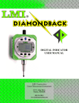
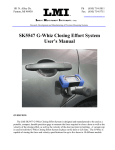
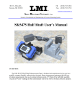
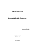
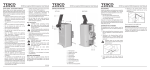
101 N. Alloy Dr. Fenton, MI 48430 Ph (810) 714-5811 Fax (810) 714-5711 [email protected] Research, Development and Manufacturing of Precision Measuring Systems “ACID LEVEL MEASUREMENT” 5 2 6 4 3 2 1 Required Equipment: 1 LMI 440 2 LMI SK5303 Sensor & Battery Compartment 3 LMI SK5304 master block 4 LMI 6009 4 pin – 4 pin cable 5 Battery Charger 6 Tool Belt USER MANUAL FOR THE LMI SK5303 SENSOR Form: CA 170 1/25/12 R:\Quality\Calibration Instructions\CA 170 SK5303 Acid Level Sensor.doc Rev: A Page 1 of 14 101 N. Alloy Dr. Fenton, MI 48430 Ph (810) 714-5811 Fax (810) 714-5711 [email protected] Research, Development and Manufacturing of Precision Measuring Systems OVERVIEW: The LMI SK5303 Sensor is designed and manufactured to be used as a portable, compact, durable precision electronic linear measurement instrument that delivers positive and negative deviation measurements from a set nominal reference point. The LMI SK5303 Sensor is compatible with many data collection systems on the market today and is used for accurately measuring the level of acid present in a battery. 1. LMI 440 Data collector: Set up routines, display measurements, and store data from the measurement sensor. Form: CA 170 1/25/12 R:\Quality\Calibration Instructions\CA 170 SK5303 Acid Level Sensor.doc Rev. A Page 2 of 14 101 N. Alloy Dr. Fenton, MI 48430 Ph (810) 714-5811 Fax (810) 714-5711 [email protected] Research, Development and Manufacturing of Precision Measuring Systems 2.1 Measurement Sensor: Custom acid-resistant handle, with ultrasonic distance measuring sensor. Connect 4-pin plug to port 4 on (Battery Compartment) by aligning pins and turning knurled portion of knob until snug. IMPORTANT NOTICE: The measurement sensor used in this device requires a Warm Up period for continuous accurate and stable results. Please see the table below. It takes 1-2 hours for minimal affect and 3-4 hours for a complete warm up. You can calibrate and use the unit right away, just be aware that during the warm-up period you will experience changes in accuracy until fully completed. You will simply have to re-master the unit frequently until it maintains stable readings. Due to this, we recommended the unit be left ON except when it is expected to set for extended periods of time to avoid frequent warm-ups. Also note the unit can be left ON while the battery is charging. 0 Change in Zero Position over time 0 100 200 300 400 500 600 700 800 -0.02 -0.04 -0.06 -0.08 -0.1 -0.12 Time (minutes) Form: CA 170 1/25/12 Series1 R:\Quality\Calibration Instructions\CA 170 SK5303 Acid Level Sensor.doc Rev: A Page 3 of 14 101 N. Alloy Dr. Fenton, MI 48430 Ph (810) 714-5811 Fax (810) 714-5711 [email protected] Research, Development and Manufacturing of Precision Measuring Systems 2.2 Battery Compartment: Communication unit with battery, charging port, sensor port, collector port, power switch, & status LED. 1. Power on/off rocker switch. 2. Status LED – RED/GREEN 4 2 3 3. Communication port - LMI 6009 cable to LMI 440 data collector. 4. Connector to attach measurement sensor. 5. Receptacle for battery charger plug. 1 5 3. LMI SK5304 Master Block: Stepped master for calibrating sensor prior to operation. 4. LMI 6009 4-pin to 4-pin cable: Connect this cable between the LMI 440 ports G4 or G5 and the battery compartment where it’s labeled “COLLECTOR”. Form: CA 170 1/25/12 R:\Quality\Calibration Instructions\CA 170 SK5303 Acid Level Sensor.doc Rev. A Page 4 of 14 101 N. Alloy Dr. Fenton, MI 48430 Ph (810) 714-5811 Fax (810) 714-5711 [email protected] Research, Development and Manufacturing of Precision Measuring Systems 5. Battery Charger: The measurement unit during operation will display a green LED. When the LED turns RED it’s time to charge the battery. Plug the charger into a standard wall outlet and connect the charging plug to the receptacle on the front of the battery compartment. There will be a short delay before the LED turns back to GREEN at the start of the charging cycle. The battery can be charged while the sensor is ON and during operation. a. Under continuous operation the battery will last approximately 95 hours when fully charged. b. The amount of time needed to fully re-charge the battery is approximately 4 hours. c. The light (LED) on the universal smart charger housing will change from RED to GREEN and automatically shut off when the battery is fully charged. Form: CA 170 1/25/12 R:\Quality\Calibration Instructions\CA 170 SK5303 Acid Level Sensor.doc Rev: A Page 5 of 14 101 N. Alloy Dr. Fenton, MI 48430 Ph (810) 714-5811 Fax (810) 714-5711 [email protected] Research, Development and Manufacturing of Precision Measuring Systems 6. Tool Belt: Designed to manage your equipment. It has many various sized compartments to arrange and store components. Form: CA 170 1/25/12 R:\Quality\Calibration Instructions\CA 170 SK5303 Acid Level Sensor.doc Rev. A Page 6 of 14 101 N. Alloy Dr. Fenton, MI 48430 Ph (810) 714-5811 Fax (810) 714-5711 [email protected] Research, Development and Manufacturing of Precision Measuring Systems LMI MODEL SK5303 SENSOR CALIBRATION AND MASTERING: Calibration is accomplished by inserting the sensor pilot into hole at the low and high step of the LMI SK5304 master block and steadying the shoulder on the top surface of the master. Mastering for the nominal position is done by inserting at the middle step of the LMI SK5304 labeled “MASTER “1.000”. Due to the large variety of data collection systems on the market, please contact LMI for specific calibration and mastering instructions. Configuration and Mastering Instruction for the LMI SK5303 Sensor to the LMI 440 This process will outline: Section I. II. Configuration of the LMI 440 Mastering the LMI SK5303 with SK5304 Pages 7-10 11-13 I. GAGE CONFIGURATION Section I is a one time setup. After a successful gage configuration is finished there should be no need to repeat section I. It is recommended to store a copy of the gage files onto a personal computer or laptop. Consult the collector manual or if purchased the TranSend manual for further details. 1. Press <menu> to turn on the collector. Form: CA 170 1/25/12 R:\Quality\Calibration Instructions\CA 170 SK5303 Acid Level Sensor.doc Rev: A Page 7 of 14 101 N. Alloy Dr. Fenton, MI 48430 Ph (810) 714-5811 Fax (810) 714-5711 [email protected] Research, Development and Manufacturing of Precision Measuring Systems 2. Press to highlight “Gage”. 3. Press <enter>. It is recommended to assign simple user name to the gage files such as; SK5303, sensor, etc. This will help to identify different setups. 4. To assign a gage file name press the ▲ or ▼ to highlight gage “G4”* in the “Gage List”, and press <enter> on the collector. The alphanumeric screen will then appear. *G4 and G5 can both read the SK5303 Sensor. The only rule to follow is the gage file must match the source code in part file, see collector manual for details. The balance of this instruction will be based on G4. To use G5, perform the following steps using the G5 gage file. Form: CA 170 2/02/12 R:\Quality\Calibration Instructions\CA 170 SK5303 Acid Level Sensor.doc Rev: A Page 8 of 14 115 S. Ann Street PO Box 507 Byron, MI 48418 Ph (810) 266-5811 Fax (810) 266-5711 [email protected] Research, Development and Manufacturing of Precision Measuring Systems 5. Use the ▲, ►, ◄, or ▼ to highlight the desired character then press <enter>, repeat process until the gage file name is spelled out then press ►► to accept the new name. 6. Press the ► to “Configure”. By default the screen should read as follows. This screen determines how the collector will interpret the signal from the gage. Failure to set this screen properly may cause undesired results. If no changes to the screen are required, configuration is complete and press the <menu> key. See Note below for Johnson Controls specific Configuration information. Note: Form: CA 170 1/25/12 R:\Quality\Calibration Instructions\CA 170 SK5303 Acid Level Sensor.doc Rev: A Page 9 of 14 101 N. Alloy Dr. Fenton, MI 48430 Ph (810) 714-5811 Fax (810) 714-5711 [email protected] Research, Development and Manufacturing of Precision Measuring Systems To master using the LMI SK5304 Master Block you must set the “Scale:” on the Configuration screen to 3.25” (this is the overall range of the unit as mastered). Another important detail to understand in the Configuration setup pertains to the “Zero Master:”. Using as an Example: Group 27 acid level nominal of 1.21”. - Set “Zero Master” to .21” and carry out the calibration steps in the Section II mastering instruction. - When mastering the gage at the “master” step 1.000” your sensor will display “0.00” on a perfect 1.21” acid level battery. Any variation in acid level will read a positive (acid above nominal) or – negative (acid below nominal) figure. + - Group 31 acid level nominal of 1.52” set “Zero Master” to .52”. Apply this theory to any other acid level nominal requirement. 7. If changes in this screen are needed, press the ▲ or ▼ to highlight the different selections then press <enter> to toggle through the choices of “Type”, “Master Type”, and “Zero Before Read”. 8. To make changes to the “Scale” or “Zero Master” press ▲ or ▼ to highlight “Scale” or “Zero Master” and press <enter>. This will bring up the numeric keypad. Key in the new value and press ►► to accept. 9. Press the <menu> key to return to the “Main Menu”. If any changes were made in the “Gage Configuration” screen a save gage notification will appear. If the changes are intentional highlight “Save to current gage” and press <enter>. If changes are not intended, highlight “Cancel” and press <enter> and reset “Configure Gages” per step 6. Gage configuration is complete II. MASTERING INSTRUCTIONS LMI suggests that this process be performed at the start of every shift. Form: CA 170 2/02/12 R:\Quality\Calibration Instructions\CA 170 SK5303 Acid Level Sensor.doc Rev: A Page 10 of 14 115 S. Ann Street PO Box 507 Byron, MI 48418 Ph (810) 266-5811 Fax (810) 266-5711 [email protected] Research, Development and Manufacturing of Precision Measuring Systems 1. Connect the sensor to Gage Port 4 of the data collector. If G5 was selected in gage configuration use Gage Port 5. 2. Press <Menu> to turn on the LMI 440. 3. Press ▼ to highlight “Gage”. 4. Press <enter>. 5 From the gage list use the ▲ or ▼ keys on the data collector to choose gage file G4, and press ◄ on the collector. Form: CA 170 1/25/12 R:\Quality\Calibration Instructions\CA 170 SK5303 Acid Level Sensor.doc Rev: A Page 11 of 14 101 N. Alloy Dr. Fenton, MI 48430 Ph (810) 714-5811 Fax (810) 714-5711 [email protected] Research, Development and Manufacturing of Precision Measuring Systems 6 “Master” will be highlighted in screen header and “G4” is identified as “Gage Port”. If G4 is not the Gage Port press the ►► or ◄◄ until G4 appears. “G4” is the Gage Port “Master” highlighted 7 Place the sensor into the top or “Lo” step of LMI SK5304 Master Block. Verify “Master Lo” is highlighted on the collector, press <enter>. 8 Place the sensor into the bottom or “Hi” step of the LMI SK5304 Master Block. Verify “Master Hi” is highlighted on the collector, press <enter>. Form: CA 170 2/02/12 R:\Quality\Calibration Instructions\CA 170 SK5303 Acid Level Sensor.doc Rev: A Page 12 of 14 115 S. Ann Street PO Box 507 Byron, MI 48418 Ph (810) 266-5811 Fax (810) 266-5711 [email protected] Research, Development and Manufacturing of Precision Measuring Systems 9 Position the sensor into the calibration block’s center or Master. Verify “Master Zero” is highlighted on the collector, press <enter>. Calibration/ Mastering for the LMI SK5303 Sensor is now complete. MAKING THE CHECK: Form: CA 170 1/25/12 R:\Quality\Calibration Instructions\CA 170 SK5303 Acid Level Sensor.doc Rev: A Page 13 of 14 101 N. Alloy Dr. Fenton, MI 48430 Ph (810) 714-5811 Fax (810) 714-5711 [email protected] Research, Development and Manufacturing of Precision Measuring Systems Using the pre-calibrated and mastered LMI SK5303 Sensor, insert the sensor pilot into any battery fill hole set up in that group. Verify the shoulder on the end affecter is firmly seated against the face of the battery lid. The LMI SK5303 sensor is now ready for the reading to be sampled. Press the enter key to sample a reading. Once the sensor reading has been recorded, remove it from the fill hole and continue to the next until each depth has been measured. Form: CA 170 2/02/12 R:\Quality\Calibration Instructions\CA 170 SK5303 Acid Level Sensor.doc Rev: A Page 14 of 14