1
AXIS A1001 Network Door Controller & AXIS Entry Manager
Technical Specifications
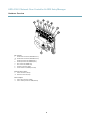
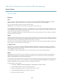
Reader Data Connector
6-pin terminal block supporting RS485 and Wiegand protocols for communication with the
reader.
The RS485 ports support:
• Two-wire RS485 half duplex
• Four-wire RS485 full duplex
The Wiegand ports support:
• Two-wire Wiegand
Function
RS485
RS485
Wiegand
Pin
Notes
B-
1
A+
2
For full duplex RS485
For half duplex RS485
B-
3
A+
4
Data 0
5
Data 1
6
For full duplex RS485
For half duplex RS485
For Wiegand
Important
The recommended maximum cable length is 30 m (98.4 ft).
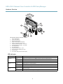
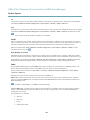
Reader I/O Connector
6-pin terminal block for:
•
•
•
•
Auxiliary power (DC output)
Digital Input
Digital Output
0 V DC (-)
Function
Pin
Notes
0 V DC (-)
1
DC output
2
For powering auxiliary equipment.
Note: This pin can only be used as power out.
12 V DC
Max load = 300 mA
Configurable (Input
or Output)
3–6
Digital input — Connect to pin 1 to activate, or leave
floating (unconnected) to deactivate.
0 to max 40 V DC
Digital output — Connected to pin 1 when activated,
floating (unconnected) when deactivated. If used
with an inductive load, e.g. a relay, a diode must be
connected in parallel with the load, for protection
against voltage transients.
0 to max 40 V DC, open drain,
100 mA
Specifications
0 V DC
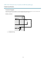
Door Connector
Two 4-pin terminal blocks for door monitoring devices (digital input).
48