1
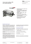
Absolut encoder with EtherCAT® interface Document no.:CRK 11780 EE Accompanying data sheet TRK 12825 or CRK 11778 Date: 10.09.2013 user manual TWK-ELEKTRONIK GmbH Heinrichstrasse 85 D-40041 Düsseldorf Postbox 10 50 63 Tel. +49 211 96117-0 Fax +49 211 637705 [email protected] www.twk.de COPYRIGHT: The Operating Instructions CRK 11780 is owned by TWK-ELEKTRONIK GMBH and is protected by copyright laws and international treaty provisions. © 2013 by TWK-ELEKTRONIK GMBH POB 10 50 63 ■ 40041 Düsseldorf ■ Germany Tel. +49/211/63 20 67 ■ Fax +49/211/63 77 05 [email protected] ■ www.twk.de EtherCAT® ist eine eingetragene Marke und patentierte Technologie, lizenziert durch die Beckhoff Automation GmbH, Deutschland. Date: 10.09.2013 Page 2 of 18 document no. CRK 11780 EE Table of contents Table of contents 1. Safety instructions.............................................................................................................. 5 2. General................................................................................................................................. 6 3. Installation instructions...................................................................................................... 6 3.1 Connection via M12 connector.....................................................................................................6 3.2 EtherCAT wiring............................................................................................................................6 3.3 Addressing....................................................................................................................................7 3.4 Status LEDs..................................................................................................................................7 3.5 XML file.........................................................................................................................................7 4. Process data exchange...................................................................................................... 8 4.1 Position data format (position_value)...........................................................................................8 4.2 Control word data format (control_value).....................................................................................8 5. Programming and diagnosis (CANopen over EtherCAT)................................................ 9 5.1 Overview of the object directory...................................................................................................9 5.2 Communication parameters........................................................................................................10 5.2.1 Object 1000h - Device type...................................................................................................10 5.2.2 Object 1008h - Manufacturer device name............................................................................10 5.2.3 Object 1009h - Manufacturer hardware version....................................................................10 5.2.4 Object 100Ah - Manufacturer software version.....................................................................10 5.2.5 Object 1010h - Store parameters..........................................................................................10 5.2.6 Object 1011h - Restore default parameters...........................................................................10 5.2.7 Object 1018h - Identity Object............................................................................................... 11 5.2.8 Object 1600h - Receive PDO mapping.................................................................................. 11 5.2.9 Object 1A00h - Transmit PDO mapping................................................................................ 11 5.2.10 Object 1C12h - Sync manager channel 2 (process data output)......................................... 11 5.2.11 Object 1C13h - Sync manager channel 3 (process data input)........................................... 11 5.3 Manufacturer-specific parameters..............................................................................................12 5.3.1 Object 2000h - State value....................................................................................................12 5.3.2 Object 2001h - Control value.................................................................................................12 5.4 Standardised device parameters................................................................................................13 5.4.1 Object 6000h - Operating parameters...................................................................................13 5.4.2 Object 6001h - Measuring units per revolution......................................................................13 5.4.3 Object 6002h - Total measuring range in measuring units....................................................13 5.4.4 Object 6003h - Preset............................................................................................................14 5.4.5 Object 6004h - Position..........................................................................................................14 5.5 Standardised device diagnosis ..................................................................................................15 5.5.1 Object 6500h - Operating status............................................................................................15 5.5.2 Object 6501h - Singleturn resolution.....................................................................................15 Date: 10.09.2013 Page 3 of 18 document no. CRK 11780 EE Table of contents 5.5.3 Object 6502h - Number of distinguishable revolutions..........................................................15 5.5.4 Object 6503h - Alarms...........................................................................................................15 5.5.5 Object 6504h - Supported alarms..........................................................................................15 5.5.6 Object 6509h - Offset.............................................................................................................15 6. TwinCAT system manager................................................................................................ 16 6.1 Installation der XML-Datei..........................................................................................................16 6.2 Online commissioning.................................................................................................................16 Date: 10.09.2013 Page 4 of 18 document no. CRK 11780 EE 1. Safety instructions 1. Safety instructions 1.1 Scope of validity This user manual applies exclusively to the following rotary encoders with PROFIsafe interface: - CRKxx-xxxxR4096C1M01 - TRKxx-xxxxxxR4096C1MK01 1.2 Documentation The following documents must be noted: - The owner's system-specific operating instructions - This user manual - Data sheet number CRK11778 or TRK12825 - The pin assignment enclosed with the device - Installation instruction TZY 10206 enclosed with the device 1.3 Proper use TWK-ELEKTRONIK GmbH's rotary encoders and linear transducers are used to record rotary and linear positions, and make their measured values available as an electric output signal. As part of a system, they must be connected to the downstream electronics and must only be used for this purpose. 1.4 Commissioning • The relevant device must only be set up and operated using this document and the documentation specified in point 1.2. • Protect the device against mechanical damage during installation and operation. • The device must only be commissioned and set up by a specialist electrician. • Do not operate the device outside of the limit values which are specified in the data sheet. • Check all electrical connections before commissioning the system. Date: 10.09.2013 Page 5 of 18 document no. CRK 11780 EE 2. General 3. Installation instructions 2. General The CRK electro-optical absolute encoders are designed for direct connection to the EtherCAT industrial Ethernet system. Use of the CANopen over EtherCAT message (CoE) enables parameters and diagnostic data to be handled as usual in the case of CANopen. The EtherCAT specifications can be obtained from the EtherCAT Technology Group ETG (www.ethercat.org). 3. Installation instructions 3.1 Connection via M12 connector The „...M01“ type absolute encoders have separate connectors for the supply and the EtherCAT system. Device connectors: - M12x4 D-coded socket: - M12x4 D-coded socket: - M12x4 A-coded pins: Bus in Bus out 24 V voltage supply UB L/A1 L/A2 NS View of the rear of the encoder (see data sheet CRK11778 for connector assignment) IN OUT 3.2 EtherCAT wiring The physical characteristics of the interface are based on the 100BASE-TX Ethernet standard in accordance with ISO/ I EC 8802-3. As a result of this: - The EtherCAT cable must at least meet the requirements according to CAT5. - The max. cable length between two subscribers may be 100 m. - Setting the baud rate is not possible/necessary. In the case of EtherCAT, the network topology normally has a linear structure. However, tree structures or branch-off lines may also be implemented by means of bus modules with an integrated switch port. In contrast to the EDP networks which are usual today, hubs are not permissible, and a standard switch is only permitted directly to the rear of the master (the first subscriber must then possess a MAC address). For wiring purposes, we recommend pre-assembled data cables with M12 connectors moulded on at both ends. These can be ordered from us in various lengths (see data sheet CRK11778). Terminating resistors are not necessary. Date: 10.09.2013 Page 6 of 18 document no. CRK 11780 EE 3. Installation instructions 3.3 Addressing Manually setting the subscriber address is not necessary. It is assigned automatically by the EtherCAT master in accordance with the physical sequence in the bus. 3.4 Status LEDs Four LEDs are housed in the absolute encoder‘s connecting cap. These have the following meanings: UB (VB) green Link/ Activity1 (L/A1) green Link/ Activity2 (L/A2) green Status (NS) Description green/red on Operating voltage available on Network connection established flashing Netzwerk activ on Network connection established flashing Netzwerk activ off green/ flashing 1 time green/ normal flashing green on red flashing red on Initialisation Safe-operational Pre-operational Operational Impermissible parameter or pre-set value No response from the master Brief flickering on the part of the red status (NS) LED after switching on the voltage indicates the absolute encoder‘s booting process. 3.5 XML file An XML file to integrate the absolute encoder into a project planning tool is available for download on our website www.twk.de (under documentation). This describes the features of the EtherCAT subscriber in the standardised XML format. After integrating the XML file into the project planning tool (e.g. TwinCAT System Manager from Beckhoff), the absolute encoder can be integrated off-line into the bus. However, access to the parameters and diagnostic information (CANopen over EtherCAT) is only possible after reading these out (online) from the absolute encoder. See Chapter 6. Date: 10.09.2013 Page 7 of 18 document no. CRK 11780 EE 4. Process data exchange 4. Process data exchange The absolute encoder transmits its position (4 bytes) and receives a control word (2 bytes) as process data objects (PDO). The data format is as follows: 4.1 Position data format (position_value) Byte 0 Byte 1 Byte 2 Byte 3 7 6 5 4 3 2 1 0 15 14 13 12 11 10 9 8 23 22 21 20 19 18 17 16 31 30 29 28 27 26 25 24 32 bit position_value The positions are depicted in Intel format (Little Endian). The absolute encoder‘s counting direction, resolution and total number of steps can be changed via the CoE parameters 6000h, 6001h and 6002h. Failsafe storage of the modified parameters is carried out via the CoE parameter 1010h. See Chapter 5.2.5 and Chapter 5.4. 4.2 Control word data format (control_value) Byte 0 Byte 1 7 6 5 4 3 2 1 0 15 14 13 12 11 10 9 8 16 bit control_value Bit 0 Meaning Comment Set pre-set A flank change from 0 to 1 sets the previously programmed pre-set value (CoE parameter 6003h). Default value: 0 Scaling must be switched on to set the pre-set value (CoE parameter 6000h). Also see Chapter 5.4. Additionally saving the pre-set (offset) value via object 1010h is not necessary. 1 - 15 Not used Date: 10.09.2013 Page 8 of 18 document no. CRK 11780 EE 5. Programming and diagnosis 5. Programming and diagnosis (CANopen over EtherCAT) In the case of CANopen over EtherCAT, all parameters and diagnostic information are located in what is called the object directory. By specifying their index and sub-index, they can be modified or read there with the SDO (Service Data Object) message. The object directory is sub-divided into the following areas: Communication parameters Manufacturer-specific parameters Standardised device parameters Index 1000h - 1FFFh Index 2000h - 5FFFh Index 6000h - 9FFFh Refer to the following tables for a description of the individual parameters and diagnostic information. 5.1 Overview of the object directory Index Object Communication Profile Area VAR 1000h VAR 1008h VAR 1009h VAR 100Ah 1010h RECORD 1011h RECORD RECORD 1018h RECORD 1600h RECORD 1A00h RECORD 1C12h 1C13h RECORD Name device_type manufacturer_device_name manufacturer_hardware_version manufacturer_software_version store_parameters restore_default_parameters identity_object receive_PDO_mapping transmit_PDO_mapping sync_manager_RxPDO_assign sync_manager_TxPDO_assign Manufacturer Specific Profile Area 2000h VAR state_value 2001h VAR control_value Standardised Device Profile Area VAR operating_parameters 6000h VAR measuring_units_per_revolution 6001h VAR total_measuring_range_in_measuring_units 6002h VAR preset_value 6003h VAR position_value 6004h VAR operating_status 6500h VAR singleturn_resolution 6501h VAR number_of_distinguishable_revolutions 6502h VAR alarms 6503h VAR supported_alarms 6504h VAR offset_value 6509h Date: 10.09.2013 Page 9 of 18 Data type Access Unsigned32 String String String ro ro ro ro rw rw ro ro ro ro ro Unsigned16 Unsigned16 ro ro Unsigned16 Unsigned32 Unsigned32 Unsigned32 Unsigned32 Unsigned16 Unsigned32 Unsigned32 Unsigned16 Unsigned16 Unsigned32 rw rw rw rw ro ro ro ro ro ro ro document no. CRK 11780 EE 5. Programming and diagnosis 5.2 Communication parameters 5.2.1 Object 1000h - Device type Index Sub 1000h 00 Name device_type Data type Access Range/Value Unsigned32 ro 0x20196 Default 5.2.2 Object 1008h - Manufacturer device name Index Sub 1008h 00 Name manufacturer_device_name Data type Access String ro Range/Value Default e.g. CRKxx12R12C1xx 5.2.3 Object 1009h - Manufacturer hardware version Index Sub 1009h 00 Name Data type Access String ro manufacturer_hardware_version Range/Value Default Contains the current manufacturer hardware version e.g.: “2.00” 5.2.4 Object 100Ah - Manufacturer software version Index Sub 100Ah 00 Name Data type Access String ro manufacturer_software_version Range/Value Default Contains the current manufacturer software version e.g.: “3.00” 5.2.5 Object 1010h - Store parameters Index Sub Name Data type Access Range/Value 1010h 00 largest_supported_subindex Unsigned8 ro 1 01 save_all_parameters Unsigned32 ro 1 Default Writing “save” (hex: 0x65766173) in sub-index 1 leads to the failsafe saving of the parameters in the EEPROM. Following execution, the value is reset to “1”. 5.2.6 Object 1011h - Restore default parameters Index Sub Name Data type Access Range/Value 1600h 00 largest_supported_subindex Unsigned8 ro 1 01 load_default_parameters Unsigned32 ro 1 Default By writing “load” (hex: 0x64616F6C) in sub-index 1, the parameters’ default values are loaded into the EEPROM and become immediately active. Following execution, the value is reset to “1”. Date: 10.09.2013 Page 10 of 18 document no. CRK 11780 EE 5. Programming and diagnosis 5.2.7 Object 1018h - Identity Object Index Sub Name Data type Access Range/Value 1018h 00 largest_supported_subindex Unsigned8 ro 4 01 vendor_id Unsigned32 ro 0x10D 02 product_code Unsigned32 ro 0x1000 03 revision_number Unsigned32 ro 0x00010001 04 serial_number Unsigned32 ro XXXX XXXX Default 5.2.8 Object 1600h - Receive PDO mapping Index Sub Name Data type Access Range/Value 1600h 00 largest_supported_subindex Unsigned8 ro 1 01 receive_mapping_object Unsigned32 ro 0x20010010 Default The encoder receives the control byte index 0x2001 as PDO. 5.2.9 Object 1A00h - Transmit PDO mapping Index Sub Name Data type Access Range/Value 1A00h 00 largest_supported_subindex Unsigned8 ro 1 01 transmit_mapping_object Unsigned32 ro 0x60040020 Default The encoder transmits the position value index 0x6004 as PDO. 5.2.10 Object 1C12h - Sync manager channel 2 (process data output) Index Sub Name Data type Access Range/Value 1C12h 00 number_of_RxPDOs Unsigned8 ro 1 01 receive_assign_object Unsigned16 ro 0x1600 Default 5.2.11 Object 1C13h - Sync manager channel 3 (process data input) Index Sub Name Data type Access Range/Value 1C13h 00 number_of_TxPDOs Unsigned8 ro 1 01 transmit_assign_object Unsigned16 ro 0x1A00 Date: 10.09.2013 Page 11 of 18 Default document no. CRK 11780 EE 5. Programming and diagnosis 5.3 Manufacturer-specific parameters 5.3.1 Object 2000h - State value Index Sub 2000h 00 Name state_value Data type Access Range/Value Default Unsigned16 ro 0...15 0 The object 2000h displays detailed parameterisation errors and information. An entry in state_value is displayed by the highest-value bit in the object 6503h “Alarms” (Chapter 5.5.4). The red status LED also flashes in addition to the current green status. (Also see Chapter 3.4) The bits have the following meanings: Bit Meaning Remedy 0 Impermissible bits set in the parameter „operating_parameters“ (object 6000h) Re-write the parameter with permissible values 1 Impermissible value in the parameter „measuring_units_per_revolution“ (Object 6001h) Re-write the parameter with permissible values 2 Impermissible value in the parameter „total_ measuring_range_in_measuring_units“ (object 6002h) Re-write the parameter with permissible values 3 Due to a current error, the „save_all_parameters“ function has not been carried out First rectify the error which was present prior to „save_all_parameters“. Then execute the command again. 4 Impermissible value in the parameter „preset“ (object 6003h) Re-write the parameter with permissible values 5 Error in the flash; the parameters have been set to default values 6 Internal error 7 - 14 15 Switch power supply off/on Not used Collective error 5.3.2 Object 2001h - Control value Index Sub 2001h 00 Name control_value Data type Access Range/Value Default Unsigned16 ro 0,1 0 The bits have the following meanings: Bit 0 1 - 15 Meaning A flank change from 0 to 1 sets the previously programmed pre-set value (CoE parameter 6003h). Default value: 0 The scaling must be switched on to set the pre-set value (CoE parameter 6000h). Also see Chapter 5.4. Additionally saving the pre-set (offset) value via the object 1010h is not necessary. Not used Access to the control word is only possible via a PDO. In the object directory, it is “read only”! Date: 10.09.2013 Page 12 of 18 document no. CRK 11780 EE 5. Programming and diagnosis 5.4 Standardised device parameters Those parameters marked with “rw” in this chapter can be set by the user. To store the parameters in a failsafe manner in the encoder’s EEPROM, the “save” command must then be executed under the object 1010h. See Chapter 5.2.5 5.4.1 Object 6000h - Operating parameters Index Sub 6000h 00 Bit 0 Name operating_value Name 0 Code sense Data type Access Range/Value Default Unsigned32 rw 0,1,4,5 0 1 CW Ascending position value on clockwise rotation of the shaft, viewed in the direction of the shaft CCW Ascending position value on counter-clockwise rotation of the shaft, viewed in the direction of the shaft 1 Not used 2 Scaling off The absolute encoder operates with the default values of the resolution, total number of steps and pre-set (offset) parameters. Editing of the parameters is blocked. on 3 - 31 The absolute encoder operates with the values last stored for the parameters. Editing of the parameters is enabled. Not used 5.4.2 Object 6001h - Measuring units per revolution Index Sub 6001h 00 Name measuring_units_per_revolution Data type Access Range/Value Default Unsigned32 rw 1...4096 (8192*) 4096 This parameter can be used to set the absolute encoder’s resolution in steps per revolution. Before changing the resolution, scaling must be switched on via object 6000h bit 2. 5.4.3 Object 6002h - Total measuring range in measuring units Index Sub 6002h 00 Name total_measuring_range_in_ measuring_units Data type Access Range/Value Default Unsigned32 rw 1...16777216 (33554432*) 16777216 This parameter can be used to set the absolute encoder’s total number of steps. The total number of steps is the product of the resolution and the number of revolutions. Before changing the resolution, scaling must be switched on via object 6000h bit 2. Note: It must be noted that internal calculation of the number of revolutions within the encoder is carried out in powers of 2. Irrespective of this requirement, the user can programme the desired total number of steps and the desired resolution according to the application. If necessary, the absolute encoder makes use of the next highest power of 2 during calculation. In this case, the values are designated as the actual resolution or the actual total number of steps and are displayed as the parameter value. Example: Desired total number of steps: Desired resolution: 20,480 4096 *The values in brackets are valid for encoders with 13 Bit resolution Date: 10.09.2013 Page 13 of 18 document no. CRK 11780 EE 5. Programming and diagnosis Desired number of revolutions: 5 Next highest 2n revolution number: 8 The following results from this: Actual total number of steps: Actual resolution: 32,768 4096 5.4.4 Object 6003h - Preset Index Sub 6003h 00 Name preset_value Data type Access Range/Value Unsigned32 rw 0 ... total No. of steps - 1 Default This parameter can be used to set the absolute encoder’s position value to any arbitrary value within its total number of steps. The value entered here is output directly as the new position value. The difference between the displayed and the internal position value is stored as the offset in object 6509h. Before changing the pre-set value, scaling must be switched on via object 6000h bit 2. The pre-set value can also be set via the PDO “control_value” in the I/O data traffic. See Chapter 5.3.2 5.4.5 Object 6004h - Position Index Sub 6004h 00 Name position_value Data type Access Range/Value Unsigned32 ro 0 ... total No. of steps - 1 Default This value is the position value and is output via the PDOs. (See Chapter 4) Date: 10.09.2013 Page 14 of 18 document no. CRK 11780 EE 5. Programming and diagnosis 5.5 Standardised device diagnosis 5.5.1 Object 6500h - Operating status Index Sub 6500h 00 Name operating_status Data type Access Range/Value Default Unsigned16 ro 0,1,4 0 The object 6500h depicts the operating status of the absolute encoder. The bits have the same meaning as in the object 6000h. 5.5.2 Object 6501h - Singleturn resolution Index Sub 6501h 00 Name singleturn_resolution Data type Access Range/Value Unsigned32 ro 4096 (8192*) Default Specifies the maximum resolution which can be set. 5.5.3 Object 6502h - Number of distinguishable revolutions Index Sub 6502h 00 Name number_of_distinguishable_revolutions Data type Access Range/Value Unsigned16 ro 4096 Range/Value Default Specifies the maximum number of revolutions. 5.5.4 Object 6503h - Alarms Index Sub Name Data type Access 6503h 00 alarms Unsigned16 ro Bit Meaning 0 - 14 Not used 15 Default 0 Collective error (for further information, see object 2000h state_value (Chapter 5.3.1)) 5.5.5 Object 6504h - Supported alarms Index Sub 6504h 00 Name supported_alarms Bit Meaning 0 - 14 Not used 15 Data type Access Range/Value Unsigned16 ro 8000 Data type Access Range/Value Unsigned32 ro Default Collective error 5.5.6 Object 6509h - Offset Index Sub 6509h 00 Name offset_value Default 0 See object 6003h pre-set (Chapter 5.4.4) *The values in brackets are valid for encoders with 13 Bit resolution Date: 10.09.2013 Page 15 of 18 document no. CRK 11780 EE 6. TwinCAT System Manager 6. TwinCAT system manager 6.1 Installation der XML-Datei - Copy the downloaded XML file to the ..\Twincat\Io\Ethercat directory - Start the TwinCAT system manager 6.2 Online commissioning If the system is connected and capable of running, reading-in the bus structure online is the simplest option. This procedure is described here examplarily for the encoder CRK. Create a new project, mark “I/O devices” and click onto the “wand”. Confirm the following note with OK. TwinCAT should then locate your network card. Confirm this with OK. Date: 10.09.2013 Page 16 of 18 document no. CRK 11780 EE 6. TwinCAT System Manager After confirming the following dialogue with “Yes”, all connected devices should be located. In this case, the EtherCAT master (device 1), a Beckhoff bus terminal with I/O modules and the TWK CRK absolute encoder. If the so-called free run is now also activated, the I/O data are cyclically exchanged and can be monitored in the TwinCAT. Clicking onto the CRK’s “Inputs” displays the absolute encoder’s input data. Date: 10.09.2013 Page 17 of 18 document no. CRK 11780 EE 6. TwinCAT System Manager If you click onto the CRK itself instead, the following screen’s register takes you to the absolute encoder’s configuration and parameterisation. The CoE online register accesses the parameter and diagnostic data. All parameters identified with “RW” can be changed. The description of the parameters can be found in Chapter 4. After changing the parameters, do not forget to save them in a failsafe manner via parameter 1010h. Date: 10.09.2013 Page 18 of 18 document no. CRK 11780 EE