1
Copyright
MODEL
OM-9300
(POS THERMAL PRINTER)
OM-9300 Portable printer user’s manual.
Copyright ⓒ2004 by OMNIPrint Inc.
All rights reserved.
The information contained in this manual is the property of OMNIPrint Inc. and
may not be reproduced in whole or in part without the prior written permission
of OMNIPrint Inc.
Trademark
is a registered trademark of OMNIPrint Inc.
All other trademarks are the properties of their respective companies.
Caution
Some semiconductor devices are easily damaged by static electricity. You
should turn the printer “OFF”, before you connect or removed the cable on the
rear side, in order to guard the printer against the static electricity.
If the printer is damaged by the static electricity, you should turn the printer
“OFF”.
OMNIPrint Inc.
Notice
14 Chrysler
Irvine, CA 92618
United States
Tel : 1-949-457-0229
Fax : 1-949-457-9016
The contents of this manual are subject to change without notice.
http://www.omniprintinc.com
Rev 1.0a
2
www.omniprintinc.com
FCC CLASS A
Operating Precaution
FCC COMPLIANCE STATEMENT FOR AMERICAN USERS
This equipment has been tested and found to comply with the limits for a Class
A digital device, pursuant to Part 15 of the FCC Rules. These limits are
designed to provide reasonable protection against harmful interference when
the equipment is operated in a commercial environment. This equipment
generates, uses and can radiate radio frequency energy and if not installed
and used in accordance with the instruction manual, may cause harmful
interference to radio communications. Operation of this equipment in a
residential area is likely to cause harmful interference, in which cause the user
will be required to correct the interference at his/her own expense.
X When using the Printer
● Be careful not to drop or bump the printer on a hard surface.
● Do not install the printer in direct sunlight or such areas. Suitable
environment for the use of the printer is as follows:
◆ Operating temperature : 5°C to 45°C
◆ Relative humidity : 10% to 90% (No condensation)
● Do not install the printer near devices that generate strong
electromagnetic fields such as a copy machine.
● Do not open the platen cover during printing .
● Do not remove or reinstall the communication cable during printing or
transmission.
● Do not touch the connectors of the communication cable during printing.
● Switch the POWER OFF when not in use.
● Do not use alcohol or other solvent when cleaning.
● The AC adapter may become warm when in use. This is normal and is
not a malfunction.
FOR CANADIAN USERS
This digital apparatus does not exceed the Class A limits for radio noise
emissions from digital apparatus as set out in the radio interference regulations
of the Canadian Department of Communications.
Le present appareil numerique n’emet pas de bruits radioelectriques
depassant les limits applicables aux appareils numeriques de Class A
preccrites dans le reglement sur le brouillage radiolectrique edicte par le
Ministere des Communications du Canada.
www.omniprintinc.com
X Thermal Paper Handling
●
●
●
●
Store the thermal paper in a cool, dry and dark place.
Do not rub the paper with hard object.
Do not leave the paper with hard object.
Do not allow plastic film, erasers, or adhesive tape to touch the paper for
long periods.
● Do not stack the thermal paper with diazo copies immediately after
copying or wet-type copies.
● Do not use chemical glue.
● Always use the clean thermal paper.
3
4
www.omniprintinc.com
Chapter 1. PARTS IDENTIFICATIONS
CONTENTS
● CHAPTER 1.
PARTS IDENTIFICATIONS
6
● CHAPTER 2. PREPARATION
2.1. Unpacking
2.2. Connecting the cable
2.3. Loading the roll paper setting
2.4. DIP switch settings
7
7
8
11
13
● CHAPTER 3. CONTROL PANEL
3.1. Control panel
3.2. Error indicator
17
17
17
● CHAPTER 4.
SELF-TEST
18
● CHAPTER 5.
HEXADECIMAL DUMP
19
● CHAPTER 6. SPECIFICATIONS
6.1. General specifications
6.2. Auto cutter specification
6.3. Interface
6.4. Electrical Characteristics
6.5. Environmental requirements
6.6. Reliability
6.7. Black mark specifications
20
20
21
21
21
22
22
23
● CHAPTER 7.
24
COMMAND SET LIST
● APPENDIX
A.1. Ordering information
A.2. Printer mechanism handling
A.3. Thermal paper handling
www.omniprintinc.com
26
26
26
26
5
6
www.omniprintinc.com
Chapter 2. PREPARATION
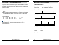
2.2. Connecting the cable
2.1. Unpacking
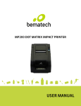
You can connect up to four cables to the printer. They all connect to the
connector panel on the back of the printer as shown below:
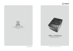
When unpacking your printer box, make sure it contains the printer and all
accessories. If any accessories is missing or damage, please contact your
dealer for assistance.
OM-9300 printer
AC adapter
User’s Manual
Roll Paper
Interface cable
Before connecting any of the cables, make sure that both the printer and the
computer are turned off.
www.omniprintinc.com
7
8
www.omniprintinc.com
2.2.1. Serial interface (D-SUB 25 pin female connector)
PIN
SIGNAL
2
TxD
I/O
DESCRIPTION
-
Printer transmit data line RS-232C level
3
RxD
-
Printer receive data line RS-232C level
4, 20
DTR
Output
Printer handshake to host line RS-232C level
6
DSR
Input
Data Send Ready
1, 7
GND
-
System Ground
2.2.2. USB interface (4-pin “B” Type USB connector)
PIN
SIGNAL
I/O
DESCRIPTION
1
+5V
-
+5V
2
DATA-
-
Printer transmit data line
3
DATA+
-
Printer transmit data line
4
GND
-
System Ground
SIGNAL
I/O
DESCRIPTION
1
2-9
10
11
12
13
14
15
16
17
18
19-30
31
32
33
34
35
36
STROBEDATA0-7
ACKBUSY
PE
SELECT
AUTO FEEDGROUND
GROUND
NC
LOGIC-H
GROUND
INITERRORGROUND
NC
+5V
SELLECT IN-
Input
Input
Output
Output
Output
Output
Input
Input
Output
Input
Synchronize signal Data received
Data bit Transmitted 0 – 7
Data receiving competed
Impossible to printer data receiving
Paper empty
Printer’s status for ON/OFF line
ND
System Ground
System Ground
+5V
System Ground
Initialize
Printer Error
System Ground
+5V
ND
2.2.4. Cash Drawer Connector
The printer can operate two cash drawers with a 6 pin RJ-11 modular
connector. The driver is capable of supplying a maximum current of 1.0 A for
510 ms or less when not printing.
PIN
2.2.3. Parallel interface (Centronics parallel connector)
www.omniprintinc.com
PIN
9
10
SIGNAL
1
Signal GND
2
Drawer kick-out drive signal 1
3
Drawer open/close signal
4
+24V
5
Drawer kick-out drive signal 2
6
Signal GND
www.omniprintinc.com
DESCRIPTION
Output
Input
Output
-
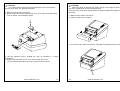
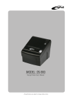
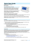
2.3. Loading the Roll Paper
5. Be sure to note the correct direction that the paper comes off the roll.
Notes: Be sure to use paper rolls that meet the specifications. Do not
use paper rolls that have the paper glued to the core because the
printer cannot detect the paper end correctly. (Turn Off Power switch)
☞ Turn Off Power switch
1. Make sure that the printer is not receiving data; otherwise, data may be lost.
2. Open the paper roll cover by pulling down the cover-open lever.
6. Pull out a small amount of paper, as shown. Then, close the cover.
3. Remove the used paper roll core if there is one.
4. Insert new paper roll as shown below.
7. Tear off the paper as shown.
www.omniprintinc.com
11
12
www.omniprintinc.com
2.4. DIP Switch Setting
2.4.2. Parallel Interface Specification
The OM-9300 is set up at the factory to be appropriate for almost all
users. It does, however, offer some settings for users with special
requirements. It has DIP switches that allow you to change communication
setting, such as handshaking and parity check, as well as print density. There
are two sets of DIP switches. The function of each switch is shown in the
following tables.
DIP Switch Set 1
2.4.1. Serial Interface Specifications
DIP Switch Set 1
SW
FUNCTION
ON
OFF
DEFAULT
1
Reserved
-
-
OFF
2
Hexadecimal
HEXDUMP
NORMAL
OFF
3
Reserved
-
-
OFF
4
Reserved
-
-
OFF
5
Reserved
-
-
OFF
6
Reserved
-
-
OFF
SW
FUNCTION
ON
OFF
DEFAULT
1
Data Receive Error
Ignore
Print “?”
OFF
Baud rate selection
2
Hexadecimal
HEXDUMP
NORMAL
OFF
Transmission speed
SW-7
SW-8
DEFAULT
-
-
OFF
3
Hands Shaking
XON/OFF
DTR/DSR
OFF
Reserved
4
Data Length
7bits
8bits
OFF
Reserved
-
-
OFF
5
Parity Check
ENABLED
DISABLED
OFF
Reserved
-
-
OFF
6
Parity Check
EVEN
ODD
OFF
Reserved
-
-
OFF
Baud rate selection
Print Density
Print Density
Transmission speed
SW-7
SW-8
Print Density
SW-9
SW-10
Print Density
SW-9
SW-10
4800 baud
ON
ON
Lower Power
ON
ON
Lower Power
ON
ON
600 baud
OFF
ON
Normal
OFF
ON
Normal
OFF
ON
ON
OFF
OFF
OFF
19200 baud
ON
OFF
Normal
ON
OFF
Normal
38400 baud
OFF
OFF
Dark
OFF
OFF
Dark
DIP Switch Set 2
DIP Switch Set 2
Functions
SW–1
SW-2
SW–3
SW-4
Remarks
Functions
SW–1
SW-2
SW–3
SW-4
Epson (TM-88)
OFF
OFF
-
-
Epson (TM-88)
OFF
OFF
-
-
Citizen (CBM-230)
ON
OFF
-
-
Citizen (CBM-230)
ON
OFF
-
-
Citizen (IDP-3540)
OFF
ON
-
-
Citizen (IDP-3540)
OFF
ON
-
-
-
-
-
-
-
-
-
-
-
-
www.omniprintinc.com
203 DPI
13
14
www.omniprintinc.com
Remarks
203 DPI
☞ CAUTION:
Turn off the printer while removing the DIP switch cover to prevent an
electric short, which can damage the printer.
1. Make sure the printer is turned off.
2. Remove the screw from the DIP switch cover. Then, take off the DIP switch
cover as shown in the illustration below.
☞ CAUTION:
When the paper is jammed with cutter, the top cover might be stuck. In
this case, repeat power on and off several times.
If the top cover is still stuck, please follow the steps to release the papers from
jamming.
1. Make sure the printer is turned off.
2. Take out cutter cover as shown.
3. Turn screw with drivers to a direction until paper is released from the cutter.
3. Set the switches using a pointed toll, such as tweezers or a small
screwdriver.
4. Replace the DIP switch cover. Then, secure it with the screw.
The new settings take effect when you recycle the printer power.
www.omniprintinc.com
15
16
www.omniprintinc.com
Chapter 3. Control panel
Chapter 4. Self Test
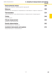
3.1. Control panel
The self-test lets you know if your printer is operating properly. It checks the
control circuits, printer mechanisms, print quality, ROM version, and DIP switch
settings.
You can control the basic paper feeding operations of the printer with the
button on the control panel. The indicator lights help you monitor the printer’s
status.
This test is independent of any other equipment or software.
Running the self test
Control Panel
1. Make sure the printer is turned off and the printer cover is closed properly.
2. While holding down the FEED button, turn on the printer using the switch on
the front of the printer to begin the self test. The Self Test prints the printer
settings and then prints the following,
Cuts the paper, and pauses. (Error LED On)
POWER
ERROR
PAPER
FEED
Self test Printing.
Please press the PAPER FEED button.
3. Press the FEED button to continue printing. The printer prints a pattern
using the built-in character set.
4. The self test automatically ends and cuts the paper after printing the
following:
Button
The button can be disabled by the ESC c 5 command.
*** completed ***
Press the FEED button once to advance paper one line. You can also hold
down the FEED button to feed paper continuously.
The printer is ready to receive data as soon as it completes the self-test.
3.2. Error indicator
This section explains the different patterns signaled by the two LED indicators
located on the top cover of the OM-9300.
LED3
LED2
LED1
RED
RED
GREEN
Power off
OFF
OFF
OFF
Power on
OFF
OFF
ON
On line
OFF
OFF
ON
Normal power is not supplied to
the printer
Normal power is supplied to the
printer
Normal error-free mode
Cover open
ON
ON
ON
Close cover
Paper empty
ON
ON
ON
Insert new paper roll
Test mode
OFF
OFF
ON
Ignored error led
STATUS
REMARKS
www.omniprintinc.com
17
18
www.omniprintinc.com
Chapter 5. Hexadecimal Dump
Chapter 6. Specifications
This feature allows experienced users to see exactly what data is coming to
the printer. This can be useful in finding software problems.
When you turn on the hex dump function, the printer prints all commands and
other data in hexadecimal format along with a guide section to help you find
specific commands.
6.1. General Specifications
To use the hex dump feature, follow these steps:
(3) Dot density
1. After you make sure that the printer is off and Dip sw 1-2 is ON, turn on the
printer.
2. Run any software program that sends data to the printer. The printer prints
“Hexadecimal Dump” and then all the codes it receives in a two-column
format. The first column contains the hexadecimal codes and the second
column gives the ASCⅡ characters that correspond to the codes.
Hexadecimal Dump
1B
21 00 1B 26
1B
25 01 1B 63
41
42 43 44 45
02
34
46
40
00
47
40
1B
48
.!..& . @ @
.%.. c4 ..
ABCDEFGH
(1) Printing Method
Direct line thermal printing.
(2) Print speed
Max. 920 dots/sec. (130mm/sec.)
180 DPI (Hor / Ver)
180 / 180 (0.142mm / 0.142mm dot)
203 DPI (Hor / Ver)
203 / 180 (0.125mm / 0.142mm dot)
(4) Printing Width
180 DPI
Max 72mm (512 dots)
203 DPI
Max 72mm (576 dots)
(5) Number of print columns
A period (.) is printed for each code that has no ASCII equivalent.
No. of Columns
3. Turn off the printer, and make sure that DIP switch 1-2 turns off.
4. Turn on the printer.
Font “A”
Font “B”
180 DPI
42
56
203 DPI
48
64
(6) Roll paper
Refer to chapter 2 for details on the recommended roll
Paper.
Paper width: 79.5 ± 0.5mm
Roll diameter: Ø80 mm or less
(7) Weight
1.76Kg
(8) Noise Approx. 55dB
www.omniprintinc.com
19
20
www.omniprintinc.com
(9) Overall dimension
(3) Power Connector
Important!
When using a printer power supply other than optional AC adaptor (HTU1135), be sure that the following cautions are observed.
Use a power supply of dc 24V±10% and more than 1.5A.
Be careful about installing the printer in an area where there is noise.
Take the appropriate measure to protect against electrostatic AC line Noise,
etc.
6.5. Environmental Requirements
(1) Operating
Temperature
5°C to 45°C
Humidity
10% to 90% RH (without condensation)
(2) Transport/Storage (except for paper)
Temperature
-20°C to 60°C
Humidity
10% to 90% RH (without condensation)
6.2. Auto Cutter Specifications
(1) Cutting Frequency
(2) Thickness of paper
6.6. Reliability
(1) MCBF
30 million lines (based on an average printing rate of12.5%
with paper thickness in the range 65µm to 75µm)
20 million lines (based on an average printing rate of 12.5%
with paper thickness in the range 76µm to 150µm)
Max. 30 cuts per minute
0.065 ~ 0.1 mm
6.3. Interface
RS232C serial interface, Centronics parallel interface, USB interface.
(IEEE1284)
(2) Head Life
6-4. Electrical Characteristics
(3) Cutter Life 1.0 million cuttings
(If the paper thickness is between 65 and100µm)
(1) Input Voltage
(2) Power Consumption
100 million pulses, 100Km
DC 24V ± 10%
Operating: Approx. 1.5 A (at ASC∥ printing)
Peak : Approx. 10 A
(at print duty 100%, For 10 seconds or less)
Stand-by : Approx. 0.15 A
www.omniprintinc.com
21
22
www.omniprintinc.com
Chapter 7. Command List
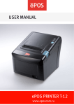
6.7. Black mark specifications
<Note>
1. The cut position shown above is adjustable.
2. The black mark’s PCS value must be 0.90 or more.
www.omniprintinc.com
23
24
No.
Command
Function
1
2
3
4
5
6
7
8
9
10
11
12
13
14
15
16
17
18
19
20
21
22
23
24
25
26
27
28
29
30
31
32
33
34
35
36
37
38
39
40
HT
LF
CR
FF
CAN
DLE EOT
DLE ENQ
DLE DC4
ESC FF
ESC SP
ESC !
ESC $
ESC %
ESC &
ESC *
ESC ESC 2
ESC 3
ESC =
ESC ?
ESC @
ESC D
ESC E
ESC G
ESC J
ESC L
ESC M
ESC R
ESC S
ESC T
ESC V
ESC W
ESC \
ESC a
ESC c 3
ESC c 4
ESC c 5
ESC d
ESC p
ESC t
Horizontal tab
Print and line feed
Print and carriage return
Print end position label to start printing
Cancel print data in page mode
Real-time status transmission
Real-time request to printer
Generate pulse at real-time
Print data in page mode
Set character right-side spacing
Set print mode
Select/cancel user-defined character set
Define user-defined characters
Turn underline mode on/off
Set bit image mode
Turn underline mode on/off
Set 1/6 inch line spacing
Set line spacing using minimum units
Select peripheral device
Cancel user-defined characters
Initialize printer
Set horizontal tab positions
Select emphasized mode
Select double-strike mode
Print end feed paper using minimum units
Select page mode
Select character font
Select international character set
Select standard mode
Select print direction in page mode
Set/cancel 90° cw rotated character
Set printing area in page mode
Set relative position
Align position
Select paper sensor(s) to output paper-end signals
Select paper sensor(s) to stop printing
Enable/disable panel buttons
Print and feed paper n lines
General pulse
Select character code table
www.omniprintinc.com
41
42
43
44
45
46
47
48
49
50
51
52
53
54
55
56
57
58
59
60
61
62
1
2
3
4
5
6
7
8
9
10
ESC {
FS p
FS q
GS !
GS $
GS *
GS /
GS B
GS H
GS I
GS L
GS P
GS V
GS W
GS \
GS a
GS f
GS h
GS k
GS r
GS v 0
GS w
< Add >
ESC i
ESC m
FS !
FS &
FS FS .
FS 2 c1
d1…dk
FS C
FS S 1 2
FS W
Appendix
Set/cancel upside-down character printing
Print NV bit image
Define NV bit image
Select character size
Set absolute vertical print position in page mode
Define downloaded bit image
Print down-loaded bit image
Turn white/black reverse printing mode on/off
Select printing position of HRI characters
Transmit printer ID
Set left margin
Set horizontal and vertical motion units
Cut paper
Set printing area width
Set relative vertical print position in page mode
Enable/disable Automatic Status Back(ASB)
Select font for HRI characters
Set bar code height
Print bar code
Transmit status
Print raster bit image
Set bar code width
A.1 Ordering information
Basic Model Name
00 = Ivory color
10 = Black color
S = Serial interface
P = Parallel interface
U = USB interface
OM-93(
)(
)
[Example]
OM-9310P = Black color parallel interface printer
A.2 Printer mechanism handling
1) Do not pull the paper out when the cover is closed.
2) Because the thermal elements of the print head and driver ICs are easy to
break, do not touch them with any metal objects.
3) Since the areas around the print head become very hot during and just
after printing, do not touch them.
4) Do not use the cover open button except when necessary.
5) Do not touch the surface of the print head because bust and dirt can stick
to the surface and damage the elements.
6) Thermal paper containing Na, K, Cl ions can harm the print head thermal
elements. Therefore, be sure to use only the specified paper.
Full cut
Partial cut
Set print mode(s) for Kanji characters
Select Kanji character mode
Turn underline mode on/off for Kanji character
Cancel Kanji character mode
Define user-defined Kanji characters
Select Kanji character code system
Set left-and right-side Kanji character spacing
Turn quadruple-size mode on/off for Kanji character
A.3 Thermal paper handling
Notes on using thermal paper
Chemicals and oil on thermal paper may cause discoloration and faded
printing. Therefore, pay attention to the following;
1) Use water paste, starch paste, polyvinyl paste, or CMC paste when gluing
thermal paper.
2) Volatile organic solvents such as alcohol, ester, and ketone can cause
discoloration.
3) Some adhesive tapes may cause discoloration or faded printing.
www.omniprintinc.com
25
26
www.omniprintinc.com
4) If thermal paper touches anything that includes phthalic acid ester
plasticizer for a long time, it can reduce the image formation ability of the
paper and can cause the printed image to fade. Therefore, when storing
thermal paper in a card case or sample notebook, be sure to use only
products made from polyethylene, polypropylene, or polyester.
5) If thermal paper touches diazo copy paper immediately after copying, the
printed surface may be discolored.
6) Thermal paper must not be stored with the printed surfaces against each
other because the printing may be transferred between the surfaces.
7) If the surface of thermal paper is scratched with a hard metal object such
as a nail, the paper may become discolored.
Notes on thermal paper storage
Since color development begins at 70°C (158°F), thermal paper should be
protected from high temperature, humidity, and light, both before and after
printing.
1) Store paper away from high temperature and humidity. Do not store
thermal paper near a heater or in enclosed places exposed to direct
sunlight.
2) Avoid direct sunlight. Extended exposure to direct light may cause
discoloration or faded printing.
www.omniprintinc.com
27
28
www.omniprintinc.com