1
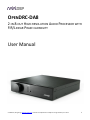
OPENDRC-DA8
2-IN 8-OUT HIGH-RESOLUTION AUDIO PROCESSOR WITH
FIR/LINEAR PHASE CAPABILITY
User Manual
miniDSP Ltd, Hong Kong / www.minidsp.com / Features and specifications subject to change without prior notice
1
Revision history
Revision
V0.1
V1.0
Description
Preliminary version
First release version
Date
21 August 2015
8 September 2015
miniDSP Ltd, Hong Kong / www.minidsp.com / Features and specifications subject to change without prior notice
2
CONTENTS
Important Information......................................................................................................................................... 5
System Requirements ...................................................................................................................................... 5
Disclaimer/Warning ......................................................................................................................................... 5
Warranty Terms ............................................................................................................................................... 6
FCC Class B Statement...................................................................................................................................... 6
CE Mark Statement .......................................................................................................................................... 6
A note on this manual ...................................................................................................................................... 6
1 Product Overview .......................................................................................................................................... 7
1.1
Typical usage ........................................................................................................................................ 7
1.2
The miniDSP concept ............................................................................................................................ 8
1.3
Choosing a plugin ................................................................................................................................. 8
2 The miniDSP workflow................................................................................................................................... 9
3 Installation and setup .................................................................................................................................. 11
3.1
Software installation .......................................................................................................................... 11
3.1.1
Windows .................................................................................................................................... 11
3.1.2
Mac OS X .................................................................................................................................... 12
3.2
Hardware connectivity ....................................................................................................................... 13
3.2.1
Digital input ................................................................................................................................ 13
3.2.2
Analog outputs ........................................................................................................................... 13
3.2.3
DC power.................................................................................................................................... 14
3.2.4
USB............................................................................................................................................. 14
3.3
Synchronizing with the processor ....................................................................................................... 15
4 Configuring the processor............................................................................................................................ 16
4.1
Input tab ............................................................................................................................................ 17
4.2
Routing tab......................................................................................................................................... 18
4.3
Output tab ......................................................................................................................................... 19
4.3.1
Channel strip layout .................................................................................................................... 20
4.3.2
Channel label .............................................................................................................................. 20
4.3.3
Gain control and level monitoring ............................................................................................... 20
4.3.4
Crossover.................................................................................................................................... 21
4.3.5
Parametric EQ............................................................................................................................. 23
4.3.6
FIR .............................................................................................................................................. 25
4.3.7
Invert and mute .......................................................................................................................... 25
4.3.8
Time delay .................................................................................................................................. 25
4.3.9
Compressor ................................................................................................................................ 26
4.4
Custom biquad programming ............................................................................................................. 27
4.4.1
What’s a “biquad? ...................................................................................................................... 27
4.4.2
Using custom biquad programming ............................................................................................ 27
4.4.3
Biquad design software............................................................................................................... 29
4.5
FIR filtering and design ....................................................................................................................... 30
4.5.1
FIR filtering overview .................................................................................................................. 31
miniDSP Ltd, Hong Kong / www.minidsp.com / Features and specifications subject to change without prior notice
3
4.5.2
FIR filter design software ............................................................................................................ 31
4.5.3
Filter file format.......................................................................................................................... 31
4.5.4
Loading filter coefficients ............................................................................................................ 32
4.6
Working with configurations .............................................................................................................. 33
4.6.1
Online and offline mode ............................................................................................................. 33
4.6.2
Selecting a configuration ............................................................................................................ 33
4.6.3
Saving and loading configurations ............................................................................................... 34
4.6.4
Restoring to defaults................................................................................................................... 34
4.7
Keyboard shortcuts ............................................................................................................................ 35
5 Using the OpenDRC-DA8 ............................................................................................................................. 36
5.1
Status indicators ................................................................................................................................. 36
5.2
Front panel controls ........................................................................................................................... 36
5.3
Infrared remote control ...................................................................................................................... 37
6 Additional information ................................................................................................................................ 38
6.1
Specifications ..................................................................................................................................... 38
6.2
Troubleshooting ................................................................................................................................. 38
6.3
MCU firmware update ........................................................................................................................ 40
6.4
Obtaining support .............................................................................................................................. 41
miniDSP Ltd, Hong Kong / www.minidsp.com / Features and specifications subject to change without prior notice
4
IMPORTANT INFORMATION
Please read the following information before use. In case of any questions, please contact miniDSP via the
support portal at minidsp.desk.com.
SYSTEM REQUIREMENTS
To configure the miniDSP audio processor, you will require a Windows PC or Apple Mac OS X computer with the
following minimum specification:
Windows
PC with 1GHz or higher processor clock speed. Intel® Pentium®/Celeron® family, or AMD K6®/AMD
Athlon®/AMD Duron® family, or compatible processor recommended.
512 megabytes (MB) of RAM or higher
Keyboard and mouse or compatible pointing device
USB 2.0 port
Microsoft• ® Windows® Vista® SP1/ XP pro SP2/Win7/Win8.1
Microsoft• ® .NET framework v3.5 or later
Adobe AIR environment (latest version)
Adobe Flash player (latest version)
Mac OS X
Intel-based Mac with 1 GHz or higher processor clock speed
512 megabytes (MB) of RAM or higher
Keyboard and mouse or compatible pointing device
USB 2.0 port
Mac OS X 10.4 or higher
Adobe AIR environment (latest version)
Adobe Flash player (latest version)
DISCLAIMER/WARNING
miniDSP cannot be held responsible for any damage that may result from the improper use of this product or
incorrect configuration of its settings. As with any other product, we recommend that you carefully read this
manual and other technical notes to ensure that you fully understand how to operate this product. The miniDSP
audio processor is a powerful tool, and misuse or misconfiguration, such as incorrectly set gains or excessive
boost, can produce signals that may damage your audio system.
As a general guideline, you should perform the initial configuration of the miniDSP audio processor before
enabling audio through any connected output device or amplification. Doing so will help ensure that the
software is correctly configured.
miniDSP Ltd, Hong Kong / www.minidsp.com / Features and specifications subject to change without prior notice
5
Finally, note that the miniDSP audio processor is a very flexible device, and many of the questions we receive at
the tech support department are already answered in this user manual and in the online application notes on
the miniDSP.com website. So please take the time to carefully read this user manual and the online technical
support. Thanks for your understanding!
WARRANTY TERMS
miniDSP Ltd warrants this product to be free from defects in materials and workmanship for a period of one
year from the invoice date. Our warranty does not cover failure of the product due to incorrect connection or
installation, improper or undocumented use, unauthorized servicing, modification or alteration of the unit in any
way, or any usage outside of that recommended in this manual. If in doubt, contact miniDSP prior to use.
FCC CLASS B STATEMENT
This device complies with Part 15 of the FCC Rules. Operation is subject to the following two conditions:
This device may not cause harmful interference.
This device must accept any interference received, including interference that may cause undesired
operation.
Warning: This equipment has been tested and found to comply with the limits for a Class B digital device,
pursuant to Part 15 of the FCC Rules. These limits are designed to provide reasonable protection. This
equipment generates, uses and can radiate radio frequency energy and, if not installed and used in accordance
with the instructions, may cause interference to radio communications. However, there is no guarantee that
interference will not occur in a particular installation. If this equipment does cause harmful interference to radio
or television reception, which can be determined by turning the equipment off and on, the user is encouraged to
try to correct the interference by one or more of the following measures:
Reorient or relocate the receiving antenna.
Increase the separation between the equipment and receiver.
Connect the equipment into an outlet on a circuit different from that to which the receiver is connected.
Consult the dealer or an experienced radio/TV technician for help.
Notice: Shielded interface cable must be used in order to comply with emission limits.
Notice: Changes or modification not expressly approved by the party responsible for compliance could void the
user’s authority to operate the equipment.
CE MARK STATEMENT
The OpenDRC-DA8 has passed the test performed according to European Standard EN 55022 Class B.
A NOTE ON THIS MANUAL
This User Manual is designed for reading in both print and on the computer. If printing the manual, please print
double-sided. The embedded page size is 8 ½” x 11”. Printing on A4 paper will result in a slightly reduced size.
miniDSP Ltd, Hong Kong / www.minidsp.com / Features and specifications subject to change without prior notice
6
1 PRODUCT OVERVIEW
Thank you for choosing the miniDSP OpenDRC-DA8 audio processor. The miniDSP OpenDRC-DA8 is a powerful
and flexible high-resolution1 digital audio processor for active crossover and other audio processing applications.
It features:
Stereo digital S/PDIF input (via RCA connector) and eight analog output channels (RCA)
Choice of 48 kHz and 96 kHz plugins
Parametric EQ on all input and output channels, Butterworth and Linkwitz-Riley crossovers up to 48
dB/octave, and advanced biquad programming for an unlimited range of filters and crossover types
FIR filtering on every output channel, with taps per channel assignable up to a total of 9600 taps (48 kHz
plugin) or 3400 taps (96 kHz plugin)
Matrix mixer for flexible channel assignment and configuration
Real-time configuration of all processing parameters
Volume control by front panel or infrared remote
Four on-board presets, selectable from front panel or by infrared remote
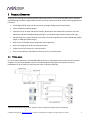
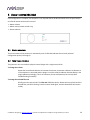
1.1 TYPICAL USAGE
In its most typical application, the OpenDRC-DA8 connects to a single digital source and directly drives power
amplifiers in an active loudspeaker system. The onboard FIR filtering supports linear phase crossovers.
Loudspeakers of up to 4-way (or three-way plus subs) are directly supported.
1
With the 96 kHz plugin, the processor operates at 24-bit resolution and 96 kHz internal sample rate.
miniDSP Ltd, Hong Kong / www.minidsp.com / Features and specifications subject to change without prior notice
7
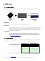
1.2 THE MINIDSP CONCEPT
The miniDSP concept is “one hardware unit + one software plugin = audio processing solution.” This concept
leverages the inherent flexibility of DSP (digital signal processing) to deliver a range of flexible but cost-effective
solutions.
Hardware unit
In this case, the hardware unit is the miniDSP OpenDRC-DA8.
Software plugin
The software plugin is installed on your PC or Mac, and determines the processing that the DSP
will perform. It provides a friendly user interface, and downloads instructions into the miniDSP
hardware unit that tell it how to process the audio signal. Currently, the OpenDRC-DA8 supports
two plugins, as described below.
Other platforms
miniDSP makes many other boxed and kit hardware units with analog, stereo digital, and
multichannel digital (HDMI) connections. Some units feature inbuilt Class D amplification. See
the full range of miniDSP products.
1.3 CHOOSING A PLUGIN
Two plugins are currently available for the OpenDRC-DA8: the miniSHARC 4x8 and the miniSHARC 4x8 96k. The
table below summarizes the key differences between these plugins when used with the OpenDRC-DA8 (some
parameters are the same, but are included to show that they do not change with the plugin):
Number of digital input channels1
Number of analog output channels
Digital input sample rate
Internal sample rate
Total number of FIR taps
Number of PEQ bands per block
Compressor block
Maximum per-channel time delay
miniSHARC 4x8 plugin
2
8
20 to 216 kHz
48 kHz
9600
10
Yes
3000 ms
miniSHARC 4x8 96k plugin
2
8
20 to 216 kHz
96 kHz
3400
10
Yes
1500 ms
*1 two channels = single stereo digital signal
miniDSP Ltd, Hong Kong / www.minidsp.com / Features and specifications subject to change without prior notice
8
2 THE MINIDSP WORKFLOW
We strongly recommend taking a methodical approach to your new miniDSP audio processor. Remember that
the audio processor is a powerful tool and incorrect settings can potentially cause damage to your system.
Please follow the steps below carefully.
1. Download and install the plugin
When your order ships, your ordered plugin (or plugins) will be available from the User
Downloads section of the miniDSP website. Download and install your plugin, as described in
Software installation on page 11.
2. Familiarize yourself with the plugin
Before connecting your computer to the processor, it’s worth starting the plugin and
familiarizing yourself with its user interface. Click on and explore each of the tabs (Input,
Routing, and Output). For more information, see Configuring the processor starting on page 16.
At this time, the plugin is still in offline mode, so any changes you make will not be downloaded
into the miniDSP hardware. Since we will reset all of the processing parameters in the next step,
you can feel free to experiment at this point.
3. Reset all parameters
From the Restore menu, select the Factory Default option. This will reset all processing
parameters back to the defaults and ensure that you have a "clean slate" for the next step.
4. Perform initial configuration
Use the plugin to set up an initial audio processing configuration as intended for your
application. For example, typical things that can be done at this point are to:
Set the labels of input and output channels
Mute unused input and output channels
Set crossover frequencies and slopes
Set up any essential equalization
5. Save configuration
At this point, save your initial configuration to a file. A configuration is the set of all audio
processing parameters. You should save your configuration to a file on a regular basis, to ensure
that you do not lose your work if you inadvertently restore the processor to default settings. For
more information on configurations, see Working with configurations on page 33.
6. Make audio connections
With the initial configuration done and now that you are familiar with the various controls, it’s
time to connect the miniDSP OpenDRC-DA8 into your system. Ensure that all power is turned off
when making audio connections. See Hardware connectivity on page 13.
miniDSP Ltd, Hong Kong / www.minidsp.com / Features and specifications subject to change without prior notice
9
7. Go into online mode
Apply power to the processor. (See DC power on page 14 for more information. Leave other
equipment turned off at this stage.) Connect the USB cable to your computer, click on the
Connect&Synchronize button, and select the Synchronize option. If all goes well, you are now in
online mode, and any changes that you now make in the plugin user interface will be
immediately sent to the processor.
Before proceeding, click on each Configuration preset button (Config 1, 2, etc.) to ensure that all
presets have been synchronized and/or set to defaults.
For more information, see Synchronizing with the processor on page 15.
8. Initial audio check
Power on your connected equipment, first on the input side (e.g. source or preamp), then on the
output side (e.g. power amps). Turn the volume on your OpenDRC-DA8 down low (view the
Master Volume display in the plugin while turning the knob counter-clockwise) and start playing
music or a pink noise test signal. Gradually increase the volume until your hear audio quietly
coming from the speakers. Verify that the plugin is performing the intended function. (For
example, if implementing a two-way crossover, confirm that the tweeter is playing high
frequencies, and that the woofer is playing low frequencies.)
9. Fine-tune your configuration
With your initial setup running, you can now proceed to fine-tune and optimize your system.
You will need to perform acoustic measurements and use the configuration screens to adjust
processing parameters.
Be sure to save your configuration on a regular basis while working on fine-tuning it.
Configurations can be saved to different files, in order to archive different versions, or to enable
auditioning of alternative configurations.
10. Continue to operate offline
With your miniDSP processor configured, you can continue to operate in offline mode—that is,
without the computer connected. To do so, simply disconnect the USB cable. The processor
“remembers” the configuration last set, and will continue to operate without the computer.
Note: while in offline mode, the configuration can still be modified in the plugin interface. These
changes will not be downloaded to the processor until it is synchronized again. See Working with
configurations on page 33.
miniDSP Ltd, Hong Kong / www.minidsp.com / Features and specifications subject to change without prior notice
10
3 INSTALLATION AND SETUP
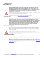
3.1 SOFTWARE INSTALLATION
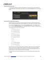
When your order ships, your ordered plugin (or plugins) will be available from the User Downloads section of
the miniDSP website. You will need to be logged into the website with the account you created when
purchasing. The User Downloads link is visible from the dropdown menu at the top right of the website page:
Navigate to the OpenDRC Plug-ins section of User Downloads, then download the zip file (or files) under the
heading miniSHARC 4x8 48k and/or miniSHARC 4x8 96k. Double-click on it to unzip it. Then follow the
installation procedure below according to your computer type.
Note: the Adobe Air framework may need a network connection the first time the plugin is used. If the plugin
does not start properly, see Troubleshooting.
3.1.1
Windows
Prior to installing the miniDSP software, download and install the following programs. You will need to accept
the license agreements in order to successfully complete the installation.
Microsoft .NET framework (version 3.5 or later)
Latest version of Adobe Flash
Latest version of Adobe Air
If you haven’t updated these recently, you should download and install the latest versions prior to running the
miniDSP install program.
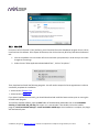
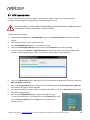
To install the miniDSP software, open the Windows folder of the download and double-click on the
miniSHARC_4x8.exe or miniSHARC_4x8_96k.exe program. We recommend accepting the default installation
settings. Once installation is complete, the plugin will automatically start. Since the plugin checks for a network
connection when starting up, a warning such as the following may appear. In this case, click on Allow access.
miniDSP Ltd, Hong Kong / www.minidsp.com / Features and specifications subject to change without prior notice
11
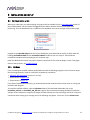
3.1.2
Mac OS X
On versions of OS X from 10.7 (Lion) and later, you will need to inform the GateKeeper program that it is OK to
install and run this software. Go to System Preferences, then click on Security & Privacy and select the General
tab:
1. Click on the padlock icon in the lower left corner and enter your password, in order that you can make
changes to the settings.
2. Under the text “Allow Applications downloaded from:”, click on “Anywhere.”
Then, download and install the following programs. You will need to accept the license agreements in order to
successfully complete the installation:
Latest version of Adobe Flash
Latest version of Adobe Air
If you haven’t updated these recently, you should download and install the latest versions prior to running the
miniDSP install program.
To install the miniDSP software, open the Mac folder of the download, and double-click on the miniSHARC4x8.dmg of miniSHARC-4x8_96k.dmg file to open it in a new window. Then double-click on the installer
program, Install miniSHARC 4x8.app or Install miniSHARC 4x8 96k.app. Once installation is complete, the plugin
will automatically start.
miniDSP Ltd, Hong Kong / www.minidsp.com / Features and specifications subject to change without prior notice
12
3.2 HARDWARE CONNECTIVITY
All connections to the OpenDRC-DA8 are made on the rear panel.
3.2.1
Digital input
Connect a single digital source to the S/PDIF coax (RCA) connector.
Note: the digital input accepts only a stereo PCM digital signal. It does not accept encoded or multichannel
digital audio (such as Dolby Digital or DTS).
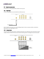
3.2.2
Analog outputs
There are eight analog output channels. Unbalanced connections are made directly from the RCA jacks to power
amplifiers. Be sure to take careful note of the channel numbering shown in this diagram and on the rear panel.
miniDSP Ltd, Hong Kong / www.minidsp.com / Features and specifications subject to change without prior notice
13
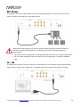
3.2.3
DC power
The supplied 5 VDC power supply includes a set of interchangeable power pins. Fit the correct pins for your
country. Connect the DC plug to the 5 VDC power socket.
Apply power to the processor only after all input and output connections have been made. The
processor can usually be left powered on. If powered on and off, the following sequence is
recommended:
On: Power on line-level equipment, including the OpenDRC-DA8, then turn on power amplification.
Off: Turn power amplification off, then power off line-level equipment, including the OpenDRCDA8.
3.2.4
USB
To configure the processor, connect its USB port to a USB 2.0 port on your computer using the supplied cable.
Note that USB is used only for configuration—audio data cannot be streamed to the processor over USB.
miniDSP Ltd, Hong Kong / www.minidsp.com / Features and specifications subject to change without prior notice
14
3.3 SYNCHRONIZING WITH THE PROCESSOR
Communication with the processor takes place over a USB connection. Note that USB is used for control
purposes only. Audio data cannot be streamed to the processor over USB.
Ensure that the computer is connected to the processor by a USB 2.0 port. Then click on the
Connect&Synchronize button:
The first time you connect, or if you have made any changes to any data in the user interface, the following
dialog box will appear:
The options are:
Synchronize Config
Download the currently selected configuration into the corresponding configuration preset of
the processor. After downloading the configuration data, the plugin is in online mode and any
changes to processing parameters will be downloaded immediately in real time. That is, the user
interface is now “live.”
Synchronize and Upgrade
This is similar to Synchronize Config, but also upgrades the internal data of the processor. This
option may appear after downloading and installing an updated version of the plugin.
Restore Config
Restore the data in the currently selected configuration to the factory defaults. When using this
option, any connected equipment should be muted or powered off until you have set the
configuration to a working state. Note that the configuration data will be lost, so if needed,
ensure that you have saved the configuration to a file prior to using this option.
Cancel
This option cancels the attempt to connect to the processor. The plugin will remain in offline
mode.
miniDSP Ltd, Hong Kong / www.minidsp.com / Features and specifications subject to change without prior notice
15
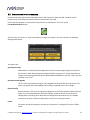
4 CONFIGURING THE PROCESSOR
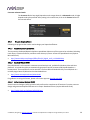
The OpenDRC-DA8 processor is configured with the miniSHARC 4x8 or miniSHARC 4x8 96k plugin / user
interface program. Once fully configured, the computer is no longer required, as source and preset selection can
be done with the front panel or a remote control—see Using the OpenDRC-DA8. If desired, however, the plugin
can remain connected during use for real-time (“live”) control of all audio processing.
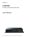
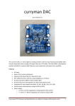
This screenshot shows the miniSHARC 4x8 plugin with the key areas highlighted:
During initial configuration of the processor, it is strongly recommended that any connected
amplification be muted or powered off.
The Mute button disables all audio output:
The Master volume display shows the current volume setting:
miniDSP Ltd, Hong Kong / www.minidsp.com / Features and specifications subject to change without prior notice
16
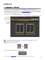
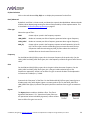
4.1 INPUT TAB
The Input tab displays a row of input channel control strips. When the miniSHARC 4x8 plugin is used with the
OpenDRC-DA8, only the two rightmost channels (labeled SPDIF Input) receive signal:
Channel label
Each input channel has a customizable
label, which is shown at the top of the
channel strip. This label also appears on
the Routing tab. To change the label, click
on it, type a new label (up to eight
characters), and press the Return key.
Level meter
Displays the current signal level in real
time. (The plugin must be in online mode
to display signal levels.)
Gain adjustment
The gain of each channel can be adjusted by moving the Gain Adjustment slider, or by typing the
desired gain into the Current Gain text box. The maximum gain setting is 12 dB, and the
minimum gain setting is –72 dB. (0 dB, the default, is unity gain or no change in level.)
PEQ settings
Click on this button to open the parametric EQ settings window for that channel. There are ten
parametric EQ filters on each input channel. For more details, see Parametric EQ on page 23.
Mute
Press this button to mute that input channel. A visual indicator shows that the channel is muted.
miniDSP Ltd, Hong Kong / www.minidsp.com / Features and specifications subject to change without prior notice
17
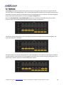
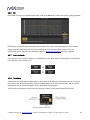
4.2 ROUTING TAB
The Routing tab displays the matrix mixer, which sets up the routing from input channels to output channels.
The input channels are labeled along the left, and the output channels along the top. Each input-output channel
assignment is turned on and off by clicking the button corresponding to the two channels. (The labels displayed
for the input and output channels are set up in the Input and Output tabs.)
When the miniSHARC 4x8 and miniSHARC 48 96k plugins are used with the OpenDRC-DA8, only the SPDIF
inputs are active. We recommend that the I2S inputs be unrouted, as shown here:
To make the routing matrix easier to view, the labels of the input and output channels can be changed in the
Input and Output tabs, resulting in:
The above example is a typical routing matrix for 4-way loudspeaker. If more than one input signal is routed to
an output channel, those channels are mixed together (summed). Here is another common routing matrix, for a
stereo 3-way crossover and a pair of summed subwoofer outputs:
miniDSP Ltd, Hong Kong / www.minidsp.com / Features and specifications subject to change without prior notice
18
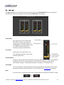
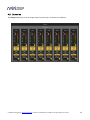
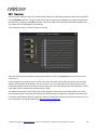
4.3 OUTPUT TAB
The Output tab displays a row of output channel control strips. All channels are identical.
miniDSP Ltd, Hong Kong / www.minidsp.com / Features and specifications subject to change without prior notice
19
4.3.1
Channel strip layout
Each output channel has a complete "strip" of controls.
4.3.2
Channel label
Each output channel has a customizable label, which is shown at the top of the channel strip. This label also
appears on the Routing tab. To change the label, click on it, type a new label (up to eight characters), and press
the Return key.
4.3.3
Gain control and level monitoring
Level meter
Displays the current signal level in real time. (The plugin must be in online mode to display signal
levels.)
Gain adjustment
The gain of each channel can be adjusted by moving the Gain Adjustment slider, or by typing the
desired gain into the Current Gain text box. The maximum gain setting is 12 dB, and the
minimum gain setting is –72 dB. (0 dB, the default, is unity gain or no change in level.)
The level meters are useful in many situations. For example, when adding filters with boost, monitor the level
meters with typical signals and maximum levels to ensure that there is no clipping. The meters can also be used
during normal operation to monitor for or to help locate level or gain structure problems.
miniDSP Ltd, Hong Kong / www.minidsp.com / Features and specifications subject to change without prior notice
20
4.3.4
Crossover
Each output channel has independent high pass and low pass filters. Click on the Xover button to open the
crossover settings window:
Crossovers “split” the frequency band to send to different drivers. In a two-way loudspeaker, for example, a low
pass filter is used to remove high frequencies from the signal sent to the woofer, and a high pass filter is used to
remove low frequencies from the signal sent to the tweeter. In a three-way speaker, the midrange driver will
use both the high pass and low pass filters. Crossover filters can also be used to limit low frequency content
delivered to a speaker or subwoofer, to help protect it from over-excursion.
Unlike conventional analog crossovers, the flexibility of DSP allows a completely arbitrary mix of different filter
slopes and types. Filters can be set at any frequency, or disabled completely. This allows maximum flexibility in
matching your crossover to the acoustic characteristics of the loudspeaker drivers.
Crossover filters are displayed in two groups of four—channels 1 through 4, and channels 5 though 8. Each
group is configured by default as a four-way crossover. The current channel is displayed in orange, with the
other three in the group in grey.
Hovering the mouse over the curve brings up an overlay
showing the frequency and the attenuation at that frequency.
miniDSP Ltd, Hong Kong / www.minidsp.com / Features and specifications subject to change without prior notice
21
Basic/Advanced
By default, the crossover is in basic mode, and shows the controls described below. Advanced
mode enables custom biquad programming for almost infinite flexibility in crossover filter
implementation. This is described in Custom biquad programming on page 27.
Cutoff Frequency
Sets the nominal cutoff frequency of the crossover. In actual fact, the crossover has a more or
less gradual transition from “full on” to “full off,” as determined by the filter slope.
Filter type
Selects the type and slope of the filter. The steeper the slope, the more quickly frequencies
above or below the cutoff frequency are attenuated. There are three types of filter:
Butterworth (BW)
Available in 6, 12, 18, 24, 30, 36, 42, and 48 dB/octave, Butterworth crossover
filters are 3 dB down at the cutoff frequency.
Linkwitz-Riley (LR)
Available in 12, 24, 36, and 48 dB/octave, Linkwitz-Riley crossover filters are 6 dB
down at the cutoff frequency.
Bessel
Available in 12 dB/octave only, a Bessel filter gives a more gradual roll-off
through the crossover region.
Bypass
Clicking on the Bypass button disables or enables that high pass
or low pass filter. The filter is bypassed when the button is "lit".
Each channel can be linked to one other channel. When a channel is linked to another, the crossover settings of
that channel are mirrored to the other. Typically, the corresponding drivers on the left and right channels are
linked: left and right tweeter, left and right woofer, and so on. To link a channel, select the other channel from
the drop-down menu at the top left of the Xover screen, and click the Link checkbox.
miniDSP Ltd, Hong Kong / www.minidsp.com / Features and specifications subject to change without prior notice
22
4.3.5
Parametric EQ
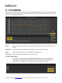
Parametric equalization (PEQ) is a flexible type of equalization filter. It can be used to correct for errors in
loudspeaker output, to compensate for acoustic room effects, and to tailor the overall system response for best
sound. Click on the PEQ button to open the parametric equalizer settings window:
There are ten parametric EQ filters on each input and output channel. The window displays a frequency
response graph showing the combined response of all enabled parametric filters on that channel. For example,
the screenshot above shows a response curve created with a low-shelf boost filter at 100 Hz, a dip at 500 Hz,
and a high-shelf cut filter at 5000 Hz.
Hovering the mouse over the curve brings up an overlay showing the frequency and the gain at that frequency.
Each channel can be linked to one other channel. When a channel is linked to another, the PEQ settings of that
channel are mirrored to the other. Typically, the corresponding drivers on the left and right channels are linked:
left and right tweeter, left and right woofer, and so on. To link a channel, select the other channel from the
drop-down menu at the top left of the PEQ screen, and click the Link checkbox.
miniDSP Ltd, Hong Kong / www.minidsp.com / Features and specifications subject to change without prior notice
23
EQ band selection
Click on the radio buttons EQ1, EQ2, etc. to display the parameters for that filter.
Basic/Advanced
By default, each filter is in basic mode, and shows the controls described below. Advanced mode
enables custom biquad programming for almost infinite flexibility in filter implementation. This
is described in Custom biquad programming on page 27.
Filter type
Selects the type of filter:
PEAK
Create a dip or a peak in the frequency response.
LOW_SHELF
Reduce or increase part of the frequency spectrum below a given frequency.
HIGH_SHELF
Reduce or increase part of the frequency spectrum above a given frequency.
SUB_EQ
Create a dip or a peak in the frequency response at low frequencies (10 to 50
Hz). This filter type is similar to PEAK but gives more accurate results for low
frequencies. Note that activating any SUB_EQ filter reduces the number of
available filters on that channel from ten to nine.
Frequency
For the PEAK and SUB_EQ filter types, this is the center frequency of the peak or dip. For the
HIGH_SHELF and LOW_SHELF filter types, this is the frequency at which the gain is half of the set
value.
Gain
For the PEAK and SUB_EQ filter types, this is the gain in dB at the center frequency. For the
HIGH_SHELF and LOW_SHELF filter types, this is the gain in dB reached at high or low
frequencies respectively. A filter has no effect if its gain is set to 0 dB. Gain can be adjusted in
increments of 0.1 dB up to +/- 16 dB.
Q
Q controls the “sharpness” of the filter. For the PEAK and SUB_EQ filter types, lower Q gives a
broader peak or dip, while higher Q gives a narrower peak or dip. For the HIGH_SHELF and
LOW_SHELF filter types, Q controls how quickly the filter transitions from no gain to maximum
gain.
Bypass
The Bypass button enables or disables a filter. The filter is
bypassed if the button is "lit". (Note that all other filters are
still operational unless individually bypassed.) A filter will also
have no effect if its gain is set to 0.0.
miniDSP Ltd, Hong Kong / www.minidsp.com / Features and specifications subject to change without prior notice
24
4.3.6
FIR
Each output channel has a variable-tap FIR filter. Click on the FIR button to open the FIR filter settings window:
FIR filtering is a powerful feature that allows very complex filters to be constructed (with the aid of suitable
design software). These filters can correct for amplitude only ("linear phase filters"), phase only, or a
combination or both. FIR filtering is described in detail in FIR filtering and design, starting on page 30.
4.3.7
Invert and mute
Each channel can be inverted in polarity, and individually muted. When either of these options is selected, the
visual indicator on the button is "lit":
4.3.8
Time delay
A delay of up to 1500 or 3000 ms (depending on the plugin) can be applied to each output channel. To set the
delay, click in the delay entry box for a channel. The delay value can be entered numerically, and the up and
down arrows can be used to change the delay in small (0.02 ms) increments.
The time delay corresponds to a distance. This distance is shown in centimeters below the entry box.
miniDSP Ltd, Hong Kong / www.minidsp.com / Features and specifications subject to change without prior notice
25
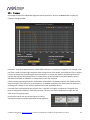
4.3.9
Compressor
The compressor reduces the gain of an output channel when the audio signal reaches a certain level as specified
by the Threshold parameter. The gain of the channel will be progressively reduced as the signal increases above
the threshold, according to the Ratio parameter. This can be used to limit the power delivered to speakers and
thus reduce the risk of damage from overdriving.
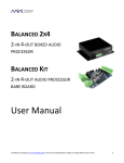
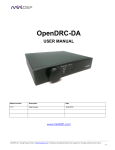
This screenshot shows an example Compressor setting:
(Note that the compressor algorithm is bypassed by default, so click on the Bypass button to see the curve as
shown here.)
In this example, the threshold is set to -20 dB, so the compressor will activate when the signal on that channel
reaches -20 dB (relative to full output). The ratio is set to 2, so if the input signal level to the compressor then
increases by 10 dB, the output level will increase by only 5 dB. If the input signal level to the compressor is at full
scale (0 dB), then the output level will be limited to -10 dB.
Two additional parameters control the action of the compressor: the attack time and the release time. These
two parameters govern how quickly the compressor activates when the signal level exceeds the threshold, and
how quickly it deactivates when the signal level reduces. The optimum settings may need to be tuned by ear. For
more information, see the Wikipedia article Dynamic range compression.
miniDSP Ltd, Hong Kong / www.minidsp.com / Features and specifications subject to change without prior notice
26
4.4 CUSTOM BIQUAD PROGRAMMING
Custom biquad programming is available in the PEQ and Crossover blocks. Its purpose is to allow you to directly
provide the low-level parameters aka biquad coefficients that control the digital filters of the processor, thus
providing an almost infinite degree of flexibility.
For example, you can create hybrid crossovers with staggered cutoff frequencies, create parametric EQ filters
beyond those provided in the easy-to-use “basic” interface, implement a Linkwitz transform, or mix crossover
and EQ biquads in the same block.
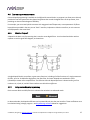
4.4.1
What’s a “biquad?
A biquad is the basic unit of processing that is used to create digital filters. It can be described either with an
equation or with a signal flow diagram, as shown here:
A single biquad like this can perform a great many functions, including all of the functions of a single parametric
EQ filter, one 6 or 12 dB/octave high pass or low pass filter, and more. Biquads are combined in series
(cascaded) to create more complex filters. The function that each biquad performs is determined by just five
numbers: a1, a2, a0, b1, and b2. These numbers are called the coefficients.
4.4.2
Using custom biquad programming
Each crossover block and PEQ filter has a selector that switches it to advanced mode:
In advanced mode, the biquad coefficients can be pasted directly into the user interface. These coefficients must
be calculated using a design program – see Biquad design software below for suggestions.
miniDSP Ltd, Hong Kong / www.minidsp.com / Features and specifications subject to change without prior notice
27
Parametric EQ advanced mode
In the parametric EQ blocks, advanced mode allows each individual filter to be specified by its
biquad coefficients. After pasting in the coefficients, click on the Process button for them to take
effect.
Parametric EQ file import (REW integration)
Multiple biquads in the parametric EQ block can be set at once by importing a coefficient file.
This file can be generated by Room EQ Wizard (REW) or by other programs. The design program
must be set for a 48 kHz sample rate if using the miniSHARC 4x8 plugin, and a 96 kHz sample
rate if using the miniSHARC 4x8 96k plugin. The number of filters is limited to a maximum of ten.
This example illustrates the correct file format:
biquad1,
b0=0.998191200483864,
b1=-1.9950521500467384,
b2=0.996920046761057,
a1=1.9950521500467384,
a2=-0.9951112472449212,
biquad2,
b0=0.999640139948623,
b1=-1.9981670485581222,
b2=0.9985489719847982,
a1=1.9981670485581222,
a2=-0.9981891119334211,
biquad3,
...
biquad4,
...
biquad5,
b0=1.0010192374642126,
b1=-1.9950555192569264,
b2=0.9940580112181501,
a1=1.995060938714333,
a2=-0.9950718292249559
Note that the last line must not have a comma at the end. If the file has less than ten biquads,
then only that number of biquads will be imported. For example, if importing a file with six
biquads, the first six filters will be set, and the last four will not be changed. (Be careful: if the
last line ends with a comma, that counts as an extra biquad.)
If the file contains more than ten biquads, then an error will be reported and no filters will be
changed.
miniDSP Ltd, Hong Kong / www.minidsp.com / Features and specifications subject to change without prior notice
28
Crossover advanced mode
The Crossover blocks have eight biquads on each output channel. In Advanced mode, all eight
biquads need to be specified. After pasting in the coefficients, click on the Process button for
them to take effect.
4.4.3
Biquad design software
Following are programs that can be used to design your biquad coefficients.
4.4.3.1
Biquad calculation spreadsheet
The community-developed biquad calculation spreadsheet allows many filter types to be calculated, including
notch filters, Linkwitz transforms, and filters with arbitrary Q-factor. Access this spreadsheet here (requires
Microsoft Excel):
http://www.minidsp.com/images/fbfiles/files/All_digital_coefs_v1-20101026.zip
4.4.3.2
Room EQ Wizard (REW)
Room EQ Wizard is a free acoustic measurement and analysis tool, available for Windows, Mac and Linux
platforms. It includes the ability to automatically generate a bank of parametric EQ biquads based on a
measurement. These coefficients can be saved to a file from REW and loaded directly into a PEQ bank in a
miniDSP plugin. Room EQ Wizard can be downloaded here:
http://www.roomeqwizard.com/#downloads
For guidance on using this feature, please refer to the app note Auto EQ with REW.
4.4.3.3
Active Crossover Designer (ACD)
Active Crossover Designer (ACD) by Charlie Laub performs the complete set of functions for active crossover
design and generates biquad coefficients as its output. Download it here (requires Microsoft Excel):
http://audio.claub.net/software/ACD/ACD.html
miniDSP Ltd, Hong Kong / www.minidsp.com / Features and specifications subject to change without prior notice
29
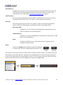
4.5 FIR FILTERING AND DESIGN
FIR filtering is a powerful and advanced feature of the OpenDRC-DA8. It allows construction of complex arbitrary
equaliztion and crossover filters with independent control of amplitude and phase. The parameters of each FIR
filter are set in the FIR settings window:
Browse
Opens a filter browser to select a file containing FIR filter coefficients. (See FIR filter file format
below).
Unload FIR
Deletes the currently loaded filter from the display and from the DSP memory.
Bypass
Disables the FIR filter. The filter is disabled when the button is "lit."
Send to DSP
Writes the currently loaded filter into the DSP memory.
File Mode / Manual Mode
In File Mode, the window displays the Browse and Unload FIR buttons as shown above. In
Manual Mode, the display changes to allow direct text entry of the FIR filter coefficients, as
shown below. The coefficients can be pasted into the window from a text editor.
miniDSP Ltd, Hong Kong / www.minidsp.com / Features and specifications subject to change without prior notice
30
4.5.1
FIR filtering overview
FIR ("finite impulse response") filtering differs from the IIR ("infinite impulse response") filters used in the PEQ
and crossover blocks. Technically speaking, IIR filters are recursive, meaning that each output value is partially
calculated from earlier output values as well as from input values. An FIR filter is specified by a large array of
numbers, whereas an IIR filter requires only a fairly small of values to be specified.
These numbers are conventionally referred to as "taps." The OpenDRC-DA8 can compute 9400 taps when run at
48 kHz, and 3400 taps when run at 96 kHz. These taps can be distributed as you wish across the eight output
channels, with the limitation that each output channel must have 6 or more taps and can have no more than
2048 taps. The decision on how many taps to allocate to each channel up to you, and should be determined
after working with an FIR filter design program (see below). The number of taps is set in the lower right corner
(click on the text entry box and type the desired number of taps, then press Tab or Return):
4.5.2
FIR filter design software
The filter coefficients must be created with the aid of filter design software. miniDSP does not provide any such
software, instead referring you to the many software packages available for this purpose (both freeware and
commercial). Please see the FIR filter tools page on our website.
4.5.3
Filter file format
The filter coefficient file loaded in File Mode uses IEEE 754 single-precision binary floating-point format. The
number of entries in the file must not exceed the allocated number of taps.
In Manual Mode, the coefficients must be plain text in this format:
b0
b1
b2
b3
b4
b5
=
=
=
=
=
=
1,
-1,
0.5,
-0.5,
0.2,
1,
miniDSP Ltd, Hong Kong / www.minidsp.com / Features and specifications subject to change without prior notice
31
4.5.4
Loading filter coefficients
In File Mode:
1.
Click Browse, navigate to the file containing the filter coefficients, and open it. A dialog will appear
confirming the number of coefficients loaded.
2.
Confirm that the response curve is as you expect.
3.
Press Send to DSP. This will write the coefficients into the DSP's memory.
4.
To clear the filter coefficients, click Unload FIR and then Send to DSP.
In Manual Mode:
1. Cut and paste the coefficients from the text output of the design program.
2. Press the Process button.
3.
Confirm that the frequency response graph is as you expect.
4.
Press Send to DSP. This will write the coefficients into the DSP's memory.
5.
To clear the filter coefficients, click Clear Taps and then Send to DSP.
If, after selecting a filter file or setting coefficients, the frequency
response graph does not change as expected, make sure that the
Bypass button is turned off.
If you clear the filter taps, make sure that you also bypass the
filter, otherwise there will be no audio through that channel.
miniDSP Ltd, Hong Kong / www.minidsp.com / Features and specifications subject to change without prior notice
32
4.6 WORKING WITH CONFIGURATIONS
The data that controls the audio processing is called a configuration. The processor stores four configuration
presets in its internal memory, which can then be selected from the front panel or via remote control.
4.6.1
Online and offline mode
Initially, the plugin is in offline mode. When the Connect&Synchronize button is used, the plugin downloads
configuration data into the processor and goes into online mode. Changes made in the plugin user interface
therefore fall into two categories:
The plugin is in online mode
The plugin user interface is “live” – that is, any changes made to the audio processing
parameters in the user interface are immediately downloaded to the processor. The effect of
these changes will thus be audible as the changes are made.
The plugin is in offline mode
Changes made to audio processing parameters in the plugin user interface will be made locally
only. The next time the plugin is synchronized to the processor, the parameters will be
downloaded to the processor (as long as the Synchronize Config button is selected).
The configuration contained in the miniDSP hardware unit cannot be uploaded back to the
computer. Therefore, you must save your configuration to a file if you wish to recover from any
changes you make while in offline mode.
4.6.2
Selecting a configuration
The active configuration is selected by one of the four buttons in the Configuration Selection area. By default,
configuration 1 is selected:
To switch to a different configuration, click on a different button. There are two cases:
The plugin is in online mode
Audio processing will switch to the parameters contained in the selected configuration. If,
however, parameters of the newly selected configuration have been changed since the last that
particular configuration was synchronized to the processor, then a dialog will appear asking you
if you want to synchronize the configuration.
The plugin is in offline mode
The user interface will update to show the parameters of the newly selected configuration. If
this configuration is changed in the user interface, it will be downloaded to the processor the
next time it is synchronized.
miniDSP Ltd, Hong Kong / www.minidsp.com / Features and specifications subject to change without prior notice
33
4.6.3
Saving and loading configurations
Configurations can be saved to and loaded from files. Each configuration is stored in a separate file. It is very
strongly recommended that each configuration programmed into the processor be saved to a file, to ensure that
the configuration is not lost if the processor is inadvertently reset.
To save the currently selected configuration to a file, drop down the File menu, then select Save and then Save
current configuration. In the file box, select a location and name of the file, and save it.
To load a configuration, first select the configuration preset that you wish to load into. Then drop down the File
menu, select Load, and then Load configuration to current slot.
If the plugin is in online mode, the new configuration data will be downloaded to the processor immediately. If
the plugin is in offline mode, the configuration will be loaded into the user interface only, and will be
downloaded to the processor the next time it is synchronized.
To copy a configuration from one preset to another, save the configuration to a file, then select
a different configuration preset and load the file.
4.6.4
Restoring to defaults
Configurations can be reset to the factory defaults from the Restore menu. There are two options:
Factory Default
Reset all four configuration presets to the factory default settings.
Current Configuration Only
Reset only the currently selected configuration preset to the factory default settings.
If the plugin is in online mode, the configuration data on the processor (all or just one configuration, as selected)
will also be reset to factory defaults. Otherwise, the reset will take place in the user interface only, and the new
configuration data will be downloaded to the processor next time it is synchronized.
miniDSP Ltd, Hong Kong / www.minidsp.com / Features and specifications subject to change without prior notice
34
4.7 KEYBOARD SHORTCUTS
The miniSHARC 4x8 plugin supports the use of the keyboard for many operations.
Tab
The Tab key moves the focus from the current user interface element to the next. A blue-grey
surrounding box usually indicates the user interface element with the focus. Shift-Tab moves the
focus in the opposite direction.
Up/down arrows
The up/down arrow keys (and in some cases, the left/right arrow keys) adjust the value of many
parameters, if they have the focus:
Output channel gain
Crossover frequency and filter type
PEQ filter frequency, gain, and Q
Space
The Space bar toggles buttons that have two states, such as Bypass, Invert, and Mute, if they
have the focus.
miniDSP Ltd, Hong Kong / www.minidsp.com / Features and specifications subject to change without prior notice
35
5 USING THE OPENDRC-DA8
Once configuration is complete, the computer is not required and can be disconnected. The front panel and/or
an infrared remote can be used to control:
Master volume
Master mute (remote control only)
Preset selection
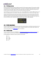
5.1 STATUS INDICATORS
The current status of the processor is indicated by a set of LEDs that indicates the currently selected
configuration preset (1 through 4).
5.2 FRONT PANEL CONTROLS
The processor uses a minimalistic physical control design with a single control knob.
To change the volume
Rotate the control knob clockwise to increase the volume, and counter-clockwise to decrease it.
If the computer is connected and the plugin is in online mode, the Master Volume display in the
plugin updates accordingly. (This is not necessary for normal operation, but can help with
troubleshooting if needed.)
To change the selected filter set
Briefly press the control knob. The Filter Set LED blinks quickly. Rotate the control knob until the
desired filter set LED is blinking. Press the control knob again, and the selected LED will remain
steady.
miniDSP Ltd, Hong Kong / www.minidsp.com / Features and specifications subject to change without prior notice
36
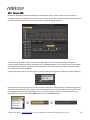
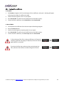
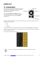
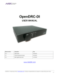
5.3 INFRARED REMOTE CONTROL
Many standard and programmable remote control units can
be used with the OpenDRC-DA8. By default, the OpenDRCDA8 recognizes the Apple Remote, with the key
assignments shown at right.
(The commands Config Inc and Config Dec change the
selected configuration preset up or down. For example, if
the currently selected preset is 1, pressing Config Inc
changes it to 2.)
In addition, the OpenDRC-DA8 can “learn” the control codes of your current remote if it supports one of the
following remote control codes:
NEC
Sony
Philips RC6
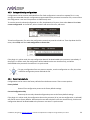
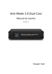
To initiate the learning process, drop down the IR Remote menu and select IR learning. Click on the Learn
button for an operation, and then press the desired button on the remote control. If the code is accepted, the
status will change to show a tick.
This screenshot shows the IR learning screen:
To "unlearn" a command, press the Learn button and wait for the plugin to time out.
miniDSP Ltd, Hong Kong / www.minidsp.com / Features and specifications subject to change without prior notice
37
6 ADDITIONAL INFORMATION
6.1 SPECIFICATIONS
Computer connectivity
Driverless USB 2.0 control interface for Windows and Mac OS X
Digital audio Input
S/PDIF on RCA connector / Isolated with digital audio transformer
A high quality onboard Asynchronous Sample Rate Converter ensures compatibility
with most sample rates, from 20−216kHz.
Analog audio outputs
8 x outputs on unbalanced (RCA) connectors, 2.0V RMS full scale output
Audio resolution
24-bit input and output, 48 kHz internal sample rate with the miniSHARC 4x8 plugin,
96 kHz internal sample rate with the miniSHARC 4x8 96k plugin.
Audio processing
32-bit floating-point processor
Storage/presets
All settings controllable in real time from software user interface.
Up to 4 presets stored in local flash memory.
Infrared remote
“Learning remote” capabilities (NEC, Philips, Sony)
Controls master volume, mute, digital input selection, preset selection.
Power supply
5 VDC single supply @ 600mA, 2.1 mm center-positive
Dimensions (H x W x D)
41.5 x 214.5 x 206 mm
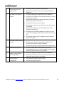
6.2 TROUBLESHOOTING
The following table lists the most common causes of issues. If following this table does not provide a solution,
see Obtaining Support below.
Item#
Symptoms
Troubleshooting recommendation
1
Cannot install software
a.
Confirm that you downloaded and installed the required
frameworks first (see Software Installation).
2
Software running in
background but not
showing
a.
The Adobe Air environment may need a network connection
the first time you run a plugin. Close the plugin program,
ensure that your computer has a network connection, and
restart the plugin.
b.
The Adobe Air environment may require a version update.
Download the latest version from http://get.adobe.com/air/.
miniDSP Ltd, Hong Kong / www.minidsp.com / Features and specifications subject to change without prior notice
38
3
4
5
Cannot connect to the
board by USB
a.
Reset the processor by power-cycling the unit.
b.
Make sure the processor is seen in the device manager as a
HID device.
No audio or low audio on
outputs
a.
Check the cabling from the processor to your amplifiers.
b.
Check that your amplifiers are turned on and that any volume
controls are turned up.
c.
Check that the input meters and output meters are showing
adequate signal (if not, see item 5).
d.
Check that master mute is not enabled.
e.
Check that the mute buttons in the output channel strips are
not enabled.
f.
Check that the FIR filters have valid coefficients (and are
bypassed if they do not).
g.
Check that your crossover frequencies are correct e.g. that
you don’t have high pass and low pass frequencies incorrectly
set.
h.
Check that the matrix mixer is sending the correct inputs to
the correct outputs.
a.
Check the cabling from your source.
b.
Check that your source is playing audio and that it is not
muted or have volume control turned down.
c.
Check that the plugin is synchronized with the hardware unit.
No signal showing on input
meters
6
Audio sounds distorted
a.
Check the output meter and ensure that you are not
overloading the outputs. If necessary, reduce the output gain
and/or the amount of boost in the EQ blocks.
6
Audio is coming through
the wrong outputs
a.
Check the cabling from the processor to your amplifiers.
b.
Check that you have correctly set up the matrix mixer to send
the correct inputs to the correct outputs.
Cannot reload a
configuration
a.
Confirm the file format of your file (.xml).
b.
Confirm the version of the file.
7
miniDSP Ltd, Hong Kong / www.minidsp.com / Features and specifications subject to change without prior notice
39
6.3 MCU FIRMWARE UPDATE
miniDSP may occasionally provide an update to the processor's MCU firmware to enable new features.
Currently, firmware upgrade is supported from the Windows platform only.
DO NOT DISCONNECT THE USB CABLE OR POWER FROM THE PROCESSOR WHILE FIRMWARE UPDATE
IS IN PROGRESS. DOING SO MAY “BRICK” YOUR PROCESSOR.
To update the MCU firmware:
1.
Download and install the latest miniSHARC 4x8 plugin from the User Downloads section of the miniDSP
website.
2.
Connect the processor to your computer via USB.
3.
Start the miniSHARC 4x8 plugin (if it is not already running).
4.
Click on the Connect&Synchronize button and select the Synchronize option from the dialog.
5.
From the menus, select Restore -> Upgrade Firmware. The processor will be put into boot loader mode
and the miniDSP upgrade utility will start. The status line should display “Device attached”.
6.
Click on the Open Hex File button and select the .hex file included in the download. It will have a name like
ENC_miniSHARC_ver2.17.hex.
7.
Click on the Program/Verify button. The status bar will indicate progress. Do not disconnect or power off
the processor during the firmware upgrade!
8.
After the status indicates that the verify has completed successfully, click on the Reset Device button, and
then quit the upgrade utility.
9.
Return to the miniSHARC 4x8 plugin. (If there is a dialog informing
"Connection to DSP closed," click on OK.) Click on the Connect button, and
then on About this product from the Help menu to verify the new
firmware version.
miniDSP Ltd, Hong Kong / www.minidsp.com / Features and specifications subject to change without prior notice
40
6.4 OBTAINING SUPPORT
1. Check the forums on miniDSP.com to see if this issue has already been raised and a solution provided.
2. Contact miniDSP via the support portal at minidsp.desk.com with:
a. The specific product you are having an issue with (in this case, OpenDRC-DA8).
b. A clear explanation of the symptoms you are seeing.
c. A description of troubleshooting steps (see Troubleshooting above) performed and your results.
miniDSP Ltd, Hong Kong / www.minidsp.com / Features and specifications subject to change without prior notice
41