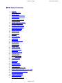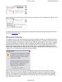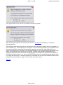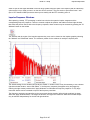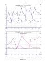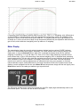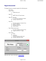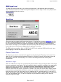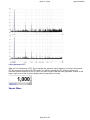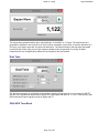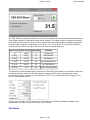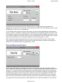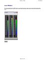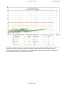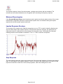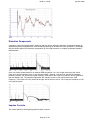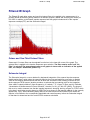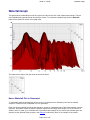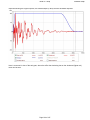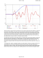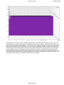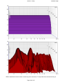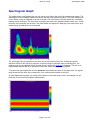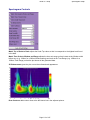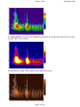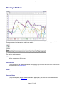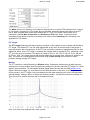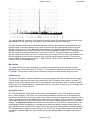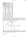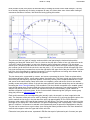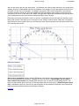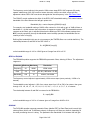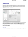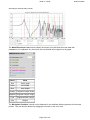
1
REW V5.1 Help
Copyright © 2004-2015 John Mulcahy All Rights Reserved
REW V5.1 Help
REW Help Contents
1.
2.
3.
4.
5.
6.
7.
8.
9.
10.
11.
12.
13.
14.
15.
16.
17.
18.
19.
20.
21.
22.
23.
24.
25.
26.
27.
28.
29.
30.
31.
32.
33.
34.
35.
36.
37.
38.
39.
40.
41.
42.
43.
Welcome
What's new in V5.1
Getting Started
Signals and Measurements
REW Overview
Calibrating the Soundcard
Checking Levels
Calibrating the SPL Reading
Making Measurements
Impedance Measurement
Thiele-Small Parameters
Measurements Panel
Impulse Responses
Minimum Phase
The limits of EQ
SPL Meter
Signal Generator
Level Meters
Graph Panel
SPL and Phase Graph
All SPL Graph
Distortion Graph
Impulse Graph
Filtered IR Graph
Group Delay Graph
RT60 Graph
Spectral Decay Graph
Waterfall Graph
Spectrogram Graph
Oscilloscope Graph
Overlays Window
RTA Window
EQ window
EQ Filters Panel
Equaliser Selection
Room Simulation
Importing Measurement Data
Communicating with AV32R DP or AV192R
Communicating with the BFD Pro
Soundcard Preferences
Mic/Meter Preferences
Comms Preferences
House Curve Preferences
Page 1 of 197
REW Help Contents
REW V5.1 Help
44.
45.
46.
47.
48.
49.
50.
51.
52.
53.
Analysis Preferences
Equaliser Preferences
View Preferences
Keyboard Shortcuts
File menu
Tools menu
Preferences menu
Graph menu
Help menu
SB Live! USB 24-Bit External Setup
REW homepage
Copyright © 2005 - 2015 John Mulcahy All Rights Reserved
Page 2 of 197
REW Help Contents
REW V5.1 Help
Welcome to REW
Welcome to REW
REW (Room EQ Wizard) is a Java application for measuring room responses and countering room modal
resonances. It includes tools for generating test signals; measuring SPL; measuring frequency and impulse
responses; generating phase, group delay and spectral decay plots, waterfalls and energy-time curves;
generating real time analyser (RTA) plots; calculating reverberation times; displaying equaliser responses
and automatically adjusting the settings of parametric equalisers to counter the effects of room modes and
adjust responses to match a target.
REW uses a logarithmically swept sine signal for its measurements. This is much faster than manual
measurements, more accurate, less likely to suffer from clipping at resonances, less sensitive to system
non-linearity than MLS and allows the impulse response of the room to be determined, which in turn is the
basis for many additional features. When using the Real Time Analyser displays REW can generate Pink
Periodic Noise sequences for much better visibility of low frequency behaviour than obtained using random
Pink Noise without the need for lengthy averaging.
For hints, tips and help visit www.hometheatershack.com/forums/rew-forum The REW home page is at
www.roomeqwizard.com
Requirements
REW can be used on Windows XP/7/8/8.1, OS X 10.7.3 or later and Linux
Minimum screen resolution: 1024 x 768
Minimum RAM: 1GB, 4GB or more recommended
For Windows and Linux REW requires V7 or later of the Java Runtime Environment, available
from http://www.java.com
On OS X a JRE is included within the REW app bundle for exclusive use of REW, Java does
not need to be installed
On Linux REW uses the Metal Look and Feel
RS232 serial communications (only used to communicate with TAG McLaren Audio AV32R DP
and AV192R AV Processors) only function on Windows.
Midi communication (used to set filters on Behringer BFD Pro DSP1124P and FBQ2496
equalisers) is supported on Windows. Linux may require Tritonus to support Midi comms. Mac
OS X should support Midi.
Diagnostics
REW saves diagnostic logs in the user's home directory, the location is displayed in the Help -> About
REW window. The logs contain information from the last 10 startups, including any error messages or
warnings that may have been generated.
The startup preferences for REW on Windows systems are stored in this registry key:
HKEY_CURRENT_USER\Software\JavaSoft\Prefs\room eq wizard
The preferences (under any OS) can be deleted by using the Delete Preferences and Shut Down option in
the Preferences menu.
No Warranty
THIS SOFTWARE IS PROVIDED "AS IS", WITHOUT WARRANTY OF ANY KIND, EXPRESS OR
IMPLIED, INCLUDING BUT NOT LIMITED TO THE WARRANTIES OF MERCHANTABILITY, FITNESS
Page 3 of 197
REW V5.1 Help
Welcome to REW
FOR A PARTICULAR PURPOSE AND NONINFRINGEMENT. IN NO EVENT SHALL THE AUTHOR BE
LIABLE FOR ANY CLAIM, DAMAGES OR OTHER LIABILITY, WHETHER IN AN ACTION OF CONTRACT,
TORT OR OTHERWISE, ARISING FROM, OUT OF OR IN CONNECTION WITH THE SOFTWARE OR
THE USE OR OTHER DEALINGS IN THE SOFTWARE
Acknowledgements
Soundcard debug data is generated by a modified version of Florian Bomers' ListMixers class, available
from the Java Sound Resources web pages at http://www.jsresources.org/
REW uses the JTransforms pure Java FFT library available at
http://sites.google.com/site/piotrwendykier/software/jtransforms
Thanks to Gerrit Grunwald for ideas and elements from his Steel Series components, available at
http://harmoniccode.blogspot.com
ASIO interfaces are supported using Martin Roth's JAsioHost, available at
https://github.com/mhroth/jasiohost
Copyright © 2004-2015 John Mulcahy All Rights Reserved
Get started with REW
Send feedback to [email protected]
Help Index
Page 4 of 197
REW V5.1 Help
What's New in V5.1
What's New in V5.1
REW now requires JRE7 or later on Windows
REW now requires OS X 10.7.3 or later. The OS X JRE is built in, Java does not need to be
installed.
Room Simulator
Graph that shows distortion with traces for THD and individual harmonics up to 10th
Support for ASIO drivers on Windows
Support for USB mics - MiniDSP UMIK-1, Omnimic, UMM-6 - with support for sensitivity
calibration data in the mic cal files
REW works at 44.1k and 48k sample rates on OS X
Support for ADA PEQ, miniDSP nanoAVR, miniDSP-96k,Emotiva UMC-200, Emotiva XMC-1,
waveFLEX DSP A8 and Xilica XP2040 equalisers
Target settings to specify a rise at low frequencies (a house curve) and a fall at high frequencies
Variable smoothing option, shortcut Ctrl+Shift+X
Peak trace on the RTA
Dual tone signals (SMPTE, DIN, CCIF and custom) in the generator for intermodulation
distortion measurements
Calculation of Intermodulation Distortion percentage on RTA when a dual tone signal is playing
CEA-2010 Tone Burst in the signal generator
A dark colour scheme can be selected
WAV, AIFF and PCM files can be dragged and dropped onto the REW main window to import
them
There is a control for a delay (up to 60 s) before the sweep starts
File import can now accept .csv files
Help Index
Page 5 of 197
REW V5.1 Help
Getting Started with REW
Getting Started with REW
REW is a software package that measures the transfer functions of acoustic systems and displays the corresponding frequency, phase
and impulse responses and various quantities derived from them. If that sentence made you ask yourself what on earth is he talking
about? It would be worth taking a few minutes to read through the introduction to Signals and Measurements, which explains the basic
concepts. Even if you are already familiar with the terminology a quick browse through that introduction may be helpful.
How REW makes its measurements
REW uses the logarithmic sine sweep measurement method. You can find out a great deal about the log sweep method, and the
various alternatives, by reading the paper "Transfer Function Measurement with Sweeps" by SWEN MÜLLER and PAULO MASSARANI,
but I'll give a basic explanation here. If you'd rather not know, you can skip the explanation.
To make a measurement we need a sound source (a loudspeaker or subwoofer) and a microphone (SPL meters
contain a microphone and many can be used instead of a mic). A logarithmic sweep signal is sent to the source,
which is a tone that starts at a low frequency and whose frequency increases steadily to a higher frequency. What
makes the sweep logarithmic is the rate at which the frequency changes, it takes a fixed time to double (for example,
the time for the sweep to go from 20 to 40Hz is the same as the time to go from 40 to 80Hz). The mic picks up the
sweep, hearing the sound that travels to it directly from the source but also the sound that gets to it by bouncing off
surfaces in the room first.
When we have captured the sound the mic picked up, the analysis starts. A process called "Fast Fourier Transform" (FFT) is used to
calculate the individual frequencies (their amplitudes and phases) that made up the sweep we sent to the source (its spectrum). The
same process calculates the amplitudes and phases of the frequencies in the signal the mic picked up. By comparing the amplitudes
and phases of the signals the mic saw with those the sweep contained we can work out how each frequency has been affected by the
room we are measuring. This is called the "Transfer Function" of the room from the location of the source to the location of the mic note that at a different source position or different mic position there will be a different transfer function, our measurement is only valid
for one specific source and mic position. Having worked out the transfer function we can use an "inverse FFT" to get from the frequency
amplitude and phase information to a time signal that describes the way any signal is changed when travelling from the source to the
mic. That time signal is called the "impulse response" - like the transfer function it is derived from, it is only valid for one specific source
and mic position.
The impulse response is actually exactly the same signal we would see if we could emit a very short but loud click at the
source position and record what the mic picks up afterwards ("very short" meaning lasting just the time of 1 sample at the
sample rate we are using for our analysis, so for a 48kHz sample rate that would be just 1/48,000 of a second which is
21 millionths of a second). You might ask why we don't just use a click then. One difficulty is that the click, because it is
so short, needs to be extremely loud for us to be able to pick up what happens after the initial click over the background
noise of the room. We could no longer use a speaker to generate that, we would need something like a starting pistol or
to pop a balloon. We would also need a mic that could cope with both the extremely loud click itself and the much quieter
echoes of the click produced by the room. You are likely to find that your family and neighbours are not that keen on you
repeatedly firing a pistol to figure out what your room is doing, and even if they put up with it your results would not be as
good as using a sweep. To be technical about it, you can achieve a much higher signal-to-noise (S/N) ratio by the sweep
method. The S/N is determined by the background noise level and by how much energy is in the test signal, which in
turn depends on how loud the signal is and how long it lasts. An impulse is extremely short, a few millionths of a second,
so to get any significant energy it needs to be very loud. A sweep can last for many seconds, so even at a modest
volume its total energy can approach as much as a million times more than an impulse.
Once the impulse response has been obtained, it can be analysed to calculate information about how the room behaves. The simplest
analysis is the FFT, to show the frequency response between the source and mic positions. However, we have some control over it.
Altering which part of the impulse response is analysed by the FFT changes what aspect of the room's response we see. The early part
of the impulse response corresponds to the direct sound from the source to the mic, the shortest path between them. Sound that has
bounced off the room's surfaces has to travel further to reach the mic, which takes longer, so the later parts of the impulse response
contain the contributions of the room. "Windowing" the impulse response to look at only the initial part shows us the frequency response
of the direct sound with little or no contribution from the room. A window that includes later parts of the response lets us see how the
room's contribution alters the frequency response. The ability to separate the contributions of the direct and later (reflected) sound is a
key difference between the frequency response derived from an impulse response and one we would get from an RTA, for example,
which can only show the total combined response of source and room.
Other information we can get from the impulse response include a "waterfall" plot, which is generated by moving a window in steps
along the response and plotting the various frequency responses in order to produce a 3D picture of the way the response changes over
time, and the room's "RT60" data, which is the time it takes sound in various frequency bands to decay by 60dB (meaning 1,000 times
smaller than it was).
Equipment Needed
Page 6 of 197
REW V5.1 Help
Getting Started with REW
The first requirement is a way to capture the test signal. There are a few options:
A USB microphone that comes with a calibration file. Such a mic can be used for low frequency or full range
measurements. If the cal file also has sensitivity data in a format REW recognises, it can also act as a calibrated
SPL meter. The MiniDSP UMIK-1 is recommended and has calibration data in an REW-friendly format, see
www.minidsp.com.
An alternative to a USB mic is an SPL meter with a line level analogue output. The Radio Shack meter is
perfectly adequate for low frequency room acoustics work, either the analogue or digital display version. The
Galaxy CM-140 meter has better tracking of the C-weight curve and better behaviour above subwoofer
frequencies than the RS meter, but is more expensive. Calibration files for the various models of the RS meter
and the CM-140 can be found in the Downloads area of the Equalization | Calibration forum at
www.hometheatershack.com/forums/
A final option is an analog microphone, but most mics will require a preamplifier to produce line level and to
supply the mic with phantom power. An SPL meter is still required to provide a reference SPL figure against
which to calibrate REW's SPL display. For full range measurements the mic must be calibrated for accurate
results.
A tripod to support the mic/meter. Small movements of the mic/meter can result in large variations in the measurements, for
repeatable results a means of supporting the mic/meter for a prolonged period is essential. For low frequency
measurements (below a few hundred Hz) the mic/meter can be set pointing straight up. This avoids having to move it to
measure different speakers and makes it easy to read the display on a meter. To make measurements at higher frequencies
it is best to point the mic/meter directly at the speaker being measured. In both cases the mic/meter should be placed at ear
height in your usual listening position.
If you are using a USB microphone your computer's headphone output can generate the test signals REW uses, no
soundcard needed. If you are using an SPL meter or a mic with a preamp then a soundcard (internal or external) with line
inputs and line or headphone outputs is required. Note that most PC and laptop mic inputs are NOT suitable and
should not be used (they have too much gain and most suffer from high noise levels and limited bandwidth) but
combination mic/line inputs can be used successfully. Inexpensive or built-in soundcards are typically adequate, a reference
measurement of a loopback connection can be used to remove the soundcard's frequency response from the measurement.
Check the REW forum at www.hometheatershack.com for examples of USB soundcards which have been found to work
well.
Cables to connect from your SPL meter or mic preamp's output to your soundcard (if you are not using a USB microphone)
and from the soundcard's line or headphone output to an input on your AV processor or equaliser. The leads need to be
long enough to reach from your computer to your listening position (where your mic/meter will be placed) and to your AV
processor or equaliser. If your soundcard has phono (RCA) connectors phono-phono leads will be needed, if the soundcard
has 3.5mm (1/8") sockets you will need a pair of stereo jack plug to stereo phono plug leads (also called Y adaptor cables,
Radio Shack part 42-2550) or stereo audio adaptors (Radio Shack part 274-883), see images below.
If you use Y adaptor cables you will also need two phono socket-to-phono socket adaptors (also called RCA phono plug
couplers, see image below) to connect to the leads that run to your SPL meter and AV processor (Radio Shack part 2741553).
If connecting to a BFD Pro DSP1124P or FBQ2496 you will need phono to mono 1/4" jack plug adaptors like that pictured
below (Radio Shack part 274-884).
Page 7 of 197
REW V5.1 Help
Getting Started with REW
An interface to your equaliser if using REW's RS232 or Midi communication capabilities to set up the equaliser's filters.
Requirements for communicating with TAG McLaren AV processors are detailed here, for BFD Pro DSP1124P or FBQ2496
(Midi interface) look here.
Connections
The overall setup for measuring when using an SPL meter is shown below. If you are using a USB microphone you do not need to
make any connections to the soundcard inputs, just connect the USB mic to a USB port on your computer.
When not using a USB mic, one of the soundcard's input channels is used to measure the sound pressure signal from your
mic/meter, it must be connected to the meter's or mic preamp's analogue output. The default is to use the Right input, but
either input can be used if you are not using a soundcard loopback connection (see below). A control in the Soundcard
Preferences tells REW which input to listen to.
Both of the soundcard output channels carry the test signal, one (typically the Right) must be connected to an input channel
on your AV processor or to the input of your equaliser. Connecting to your AV processor allows you to make measurements
that will show the response of main speakers as well as the subwoofer, and to view the integration between subwoofer and
main speakers. The effects of your AV processor's bass management can be included in the measurements. Connecting to
the left or right channel of an analog input will allow the corresponding main speaker and the subwoofer responses to be
measured - turn off or disconnect the main speaker or the sub to exclude them from a measurement.
The other input and output channels do not need to be used for basic measurement. The response of the soundcard itself
can be compensated for by taking a reference measurement with the output connected directly to the input and configuring
REW to subtract that measured response from subsequent room measurements. However, it is also possible to use a
loopback connection from the soundcard's left output to its left input as a timing reference for REW to automatically
compensate for the time delay in the soundcard and operating system when it makes a measurement. A timing reference is
required to make correct phase measurements, to compare time delays between measurements or for getting speaker delay
settings correct in multi-channel systems. If you wish to do this you may need an additional RCA phono plug coupler to
make the loopback connection. Whether REW uses one channel as a timing reference is controlled by a check box in the
Soundcard Preferences.
Page 8 of 197
REW V5.1 Help
Getting Started with REW
Equaliser Connections
If using an equaliser(such as BFD Pro DSP1124P or FBQ2496) to optimise your subwoofer's response, it should be connected between
your AV processor's LFE/Sub output and the subwoofer low level input. For a BFD Pro the operating level switches on the rear panel
should be pressed in to select the -10dBV range.
If the AV processor input being used has an anti-clipping feature (automatically reducing its sensitivity if it detects large signals) this
should be turned off, as it could shift the measurement levels. The sensitivity of the input should ideally be set to 0.5V, though this is not
critical.
The TAG McLaren AV32R DP and AV192R allow the test signal input to be routed to any speaker output via the Test Signal entry within
the TMREQ filter menus for each speaker, which is handy for measuring other speakers (see this note for details). They seem to be the
only AV processors with such a facility, other processor may have 5.1 or 7.1 analog inputs that can be used to similar effect, but in
some cases bass management will not be applied to such inputs, limiting the ability to check sub/main speaker integration.
SPL Meter Range
If you are using an SPL meter as the input the meter's range should be set to the value normally used for speaker level calibration and
must not be altered while using REW. If you are using the Radio Shack meter, select the 80dB range if you calibrate your system at
75dB (this is the standard level recommended by DolbyTM). Set your meter to C weighting and "slow".
If you are using a USB mic or a mic and preamp for measurement, you will need to select the Mic or Z Weighted SPL Meter option in
the Mic/Meter Preferences.
REW Overview
Having assembled the equipment required we can look it how REW itself is organised for making and analysing measurements in the
REW Overview.
Help Index
Page 9 of 197
REW V5.1 Help
Signals and Measurements
Signals and Measurements
"What does all this stuff mean anyway?"
To make sense of the measurements you can take with REW it is helpful to have an understanding of what
the measurements are. This topic gives an overview of the basics of signals and measurements and
explains how the various graphs in REW are generated and how they relate to what we have measured.
Signals, Sample Rate and Resolution
The first thing to understand is what a signal is, at least in the context of making acoustic measurements.
The signals we are interested in are sounds recorded through a microphone or SPL (Sound Pressure Level)
meter. The sound pressure generates electrical signals in the mic/meter which are captured by our
soundcard. The soundcard takes measurements of the electrical level at its input. Each measurement is
referred to as a sample. How often it takes its samples is controlled by the sample rate, REW supports
sample rates of 44.1kHz or 48kHz - which means the soundcard is capturing the level at its input either
44,100 or 48,000 times every second. Three seconds of a signal sampled at 48kHz means a sequence of
3*48,000 = 144,000 measurement values. The highest frequency that can be captured at any given sample
rate is half the rate - we need at least two samples for each cycle of the frequency to reproduce it. At 48kHz
sampling that means the highest frequency we can capture is 24kHz. Frequencies higher than half the
sample rate would cause aliasing, they would appear to be lower than they actually were. For example, a
25kHz signal sampled at 48kHz would actually look like a 23kHz signal. To prevent this, the inputs of the
soundcards have anti-aliasing filters that try to block signals higher than can be captured, but they are not
completely effective so we always need to consider the frequency content of the signals we are trying to
capture.
The resolution of the soundcard measurements is typically either 16 bits or 24 bits. 16 bit resolution is the
same as used on CDs, and is the resolution REW supports. Having 16 bit resolution means the individual
measurement values can range from -32768 to +32767 (numbers that can be represented with 15 binary
digits, plus a 16th binary digit to store the sign of the number). Rather than use the measurement numbers
directly, it is convenient to refer to them in terms of how close they are to the largest number, which is
referred to as Full Scale and abbreviated as FS. The full scale values are -32768 and +32767. The smallest
non-zero measurement value is 1, which as a percentage of full scale is 100*(1/32768) or approximately
0.003% FS. Anything smaller than that is seen by the soundcard as zero. The full scale value will
correspond to a certain voltage at the soundcard input - that is usually around 1 Volt. Soundcards that have
higher resolution, such as 24 bit, usually have the same maximum input voltage (around 1 Volt) but can use
a wider range of numbers to measure the voltage. For a 24-bit soundcard the full scale measurement values
are -8388608 and +8388607. That still is only 1 Volt (typically), the largest input voltage has not changed,
but the 24-bit soundcard has higher resolution - the smallest value it can detect is 100*(1/8388608) percent
of full scale, 0.000012% FS. It is with the very smallest signals that higher resolution has benefits. The full
scale value is often treated as corresponding to a value of one, and everything below full scale as being the
corresponding proportion of one, so half full scale would be 0.5 and so on.
Clipping
If the signal gets larger than the full scale value the soundcard is unable to follow it - the measurement
value cannot get higher than full scale no matter what is actually happening at the input. When the signal
has gone beyond the range the input can measure it is said to have been clipped. Clipping shows up in
input signals as flat parts of the response. If the clipping happens at the soundcard input it will be at +100%
FS or -100% FS and REW will warn you, but sometimes clipping can happen before the signal gets to the
soundcard (in a mic preamp whose gain is set too high, for example). In that case the measurement values
may never reach the soundcard's FS levels but the signal is clipped nonetheless. Clipping must be avoided
when measuring, because the captured signal no longer represents what was actually happening at the
Page 10 of 197
REW V5.1 Help
Signals and Measurements
input and that corrupts the measurement.
Viewing Signals
One way to look at signals is to plot the measurement values against time. When captured signals are
plotted in REW on the Scope graph they are shown as % FS, a signal that reaches 100% FS is the largest
the soundcard can capture. An example of an REW Scope plot is shown below, displaying a sweep signal
REW has generated and (in red) the resulting signal captured from a microphone.
We are usually interested in more than just the sample values. The frequencies that make up the signal
may also be of interest. The range of frequencies that make up a signal is called its Spectrum and we can
calculate them using a Fast Fourier Transform or FFT. The FFT works out the amplitudes and phases of a
set of cosine waves that, when added together, would give the same set of measurement values as the time
signal. The amplitudes and phases of those cosine waves are a different way of representing the time
signal, in terms of the frequencies that make it up rather than its individual measurement values. The
amplitudes are easy to understand, a larger amplitude means a bigger cosine wave. The phases indicate
the starting value for the cosine waves at the time of the first sample in the sequence that was measured. A
phase of zero degrees would mean the starting value was amplitude*cos(0) = amplitude. A phase of 90
degrees would mean a starting value of amplitude*cos(90) = 0. We are more often interested in the
amplitudes than the phases, but we shouldn't forget about the phases entirely - they contain half the
information about the shape of the original time signal.
When an FFT is used to calculate the spectrum it uses a set of frequencies that are evenly spaced from DC
(zero frequency) up to half the sample rate (the maximum that can be properly represented). The spacing
depends on the length of signal we analyse in the FFT. FFT calculations are most efficient when the signal
lengths are powers of two, such as 16k (16,384), 32k (32768) or 64k (65536). To calculate a 64k FFT from
a signal that is sampled at 48kHz we need 65536/48000 seconds of the signal, or 1.365s. The frequencies
would be spaced at 24000/65536 = 0.366Hz. If the FFT were generated from 16k samples the frequencies
would be 1.465Hz apart. The fewer samples used to generate the FFT, the further apart the frequencies are
so the lower the frequency resolution. For high frequency resolution we need to analyse long time periods of
signals.
RTA
A common way of viewing the spectrum of a time signal is to use a Real Time Analyser or RTA. The RTA
shows a plot of the amplitudes of the frequencies that make up the signals it is analysing. However,
whereas the FFT produces signals that are at uniformly spaced frequencies, an RTA groups them together
in fractions of an octave. An octave is a doubling of frequency, so the span from 100Hz to 200Hz is one
octave. So is the span from 1kHz to 2kHz - the actual frequency span of an octave fraction is more the
higher the frequency gets. For a 1/3 octave RTA the span is about 4.6Hz at 20Hz, but is 4.6kHz at 20kHz.
For a 1/24 octave RTA the spans are 1/8th as wide. Within the span of an octave fraction many individual
FFT values may be used to produce the single value the RTA assigns to that band of frequencies. Below is
an image of the REW RTA displaying the spectrum of a 1kHz tone and its distortion harmonics.
Page 11 of 197
REW V5.1 Help
Signals and Measurements
Systems and Transfer Functions
Viewing the spectrum of a signal has its uses, but we are also interested in how the equipment we use
alters the spectrum of signals. The way a system changes the spectrum of signals that pass through it is
called the system's Transfer Function. The transfer function has two components, the Frequency
Response and the Phase Response. The frequency response shows how the amplitudes of frequencies
are changed by the system, the phase response shows how the phases of frequencies are changed. A
complete description of the system needs both responses, very different systems can have the same
frequency response but their different phase response lets us distinguish them.
Note that it is important not to confuse a system's frequency response with the spectrum of the system's
output. The spectrum of a signal shows us what that signal is made up of in terms of the frequencies it
contains. The transfer function's frequency response tells us how the system changes the spectrum of
signals. The purpose of measurement software like REW is to measure transfer functions, and REW's SPL
& Phase graph shows the transfer function's frequency and phase responses. The frequency response
amplitude is shown as an SPL trace. Below is a plot of the frequency response (upper trace, left hand axis)
and phase response (lower trace, right hand axis) from a room measurement, showing the span up to
200Hz.
Page 12 of 197
REW V5.1 Help
Signals and Measurements
The Impulse Response
The transfer function shows us, through the frequency and phase responses, how the system affects the
spectrum of signals that pass through it. It characterises the system in what is called the frequency
domain. But what about the signal itself? How do we describe how the individual samples of the signal are
changed by the system, its time domain behaviour? The way a system changes the samples of a signal is
called its impulse response. The reason for the name will become clear. The impulse response (IR) is
itself a signal, consisting of a series of samples. Signals that are input to the system overlap the IR as they
pass through, sliding along it sample by sample. When the signal first appears, its first sample lines up with
the first sample of the impulse response. The system output for that first input sample is the first IR sample
value multiplied by the first signal sample value:
output[1] = input[1]*IR[1]
One sample interval later, the input has a 2 sample overlap with the IR. The output for this time period is the
2nd input sample times the first IR sample, plus the first input sample times the second IR sample:
output[2] = input[2]*IR[1] + input[1]*IR[2]
Another sample period later the input overlaps the IR by 3 samples, the output is
output[3] = input[3]*IR[1] + input[2]*IR[2] + input[1]*IR[3]
And so it goes on, as each successive input sample appears. That process of multiplying input signal
samples by IR samples is called convolution. Typically the impulse response has a fairly short duration,
much less than a second for a measurement of a piece of equipment and a second or two for a
measurement of a domestic-sized room, so eventually the output at each time period consists of the length
of the IR multiplied by the same length of the input signal, with all the individual products added up to give
the output for that time period.
So why call it "impulse response"?
What output would we get if the input signal consisted of a single sample at full scale, to which we will
assign a value of one, followed by zeroes for all other samples? The initial output sample would be
output[1] = input[1]*IR[1] = IR[1]
The next output sample would be
Page 13 of 197
REW V5.1 Help
Signals and Measurements
output[2] = input[2]*IR[1] + input[1]*IR[2] = 0*IR[1] + 1*IR[2] = IR[2]
The third sample would be
output[3] = input[3]*IR[1] + input[2]*IR[2] + input[1]*IR[3] = 0*IR[1] + 0*IR[2] + 1*IR[3] = IR[3]
and so on. The output would consist of each sample of the IR in turn. An input that has just a single full
scale sample followed by zeroes is called an impulse, so the output of the system when fed that input is
called the impulse response.
Relationship between Transfer Function and Impulse Response
As the transfer function and the impulse response are both descriptions of the same system we might
reasonably expect that they are related, and they are. The transfer function is the FFT of the impulse
response, and the impulse response is the inverse FFT of the transfer function. They are both views of the
same system, one in the frequency domain and the other in the time domain. The transfer function is simply
the spectrum of the impulse response.
Viewing the impulse response
The REW Impulse graph displays the impulse response. It shows the values as either % FS or dB FS. The
dB scale is useful to see a wider dynamic range of the signal, rather than plot the values directly it plots the
base 10 log of the values multiplied by 20. The top of the dB plot is 0dB FS, which corresponds to 100%
FS. A level of 50% FS would be 20*log(0.5) = -6dB FS. 10% FS is 20*log(0.1) = -20dB FS. The dB FS
scale is useful to see how the lowest levels of the impulse are behaving and where it gets lost below the
noise level of the measurement. The images below show an impulse response with % FS as the Y axis then
the same response using dB FS. In the second image we can see the impulse takes longer to decay into
the noise floor of the measurement than it might seem from the % FS plot.
Page 14 of 197
REW V5.1 Help
Signals and Measurements
Windowing the Impulse Response
The system we want to measure might be a piece of equipment, like a loudspeaker, but in acoustics the
system we are actually measuring includes other equipment and environments in the path between the
signal generated for the measurement and the signal picked up for analysis. These include amplifiers, the
microphone, the soundcard and most importantly the room itself. The system we are actually measuring
includes all those elements, so to focus on one part of it we will need ways of removing the influence of the
parts we are not interested in.
The response of the soundcard can be calibrated out by measuring it separately, as can the response of the
microphone. Removing the effect of the room is more difficult. It may be the effect of the room is what
interests us, especially if we are studying what we are hearing at our listening position, but if we are trying to
isolate the performance of a loudspeaker the room's contribution can obscure details of the loudspeaker's
performance.
The signal that reaches the microphone travels along a direct path, which is the shortest route from the
loudspeaker and so takes the shortest time. The sound from the loudspeaker also radiates outwards and
bounces off the room's surfaces. The reflections from those surfaces travel further before they reach the
microphone, so they take longer to arrive. If the signal was an impulse, we would expect to see the direct
arrival first, then the arrivals from the reflections. Those later arrivals are delayed by the extra time taken to
travel the additional distance. The shortest that extra time can be is the time it takes sound to travel to the
nearest surface - if that nearest surface was 3 feet away, for example, it would take at least 3 milliseconds
longer for a reflection from that surface to reach the mic than the direct sound from the speaker (in practice
it would take a little longer than that as the path distance would be a little more than 3 feet).
If we were to examine just the first few ms of the impulse response we would see the part that corresponds
to the initial arrival, which came directly from the loudspeaker without a contribution from the room. Looking
at a small portion of the impulse response in that way is called windowing the response (in the impulse
response images a few paragraphs above the blue trace shows the window). If we calculate an FFT for that
windowed portion of the IR we can see the transfer function for that direct arrival, which would be the
transfer function of the loudspeaker alone. There is a drawback, however. If we take the FFT of a short
signal, we can only see the response down to a limit that depends on how long the signal was. If we had a
whole second of signal we can get a frequency response that goes down to 1Hz. If we only had 1/10th of a
second, we only get a frequency response that goes down to 10Hz. In general, if the length of signal we
analyse is T seconds, the lowest frequency is 1/T - so if our window was only 3ms long, the frequency
response would only go down to 1/0.003 = 333Hz. To see low frequency responses free of room influences
the nearest surface needs to be as far away as possible. To adjust the window settings in REW click the IR
Windows button. By default REW uses window settings that include more than 0.5s of the impulse
response, so that the effect of the room can be seen.
Page 15 of 197
REW V5.1 Help
Signals and Measurements
Waterfalls
The SPL & Phase and Impulse graphs are the most useful for studying the transfer function we have
captured, but there is another graph that gives us useful information about what the room is doing to the
sounds we play in it. That graph is the Waterfall. The waterfall is a plot of how the spectrum of a section of
the impulse response changes as time progresses. It is produced by windowing an initial part of the
response, typically a few hundred ms when looking at room responses, and calculating an FFT of that
windowed section. The FFT produces the first slice of the waterfall. We then move the window along the
impulse response a little and calculate another FFT to produce the second slice of the waterfall. Moving the
window along a little further gives us the third slice, then the fourth and so on. As we move further along the
waterfall we start to lose the initial contribution from the loudspeaker and increasingly see just the
contribution of the room. The room's response is strongest at frequencies where there are modal
resonances, which are frequencies at which the sound bouncing back and forth between the room's
surfaces reinforces itself to produce stable, slowly decaying tones. Those frequencies stand out as ridges in
the waterfall plot, with the worst modal resonances having the highest ridges that take the longest to decay.
That was a very quick introduction to the basic signal and measurement concepts. If you have stuck with it
all the way to the end, well done. Now you have the information needed to better understand how REW
makes measurements.
Help Index
Copyright © 2010 John Mulcahy All Rights Reserved
Page 16 of 197
REW V5.1 Help
REW Overview
REW Overview
When REW is started it looks like this:
The main window is blank until we either make a measurement or load some existing measurements. The
SPL Meter, Signal Generator and Level Meters can be used without loading any measurements,
as can the RTA window, EQ window and the Room Simulator,
After making or loading some measurements the main window looks like this:
Page 17 of 197
REW V5.1 Help
REW Overview
The measurements appear on the left, in overlapping panels. The currently selected measurement has a
white background, the others are grey. On the right is the graph area for the current measurement.
All the toolbar buttons are now enabled. They are in 3 groups, firstly the buttons related to measurements:
These buttons allow a new measurement to be made, existing measurement files to be opened, all the
current measurements to be saved in a single measurement (.mdat) file, all the current measurements to be
removed, and an Info panel to be opened that shows additional information about the current measurement.
The next group has the various tools
The IR Windows button opens a window that allows the type and extent of the Impulse Response windows
for the current measurement to be changed. Next to that are the SPL Meter, Signal Generator and Level
Meters buttons. Then there is a button to open the Overlays graph window, which allows any or all of the
loaded measurements to be plotted on the same graph. The last three buttons are for the RTA window, the
EQ window (which is used to study the effects of EQ on the current measurement) and the Room
Simulator.
The final toolbar button brings up the Preferences panel
In the graph area there is a button to capture the current graph as an image
a selector strip to pick the graph type
and buttons to turn scrollbars for the graph area on/off, toggle the frequency axis between log and linear, set
Page 18 of 197
REW V5.1 Help
REW Overview
the graph limits and show the graph controls menu.
Below the graph is a legend area that shows the trace values at the cursor position
If smoothing has been applied the octave fraction (1/48 in the image above) appears between the trace
name and its value.
The first step in getting REW running is to set up the audio input and output and calibrate the soundcard.
Help Index
Page 19 of 197
REW V5.1 Help
Calibrating the Soundcard
Getting set up for measuring
When using REW to make measurements it is best to exit any other applications, disconnect from the
internet and disable any wireless networking. Interference on audio inputs from the wireless interface or high
processor demand from other applications, anti-virus updates and the like can cause gaps in the generated
or captured audio signals leading to incorrect measurement results.
The initial steps required to make room measurements are:
1.
2.
3.
4.
Choose the audio input and output
Calibrate the soundcard (not required when using a USB microphone)
Check levels
Calibrate the SPL reading (not required when using a USB microphone that has REWcompatible sensitivity cal data)
The various calibrations usually only need to be done once. If running REW for the first time it is best to
read through these initial help chapters in sequence rather than jumping directly to the individual setup
steps, however if your computer has already been set up using other acoustic measurement software you
may be able to skip directly to Making Measurements.
Choosing the Audio Input and Output
On Windows platforms REW can use either the Java soundcard drivers or ASIO drivers, on other platforms
only Java drivers are supported. If using the Java drivers REW defaults to using the audio input and output
which have been set as the defaults in your OS. If you wish to use other audio inputs or outputs, or use
ASIO drivers, or choose the specific devices, inputs and outputs to use (recommended) they can be
selected in the Soundcard Preferences panel, click the Preferences button in the toolbar to display the
panel. The device lists show all soundcards that REW has detected, when a soundcard has been selected
the input and output lists show the available inputs/outputs on that soundcard. ASIO devices appear in the
list if they have an installed driver even if the soundcard is not connected, connect the soundcard to
populate the list of supported sample rates. Note that if a USB soundcard is plugged in after REW has been
started it may take up to 1 minute for it to appear in the list of devices - this is a feature of the Java Runtime
Environment.
When using the Java drivers the lists may include both internal and external devices and default drivers
offered by the operating system.
Where possible, select the soundcard itself rather than the OS drivers "Primary Sound Capture Driver",
"Primary Sound Driver", "Java Sound Audio Engine" or similar. REW needs direct access to the controls on
the soundcard if it is to automatically adjust levels, this may not be possible if the OS drivers are selected.
Java Sound Audio Engine is also prone to pops and clicks during playback which degrade measurements.
Once the devices have been chosen, the input and output can be selected. When using Java drivers the
input will typically be called "LINE_IN" or "MICROPHONE" and the output will be "SPEAKER" or
"LINE_OUT", however these names may be different for USB soundcards - for example, the input may be
labelled "Digital Audio Interface". ASIO devices have more specific names for the available inputs and
outputs and each mono channel will be listed separately.
Page 20 of 197
REW V5.1 Help
Calibrating the Soundcard
Trouble-shooting tip: To prevent REW from accessing soundcard controls, leave the input and output
devices set to "Default Device". The actual input and output used and any level control settings will then
need to be made using the OS volume controls and/or the soundcard's mixer.
Sample Rate Selection
When using the ASIO drivers sample rates up to 192 kHz will be offered, if the soundcard supports them. It
is best to use 44.1kHz or 48kHz for acoustic measurements unless the test specifically requires
measurement results above 20 kHz (studying tweeter resonances, for example). Higher sample rates
increase memory use, slow down processing and do not improve accuracy.
Calibrating the Soundcard
This step is not required when using a USB microphone as the input, skip directly to Check levels
Once the audio input and output have been selected (or left as default if using the default OS settings)
REW is ready to make a calibration measurement of the soundcard's frequency response. This will be used
to remove the soundcard's response from room measurements and is an important check that the
soundcard is configured correctly.
1.
2.
3.
Connect the soundcard's line or headphone output directly to its line input - use the channel that
will be used to make measurements, which should be the same one that has been selected in
the Input Channel control.
Press the Calibrate... button on the Soundcard Preferences panel and follow the instructions in
the help panel at the bottom
The measurement result should be fairly flat (varying by much less than 1dB over most of the
range) but will roll off at the lowest and highest frequencies and will often have some ripple at
the high end. If the shows excessive variation between 20Hz and 20kHz a warning message will
be shown, the measurement should not be used. This is a valid measurement from a laptop's
internal card which rolls off fairly rapidly below 20Hz (graph vertical scale is 1dB/division):
This is a measurement from another laptop soundcard, showing better low frequency response
and a smoother high frequency response:
4.
Some results from the measurement are shown in the measurement notes:
Page 21 of 197
REW V5.1 Help
5.
6.
7.
Calibrating the Soundcard
If the measurement looks like this:
it is probably due to a feedback loop from the Line In to the output. This can happen if the
soundcard has some feature for record monitoring - for example, on the Soundblaster Live 24bit External there is a "Monitor" feature for the Line In that must be turned off to get correct
results, on some other Creative soundcards (e.g. Audigy 2 ZS) there is a Record Advanced
Controls setting for "Record without monitoring" that must be selected. It can also happen if
"Line In" is not muted in the Playback mixer for the soundcard.
Having obtained a measurement it needs to be saved as a calibration file. Press the Make Cal...
button in the Soundcard Preferences and choose a name and location for the file. The file is
saved and then automatically re-loaded as a calibration file to use for all subsequent
measurements. On the next startup the file will be loaded automatically with a confirmation
message like this one:
The calibration file will be applied to all new measurements made after it has been loaded. To
apply or remove a soundcard calibration file for an existing measurement, use the Change
Cal... button in the Show More part of the measurement panel.
Page 22 of 197
REW V5.1 Help
8.
Calibrating the Soundcard
To check that the calibration has been successful:
Leave the loopback connection from line output to line input in place
Uncheck the C Weighted SPL Meter box in the Mic/Meter Preferences and press
the Clear Cal button in the Mic/Meter Preferences to clear any mic/meter calibration
file that has been loaded. These steps are required because the loopback
connection has no C weighting or mic/meter response to compensate for
Press the Measure button
to bring up the Measurement panel
Click the expand button
if necessary to show the measurement settings and set
the End Freq to 20,000Hz
Press Start Measuring to make a measurement and check the result - it should be
flat to better than 0.1dB except perhaps below 10Hz, where there may still be slight
roll-off if the soundcard has poor low frequency range. The plot below has a vertical
scale of 0.1dB/division, the green line is the measurement result and the dashed
grey line is the soundcard calibration curve:
Page 23 of 197
REW V5.1 Help
Calibrating the Soundcard
If the C Weighted SPL Meter box has not been unchecked or the mic/meter
calibration data has not been cleared the measurement will show the U shape
of the inverse C weighting curve or the inverse of the mic/meter calibration
data:
Re-select C Weighted SPL Meter if using one and reload any mic/meter
calibration file that was cleared for the check
9.
Remove the loopback connection and connect the soundcard to the SPL meter and AV
processor/equaliser
Note that soundcard measurements made from the Soundcard Preferences panel use the full sweep range
to half the soundcard sample rate, regardless of the sweep end frequency setting, and the soundcard
calibration file is NOT applied to such soundcard measurements
Note also that the soundcard calibration file is only valid for the sample rate at which it was measured, if
the sample rate is changed the soundcard should be re-measured at the new sample rate
Setup information and example measurements for the Creative Soundblaster Live! 24-bit USB External
soundcard can be found here.
The next step is to Check levels
Help Index
Page 24 of 197
REW V5.1 Help
Check Levels
Check Levels
Setting the signal level REW uses during measurement involves generating a pink noise calibration signal
and adjusting the AV processor's volume control and/or the calibration signal level so that at the
measurement point (usually ear height at your main listening position) your SPL meter shows a level of
around 75dB. Then, if not using a USB microphone, the soundcard's input volume needs to be adjusted
to get a good signal level from the SPL meter or mic preamp when the cal signal is playing.
With a USB microphone the input volume control can be left at the unity gain setting, which is selected by
default when the microphone is first plugged in (and set automatically by REW if the Control input
mixer/volume box is ticked on the Soundcard preferences).
Check Levels Procedure
Open the Soundcard Preferences panel and choose whether to set the levels using your subwoofer or a
main speaker, making the appropriate selection in the drop-down box in the Levels panel. This tells REW
whether to use a subwoofer or speaker calibration signal. If you have connected the soundcard output
directly to your subwoofer or to an equaliser that is connected to your subwoofer then choose Use
Subwoofer to Check/Set Levels here, if you are connected to an AV processor input you can use the
subwoofer or main speaker settings.
Press the Check Levels... button and follow the instructions on screen. The test signal defaults to an RMS
Level of -12dB FS. If connected to an AV processor, start with the volume fairly low and increase it until the
meter is reading around 75dB. The exact level is not critical. If connecting directly to an equaliser such as
the BFD, use the Sweep Level control to change the level of the generated signal. In either case, the final
Sweep Level will be used for subsequent measurements - remember to use the same AV processor volume
setting whenever measurements are made.
If input levels are low DO NOT KEEP MAKING THE TEST SIGNAL LOUDER. Input levels should be set
through the volume controls on the input path, not the output, using very loud test signals is likely to
damage your speakers and your ears. Do not use test signal levels any higher than you would be
comfortable listening to for long periods.
Notes on Soundcard Volume Controls
The output volume control may have no effect on the level of line outputs, but will affect a headphone output
or the PC's speakers - if using a true line output for the measurement signal the output volume control
should be muted to prevent the signal being heard from the PC's own speaker(s).
The following notes are relevant if an output device and output have been selected in REW and the Control
output mixer/volume box is ticked.
REW sets the soundcard's wave volume to full scale and the output volume to half scale. On
exit REW restores the wave and volume levels that were in use when it started up if they are no
higher than the levels currently set (this is to reduce the possibility of creating a feedback loop).
The range of the REW controls is 0..1, but the underlying gain controls in the soundcard are
generally logarithmic. If you use REW to alter the volume control settings using the arrows on
the spinners, the settings will change in increments corresponding to 0.5dB, however the
soundcard's own controls will usually have lower resolution, so changes may have no effect on
the output until the next step in the soundcard's control is reached.
Changes in volume settings outside REW (e.g. in the Windows mixer) are automatically
detected and reflected in REW's controls.
In the playback mixer it is important to mute the input used for the signal from the mic or SPL
meter (usually Line In), otherwise a feedback loop results as the signal picked up by the
Page 25 of 197
REW V5.1 Help
Check Levels
mic/meter is fed directly back to the output. Here is an example of correct playback control
settings on a Windows system, only Wave is unmuted, the Wave volume is full scale and the
output volume is half scale.
Trouble-Shooting Setting Input Volume
Some soundcards do not provide an input volume control (e.g. some USB cards). If using an
SPL meter or mic and preamp, as long as the signal RMS level is within the -30 to -12 dB range
when the speaker/subwoofer cal signal is playing everything should work OK. If the level is
below -30dB try reducing the meter range to raise the level, but be careful not to reduce the
range to the point the meter is overloaded. If the level is above -12dB try increasing the meter
range to lower the level.
If using a USB mic the signal may be much lower, below -50 dB, this is OK.
Some soundcards do not provide programmatic access to their input volume control so REW
may not find a volume control or it may not be able to alter it. In that case you can use the
controls in the soundcard's mixer or the OS audio level controls to make the required
adjustments manually.
On some soundcards REW may not be able to directly select the required input via its device
and input selectors - for example, on Audigy 2 selecting the Line In is done by selecting "Analog
Mix" in the Record panel of the Basic tab of the Creative Surround Mixer then going to the
Source panel and muting all the sources except for Line In. If it does not seem possible to
select the required input via REW's device and input selectors, or REW does not seem to be
making the correct settings, leave the input device set to Default Device and make the input
selection and input volume adjustments via the soundcard's mixer or the OS audio level
controls. An example of suitable Windows volume control settings is shown below, with Line In
selected
Page 26 of 197
REW V5.1 Help
Check Levels
Setup information and example measurements for the Creative Soundblaster Live! 24-bit USB External
soundcard under XP can be found here.
After checking levels the next step is to calibrate the SPL reading.
Help Index
Page 27 of 197
REW V5.1 Help
Calibrating the SPL Reading
Calibrating the SPL Reading
Calibrating the SPL reading gives REW an absolute SPL reference by entering a reading from your SPL
meter while a speaker or subwoofer calibration signal is playing. Alternatively an SPL calibrator may be
used.
SPL Calibration Procedure
1.
2.
3.
4.
5.
Select the Mic/Meter tab of the Preferences panel
If using an SPL meter set it to C weighting and select the C Weighted SPL Meter box in the
Mic/Meter Preferences. Set the meter range to suit the measurement level used in the check
levels process (the 80dB range is recommended for the Radio Shack meter). If using a USB mic
or a mic and preamp select the Mic or Z Weighted SPL Meter option.
Open the REW SPL meter by clicking the SPL Meter button in the toolbar then press the
Calibrate button
On the dialog which appears choose whether to calibrate the meter reading using your
subwoofer or a main speaker driven by a calibration signal generated within REW, or to use an
external test signal you provide, making the appropriate selection in the drop-down box and
clicking OK.
Enter the reading from your external SPL meter (not the REW meter) in the calibration panel
and press Finished when done
For more information about the REW SPL Meter see the SPL Meter help
SPL Calibration Notes
At the end of the calibration process a message is displayed showing the maximum SPL that
can be measured with the current input level settings. If higher SPL needs to be measured the
input sensitivity must be reduced by lowering the soundcard input volume setting or, if using an
external microphone preamp, reducing the preamp gain.
A warning is shown if measurements are attempted before calibrating the SPL reading as the
results of the measurement would not reflect the actual SPL. The SPL reading is shown in red
until the SPL calibration procedure has been completed
REW remembers the calibration setting for the next startup, so it will usually not be necessary to
repeat this process, but check the REW SPL reading against your SPL meter or calibrator
before starting a new set of measurements
If the input volume setting is changed or another soundcard input is selected it will be necessary
to repeat the calibration process (selecting a different input or input device will cause REW to
treat the SPL reading as uncalibrated - the reading goes red).
Page 28 of 197
REW V5.1 Help
REW is now ready to make measurements.
Help Index
Page 29 of 197
Calibrating the SPL Reading
REW V5.1 Help
Making Measurements
Making Measurements
Once the audio input and output have been chosen, the soundcard has been calibrated, the levels have
been checked and the SPL reading has been calibrated REW is ready to make room response
measurements.
Connections should be as explained in Getting Started, if connected to an AV processor, select the input to
which the soundcard's output is connected.
Making a Measurement
Press the Measure button
(or Ctrl+M) to bring up the Measurement panel
REW can have 30 measurements loaded at once. If there are already 30 measurements when a
new measurement is requested a warning is given as the first measurement would need to be
removed to make room for the new one:
Make sure the SPL/Impedance selector at the top of the Measurement panel is set to SPL (see
Impedance Measurement for information about measuring impedance)
A delay of up to 60s can be selected before the measurement sweep starts, use the Sweep
Page 30 of 197
REW V5.1 Help
Making Measurements
Delay control to configure this
Click the expand button
if necessary to show the measurement settings
Set the Start Freq to the lowest frequency for which you wish to see the response and End Freq
to the highest. The sweep will span the range from half the start frequency to twice the end
frequency (with an overall limit of half the soundcard sample rate) to provide accurate
measurement over the selected range
Level controls the rms signal level at which the sweep is generated, relative to digital full scale.
The maximum value is -3 dB FS, which would place the peaks of the signal at digital full scale.
The default value is -12dB FS. This control is normally preset to the Sweep Level established
during the Check Levels process. If you will be comparing measurements from several
speakers, or comparing a series of measurements from a speaker, make sure they are
measured with the same Sweep Level
Length controls the duration of the sweep signal, specifying the number of samples in the
sweep sequence. The default is 256k. Dividing the number of samples by the soundcard's
sample rate gives the sweep duration in seconds. The overall duration includes silent periods
before and after the sweep
Longer sweeps provide higher signal-to-noise ratio (S/N) in the measurements, each doubling of
the sweep length improves S/N by almost 3 dB. However, the time required to perform the
processing after each sweep will more than double for each doubling of sweep length. If REW is
running on a computer which does not have a fast processor and a lot of memory,
measurements will be much faster using the shortest sweep length (128k samples), at a small
S/N penalty of about 3dB compared to the default. At least 2 GB of RAM and a fast processor
are recommended if using the 1M sweep, invalid measurements may occur on computers which
have insufficient RAM or processor speed
If Sweeps is more than 1 REW uses synchronous pre-averaging, capturing the selected number
of sweeps per measurement and averaging the results to reduce the effects of noise and
interference. The pre-averaging improves S/N by almost 3 dB for each doubling of the number
of sweeps. Averaging is particularly useful if the measurements are contaminated by
interference tones, whether electrical or acoustic, as they typically will not add coherently in the
averaging and hence will be suppressed by the process.
Note that some soundcards do not maintain sample synchronisation between the successive
sweeps which produces a corrupt measurement that has multiple, closely-spaced peaks of
approximately the same level in its impulse response, 1 peak for each sweep. This can also
happen if the input and output are on separate devices. If the frequency response with multiple
sweeps is significantly different from the response with a single sweep, stick with single sweeps.
In general it is recommended to use single, longer sweeps rather than multiple, shorter sweeps.
Total Time shows the overall duration of the sequence of sweeps
The Check Levels button generates a few seconds of a pink noise signal that spans the
frequency range selected for measurement and checks that the input level is not too high or too
low. Pressing Cancel while the pink noise signal is playing will turn it off (it turns off
automatically after 3 seconds). The rms level that was measured is shown on the measurement
panel, with a warning if the level is too high or too low
Page 31 of 197
REW V5.1 Help
Making Measurements
Press Start Measuring to make a measurement. If a delay has been configured time remaining
before the sweep begins is shown
When the sweep starts progress is shown on the measurement panel along with a display of the
measurement headroom
The result of the measurement is displayed in the graph area, information about the measurement appears
in the Measurements Panel. Measurements are given a default name of the date and time at which they are
made, a more appropriate name can be entered in the box at the top of the measurements panel
Page 32 of 197
REW V5.1 Help
Making Measurements
Notes relating to each measurement can be entered in the notes area, click the Notes button
area is not visible
if the notes
For details of the various ways of viewing the measured data, including averaging multiple measurements,
refer to the Graph Panel help.
Measurement Headroom
The headroom figure on the measurement panel shows how far away the input is from clipping, and hence
how much the sweep level could be increased before clipping would occur. The figure is red if there is less
than 6dB of headroom (warning that the input is close to clipping), green between 6 and 18 dB. A message
is shown if the headroom is more than 18 dB, as increasing the Sweep Level or the AV processor volume
would improve the signal-to-noise ratio in the measurement which in turn increases the accuracy of the
impulse and frequency responses. Note that after making such a change it will be necessary to use "Set
Target Level" to establish the new reference level for filter setting, and subsequent measurements will be at
a higher SPL on the graphs than those made before the change
If the room's resonances are very large the input signal level may exceed the input range and cause
clipping. If this occurs a warning is displayed, as input clipping will cause errors in the derived frequency
response. The sweep level or AV processor volume should be reduced and the measurement repeated.
Note that after making the change subsequent measurements will be at a lower SPL on the graphs than
those made before the change.
Page 33 of 197
REW V5.1 Help
Making Measurements
If the signal levels are very low this may indicate a connection problem:
After measuring the response of a channel you can look at adjusting EQ immediately, or make other
measurements first.
Note that some resonances which are very pronounced when measuring a speaker alone do not appear if a
pair of speakers (e.g. Left and Right) are run together - this is because the positioning of the speakers in the
room can prevent some resonances being excited (in particular, the odd order width modes will not be
excited by content which is the same on Left and Right speakers if they are symmetrically placed across the
width). Such resonances can often be left uncorrected, to identify them compare measurements from
individual channels with those made with two channels driven at the same time (achieved on AV32R DP or
AV192R by setting the Repeat Sig. entry in the TMREQ filter menu to Yes and selecting the channel which
is to repeat the test signal, or on other processors by connecting both left and right soundcard outputs to the
selected AV processor input or using a Y lead to drive two inputs at once).
Help Index
Page 34 of 197
REW V5.1 Help
Impedance Measurement
Impedance Measurement
REW can make measurements of impedance by using both inputs of the soundcard. Impedance
measurements of drive units can be used to calculate the Thiele-Small parameters. The general connection
arrangement for impedance measurements is shown below:
The sense resistor, which must be non-inductive, is used to measure the current flowing into the load,
which will be (Vleft - Vright)/Rsense. The voltage across the load is Vright, so the impedance is
voltage/current = Rsense*Vright/(Vleft - Vright). Note that the accuracy of the result is only as good as
the accuracy of the value entered for the sense resistor.
Good results can be obtained using a headphone output to drive the load, with a 100 ohm sense resistor. If
a line output is used the sense resistor typically needs to be much larger as line outputs have high output
impedance and limited drive capability, try 1 kOhm but note that the results will have much higher noise
levels.
An alternative is to drive the load via a power amplifier, which can deliver the lowest noise levels and most
accurate results, but great care must be taken as the levels a power amplifier can generate can easily
damage soundcard inputs. If using a power amplifier the sense resistor can be much lower, 33 ohms or
less, but the soundcard inputs should be connected via a resistive divider providing around 20dB of
attenuation and ideally the inputs should also be protected by back-to-back zener diodes to clamp the input
to less than 5V.
The soundcard input connected to the load must be the same one which has been chosen as the
input in the REW soundcard settings. In the diagram above that is the right input, but if the left is being
used simply swap left and right in the diagram. If the left and right connections are the wrong way around
your impedance measurements will show curves that are shifted up by approximately the value of the sense
resistor. It does not matter which headphone output is used as REW puts the test signal on both outputs.
Making an Impedance Measurement
Press the Measure button
the Impedance button
(or Ctrl+M) to bring up the Measurement panel and select
Page 35 of 197
REW V5.1 Help
Impedance Measurement
Enter the exact value of the sense resistor. This must be measured accurately with a good
quality, calibrated multimeter or impedance bridge, or a very high precision resistor (0.1%)
should be used. Any error in the value of the sense resistor directly affects the measurement
results.
Click the expand button
if necessary to show the measurement settings
Set the Start Freq to the lowest frequency for which you wish to see the response and End Freq
to the highest. If measuring a drive unit to determine its Thiele-Small parameters measure up to
20 kHz. The sweep will span the range from half the start frequency to twice the end frequency
(with an overall limit of half the soundcard sample rate) to provide accurate measurement over
the selected range.
Level controls the rms signal level at which the sweep is generated, relative to digital full scale.
The maximum value is -3 dB FS, which would place the peaks of the signal at digital full scale some soundcards may distort if -3 dB FS is used. For impedance measurements it is best to
use a high sweep level, e.g. -6 dB FS, but if you are using a power amplifier beware of
excessive levels.
Length controls the duration of the sweep signal, specifying the number of samples in the
sweep sequence. The default is 256k. Dividing the number of samples by the soundcard's
sample rate gives the sweep duration in seconds. The overall duration includes silent periods
before and after the sweep.
If Sweeps is more than 1 REW uses synchronous pre-averaging, capturing the selected number
of sweeps per measurement and averaging the results to reduce the effects of noise and
interference. The pre-averaging improves S/N by almost 3dB for each doubling of the number of
sweeps. Averaging is particularly useful if the measurements are contaminated by interference
tones, whether electrical or acoustic, as they typically will not add coherently in the averaging
and hence will be suppressed by the process.
Total Time shows the overall duration of the sequence of sweeps
The Check Levels button generates a few seconds of a pink noise signal that spans the
frequency range selected for measurement and checks that the input level is not too high or too
low. Pressing Cancel while the pink noise signal is playing will turn it off (it turns off
Page 36 of 197
REW V5.1 Help
Impedance Measurement
automatically after 3 seconds). The rms level that was measured is shown on the measurement
panel, with a warning if the level is too high or too low.
Press Start Measuring to make a measurement, progress is shown on the measurement panel
along with a display of the measurement headroom.
The result of the measurement is displayed in the graph area, information about the measurement appears
in the Measurements Panel. Measurements are given a default name of the date and time at which they are
made, a more appropriate name can be entered in the box at the top of the measurements panel.
When the mouse cursor is within the graph panel of the Impedance & Phase graph the equivalent series
resistance + inductance or resistance + capacitance and parallel resistance||inductance or
resistance||capacitance of the impedance at the cursor position is shown at the bottom left corner of the
graph, this is useful when making measurements of inductors or capacitors to check their value. For
capacitor measurements the values are most accurate at frequencies where the total impedance has
dropped below a few hundred ohms.
For details of the various ways of viewing the measured data, including averaging multiple measurements,
refer to the Graph Panel help.
Calibrating the Impedance Rig
Small gain differences between the soundcard input channels cause incorrect calculation of the load current
and the impedance. These can be calibrated out by making a measurement with the load disconnected and
the sense resistor shorted out. N.B. both soundcard inputs must be connected to the same output
signal.
Page 37 of 197
REW V5.1 Help
Impedance Measurement
Press the Measure button (or Ctrl+M) to bring up the Measurement panel, select the Impedance
button and set the sense resistor value to zero
Press Start Measuring to make a measurement. The completed measurement shows the level
of the measurement channel (usually right) compared to the reference channel, where a reading
of 100 Ohms corresponds to 100%, 99 Ohms would be 99% etc. If the difference between the 2
channels is too large (more than a couple of percent) the calibration is abandoned as it is likely
there is a connection error, re-check the connections and try again.
The calibration factor used for impedance measurements is shown in the measurement info panel next to
the measurement thumbnail, along with the sense resistor value.
Resistance of Test Leads
Page 38 of 197
REW V5.1 Help
Impedance Measurement
When measuring very low impedances the resistance of the test leads may become significant. To measure
this, first calibrate the rig as above, then make a measurement with the leads shorted together at the point
the load is attached (set the R LEADS value to zero before making the measurement). The measurement
should be fairly uniform, perhaps showing variation at very low frequencies depending on the low frequency
limitations of the headphone drive stage. If the result is more than one or two tenths of an ohm, check that
the connections are tight and the leads are not too flimsy. Enter the resistance from the flat part of the
measurement into the R LEADS box on the measurement panel.
Input Channels Swapped
If the input channels have been connected the wrong way around the impedance measurements will be too
high by approximately the value of the sense resistor, make a test measurement of a resistor (of less than
100 ohms) to check that everything is wired correctly.
Impedance Measurement Quality
The main source of measurement noise is acoustic noise and vibration during the measurement.
Loudspeakers act as microphones, generating small voltages in response to sounds and vibrations that are
picked up as part of the load voltage. To minimise this effect use high drive levels, low sense resistor
values, avoid noisy environments and isolate the loudspeaker from vibration. Using a power amplifier to
drive the speaker provides high signal levels and allows a low series resistor to be used.
Another source of error is the input impedance of the soundcard, which is in parallel with the load. This
limits the accuracy of the measurement of high load impedances, the method is most suitable for
impedances below a few hundred ohms.
Help Index
Page 39 of 197
REW V5.1 Help
Thiele Small Parameters
Thiele Small Parameters
The Thiele-Small Parameters window is used to calculate the parameters for a drive unit from
measurements of its impedance. To calculate all the parameters two measurements are required, one in
"free air" and a second with either mass added to the cone or with the unit in a sealed (air tight!) enclosure
(ideally with a volume a little less than the expected Vas). Note that the drive unit must be rigidly supported
during the measurements, and ideally mounted vertically (i.e. so that the cone is firing horizontally as it
would be in a typical loudspeaker installation). Some pre-conditioning of the unit with signals at medium
levels helps to stabilise the behaviour and suspension compliance and reduce memory effects in the
suspension from periods of storage or lack of use. Quiet conditions are important for good measurements,
drive units act as microphones and pick up noise and vibration, affecting the results. The measurements
should be made up to 20kHz so that the lossy inductance of the voice coil can be accurately modelled, and
the impedance calibration step should be carried out before making measurements.
An Example Run
To show the results of a TS parameter calculation a small bass-midrange drive unit was measured. It has
an effective cone area of 137cm 2. The plots below show the impedance measurements made in free air
and then with a mass of 5g added to the cone. REW determines whether the secondary measurement is
from a sealed box or added mass by looking at the resonant frequency, which is lower than free air for
added mass and higher for a sealed box. A least squares fit of an electrical model of the drive unit
impedance is carried out on the free air measurement to determine the model parameters. Another least
squares fit is carried out on the secondary measurement to determine the modified motional parameters and
Page 40 of 197
REW V5.1 Help
Thiele Small Parameters
the TS parameters are then calculated.
To calculate the TS parameters the two measurements are selected and the required values are entered:
the DC resistance of the voice coil (RDC ) in ohms. Accurate measurement of low resistances is
unfortunately not easy (see footnote), but the impedance model REW uses can easily
compensate for a DC resistance which is slightly lower than the actual, so it is recommended to
err on the low side
the effective area in square centimetres, most driver data sheets include an effective area figure
but if this is not available REW can calculate the figure for you given the effective diameter,
which is the diameter of the cone plus a proportion of the surround, typically 1/3 to 1/2, just click
the calculator icon on the left hand side of the effective area box
the air temperature in degrees Celsius
the air pressure in millibar
the volume of the sealed box in litres, or, if the second measurement was made with an added
mass, the additional mass in grammes
The Calculate Parameters button is then clicked, with the following results.
Page 41 of 197
REW V5.1 Help
Thiele Small Parameters
The first column of results in the bottom of the window show the loudspeaker resistance R E , which is
generally a little higher than the DC resistance; the minimum impedance Zmin after the peak and the
frequency fmin at which it occurs; f3, which is the frequency at which the impedance has increased to
sqrt(2)*Zf min ; the inductance at f3; the effective diameter and the effective area. The second column shows
the resonant frequency fS ; the mechanical (Q MS), electrical (Q ES ) and total (Q TS ) Q-factors and the F TS
figure (f S /QTS ). These parameters can also be calculated for any single measurement, without requiring a
secondary measurement to be selected. The LP figure and the MMS, C MS, R MS, V AS , Bl and Eta
(efficiency) figures in the third column can only be calculated using both measurements.
The "Compensate for leakage losses" and "Compensate for Air Load" check boxes are only applicable for
sealed box measurements, they take into account the leakage loss of the sealed box (which would be
shown as Ql at the bottom of the first column of results) and the air mass load due to the sealed box. These
Page 42 of 197
REW V5.1 Help
Thiele Small Parameters
compensations use the Carrion-Isbert method described by Claus Futtrup in the documentation for his
Driver Parameter Calculator application at http://www.cfuttrup.com/
The results can be copied to the clipboard by right-clicking on the results area, or written to a text file using
the Write Parameters to File button. When writing to file the separator between values, labels etc is as
defined in the File -> Export menu.
FDD Electrical Model
REW uses a driver impedance model that incorporates elements that cater for Frequency-Dependent
Damping. The model is described in detail in the paper by Thorborg, Tinggaard, Agerkvist & Futtrup,
"Frequency Dependence of Damping and Compliance in Loudspeaker Suspensions" J. Audio Eng. Soc., vol.
58, pp. 472-486 (June 2010). The diagram below shows the components of the model.
The model is split into two parts. The part at the right hand side models the motional impedance due to the
movement of the driver, with parameters R ES , C MES , LCES and Λ ES . This part reproduces the peak seen in
the impedance plot. It differs from the classical model by the addition of a frequency-dependent resistance
omega*Λ ES in parallel with LCES. Note that the FDD model R ES value is higher than that of the classical
model due to the effect of omega*Λ ES , which acts in parallel with R ES .
The other part of the model deals with the blocked electrical impedance of the driver. It is based on a model
developed by Thorborg and Unruh, described in “Electrical Equivalent Circuit Model for Dynamic MovingCoil Transducers Incorporating a Semi-Inductor,” J. Audio Eng. Soc., vol. 56, pp. 696–709 (Sept 2008). That
model begins with a drive unit resistance R E which is the DC resistance R DC followed by a small additional
resistance dR which models the resistance contribution due to eddy currents. It is followed by a series
inductance LEB and then a parallel combination of an inductance LE , a semi-inductance K E and a
resistance R SS . LE represents the inductance of the part of the voice coil located inside the motor gap. LEB
represents the part of the coil outside the motor gap. The semi-inductance K E has an impedance that
varies with the square root of omega*j. It models the effects of eddy currents and skin depth in the pole
piece. The parallel combination of LE and K E models the transition of the coil's behaviour from largely that
of a conventional inductor at low frequencies to a semi-inductor at high frequencies. The R SS component
models the effect of electrically conductive material in the magnet system, to be described in the paper by
Thorborg and Futtrup "Electrodynamic Transducer Model Incorporating Semi-Inductance and Means for
Shorting AC Magnetization", JAES Volume 59 Issue 9 pp. 612-627 (Sept 2011). The parameter values
REW determines may be modified if desired and the effect on the modelled impedance and phase traces
viewed on the graph, but the TS parameters which have been calculated will not be altered.
The plot below shows the modelled impedance traces (darker red and dashed) overlaying the measured
values.
Page 43 of 197
REW V5.1 Help
Thiele Small Parameters
When TS parameters have been calculated the derived and simulated motional and blocked impedance
magnitudes and phases can be plotted in addition to the total impedance traces. The simulated traces are
produced using the model parameter values, the derived traces are produced by subtracting the model
values from the measured values (for example, derived motional impedance is produced by subtracting the
modelled blocked impedance from the total measured impedance).
Simplified Model
As frequency-dependent component values are not supported by many circuit simulators REW also
calculates values for an alternative blocked impedance model using two parallel resistor-inductor pairs in
series, labelled R2-L2 and R3-L3, and the conventional R ES , C MES , LCES motional impedance model
without the frequency-dependent damping. The values of these components are shown in the "Simplified
Model" box. This diagram shows the simplified model components.
Page 44 of 197
REW V5.1 Help
Thiele Small Parameters
Measuring the driver DC resistance
Accurate measurement of low resistances is challenging, LCR meters that are in calibration may have a
suitable range and give good results. If you do not have access to a calibrated LCR meter an alternative is
to get an accurate measurement of a higher value resistor, perhaps 50 ohm or so, or purchase a very high
precision resistor (such as a Vishay bulk foil part) and form a voltage divider with a DC source, the
reference resistor and the driver. A decent multimeter can provide accurate voltage measurements,
measuring the voltage across the driver and the voltage across the reference resistor allows the driver
resistance to be determined from (ref resistor) * (driver voltage) / (ref resistor voltage).
Help Index
Page 45 of 197
REW V5.1 Help
Measurements Panel
Measurements Panel
The Measurements Panel shows the measurements which have been made or loaded and information
about them. The tabs on the panel are used to select individual measurements, they include a thumbnail of
the frequency response. The text next to the thumbnail shows the name of the file the measurement was
loaded from or has been saved to (if it has been saved), the date and time the measurement was made and
the mic/meter and soundcard calibration files that were used (hover the mouse over that text area to bring
up a tooltip that shows the full text width). The order of the measurements in the list can be changed by
clicking on the currently selected measurement and dragging it up or down to a new position in the list.
Collapse
The measurement panel can be made narrower to provide more screen area for the graph, click the
Collapse button to narrow the panel.
Page 46 of 197
REW V5.1 Help
Measurements Panel
Measurement Controls
The text box at the top of the measurement panel is used to change the name of the measurement. The
length of the name is limited to the width of the box. If a blank name is entered, "No Description" is used.
The name is shown in blue for new measurements or measurements with unsaved changes, otherwise it is
black.
The buttons in the column next to the name box are used to delete the measurement (deleting a
measurement removes it from REW, saved measurement files are not affected), save the measurement, set
the trace colour and expand or collapse the notes area. Trace colours can be reset to their defaults in the
View Preferences.
Notes relating to each measurement can be entered in the notes area, they are saved with the
measurement. Right-clicking in the notes area brings up a Cut/Copy/Paste menu.
Change Cal
The Change Cal button brings up a dialog to load, update or clear the calibration data files for the
Page 47 of 197
REW V5.1 Help
Measurements Panel
mic/meter or soundcard or to select whether a C-weighted SPL meter was used for the measurement. Note
that changing the calibration data or C-weighted setting will clear any waterfall, decay or spectrogram plots
that have been generated as they would no longer show valid data. Other affected plots will be regenerated
using the new cal data.
Help Index
Page 48 of 197
REW V5.1 Help
Impulse Responses
Impulse Responses
Interpreting impulse responses is an important part of acoustic analysis. An impulse response measurement can
tell us a great deal about a room and the way sound will be reproduced within it. It can show us what kinds of
treatment will be helpful and whether treatments have been correctly applied to achieve the best results. This
page explains impulse responses, the information that can be extracted from them and how REW can measure
and analyse such responses.
What is an impulse response?
Before we can get very far in interpreting an impulse response we need to understand what an impulse response
is. The impulse response is in essence a recording of what it would sound like in the room if you played an
extremely loud, extremely short click - something like the crack of a pistol shot. The reason for measuring the
impulse response (by more subtle means than firing a gun in the room) is that it completely characterises the
behaviour of the system consisting of the speaker(s) that were measured and the room they are in, at the point
where the measurement microphone is placed. An important property of an impulse, not intuitively obvious, is that
it if you break it up into individual sine waves you find that it contains all frequencies at the same amplitude.
Strange but true. This means that you can work out a system's frequency response by determining the frequency
components that make up its impulse response. REW does this by Fourier Transforming the impulse response,
which in essence breaks it up into its individual frequency components. The plot of the magnitude of each of those
frequency components is the system's frequency response.
When an impulse response is measured by means of a logarithmically swept sine wave, the room's linear
response is conveniently separated from its non-linear response. The portion of the response before the initial
peak at time=0 is actually due to the system's distortion - looking closely, there are scaled down, horizontally
compressed copies of the main impulse response there - each of those copies is due to a distortion harmonic, first
the 2nd harmonic, then the third, then the fourth etc. as time gets more negative. The initial peak and its
subsequent decay after time=0 is the system's response without the distortion.
In a perfect system of infinite bandwidth with totally absorbent boundaries, the impulse response would look like a
single spike at time 0 and nothing anywhere else - the closest you get to that is measuring the soundcard's
loopback response. In a real system, finite bandwidth spreads out the response (dramatically so when measuring a
subwoofer as its bandwidth is very limited). Reflections from the room's boundaries add to the initial response at
times that correspond to how much further they had to travel to reach the microphone - for example, if the
microphone were 10 feet from the speaker and a sound reflection from a wall had to travel 15 feet to reach the
microphone, that reflection would contribute a spike (smeared out depending on the nature of the reflection) about
5ms after the initial peak, because sound takes about 5ms to travel that extra 5 feet.
When measuring full range responses from loudspeakers (rather than subwoofer responses) the reflections are
Page 49 of 197
REW V5.1 Help
Impulse Responses
easier to spot as the higher bandwidth of the full range system keeps the spike of the impulse (and the reflections)
quite narrow, but you need to zoom in on the time axis to see them. They are easier to spot with a linear Y axis
(set to %FS instead of dBFS) and also show up more readily with the ETC smoothing set to 0.
Impulse Response Windows
After capturing a sweep, FFT processing is carried out to derive the system's impulse response and the
corresponding frequency response. There are controls to adjust the position and widths of left and right windows
that define the portion used to derive the frequency response, these controls may be accessed by pressing the "IR
Windows" button on the toolbar
The windows and the region of the impulse response they cover can be viewed on the Impulse graph by selecting
the "Window" and "Windowed" traces. The reference position for the windows is usually the impulse peak
The default settings for the windows will usually be suitable. In smaller rooms it may be necessary to use a shorter
right-side window duration, around 300-500ms - if the frequency response plot appears noisy and jagged try
reducing the right window period and hit "Apply Windows" to recalculate the frequency response. In very large
rooms the window can be increased to improve the frequency resolution.
The frequency resolution corresponding to the current total window duration (left and right combined) is shown
above the Apply Windows button - the longer the duration, the higher the resolution. Alternative window shapes
may be selected independently for the left and right windows.
Page 50 of 197
REW V5.1 Help
Impulse Responses
ETF users should note that ETF gate times are specified in a different manner to REW window durations, to
convert an ETF gate time to the approximately equivalent window width, multiply by 1.4.
Help Index
Page 51 of 197
REW V5.1 Help
Minimum Phase
Minimum Phase
In discussions of equalisation, and particularly equalisation applied to attempt to improve the acoustic response in a
room, "minimum phase" will often crop up - generally in the context of whether or not EQ can successfully be used
to address a response problem. So what is "minimum phase", and why should we care?
There are rigourous mathematical and systems theory definitions of what constitutes a minimum phase system, but
I will not repeat them here. In the context of acoustic measurements a system which is minimum phase has two
important properties: it has the lowest time delay for signals passing through it and it can be inverted.
Minimum Phase and Time delay
The "lowest time delay" property refers to the amount the frequency components of a signal are delayed while
delivering the measured frequency (SPL) response. We can see the delay characteristics directly in the Group
Delay plot of the system. Given a measured frequency response we cannot tell from the SPL response alone
whether what we measured has this "minimum delay" characteristic. If there was a time delay in the overall system
somewhere, such as the time taken for sound to travel from the loudspeaker to the microphone, that delay would
render the system non-minimum phase (in the strictest sense of the term) but would not alter the SPL response we
measured.
A time delay causes a phase shift that increases with frequency - for example, a delay of just 1ms results in a
phase shift of 36 degrees at 100Hz but 3,600 degrees at 10kHz, because 1ms is 1/10th of the 10ms period of a
100Hz signal but is 10 times the 0.1ms period of a 10kHz signal, and each period is 360 degrees. The phase shift
caused by a time delay is linear with frequency, meaning the 1ms example would give 36 degrees of phase shift at
100Hz, and twice that delay at twice the frequency or three times the delay at three times the frequency etc. If the
frequency axis is set to linear the phase plot of a time delay looks like a straight line droppping down as frequency
increases - how steeply it drops depends on how large the delay is.
Whilst constant time delays make it difficult to interpret the phase response, they can be removed from our
measurements and they do not cause any problems with applying EQ. However, just removing time delays (or their
effects) is not enough to make a system minimum phase, there is more to it than that.
Minimum Phase and Invertibility
Minimum phase systems can be inverted, which means that a filter can be designed that, if applied to the system,
would produce a flat response and correct the phase response at the same time. That is clearly a nice property to
find if we want to apply EQ. If we apply EQ to a system that is not minimum phase, or more particularly in a region
where it is not minimum phase, the EQ will not produce the results we would like. It may still be possible to achieve
a flat response, but correcting the phase response would elude us. It is simply not possible.
A simple example of something that renders a response non-minimum phase is reflections that are as large or
larger than the direct signal (reflections along paths that are different but the same length can combine to produce
higher levels, or a curved surface can focus a reflection). In the simple case of a reflection that is exactly the same
amplitude as the direct signal, we would find there were regularly spaced frequencies at which the reflection is 180
degrees out of phase with the direct sound. When those signals combine, the result is zero amplitude at those
frequencies (an extreme example of the comb filtering often seen in acoustic measurements). That zero level
cannot be restored to what it should have been by any amount of EQ, as the EQ affects the direct and reflected
signals equally so the signals still cancel. If a response has regions in it that are zero it cannot be inverted and it is
not minimum phase. If the reflection is larger than the direct sound the problem is equally tricky, as although we no
longer have a zero level we would end up with a situation where the corrections the EQ is applying would have to
keep getting larger to counter the ever larger reflection and we would quickly run out of headroom.
Identifying Minimum Phase Regions
Room responses are mixed phase, meaning there are some minimum phase regions and some regions that are not
minimum phase. The minimum phase regions tend to be at lower frequencies, but we cannot simply say a response
is minimum phase below some specific cutoff. It is not possible to identify minimum phase regions from looking at
Page 52 of 197
REW V5.1 Help
Minimum Phase
the wrapped phase response, especially if the measurement has any time delay. The unwrapped response gives
some more clues, plotted against a linear frequency axis, but often covers such a huge span that it is impractical to
use. Even if we remove any time delay in the measurement the phase response alone still doesn't let us easily
identify the minimum phase regions. There is a straightforward method, however. Here is a measurement of a
sub+main speaker in-room:
We might hazard a guess that this is largely minimum phase below the room's transition frequency, and nonminimum phase above, but to avoid the guesswork we can look at group delay. The group delay plot shows us how
much each frequency is being delayed - mathematically, it is the slope of the unwrapped phase plot, so anywhere
that phase is dropping linearly corresponds to a constant group delay region (i.e. that region is delayed by a
constant time). Here is the group delay plot for the measurement:
Page 53 of 197
REW V5.1 Help
Minimum Phase
That gets us a bit closer, we can speculate that the places where there are particularly wild swings in group delay
are not minimum phase, but it still doesn't let us easily identify the minimum phase regions. To do that, we need to
compare the measurement with a system that has the same amplitude response but is minimum phase and look at
the measurement's excess group delay. The minimum phase response is generated by using the measurement
amplitude and calculating the corresponding minimum phase from it, using a mathematical relationship between the
two that holds for minimum phase systems. By looking at the difference between the measured and minimum
phase (the excess phase) and measuring the slope of that difference to find the excess group delay, we get this
plot:
Page 54 of 197
REW V5.1 Help
Minimum Phase
Now we have something we can work with. Anywhere the excess group delay plot is flat is a minimum phase region
of the response. We can see there are regions even at very low frequencies where the response is not minimum
phase, between about 44 and 56Hz for example. These will usually correspond to regions where there are sharp
dips in the response, and underline the poor results which are often found when trying to lift such regions with EQ.
Low frequency peaks on the other hand are usually in minimum phase regions, the plot is fairly flat in the region of
the 28Hz and 60Hz peaks, which bodes well for attempts to apply EQ to them. In general, the peaks in a response
are a result of features that are correctible through equalisation (speaking technically, they are due to the poles of
the response and the equaliser can place zeroes that cancel the poles).
There are regions at relatively high frequencies which are minimum phase, such as 300 to 500Hz, despite the wild
variations of the response in that area, so it would be possible to apply EQ there. However, we need to remember
that the measurement is only valid for the microphone location at which it was made, and as frequency increases
the response changes more rapidly as the microphone moves. EQ that looks good at the original measurement
position may give worse results at other positions, so it is important to check wherever listeners will be. Narrow
bandwidth EQ adjustments should not be used outside the modal range, the higher the frequency the broader the
EQ adjustment needs to be to stand any chance of being useful outside a very small region.
As an aside, the excess group delay plot also clearly shows there is a time offset between the subwoofer and the
main speaker, the sub being about 25ms delayed, which is not so obvious from the overall group delay plot. Excess
group delay is a useful plot for time aligning speakers.
A common cause of non-minimum phase behaviour in rooms
If minimum phase systems are cascaded (connected in series) the overall system remains minimum phase - the
individual transfer functions of the systems are multiplied together and this retains the minimum phase
characteristics. In terms of the paragraph about invertibility above, the minimum phase systems will not have zero
amplitude anywhere and multiplying non-zero values together will not generate a zero value. However, adding the
responses of minimum phase systems gives a result which is typically not minimum phase throughout its response.
If there are any areas where the responses of the systems we are adding are equal in magnitude but opposite in
Page 55 of 197
REW V5.1 Help
Minimum Phase
phase, their sum will be zero. Here we see the problem for room responses, because the room response we
measure is the summation of many different responses due to the sound radiating into the room and reflecting from
its surfaces. This also applies even at the lowest frequencies, as we can see in the following.
Axial modes in a rectangular room
To provide a simple example of how the summation of the signals in a room can make it non-minimum phase, even
at low frequencies, we can look at the behaviour of axial modes in a perfectly rectangular room. Such results are
easily simulated (in this case by REW's own simple modal simulation tool), giving us a well controlled set of
responses to study. For the responses below the room dimensions are 7.00 x 6.86 x 3.43m, giving length modes
every 24.5Hz, width modes every 25Hz and height modes every 50Hz. The source is against the front wall, 0.25m
from the left wall and 0.15m from the floor. The mic is 1.5m from the rear wall, 4.28m from the left wall and 1m from
the floor. The room surfaces have uniform absorption of 0.20 at all frequencies.
The first plots show the individual SPL and phase responses of each axis. All are perfectly minimum phase, so the
excess phase (the black line) is flat and remains at zero. A linear frequency axis is used to more easily see the
modal effects, which are linearly distributed in frequency.
Page 56 of 197
REW V5.1 Help
Minimum Phase
Now for the combined response, which shows the minimum phase in grey and the excess in black, followed by the
Page 57 of 197
REW V5.1 Help
excess group delay plot:
Page 58 of 197
Minimum Phase
REW V5.1 Help
Minimum Phase
The response is no longer completely minimum phase anywhere in the span, as we can see from the excess
phase, but it deviates dramatically in the 70-120Hz region. At 110Hz, where there is a sharp dip in the response,
there is a sharp peak in the excess group delay. Attempting to EQ the response to flat in this region would be
foolish. Regions where the response is far from minimum phase would typically not give the results we might
expect and they are best left alone from an EQ perspective. Non-minimum phase regions are also likely to show
greater variation with position and to be more affected by changes within the room, as a change that affects any of
the signals that sum to the response in the minimum phase region can greatly alter the behaviour there. On the
plus side, broadband acoustic treatments in the room are effective regardless of the room's minimum or nonminimum phase behaviour.
Note that the predicted EQ results REW shows in its EQ window are obtained by applying the chosen filters to the
measured impulse response, and include the effects of non-minimum phase behaviour, so they accurately portray
the results that would be obtained at the point the measurement was taken.
Help Index
Copyright © 2010 John Mulcahy All Rights Reserved
Page 59 of 197
REW V5.1 Help
The Limits of EQ
Why Can't I Fix All my Acoustic Problems with EQ?
This topic deals with an important question: why isn't EQ enough to sort out acoustic problems? There are
plenty of products that claim to be able to correct room responses, so why would anyone need to bother with
acoustic treatments and bass traps and absorbers and all that stuff? Technology to the rescue, right?
Those are important questions, and understanding the answers to them can help a lot with better
understanding acoustics in general. There are a few places where the answer gets a little technical, but for
the most part the explanation is fairly easy to follow. Along the way to answering the questions above, we
will touch on the answers to two other questions:
Why does phase matter?
Why should I look at time domain signals instead of just frequency responses?
What does EQ do?
As a starting point we need to take a look at what an equaliser can do for us. The basic function of an
equaliser is to alter the frequency response. We can use it to try and make all the frequencies in the
response equal - the clue is definitely in the name there! Particular equalisers are sometimes described as
operating in the frequency domain, or operating in the time domain, or operating in both. In fact all
equalisers, without exception, operate in the time and frequency domains and have effects in both.
What are the limits of applying EQ?
Location, location, location
Before we start adjusting an EQ to alter the frequency response, we need to see a response to adjust, so
we need to make a measurement. This brings up the first limitation. The measurement is made at a single
position, and the frequency response of that measurement is only valid at that position, moving the mic
elsewhere and making another measurement will produce a different frequency response. It may be a little
different, or it may be (and usually is) a lot different. The changes made by an equaliser in the path to the
speaker are the same no matter where we are in the room, so since the response is changing in different
positions and the EQ isn't, it stands to reason that the EQ is only going to be good in places where the
frequency response is the same as the one we used when setting the EQ.
Reading some of the advertising blurb for EQ products you could be forgiven for thinking that some clever
guys somewhere have figured out a way around this. They haven't. The best you can do is to look at the
frequency responses measured at many positions in the area where you need the correction to work, figure
out which bits of them are sufficiently common, and come up with a compromise EQ setting that helps
somewhat in most places and doesn't do too much harm elsewhere. It can help, but it is no magic bullet.
What if I only listen in one spot?
So if the EQ is only good for one position, and I only sit in one position, what's the problem? The problem is
very small movements make big differences. At high frequencies the wavelength of sound is very short. At
20kHz it is just 17mm, about 5/8". The frequency response varies dramatically at high frequencies over very
short distances, so even if you only sit in one spot, and sit very still, the best you could hope for is an EQ
setting that would work up to a few kHz. For a more reasonable range of motion a few hundred Hz is more
likely.
Resolution
Page 60 of 197
REW V5.1 Help
The Limits of EQ
So we are prepared to make some compromises. One sweet spot will do, and fixing the response up to a
few hundred Hz would actually help a lot, it's usually all over the place down low. So let's break out the EQ
and start adjusting. The next problem we run into is the adjustments don't seem to be working right. Say the
frequency response shows a 6dB dip at 100Hz. We put in 6bB of boost there and tweak the width so it
matches the dip we saw. But the frequency response hardly moved, especially in the middle of the dip.
What's going on? The problem is probably with the resolution of the measurement. If you have used a 1/3
octave RTA, for example, to measure the response, the bar at 100Hz actually spans the range from about
89Hz to 112Hz. That 6dB dip is probably due to a much larger but very narrow dip within that 23Hz span.
You have to make a high resolution measurement to see what is going on, an RTA isn't going to cut it for
this work.
Headroom
The RTA has left the scene and we are making high resolution measurements. And they look awful. There
are big peaks and some huge, narrow dips. The 6dB dip we saw at 100Hz actually turns out to be a 17dB
dip at 98Hz. Never mind, the EQ allows up to 24dB gain. But listening with the fix in place reveals massive
distortion. We have run right out of headroom, with clipping all over the place. Even after playing around
with the levels to get rid of the clipping the result even slightly out of the sweet spot is much, much worse.
Sharp dips in the response are very sensitive to position, even at very low frequencies. The sensitivity to
position and the headroom problems mean we cannot do anything about them with EQ. The best we can do
is deal with the broad, shallow dips and work on the peaks.
Minimum phase and all that
We know most of the limitations of the equaliser now. We moved things around a bit and used a few
absorbers and got rid of the worst of the dips. After a lot of painstaking tweaking of the EQ the frequency
response is actually pretty flat. But it still sounds awful. So now what is going on?
The next few paragraphs get a little more technical, but it is worth sticking with it. Equalisers are, with a few
exceptions, minimum phase devices (some are linear phase, but that doesn't help with the problem facing
us). When we make an adjustment to the frequency response on the EQ, we also change the phase
response, an often ignored part of the measurement we made. We need to take a short diversion to look at
why we should care about the phase.
Why does phase matter?
Measurement software measures the Transfer Function of the system it is hooked up to. The transfer
function has two parts, the familiar frequency response, and the phase response. Systems can have the
same frequency response but actually have totally different effects on signals passed through them - the
difference lies in their phase responses. As a simple example of how big a difference phase can make,
consider the results from measuring two very different signals: an impulse and a period of periodic noise.
Both of these signals have perfectly flat frequency responses, looking at the frequency responses we could
not tell them apart. The time signals obviously look completely different, so what happened to that difference
when the signal went through an FFT to make the frequency response? It is all in the phase responses. The
impulse has zero phase at all frequencies. The periodic noise has random phase. Just as looking at
frequency response alone cannot tell us what a signal looks like, looking at the frequency response of a
transfer function alone cannot tell us what the system does to signals that pass through it, we have to look
at the phase response as well.
So the answer to why our system, with its nicely flattened frequency response, still doesn't sound right lies
in the phase response. Room responses are, for the most part, not minimum phase. The technical
explanation of that probably would not help with our understanding of the problem we are faced with, but the
outcome is this: we can do almost what we like with the frequency response (within the limits we have
discussed already) but the phase response is beyond the reach of our EQ. Anything we do in the EQ's
frequency response adjustments will have a corresponding effect in the phase response, and while the
frequency response adjustment we make can be equal and opposite to the room's frequency response, the
same is not true of the phase. That is what it means for the room not to be minimum phase, it has done
Page 61 of 197
REW V5.1 Help
The Limits of EQ
things to the phase of the signal that we cannot mirror in our EQ. Fixing the frequency response but not the
phase response means we cannot make the time signal look like it did before the room got hold of it,
however much time we spend fiddling with the EQ. We have hit the limit.
The value of looking at time signals
That brings us to another item I said we would touch on, the value of looking at time signals and not just at
frequency responses. The frequency response is only half of the description of what the system is doing to
signals that pass through it, the phase response is the other half. Trying to understand systems by looking
at the frequency response alone is like trying to understand a book by reading only the even numbered
pages. To really understand you need to look at both. That is a bit problematic, however. The frequency
response is fairly easy to understand, but the phase response doesn't give up its secrets quite so easily. To
properly use it we end up looking at various quantities derived from it, such as group delay or phase delay. It
gets complicated. But there is an alternative.
The systems we measure can be described in two ways: in the frequency domain by their transfer function
(frequency and phase responses) or in the time domain by their impulse response. They are two views of
the same system, the transfer function is the FFT of the impulse response and the impulse response is the
inverse FFT of the transfer function. To study how the system behaves and what it does to signals, we can
look at both. The impulse response has the benefit that it captures all the information in one signal, which
puts it one up on the transfer function, though it is not as immediately intuitive as a frequency response. It
readily gives up information that is less easily spotted in the transfer function though, such as early
reflections or the slow decays of room modes. It is well worth taking some time to become familiar with the
impulse response and some of the quantities derived from it, such as the impulse response envelope (aka
ETC).
Does EQ help or not?
Given all the limitations we have uncovered, and with the problem of non-minimum phase on top, we might
wonder whether the equaliser is any good to us. All is not lost, however. The non-minimum phase behaviour
of the room is connected to the dips in the response. It means we are even less able to deal with them, but
there wasn't a lot we could do about them anyway, so we are really not much worse off. On the plus side,
the peaks of the response are caused by features that lie firmly in the region our minimum phase equaliser
can handle. We can use the equaliser to help tame the peaks, and the lower down they occur, the better the
results we are likely to get - a nice complement to our acoustic treatments, since they start to struggle (or
we start to struggle with the size of them!) at low frequencies. EQ is a useful tool to keep handy when trying
to fix our acoustical problems, but it can only ever be a small part of the solution.
Help Index
Copyright © 2010 John Mulcahy All Rights Reserved
Page 62 of 197
REW V5.1 Help
SPL Meter
SPL Meter
The SPL Meter is an integrating, logging sound level meter that displays sound pressure level, equivalent
sound level or sound exposure level based on the RMS level of the input channel. It offers A, C and Z
weightings, fast or slow exponential filters, a high pass filter to suppress wind noise, and records minimum,
maximum and unweighted peak levels.
The meter takes into account both the soundcard and microphone calibration files and corrects its readings
accordingly, allowing IEC class 0 performance when used with a calibrated microphone and SPL calibrator.
Note that the maximum boost resulting from the calibration files can be limited by a setting in the Analysis
Preferences to prevent excessive boosting of the noise floor. Data recorded by the meter can be logged,
graphed and saved to a text file.
The meter displays either sound pressure level (SPL), time-average equivalent sound level (L eq ) or sound
exposure level (L E ) according to the selection made on the buttons below the display. The SPL reading is
filtered with either a "Fast" (125ms) or "Slow" (1s) time constant, selected via the F/S buttons. For general
use the "Slow" setting is best. When the HP button is pressed a high pass filter is applied that eliminates
content below approximately 8Hz.
Meter Weighting
SPL measurements use weighting curves to shape the signal they receive and emphasise those regions
that are of interest for certain requirements. The A and C-weighting curves are shown in the figure below.
Page 63 of 197
REW V5.1 Help
SPL Meter
C-weighting gives the broadest response (apart from the "Flat", "Zero" or "Z" weighting), with -3dB points at
31.5Hz and 8kHz. A-weighting has a much more pronounced low frequency roll-off. It is modelled on the
sensitivity of the ear to low level sounds (about 40dB SPL). A-weighting has the same high frequency rolloff shape as C, but the curves do not align at high frequencies because they are adjusted to both have zero
gain at 1kHz, which shifts the A-weighting curve up relative to C-weighting.
Meter Display
The meter display shows the currently selected measure, the level and an overload ("OVER") indicator
which is lit if the soundcard input range is exceeded. The OVER indicator can be reset by clicking in the
display area or using the Reset All button. When SPL is selected the display shows dB, the selected
weighting in brackets (A, C or Z) and either F for Fast or S for Slow. When measuring equivalent sound
level it shows LAeq, LCeq or LZeq according to the selected weighting. SEL is displayed when measuring
sound exposure level. The time over which the equivalent sound level or sound exposure level figures have
been calculated is shown in the Elapsed Time display at the bottom of the meter. Note that equivalent
sound level is useful for making measurements of subwoofer levels using your processor or receiver's
internal calibration signal, usually difficult due to the large fluctuations of the level. Equivalent sound level
displays a result averaged over the time since Reset All was last pressed; simply start the test signal, press
Reset All and wait for the reading to stabilise to get a precise level.
The SPL meter window can be resized as required, the main SPL display digits automatically scale to suit
the available space. The meter can also be set to full screen.
Page 64 of 197
REW V5.1 Help
SPL Meter
Below the main row of controls a level meter shows the current soundcard input level in dB FS, the peak is
shown by the red bar while the numeric indicator and the coloured bar show the rms level.
Below the soundcard level meter is a MinMax button to display min, max and peak values in the SPL
display and a Reset All button to reset the elapsed time, min, max and peak values, equivalent sound level,
sound exposure level and the overload indicator. The Calibrate button starts the meter calibration process,
whilst the record button turns the meter on or off. When MinMax is selected the values are displayed
alongside the main reading.
Meter Input Selection
The soundcard input channel which is measured is selected in the Soundcard Preferences. Setting the
audio input is described in Getting Started.
Calibrating the SPL Reading
Valid readings are not displayed until SPL Calibration has been carried out. The SPL reading may be
Page 65 of 197
REW V5.1 Help
SPL Meter
calibrated against an external SPL meter or SPL calibrator by pressing the Calibrate button. The text on the
button and the SPL meter digits are red if the meter has not been calibrated. If the soundcard input is
altered in the REW soundcard preferences, or if the input levels are altered, it will be necessary to recalibrate the SPL meter reading.
At the end of the calibration process a message is displayed showing the maximum SPL that can be
measured with the current input level settings. If higher SPL needs to be measured the input sensitivity must
be reduced by lowering the soundcard input volume setting or, if using an external microphone preamp,
reducing the preamp gain.
SPL Data Logging
The Logger button opens the SPL Logger graph window. The record button in the top right corner of the
SPL Logger graph starts or stops logging of SPL values. When logging is in progress the SPL meter on/off,
calibrate, weighting, filter time constant and high pass filter buttons are disabled. The logger records the
SPL (with the currently selected weighting and time constant), the minimum and maximum values, the
unweighted and uncalibrated peak value, the equivalent sound level and the sound exposure level. A Save
button above the SPL Logger graph allows the data recorded to be saved to a text file using the text
delimiter set in the REW File menu, log files can be loaded using the Open button.
Help Index
Page 66 of 197
REW V5.1 Help
Signal Generator
The Signal Generator can produce signals of the following types:
Sine Waves
Square Waves
Variable duty cycle
Dual Tone
SMPTE, DIN, CCIF and Custom
CEA-2010 Tone Burst
6.5 cycle Hann-windowed tone burst
Looping to repeat the burst
Pink Noise
Full range (spectrum to below 10 Hz)
Speaker Calibration
Subwoofer Calibration
Custom filtered
Pink & White Periodic Noise
Full range (spectrum to below 10 Hz)
Length to suit RTA FFT length
Sine Sweeps
Linear
Logarithmic
Changing frequency and/or level
Looping to repeat the sweep
Setting the audio output is described in Getting Started.
Page 67 of 197
Signal Generator
REW V5.1 Help
Signal Generator
RMS Signal Level
The RMS signal level can be set for any of the signal types with 0.1 dB resolution relative to digital full
scale. The arrow buttons on the RMS Level spinner change the value in steps of 1dB, or any required value
can be typed directly into the level box.
Sine Wave
Sine waves can be generated with frequencies between 10.0 and half the soundcard sample rate, e.g. 24
kHz for a soundcard operating at 48 kHz. The frequency is controlled by entering a value in the Frequency
box, or using the arrow buttons to increment or decrement the value in steps of 0.5 Hz for frequencies
below 200 Hz and steps of 1 Hz thereafter. The exact frequency that has been generated is shown at the
bottom right corner of the frequency display when the generator is running.
The RMS level can range from -90 to -3.0 dB FS (-3.0 dB FS is the maximum RMS level for a sine wave
before clipping, at this level the peaks are at 0 dB FS).
Frequency Tracks Cursor
The frequency can also be controlled via the graph cursor by checking the "Frequency tracks cursor" box.
When this box is checked the signal generator frequency is linked to the position of the graph cursor and
will change to follow the cursor frequency as it is moved - the changes are smooth with no phase
discontinuities.
Add dither to output
When the "Add dither to output" box is selected the generator adds 2 lsb pk-pk triangular dither to the output
to remove quantisation noise spikes. The level at which the dither is added is controlled by the sample width
selector to the right of the check box. N.B. When using the JavaSound drivers audio data is usually
limited to 16 bit precision. Dither is beneficial if making very precise distortion measurements of an
electronic device such as a receiver, processor or equaliser. It is usually not required when making acoustic
measurements as the quantisation artefacts it removes are far below the acoustic noise floor. The Graphs
below show the effect of the dither option during a loopback test of a soundcard playing a 1 kHz tone at -6
dB FS. The first plot is without dither, the second plot is with dither. Addition of dither cleans up much of the
noise that was apparent below -120 dB FS, especially at high frequencies, making the true harmonic
distortion levels more visible.
Page 68 of 197
REW V5.1 Help
Signal Generator
Lock frequency to FFT
When the "Lock frequency to FFT" box is checked the generator output frequency is locked to the nearest
FFT bin centre for the current RTA FFT length. This allows a rectangular FFT window to be used for
maximum spectral resolution of the RTA plot. The exact frequency that has been generated is shown at the
bottom right corner of the frequency display when the generator is running.
Square Wave
Page 69 of 197
REW V5.1 Help
Signal Generator
The square wave generator allows duty cycles between 1% and 99% in 1% steps. The frequency that is
generated is adjusted to ensure there is an even number of samples in the period, so that the spectrum of a
50% duty cycle square wave will only have odd harmonics. The actual frequency that has been generated
is shown at the bottom right corner of the frequency display when the generator is running, at higher
frequencies this can be significantly different to the frequency that was entered.
Dual Tone
The dual tone generator is to facilitate intermodulation distortion measurements. It has presets for SMPTE,
DIN and CCIF signals and allows custom signals to be generated with ratios of 1:1 or 4:1. Note that for valid
IMD results with custom signals f2 must be higher than f1.
CEA-2010 Tone Burst
Page 70 of 197
REW V5.1 Help
Signal Generator
The CEA-2010 Burst generator produces a 6.5 cycle, Hann-windowed tone burst at the selected frequency.
If the Repeat checkbox is selected the burst will be repeated. This signal is used for testing the maximum
power output of subwoofers by using an RTA to observe the levels of the distortion components produced
when the signal is playing, usually testing at 63, 50, 40, 31.5, 25 and 20 Hz. The limits for the distortion
components are shown in the table below, where f0 is the test signal frequency.
Start Freq (Hz) End Freq (Hz) Limit (dB)
Comment
16
1.59*f 0
0
Fundamental
1.59*f 0
2.52*f0
-10
2nd harmonic
2.52*f0
3.78*f5
-15
3rd harmonic
3.78*f 0
5.61*f0
-20
4th and 5th harmonic
5.61*f 0
8.50*f0
-30
6th - 8th harmonic
8.50*f 0
10 k
-40
Higher order harmonics
The highest level of the fundamental for which none of the limits are exceeded is the maximum output level
at that test frequency. When the CEA burst signal is playing the RTA shows the limits as an overlay,
provided the frequency of the burst is not more than 1,176 Hz. The recommended RTA settings for 44.1
kHz or 48 kHz sample rate are:
For 88.2 kHz or 96 kHz use FFT length of 131,072. Refer to the CEA-2010 standard for details of the
measurement procedure, or search for guides on the Internet.
Pink Noise
Page 71 of 197
REW V5.1 Help
Signal Generator
The Pink Noise generator uses white noise filtered through a -10 dB/decade filter generated from a
weighted sum of a series of first order filters, as devised by Paul Kellet circa 1999. Stated accuracy is within
0.05 dB above 9.2 Hz at 44.1 kHz sample rate.
The Full Range option outputs the filtered noise directly, giving the widest bandwidth and the greatest low
frequency content. The Speaker Calibration option applies 2nd order (40 dB/decade) filters at 500 Hz and 2
kHz, producing a signal with its energy centred on 1 kHz. Subwoofer Calibration applies filters at 30 Hz and
80 Hz. Both are broadly in line with the THX test signal recommendations. Custom Filtered allows low and/or
high cut filter frequencies to be set arbitrarily, subject to a minimum bandwidth of 1 octave.
REW automatically adjusts the signal levels for the various options and filter settings so that the RMS
values reflect the setting in RMS Level. Note that as Pink Noise has random variations some clipping of
peaks will occur at RMS levels above approximately -10 dB.
Pink and White Periodic Noise
Periodic Noise (PN) sequences are ideally suited for use with spectrum and real time analysers (RTA's).
They contain every frequency the analyser can resolve in a sequence length that matches the length of the
analyser's FFT. Their great benefit is that they produce the desired spectrum shape without requiring any
averaging or windowing, so the analyser display reacts much more rapidly to changes in the system than it
would if testing with Pink or White random noise, making them ideal for live adjustment of EQ filters. The
PN sequences REW generates are optimised to have a crest factor (ratio of peak level to rms level) that
does not exceed 6 dB. Use Pink PN when measuring with an RTA or White PN with a Spectrum analyser.
The Length control must be set the same as the length of the FFT used by the analyser. If it is set shorter
Page 72 of 197
REW V5.1 Help
Signal Generator
than the analyser FFT there will be notches in the analyser display, as the periodic noise will not contain
some of the frequencies the analyser is looking for. If it is set longer the extra frequencies will give a noisy
display requiring more averaging. The images below show the effect of correct and incorrect settings of the
PN length for a loopback measurement with 1/48 octave RTA that is using an FFT length of 65536 (64k).
Length 32768, shorter than FFT
Length 131072, longer than FFT (no averaging)
Length 65536, matching FFT
When using the REW RTA the PN length is automatically set the same as the FFT length.
The Save PN to WAV file button generates a 16-bit stereo wave file containing the PN sequence in both
channels. The file duration is approximately 1 minute, the level is per the RMS Level setting of the signal
generator. This file can be used to generate a test disc to be played on a system whose response is to be
measured. Make sure that the current soundcard sample rate corresponds with the format of the disc to be
made - for example, 44.1kHz should be used if generating a CD, or 48kHz for a DVD. When measuring the
system the sample rate and FFT length must be the same as used for the test disc.
Page 73 of 197
REW V5.1 Help
Signal Generator
Linear Sweep, Log Sweep
The Signal Generator can produce sweeps with configurable start frequency/ level, end frequency/level,
duration and linear or logarithmic progression. Sweep duration can be up to 60 seconds. If the "Loop" box is
checked the sweep will repeat continuously.
Measurement Sweep
The Measurement Sweep signal is used by REW when measuring system response. It consists of a
logarithmic sweep from the start frequency to the end frequency. The sweep duration is set using the
Length control. If the start frequency is below 20Hz the signal begins with a linear sweep from DC to 10Hz,
followed by a logarithmic sweep from there to the end frequency. This signal is selected automatically to
make sweep measurements.
Help Index
Page 74 of 197
REW V5.1 Help
Level Meters
Level Meters
The Level meters show the RMS level as a coloured bar and a numeric value at the bottom of the meter
and the peak value as a red line and a numeric value at the top of the meter. Levels are in dB below Full
Scale
Help Index
Page 75 of 197
REW V5.1 Help
Graph Panel
Graph Panel
The graph panel shows plots for the currently selected measurement. The plots are selected via the buttons
at the top of the graph area.
The various graph types are:
SPL and Phase
All SPL
Distortion
Impulse
Filtered IR
Group Delay
RT60
Spectral Decay
Waterfall
Spectrogram
OscilloScope
Options that affect the appearance of the traces can be found in the View Preferences.
Each trace can be turned on or off via the selection buttons to the left of the trace name in the legend panel.
Trace names are in the same colour as the trace itself, whilst the line style for the trace is shown between
the label and the trace's value at the current cursor position. If a trace has smoothing applied the octave
fraction is shown (1/12th octave in the example below).
Capture Graph Image Button
This button at the top left corner of the graph area allows the current graph view to be saved as an image. A
dialog pops up to set the desired width of the image (click default to set the image to be the same width as
the graph). If the "Include Title" box is checked the graph type will be shown at the top of the graph. If the
graph has data that can have smoothing applied to it the amount of smoothing (if any) will be shown at the
top of the graph, alongside the title (if selected). If the "Include Legend" box is checked the image includes
the graph legend. Text typed into the box that shows "Type any additional text here" will appear on the
graph image near the top of the graph, beneath the title and/or smoothing settings. The graph will be saved
as either JPEG or PNG according to the type selected.
Page 76 of 197
REW V5.1 Help
Graph Panel
Scrollbars Button
The Scrollbars button toggles scrollbars for the graph area on/off, hiding the scrollbars provides more room
for the graph. The setting is remembered for the next startup. If the scrollbars are off, the graph can still be
moved by holding down the right mouse button while in the graph area.
Frequency Axis Button
The Freq Axis button toggles the frequency axis between logarithmic and linear modes. This function is also
available via a command in the Graph menu and the associated shortcut keys.
Graph Limits Button
The Graph Limits button allows desired top, left, bottom and right graph limits to be defined. A dialog pops
up in which the values are entered, they are applied as they are entered or by clicking the Apply Settings
button.
Graph Controls Button
The Graph Controls button brings up a menu of control options for the currently selected graph type, if there
Page 77 of 197
REW V5.1 Help
Graph Panel
are any.
Horizontal Axis Zoom Buttons
The horizontal axis zoom buttons appear when the mouse pointer is inside the graph area, they zoom in or
out by a factor of approximately 2 centred around the cursor position.
Vertical Axis Zoom Buttons
The vertical axis zoom buttons appear when the mouse pointer is inside the graph area, they zoom in and
out on the Y axis.
Variable Zoom
REW provides a variable graphical zoom capability by either pressing and holding the middle mouse button,
or pressing the right button then, while the right button is held down, pressing and holding the left button
and dragging the pointer.
When variable zoom is active a cross is displayed, split into quadrants allowing horizontal and/or vertical
zooming in our out depending on the mouse position. The amount of zoom is governed by how far the
mouse pointer is dragged from the start position.
Zoom to Area
When the Ctrl key is pressed followed by the right mouse button a zoom box can be drawn by dragging the
mouse. Note that on a Mac it may be necessary to press both the Ctrl and fn keys, or to hold down Ctrl and
drag two fingers on the trackpad. Measurement cursors are shown on the outside of the box, to zoom to the
shaded area click within it. If the shaded area is too small to zoom in to a message will indicate which
dimension is too small for zooming and what the limit is to allow zoom.
Page 78 of 197
REW V5.1 Help
Graph Panel
Undo Zoom
To undo the last Variable Zoom or Zoom to Area, press Ctrl+Z or select the Undo Zoom entry in the Graph
menu. This will restore the graph axes to the settings they had when the right or middle mouse button was
last pressed. This Undo feature can be used even if you have not zoomed, just press the right mouse button
when the axis settings are to your preference then you can return to these settings (undoing any
subsequent movements or control changes) by pressing Ctrl+Z.
Help Index
Page 79 of 197
REW V5.1 Help
SPL and Phase Graph
SPL and Phase Graph
The SPL and Phase plot (or Impedance and Phase for an Impedance measurement) shows the frequency
(dB or Ohms) and phase (degrees) responses of the measurement. The frequency response is labelled with
the measurement name, the phase response uses a brighter shade of the measurement colour and the right
hand plot axis. Note that to have valid phase information it is necessary to remove any time delays from the
Impulse Response. A time delay causes a phase shift that increases with frequency - for example, a delay
of just 1ms results in a phase shift of 36 degrees at 100Hz but 3,600 degrees at 10kHz, because 1ms is
1/10th of the 10ms period of a 100Hz signal but is 10 times the 0.1ms period of a 10kHz signal, and each
period is 360 degrees. The time delay of a measurement can be adjusted by changing the zero position of
the time axis using the Impulse graph controls, or by using the Estimate IR Delay control described below.
In addition to the measured phase, the plot can show minimum and excess phase plots that result from
generating a minimum phase version of the response, described further below. The plot also shows any
mic/meter or soundcard calibration data for the measurement. The calibration data can be changed or
removed by selecting Change Cal... on the measurement panel.
Minimum Phase/Excess Phase
If the Generate Minimum Phase control has been used to produce a minimum phase version of the
response the minimum and excess phase traces are activated. They show the minimum phase response
and the difference between the measured phase and the minimum phase (the "excess"). For more about
minimum and excess phase and group delay see Minimum Phase.
Mic/Meter Cal
The Mic/Meter Cal trace shows the frequency response of the Mic calibration data for this measurement
(the calibration file to use for new measurements is specified in the Mic/Meter Preferences). If C Weighted
SPL Meter was selected this curve will show the effect of C weighting (outside the range of the calibration
data file, if there is one). The trace is not shown if there is no mic/meter calibration data. The trace is drawn
relative to the middle of the graph.
Soundcard Cal
The Soundcard Cal trace shows the measured frequency response of the soundcard relative to its level at
Page 80 of 197
REW V5.1 Help
SPL and Phase Graph
1kHz (if a calibration file has been loaded via the Soundcard Preferences). The trace is not shown if cal
data has not been loaded. The trace is drawn relative to the middle of the graph. Fractional octave
smoothing can be applied or removed via the Graph menu and its shortcut keys. The smoothing is applied
to the SPL, phase and Group Delay traces. This is mainly used for full range measurements, as reflections
can cause severe comb filtering which makes it difficult to see the underlying trend of the response.
Smoothing should rarely be used for low frequency measurements as it obscures the true shape of the
response. When smoothing has been applied an indicator appears in the trace legend.
SPL and Phase Controls
The control panel for the SPL and Phase graph has these controls:
If Show points when zoomed in is selected the individual points that make up the SPL and phase
responses are shown on the graph when the zoom level is high enough for them to be distinguished (which
may only be over part of the plot)
The phase trace normally wraps at +180/-180 degrees. This is because phase is cyclic over a 360 degree
range (+90 is the same phase as -270). The trace can, however, be displayed without wrapping which is
what the Unwrap Phase control does. A difficulty with unwrapped phase is knowing where the correct zero
phase is, another is being able to view parts of the trace where the unwrapped value has become very
large. The unwrapped phase is offset (by a multiple of 360 degrees) so that it is within the range -180..180
degrees at the cursor frequency. The +360 and -360 buttons will also shift the phase trace in 360 degree
steps.
Wrap Phase changes the phase trace back to a conventional wrapped view with vertical lines where the
trace crosses 180 or -180 degrees.
Generate Minimum Phase will produce a minimum phase version of the measurement using the current IR
window settings. The minimum phase trace then shows the lowest phase shift a system with the same
frequency response as the measurement could have, while the excess phase trace shows the difference
between the measured and minimum phase. Using this control also generates a minimum phase impulse
plot and minimum and excess group delay plots, which can be viewed on the respective graphs.
Note that the IR window settings are important as the minimum phase response is derived from the
frequency (magnitude) response of the measurement, which in turn is affected by the IR window settings. If
the window settings are subsequently changed Generate Minimum Phase should be used again to reflect
the new settings. Note also that the shape of the left side window (the window applied before the peak)
affects the minimum phase result, a rectangular window will produce a response with lower phase shift than,
for example, a Hanning window.
Page 81 of 197
REW V5.1 Help
SPL and Phase Graph
If the system being measured was inherently minimum phase (as most crossovers are, for example) the
minimum phase response is the same as removing any time delay from the measurement. Room
measurements are typically not minimum phase except in some regions, mainly at low frequencies. For
more about minimum and excess phase and group delay see Minimum Phase.
Estimate IR Delay calculates an estimate of the time delay in the measurement by comparing it with a
minimum phase version. The delay it calculates can be removed from the impulse response by pressing the
Shift IR button on the panel shown after the delay is calculated. Note that shifting the impulse response will
clear any spectrogram which had been generated as the plot would no longer be valid.
The Generate Minimum Phase and Estimate IR Delay controls also appear in the Impulse graph control
panel.
The trace offset value moves the graph position, but does not alter the data so the legend values do not
change. If the Add offset to data button is pressed the current offset value is transferred to the
measurement data and the legend readings will update accordingly.
Help Index
Page 82 of 197
REW V5.1 Help
All SPL Graph
All SPL Graph
The All SPL graph is an overlay graph that shows all measurements (SPL and/or Impedance) that have
been made. It allows an average to be generated of all selected traces or arithmetic operations to be carried
out on pairs of traces to generate a new trace.
Average The Responses calculates an average of the dB SPL values of those traces which are selected
when the button is pressed. Phase is not taken into account. The frequency range of the averaging result
covers the region where the traces used overlap, for example if one trace was measured to 200Hz, another
to 500Hz and a third to 1000Hz the average would range to 200Hz (to the lowest end frequency). New
measurements (those made after the last average was generated) show new next to the trace value, whilst
those included in the last average show avg.
All SPL Controls
The control panel for the All SPL graph has these controls:
The smoothing control allows the fractional octave smoothing setting for all the currently selected traces to
be changed.
The Measurement offsets control allows the chosen measurement to be offset either temporarily or (by
Page 83 of 197
REW V5.1 Help
All SPL Graph
using Add Offset to Data permanently.
If Show points when zoomed in is selected the individual points that make up the SPL and phase
responses are shown on the graph when the zoom level is high enough for them to be distinguished (which
may only be over part of the plot)
The Trace Arithmetic controls allow the chosen pair of traces to be added, subtracted, multiplied, divided,
coherently averaged or merged. If both the chosen traces have impulse responses, the result will also have
an impulse response, however the sample rates must be either the same or related by an integer. For
example, traces at 44.1kHz and 11.025kHz can be combined via an arithmetic operation, the result will have
the higher of the two rates. This allows operation on band limited measurements which may have been
decimated to a lower sample rate.
If the traces have incompatible sample rates, or either does not have an impulse response, the result will
not have an impulse response, but it may have both magnitude and phase data if both the traces it was
applied to had magnitude and phase data, otherwise the result will only have magnitude data.
The frequency span of the result of an arithmetic operation will be from the lowest start frequency to the
highest end frequency of the traces operated on. Outside their frequency range traces are treated as being
zero valued, with the exception of the divisor in a division operation which is treated as being unity outside
its range. If the measurements actually have significant levels outside the measurement range the zero
setting will generate oscillations in frequency and time domains, for best results use traces that span the full
frequency range.
Notes
For meaningful results measurements that have impulse responses or phase data should be
properly time aligned before they are combined. An exception is the Merge operation, for which
REW will automatically align both magnitude and phase at the merge frequency, adjusting the
trace B time delay as required for the phase match. The amounts of the adjustments are shown
in the notes of the newly generated measurement.
The current impulse response window settings are used for each trace, the result uses the
same window settings as trace A
The result is smoothed using whatever smoothing was being used for trace A
Help Index
Page 84 of 197
REW V5.1 Help
Distortion Graph
Distortion Graph
The Distortion graph shows the measurement, its harmonic distortion components up to the tenth harmonic and Total Harmonic
Distortion (THD). The plots are derived from analysis of the impulse response. Impulse responses measured using logarithmic
sweeps separate distortion from the linear part of the system response, the distortion components appear at negative times,
behind the main impulse. Analysing the frequency content of these components allows plots of distortion harmonics to be
generated.
The harmonic plots can only be generated for frequencies within the bandwidth of the measurement. For example, if a
measurement is made to 20 kHz, the second harmonic plot can only be generated to 10 kHz, as the 2nd harmonic of 10k Hz is
20 kHz. Similarly the third harmonic plot can only be generated to 6.67 kHz (20/3). When opening measurements made before
the Distortion graph was added to REW fewer harmonics may be available.
Total Harmonic Distortion is generated from the available harmonics up to the tenth. At higher frequencies the THD plot will
incorporate fewer harmonics, according to which are available.
The plots of the Fundamental (the linear part of the measurement) and the distortion harmonics do not include mic/meter or
soundcard calibration corrections. This is to avoid the effect of the corrections generating a misleading view of distortion
levels. For example, mic/meter and soundcard calibration corrections boost the lowest frequencies of measurements to counter
the roll-off of the mic/meter and soundcard interfaces, but adding those corrections to a distortion plot would make distortion
appear to rise at low frequencies, hence their omission.
The fundamental and harmonic plots are smoothed to 1/24 octave. This cannot be adjusted. The distortion data can be
exported to a text file using File -> Export -> Distortion data as text.
Distortion Controls
The control panel for the graph has these controls:
The Distortion Figures control selects the units that are used for the harmonic distortion levels displayed on the graph legend.
The choices are dB SPL, which shows the actual sound pressure level of each harmonic; dB Relative, which shows how many
dB the harmonic is below the fundamental at the cursor frequency; and Percent, which shows the harmonic level as a
percentage of the fundamental.
The Highest Harmonic control allows the higher harmonics to be hidden if they are not of interest. For example, if Highest
Harmonic were set to 3 only the second and third harmonic traces would appear on the graph and in the graph legend.
Distortion Examples
Here is a distortion plot generated from a loopback measurement of a soundcard, produced at a high sweep level (-4dB FS,
which resulted in 2 dB of headroom at the gain settings used). The readings in the legend are with the cursor at 1 kHz. Note
that this plot has a very large SPL range, 140 dB, to make the harmonics visible on the plot.
Page 85 of 197
REW V5.1 Help
Distortion Graph
The THD trace has been omitted, as it overlays the 2nd harmonic trace (in red) which is the dominant component, 0.07%. The
3rd harmonic (in orange) is much lower at around 0.01%, whilst the higher harmonics are largely within the noise floor.
This is the impulse response for that measurement, the distortion peaks are to the left of the main peak. The first peak to the
left is the 2nd harmonic, the next is the third harmonic and so on.
Page 86 of 197
REW V5.1 Help
Distortion Graph
The next plot is from a room measurement. The 2nd (red), 3rd (orange) and 4th (yellow) harmonic traces are shown, along with
the THD (black). Higher harmonics were within the noise floor. The measurement shows a sharp rise in 3rd harmonic distortion
at 94 Hz, and a dramatic rise in all distortion components from about 2 kHz upwards. Further measurements at differing signal
levels established that this distortion was being introduce by the SPL meter used for the measurement.
Page 87 of 197
REW V5.1 Help
Distortion Graph
This is the impulse response for the in-room measurement, the distortion peaks are clearly visible to the left of the main peak.
Help Index
Page 88 of 197
REW V5.1 Help
Impulse Graph
Impulse Graph
The Impulse graph shows the impulse response for the current measurement. It can also show the left and
right windows and the effect of the windows on the data that is used to calculate the frequency response; a
minimum phase impulse; the impulse response envelope (ETC) and the step response.
The Y axis used for the impulse response can be selected as % FS or dB FS (FS = Full Scale) via a control
in the top left corner which appears when the mouse cursor is inside the graph area. The dB Fs scale is
equivalent to a "log squared" view of the impulse.
Dashed vertical black lines show the extents of the impulse response windows, a dashed red line shows the
reference position. If the window settings are changed the region outside the new area is shown shaded
until the settings are applied. It is best to set the Y axis to dB to adjust the windows as it is then much
easier to see where the response has decayed into the noise.
After each measurement the left window width is automatically set up. For full range measurements (and
down to end frequencies of 1kHz) the width is 125ms, below that it increases to allow for pre-ringing effects
of using a limited sweep range. To change the window settings for a measurement click the IR Windows
button:
Page 89 of 197
REW V5.1 Help
Impulse Graph
The impulse response is that of the whole system, including the mic/meter and the soundcard. The
mic/meter and soundcard calibrations are only applied when calculating the frequency response.
Minimum Phase Impulse
If the Generate Minimum Phase control has been used to produce a minimum phase version of the current
measurement's magnitude response a minimum phase impulse trace is activated, showing the impulse
response the minimum phase system would have.
Impulse Response Envelope
The envelope of the impulse, also called the energy-time curve or ETC, is useful to identify reflections and
see the overall shape of the impulse response. The plot below shows the envelope, the spikes after the
initial peak are due to reflections from room surfaces, the first spike occurs 3.25ms after the initial peak
indicating that the sound travelled an additional 1.11m or 3.7 feet to reach the microphone.
Step Response
The step response shows the output which would result if the input signal jumped to a fixed level and stayed
there. It is the integral of the impulse response. If there is an offset in the measurement input chain the step
response will show an overall rise or fall as time progresses, rather than tending back to zero.
Page 90 of 197
REW V5.1 Help
Impulse Graph
Distortion Components
A property of the log sweep analysis method is that the various harmonic distortion components appear as
additional impulses at negative time, with decreasing spacing as the distortion order increases. For example,
this plot shows spikes from distortion components up to the 8th harmonic on a laptop soundcard loopback
measurement:
Here is a similar measurement for an external USB soundcard, it is a 44.1k card rather than 48k, which
limits us to the 6th harmonic in the 1s pre-impulse period - however, only the 2nd, 3rd and 5th harmonic
peaks are evident, the 4th harmonic peak is barely visible above the noise floor (which is about 10dB lower
than the laptop card). The extended lobes after the impulse are due to the card's much lower -3dB
frequency, 1.0Hz versus 22.1Hz (note that the right side of the time axis is 2.0s in this plot compared to 0.5s
in the previous plot):
Impulse Controls
The control panel for the Impulse graph has these controls:
Page 91 of 197
REW V5.1 Help
Impulse Graph
The impulse response may be plotted with or without normalisation to its peak value according to the setting
of the Plot Normalised control. When normalised plotting is selected the peak will be at 100% or 0dBFS.
If Show points when zoomed in is selected the individual points that make up the response are shown on
the graph when the zoom level is high enough for them to be distinguished.
The response may be plotted inverted according to the setting of the Invert Impulse control. Note that this
has no effect when the Y axis is set to dB FS. If the soundcard you are using inverts its inputs that can be
corrected using the Invert checkbox in the Soundcard Preferences Input Channel controls.
Generate Minimum Phase will produce a minimum phase version of the measurement using the current IR
window settings. The minimum phase impulse then shows the response of a system having the same
frequency response as the measurement but with the lowest phase shift such a system could have. This
control also activates minimum and excess phase and group delay traces on the SPL & Phase and GD
graphs respectively.
Note that the IR window settings are important as the minimum phase response is derived from the
frequency (magnitude) response of the measurement, which in turn is affected by the IR window settings. If
the window settings are subsequently changed Generate Minimum Phase should be used again to reflect
the new settings. Note also that the shape of the left side window (the window applied before the peak)
affects the minimum phase result, a rectangular window will produce a response with lower phase shift than,
for example, a Hanning window.
If the system being measured was inherently minimum phase (as most crossovers are, for example) the
minimum phase response is the same as removing any time delay from the measurement. Room
measurements are typically not minimum phase except in some regions, mainly at low frequencies. For
more about minimum and excess phase and group delay see Minimum Phase.
Estimate IR Delay calculates an estimate of the time delay in the measurement by comparing it with a
minimum phase version. The delay it calculates can be removed from the impulse response by pressing the
Shift IR button on the panel shown after the delay is calculated.
Page 92 of 197
REW V5.1 Help
Impulse Graph
The t=0 offset controls can be used to shift the zero time position by either a specified number of samples
or a specified time. These controls can be used to manually remove measurement time delays or determine
the correct delay to align measurements of different speakers or drive units. Note that shifting the impulse
response will clear any spectrogram which had been generated as the plot would no longer be valid. If a
loopback was used as a timing reference the System Delay figure (which can be viewed in the
measurement Info panel) is shifted by the same amount as the zero time.
The Scale FR Peak control re-scales the impulse response to achieve a desired maximum SPL figure in the
corresponding frequency response. This may be useful to rescale an imported impulse response.
ETC Smoothing is used to smooth the envelope (ETC) trace using a moving average filter of the duration
specified in the spinner.
Help Index
Page 93 of 197
REW V5.1 Help
Filtered IR Graph
Filtered IR Graph
The Filtered IR graph allow octave and one-third octave filters to be applied to the measurement. It is
primarily aimed at examining decay behaviour in different frequency bands and analysing the results per
ISO 3382. In addition to the filtered impulse response itself this graph includes traces of the impulse
response envelope (ETC) and the Schroeder integral.
Octave and One-Third Octave Filters
Octave and 1/3 octave filters can be selected from the box in the lower left corner of the graph. The
selected filter is applied to the Impulse Response upon selection. The filter remains active until "No
Filter" is selected. The measurement name on all graphs is shown with an indication of the applied
filter, for example "Auditorium [250Hz 1/3]".
Schroeder Integral
The Schroeder Integral is a curve obtained by backwards integration of the squared impulse response,
ideally starting from a point where the response falls into the noise and applying a correction (a starting
value for the integral) which assumes the rate at which the Schroeder curve is falling continues for the
whole response. REW uses an iterative procedure to estimate the best starting point for the integration,
often called "Lundeby's Method" (from the paper by A. Lundeby, T. E. Vigran, H. Bietz, and M. Vorländer,
“Uncertainties of Measurements in Room Acoustics,” Acustica, vol. 81, pp. 344–355 (1995)). The slope of
this curve is used to measure how fast the impulse response is decaying, deriving a figure for "RT60" which
is the time it would take sound to decay by 60dB. The curve shown on the Impulse graph is for the currently
applied filter, if any. When calculating decay data for the octave and one-third octave RT60 results the
impulse is first filtered to the corresponding bandwidth and centre frequency before the Schroeder Integral
for that band is determined and the various RT60 measures calculated.
Page 94 of 197
REW V5.1 Help
Filtered IR Graph
Filtered IR Controls
The control panel for the Filtered IR graph has these controls:
The impulse response may be plotted with or without normalisation to its peak value according to the setting
of the Plot Responses Normalised control. When normalised plotting is selected the peak will be at 100%
or 0dBFS.
The Time Reversed Filtering control applies the octave band filters backwards in time, this reduces the
filter's own contribution to the measured decay. When using 1/3 octave filters at low frequencies the filter
decay time can be significant, over 200ms for a 100Hz 1/3 filter, for example. Applying the filter in reverse
reduces this decay to less than 50ms, but it does affect the response somewhat, such that Early Decay
Time (EDT) figures using Time-Reversed filters may not be valid.
The Show Data Panel control shows a panel on the graph containing the results for the decay values. The
RT60 figures include the decay range over which they have been calculated and an "r" value, the
regression coefficient, which measures how well the data corresponds to a straight line. A value of -1 would
indicate a perfect fit, values lower in magnitude than -0.98 indicate the corresponding decay figure may not
be reliable. Unreliable figures are italicised and shown orange. The parameters available are:
EDT
Early Decay Time, based on the slope of the Schroeder curve between 0dB and -10dB.
T20
Decay time based on the slope of the Schroeder curve between -5dB and -25dB.
T30
Page 95 of 197
REW V5.1 Help
Filtered IR Graph
Decay time based on the slope of the Schroeder curve between -5dB and -35dB.
Topt
An "optimal" decay time based on the slope of the Schroeder curve over a variable range chosen to
yield the best linear fit. If the early decay time is much shorter than T30 the Topt measure uses a
start point based on the intersection of the EDT and T30 lines, otherwise it uses -5dB. REW tests
every end point in 1dB steps to the end of the Schroeder curve and chooses the one which gives the
best linear fit.
Curvature
(T30/T20 - 1) expressed as a percentage, providing an indication of how the slope of the decay curve
is changing. Values from 0 to 5% are typical, higher than 10% is suspicious and may indicate that the
room has a two-stage decay curve. If curvature is negative the results should be treated with caution
as they may be in error.
The graph can also show the "Regression Line", which is a line obtained by carrying out least squares linear
regression on the Schroeder curve over the range applicable to any particular decay parameter. The
selector for which regression line is to be shown is next to the Show Regression Line check box.
ETC Smoothing is used to smooth the envelope (ETC) trace using a moving average filter of the duration
specified in the spinner.
Help Index
Page 96 of 197
REW V5.1 Help
Group Delay Graph
Group Delay Graph
The group delay for the measurement is calculated from the slope of the phase trace. Note that if smoothing
has been applied to the measurement that will also smooth the phase and group delay traces. Smoothing
can be applied or removed via the Graph menu and its shortcut keys. Peaks and dips in the frequency
response will usually be accompanied by corresponding peaks and dips in the group delay. The group delay
will include any delay in the measurement due to time delays in the PC or soundcard, processing delays in
the equipment and delays due to the time sound takes to travel from source to microphone. Delays in the
PC or soundcard can be eliminated by using the Use Loopback as Timing Reference option in the Analysis
Preferences. If the group delay is tending towards a level at the upper end of the measurement that level
typically corresponds to the overall measurement delay.
Group Delay Controls
The control panel for the Group Delay graph has these controls:
Generate Minimum Phase will produce a minimum phase version of the measurement using the current IR
window settings. This activates minimum and excess group delay traces that show how the measurement's
group delay compares with the response of a system having the same frequency response but with the
lowest phase shift such a system could have. This control also activates minimum and excess phase and
minimum phase impulse traces on the SPL & Phase and Impulse graphs respectively.
Note that the IR window settings are important as the minimum phase response is derived from the
frequency (magnitude) response of the measurement, which in turn is affected by the IR window settings. If
the window settings are subsequently changed Generate Minimum Phase should be used again to reflect
the new settings. Note also that the shape of the left side window (the window applied before the peak)
affects the minimum phase result, a rectangular window will produce a response with lower phase shift than,
for example, a Hanning window.
If the system being measured was inherently minimum phase (as most crossovers are, for example) the
minimum phase response is the same as removing any time delay from the measurement. Room
measurements are typically not minimum phase except in some regions, mainly at low frequencies. For
more about minimum and excess phase and group delay see Minimum Phase.
Page 97 of 197
REW V5.1 Help
Group Delay Graph
If Show points when zoomed in is selected the individual points that make up the measured and minimum
phase responses are shown on the graph when the zoom level is high enough for them to be distinguished
(which may only be over part of the plot)
Help Index
Page 98 of 197
REW V5.1 Help
TR60 Graph
RT60 Graph
The RT60 Reverberation Time curves at each octave or one-third octave filter centre frequency are
displayed on this graph, with separate traces for the Early Decay time (EDT) and the 60dB decay times
T20, T30 and REW's Topt. See below for descriptions of each of these parameters.
RT60 Controls
The control panel for the RT60 graph has these controls:
The Time Reversed Filtering control applies the octave band filters backwards in time, this reduces the
filter's own contribution to the measured decay. When using 1/3 octave filters at low frequencies the filter
decay time can be significant, over 200ms for a 100Hz 1/3 filter, for example. Applying the filter in reverse
reduces this decay to less than 50ms, but it does affect the response somewhat, such that Early Decay
Time (EDT) figures using Time-Reversed filters may not be valid.
If the Show Correlation Factor box is checked the graph legend names shows the quality of the line fit for
the various decay measures. The "r" value shown after each decay measure is the regression coefficient,
which measures how well the data corresponds to a straight line. A value of -1 would indicate a perfect fit,
values lower in magnitude than -0.98 indicate the corresponding decay figure may not be reliable.
Unreliable values are italicised. The decay measures available are:
EDT
Early Decay Time, based on the slope of the Schroeder curve between 0dB and -10dB.
T20
Decay time based on the slope of the Schroeder curve between -5dB and -25dB.
Page 99 of 197
REW V5.1 Help
TR60 Graph
T30
Decay time based on the slope of the Schroeder curve between -5dB and -35dB.
Topt
An "optimal" decay time based on the slope of the Schroeder curve over a variable range chosen to
yield the best linear fit. If the early decay time is much shorter than T30 the Topt measure uses a
start point based on the intersection of the EDT and T30 lines, otherwise it uses -5dB. REW tests
every end point in 1dB steps to the end of the Schroeder curve and chooses the one which gives the
best linear fit. The range over which the value has been calculated is shown in the trace legend.
The RT60 plot can show horizontal bars centred on each filter frequency and spanning the filter's
bandwidth, or lines joining the filter centre frequencies, according to the Use Bars on RT60 Plot control
setting.
The reverberation times for the current measurement can be written to a text file using the File -> Export ->
RT60 data as text menu entry.
Help Index
Page 100 of 197
REW V5.1 Help
Spectral Decay Graph
Spectral Decay Graph
This graph shows spectral decay traces over the region from 10Hz to the end of the measurement sweep.
The plot used logarithmically spaced data at 96 points per octave with 1/48th octave smoothing applied.
The Spectral Decay plots are generated by shifting the impulse response window to the right by the slice
interval to generate each succeeding slice. Two windows are used, a left side window to taper the data prior
to the start of the region being analysed and a right side window that spans the selected window width. The
default window type for the left side is Hann, for the right side it is Tukey 0.25, other types may be selected
via the Spectral Decay entries in the Analysis Preferences. The initial reference point for the windows (end
of left window/start of right window) is the peak of the impulse response.
To produce the Decay plot click the Generate button in the bottom left corner of the graph area.
Decay Controls
The traces for each slice can be drawn as conventional lines or as filled areas, selected by the Fill slices
check box. The alternative views are shown below.
Page 101 of 197
REW V5.1 Help
Spectral Decay Graph
The time separation of the slices is controlled by the Slice Interval setting, the width of the impulse
response section that is used to generate the slice is set by the Window control. The corresponding
frequency resolution is shown at the bottom of the controls panel.
The control settings are remembered for the next time REW runs. The Apply Default Settings button
restores the controls to their default values.
Help Index
Page 102 of 197
REW V5.1 Help
Waterfall Graph
Waterfall Graph
This graph shows a waterfall plot over the region from 10Hz to the end of the measurement sweep. The plot
uses logarithmically spaced data at 96 points per octave. To produce the waterfall plot click the Generate
button in the bottom left corner of the graph area.
The labels at the sides of the plot show the time axis values
How a Waterfall Plot is Generated
To understand what the waterfall plot shows and how its appearance is affected by the various waterfall
controls it is helpful to first understand how it is generated.
Each slice of the waterfall plot shows the frequency content of a windowed part of the measurement's impulse
response. 'Windowed' means we take the impulse response and multiply each sample in it by the value of a
window, which is made up of a left side and a right side whose shapes we can choose (the window types are
selected via the Spectral Decay entries in the Analysis Preferences). Here is an example of an impulse
Page 103 of 197
REW V5.1 Help
Waterfall Graph
response showing the original impulse, the window shape (in blue) and the windowed response.
Here is a zoomed in view of the early part, where the effect the windowing has on the windowed (lighter red)
trace can be seen.
Page 104 of 197
REW V5.1 Help
Waterfall Graph
After the frequency content of the first windowed part of the impulse response has been obtained it is plotted as
the first slice of the waterfall. The window is then moved along the response and the process is repeated for
the next slice. The amount the window moves is determined by the time span of the waterfall and the number
of slices that are to be plotted, so that the data for the last slice is from a section of the impulse response that
is later than the first slice by the time range - for example, if the time range was 300 ms and there were 51
slices there would need to be 50 shifts of the window (the first slice has no shift) so each slice would be from
data obtained after moving the window 6 ms along the impulse (300/50).
The window has a left hand side and a right hand side. In the plots above, the left hand window is a Hann type
that ends at the peak of the impulse. The right hand side is a Tukey 0.25 (which means that for 75% of its
width it is flat, then the remaining 25% is a Hann window). The overall width of the window (left side plus right
side) determines the frequency resolution of each slice of the waterfall. The shape of the window, and
particularly the shape and width of the left hand side, affects the way features of the response are smeared out
in time.
To understand this, imagine a rectangular window and a perfect impulse, that has one sample at 100% and all
other samples zero. As long as that single 100% sample is within the span of the window the frequency
response will be a flat line. As soon as the left edge of the window goes past the 100% sample that slice and
all slices after it will have no data in them (all the samples will be zero) so the waterfall would disappear off the
bottom of the plot. Here is an example of such a waterfall plotted with a 100 ms left hand rectangular window.
Page 105 of 197
REW V5.1 Help
Waterfall Graph
That waterfall is, in the time domain, a faithful representation of how that perfect impulse response looks - and
in general for any response a rectangular window gives the best time resolution, but that comes at a price. The
price is in the frequency domain behaviour, i.e. the shape of the frequency response in slices of the waterfall. In
real impulse responses, that are spread out over time, using a rectangular window creates a sharp step at the
left hand edge of the windowed data. That sharp step causes ripples in the frequency response, obscuring the
actual frequency content. The waterfall also has an initial period, equal to the width of the left hand window,
where the slices are almost identical, creating a flat portion. Here is an example of a measurement with a 100
ms rectangular left hand window, despite its appearance it is the same measurement as shown at the top of this
help page, only the shape of the left hand window has been changed.
Page 106 of 197
REW V5.1 Help
Waterfall Graph
To avoid the damaging effects of that sharp step in the windowed response, a tapered window is used to
smoothly attenuate the samples, but now a feature that does actually have a rapid change in the impulse
response will linger on in the waterfall, because it will not entirely disappear until the whole left hand window
has gone past it. Here are the perfect impulse and the real measurement again, this time with a 100 ms Hann
left hand window.
Page 107 of 197
REW V5.1 Help
Waterfall Graph
REW's waterfalls have been aimed at examining room resonances. To help make those resonances easy to
Page 108 of 197
REW V5.1 Help
Waterfall Graph
see in the response, a wide left hand window is used - in REW V5.0 and earlier its width was half the setting
entered as the Window time, and the right hand window had a width equal to the window time. However, that
meant increasing the Window setting increased both the frequency resolution (the main reason for wanting a
longer window) and also stretched the response out in time, due the increased left hand window width. That
was not very helpful, as it meant the time range had to be increased to get back to a useful view of the
behaviour.
After V5.0 the waterfall behaviour has been enhanced to improve control over its appearance and extend its
use to include the analysis of drive unit and cabinet resonances. The left hand window width is specified
independently, using a setting labelled Rise Time. Changing the Window setting only alters the Right Hand
window, which means that the Window setting now controls only the frequency resolution of the waterfall longer settings give higher resolution - without altering the waterfall's time domain behaviour. There are also
controls to select how many slices the waterfall should have (up to 100) and to select the smoothing to apply to
each slice.
In addition to the standard waterfall mode, which slides the window along the impulse response, there is a CSD
(Cumulative Spectral Decay) mode, which anchors the right hand end of the window at a fixed point and only
moves the left side, which is useful when examining cabinet or tweeter resonances over very short time spans.
This does mean, however, that the frequency resolution reduces (and the lowest frequency that can be
generated increases) as the slices progress, as each has a slightly shorter total window width than the previous
slice.
Waterfall Controls
The Slice slider selects which slice is at the front of the plot - as the slider value is reduced the plot moves
forward one slice at a time. The trace value shows the SPL figure for the front-most slice, the corresponding
time for that slice is shown at the top right of the graph.
The x, y and z sliders alter the perspective of the plot, moving it left/right, up/down and forwards/backwards
respectively. The check boxes next to the sliders allow the perspective to be disabled in that axis. Disabling the
x axis can make it easier to see the frequencies of peaks or dips. Disabling the z axis turns off all the
perspective effects which makes the plot like a filled spectral decay. Here is the same plot as above but with
the x-axis perspective effect turned off.
Page 109 of 197
REW V5.1 Help
Waterfall Graph
The waterfall allows another measurement's plot to be overlaid on the current measurement. The overlay is
generated slice-by-slice, plotting a slice of the current measurement's waterfall, then a slice of the overlay, then
the next slice of the current measurement and so on. N.B. before a measurement is available to overlay it is
necessary to generate the waterfall data for it.
The overlay is selected using the Overlay selector. Measurements which do not have waterfall data are shown
in grey in the selection list. To generate the data for a measurement select it as the current measurement and
use the Generate button.
Transparency can be applied to the main plot, the overlay, or both. When transparency is set to 0% both plots
are solid. In the image above the main plot is drawn at 75% transparency, allowing the overlay to show
through. The transparency mode can be switched between main/overlay/both to ease comparison between the
plots.
The Total Slices control determines how many slices are used to produce the waterfall. Fewer slices mean
faster processing, but make it less easy to see how the response is varying over time.
The Time Range control determines how far the impulse response window is moved from its start position to
generate the waterfall.
The width of the impulse response section that is used to generate the waterfall is set by the Window control
(this control sets the Right Hand window width). The corresponding frequency resolution is shown to the right of
the window setting. Longer window settings provide better frequency resolution.
The Rise Time control sets the width of the Left Hand window. Shorter settings give greater time resolution but
make the frequency variation less easy to see. The default setting, 100 ms, is aimed at revealing room
Page 110 of 197
REW V5.1 Help
Waterfall Graph
resonances. When examining drive unit or cabinet resonances with full range measurements a much shorter
rise time would be used, 1.0 ms or lower, with time spans and window settings of around 10 ms. CSD mode is
often more useful for such measurements as the later part of the impulse response can be noisy, obscuring the
behaviour in the later slices.
The Smoothing applied to the waterfall slices can be increased from 1/48th octave (the minimum, and
recommended) to as high as 1/3rd octave.
Use CSD Mode should be selected if the later slices of the waterfall are contaminated by noise in the
measurement. It would commonly be used when examining drive unit or cabinet resonances. CSD mode
anchors the right hand end of the window at a fixed point and only moves the left side. This does mean,
however, that the frequency resolution reduces (and the lowest frequency that can be generated increases) as
the slices progress, as each has a slightly shorter total window width than the previous slice.
The control settings are remembered for the next time REW runs. The Apply Default Settings button restores
the controls to their default values.
Help Index
Page 111 of 197
REW V5.1 Help
Spectrogram Graph
Spectrogram Graph
This graph shows a spectrogram plot over the region from 10Hz to the end of the measurement sweep. The
spectrogram is like a waterfall viewed from above, with the level indicated by colour. The scale showing how
colour relates to level is displayed to the left of the plot. The vertical axis of the plot shows time, increasing
towards the top of the plot. The time starts, by default, the width of the selected window before zero, so that
the onset of the response can be seen. The areas where the response is decaying more slowly show up as
streaks rising up towards the top of the graph.
The spectrogram plot is generated in the same way as the Spectral Decay plot, shifting the impulse
response window to the right by a proportion of the time range to generate each succeeding slice. The
window types may be selected via the Spectral Decay entries in the Analysis Preferences. The plot uses
logarithmically spaced data at 96 points per octave with 1/48th octave smoothing applied.
To produce the spectrogram plot click the Generate in the bottom left corner of the graph area. The legend
panel shows the plot value at the intersection of the vertical and horizontal cursor lines.
An ideal Spectrogram decays very rapidly off the bottom of the scale range. Here is an example of a plot
produced from a soundcard loopback measurement.
Page 112 of 197
REW V5.1 Help
Spectrogram Graph
Spectrogram Controls
Match Top of Scale to Peak adjusts the Scale Top value so that it corresponds to the highest level found
in the data.
Match Time Scale to Window and Range adjusts the time axis range so that it starts at the Window width
before zero (e.g. -300ms for a 300ms Window setting) and ends at the Time Range (e.g. 1000ms for a
1000ms Time Range) so that the plot shows all the generated data.
3D Enhancement gives the plot a more three-dimensional appearance.
Draw Contours adds contour lines at the dB interval set in the adjacent spinner.
Page 113 of 197
REW V5.1 Help
Spectrogram Graph
The Colour Scheme for the plot can be changed, the plots above use the "Rainbow" scheme, here is a plot
using the "Flame" colour scheme.
This plot uses the "Copper" colour scheme with 3D enhancement active.
Page 114 of 197
REW V5.1 Help
Spectrogram Graph
Scale Gamma adjusts the way colours are distributed along the scale, gamma values below one emphasis
variations at the top of the scale, values above one emphasise variations at the bottom of the scale. A
gamma value of 0.5 was used for the copper colour scheme image above.
The Scale Top, Scale Bottom and Scale Range controls adjust how the plot colours correspond to the
values in the Spectrogram data. Any values higher than the Scale Top are drawn in the colour at the top of
the scale, any values lower than the Scale Bottom are drawn in the colour at the bottom. If the Scale Top
setting is changed the Scale Bottom will be adjusted to keep the same Scale Range. If the Scale Bottom is
changed the Scale range will be adjusted to keep the same Scale Top. If the Scale Range is changed the
Scale Bottom will be adjusted, keeping the same Scale Top.
The Time Range control determines how much spectrogram data will be generated after the time = zero
point. The width of the window that is moved along the impulse response to generate the spectrogram is set
by the Window control. The corresponding frequency resolution is shown next to the window setting.
The control settings are remembered for the next time REW runs. The Apply Default Settings button
restores the controls to their default values.
Help Index
Page 115 of 197
REW V5.1 Help
Oscilloscope Graph
Oscilloscope Graph
This graph shows the generated sweep test signal and the raw captured system response as acquired via
the soundcard, which may be useful for troubleshooting. This is not a live display, it updates with new
content after a sweep has completed. Only the signals for the last measurement are shown. The Y axis is
the percentage of digital full scale. The generated sweep is shown normalised so that its peak value is
100%. If the captured trace reaches +100 or -100% it is clipping and the sweep level or AV processor
volume should be reduced.
Scope Controls
A check box is provided to invert the captured trace for easier comparison with the test signal if the
soundcard input is inverting. As a more permanent solution for this select the Invert checkbox in the
soundcard Input Channel settings. If Show points when zoomed in is selected the individual time samples
will be shown if the horizontal zoom level is high enough to distinguish them.
Help Index
Page 116 of 197
REW V5.1 Help
Overlays Window
Overlays Window
The overlays window shows plots for all the currently loaded measurements. It is shown by pressing the
Overlays button in the toolbar of the main REW window.
The overlay plots are selected via the buttons at the top of the graph area.
The various graph types are:
SPL
All the measurement SPL traces
Predicted SPL
The predicted SPL for each measurement after applying any EQ filters that have been defined for the
measurement in the EQ Window.
Phase
All the measurement phase traces
Predicted Phase
The predicted phase for each measurement after applying any EQ filters that have been defined for
the measurement in the EQ Window
Page 117 of 197
REW V5.1 Help
Overlays Window
Impulse
All the measurement impulse responses
ETC
All the measurement impulse response envelope traces
Step
All the measurement step responses
GD
All the measurement group delay traces
RT60
All the measurement RT60 traces
Separate Traces
The basic controls for the overlay graphs are described in the main Graph Panel help, but the Overlays
window has one additional button.
The Separate Traces button to the right of the graph selector offsets each trace downwards from the
preceding trace to make it easier to distinguish individual features when the traces are at similar levels.
Graph Controls
The SPL graph has controls to apply smoothing to all the currently selected traces, a control to offset any of
the traces and a box to select whether data points should be plotted. The trace offset moves the graph
position, but does not alter the data so the legend values do not change. If the Add offset to data button is
pressed the current offset value is transferred to the measurement data and the legend readings will update
accordingly. If Show points when zoomed in is selected the individual points that make up the measured
phase responses are shown on the graph when the zoom level is high enough for them to be distinguished
(which may only be over part of the plot)
The Predicted SPL, Phase, Predicted Phase and Group Delay overlays also have a smoothing control. The
Page 118 of 197
REW V5.1 Help
Overlays Window
Phase and Predicted Phase overlays have additional controls to wrap or unwrap the currently selected
phase traces. The Phase, Impulse, Step and Group Delay overlays have a control to show data points when
zoomed in.
Right clicking in the legend area of an overlay graph brings up a small menu that allows all traces to be
selected or all selections to be cleared.
Hovering the cursor over the name of a measurement in the legend panel will bring up a tool tip showing
the measurement notes.
Help Index
Page 119 of 197
REW V5.1 Help
RTA Window
RTA Window
The RTA window allows Real Time Analyser (RTA) or spectrum analyser plots to be generated, updating as
the input signal is analysed. It is shown by pressing the RTA button in the toolbar of the main REW window.
in the top right hand corner of the graph area,
The RTA trace is activated by pressing the record button
after which it will continuously analyse blocks of input samples and display the frequency spectrum of each
block. Sometimes the analyser would be used without a test signal, for example to look at the frequency
content of background noise, but more often it would be used together with the REW generator or an
external generator or signal source. If the generator is playing a pink noise signal (or even better, pink
Periodic Noise) the RTA display will show the frequency response of the room, updated live so that the
effects of changing EQ settings can be immediately seen.
Playing a sine wave test tone on the generator allows the levels of the tone and its harmonics to be
observed on the analyser and distortion percentages to be calculated, whilst using the dual tone generator
allows intermodulation distortion measurements.
The RTA plot shows the currently selected measurement as a reference and the live RTA or spectrum. In
RTA mode a Peak trace is also available, which is reset by the Reset Averaging button. If Inverse C
compensation is being applied the icon is shown after the trace value. If Mic/Meter calibration file or
soundcard calibration file have been loaded they are applied to the results. The current Input RMS value is
shown to the left of the record button, in dB SPL or dB FS according to the setting of the Y axis. This figure
excludes any DC content in the signal. If clipping is detected in the input the RMS value turns red.
Spectrum/RTA controls
The controls for the plot are shown below.
Page 120 of 197
REW V5.1 Help
RTA Window
The Mode can be set to Spectrum for a spectrum analyser plot or to various RTA resolutions from 1 octave
to 1/48 octave. In Spectrum or RTA modes the plot can either draw lines between the centres of the FFT
bins or draw horizontal bars whose width matches the FFT bin or RTA octave fraction width, this is
controlled by the Use Bars on Spectrum and Use Bars on RTA check boxes. In Spectrum mode
smoothing can be applied to the trace according to the setting of the Smoothing box. Smoothing is not
applicable for RTA modes.
FFT Length
The FFT Length determines the basic frequency resolution of the analyser, which is sample rate divided by
FFT length. The shortest FFT is 8,192 (often abbreviated as 8k) which is also the length of the blocks of
input data that are fed to the analyser. An 8k FFT has a frequency resolution of approximately 6Hz for data
sampled at 48kHz. As the FFT length is increased the analyser starts to overlap its FFTs, calculating a new
FFT for every block of input data. The degree of overlap is 50% for 16k, 75% for 32k, 87.5% for 64k and
93.75% for 128k. The overlap ensures that spectral details are not missed when a Window is applied to the
data. The maximum overlap allowed can be limited using the Max Overlap control below to reduce
processor loading at higher FFT lengths
Window
The FFT resolution is also affected by the Window setting. Rectangular windows give the best frequency
resolution but are only suitable when the signal being analysed is periodic within the FFT length or if a noise
signal is being measured. The Rectangular window should always be used with the REW periodic noise
signals. Most other signals, e.g. sine waves from the REW generator or test tones on a CD, typically would
not be periodic in the FFT length. Using a rectangular window when analysing such a tone would generate
spectral leakage, making it difficult to resolve the frequency details - the plot below shows an example of a
1kHz tone from an external generator with a Rectangular window.
Here is the same tone analysed with a Hann window.
Page 121 of 197
REW V5.1 Help
RTA Window
The window allows the harmonics of the tone to be resolved. However, the tradeoff is that windows cause
some spreading of the signal they are analysing, which reduces the frequency resolution.
The Hann window is well suited to most measurements, offering a good tradeoff between resolution and
shoulder height. If very high dynamic range needs to be resolved (very small signals close to very large
signals) use the 4-term or 7-term Blackman-Harris windows. If the spectral peak amplitudes must be
accurately measured use the Flat Top window, this will provide amplitude accuracy of 0.01 dB regardless of
where the tone being measured falls relative to the bins of the FFT. The other windows only show the
spectral amplitude accurately if the tone is exactly on the centre of an FFT bin, if the tone falls between two
bins the amplitude is lower, with the maximum error occurring exactly between two bins. This maximum
error is 3.92dB for the Rectangular window, 1.42dB for Hann, 0.83dB for the 4-term Blackman-Harris and
0.4dB for the 7-term Blackman-Harris.
Max Overlap
The spectrum/RTA plot can be updated for every block of audio data that is captured from the input,
overlapping sequences of the chosen FFT length. This can present a significant processor load for large
FFT lengths. The processor loading can be reduced by limiting the overlap allowed using this control.
Update Interval
The spectrum/RTA plot is updated by default for every block of audio data that is captured from the input.
This can cause a significant processor load, particularly if the RTA window is very large or for large FFT
lengths. The processor loading can be reduced by updating the plot less often, which is set by the Update
Interval control. An update interval of 1 redraws the trace for every block, an interval of 4 (for example) only
updates the trace on every 4th block.
Adjust RTA Levels
The RTA plot shows the energy within each octave fraction bandwidth. As the RTA resolution increases,
from 1 octave through to 1/48 octave, the octave fraction bandwidths decrease and, for broadband test
signals such as pink noise, the energy in each octave fraction decreases correspondingly. Whilst the RTA is
correctly showing the actual level within each octave fraction, this variation of trace level with RTA resolution
can be awkward when using the RTA with a pink PN noise signal to adjust speaker positions or equaliser
settings. The Adjust RTA Levels option offsets the levels shown on the RTA plot to compensate for both
the bandwidth variation as resolution is changed and the difference between a sweep measurement at a
given sweep level and a pink PN RTA measurement at the same level, allowing direct comparison between
RTA and sweep plots. Whilst the levels shown are not the true SPL in each octave fraction, they are more
convenient to work with. N.B. This option should only be used with broadband test signals, pink noise or
pink PN.
Page 122 of 197
REW V5.1 Help
RTA Window
Averaging
The plot can be set to show the live input as it is analysed or to show the result of averaging
measurements, according to the selection in the Averaging control. Selecting a number for averages results
in that many measurements being averaged to produce the result, with the oldest measurement being
removed from the average as each new measurement is added. There are several Exponential averaging
modes, which give greater weighting to more recent inputs. The figure shown in the selection box is the
proportion of the old value which is retained when a new measurement is added, the higher the figure the
more heavily averaged the display becomes. There is also a Forever averaging mode which averages all
measurements with equal weight since the last averaging reset.
The Reset Averaging button above the graph restarts the averaging process (keyboard shortcut Alt+R).
Averaging is needed when measuring with pink noise or when there is noise in the signal being measured.
Note that if measuring a response using pink noise the best results are obtained using REW's periodic noise
signals, which can be exported as wave files from the signal generator to produce a test disc for the system
to be measured if direct connection to the PC running REW is not possible.
The Save button converts the current display into a measurement in the measurements pane (keyboard
shortcut Alt+S). It is converted in the current mode of the analyser, so if the analyser is in Spectrum mode
the measurement shows the spectrum, if it is in RTA mode it shows the RTA result. The saved
measurements can be used as references for subsequent spectrum/RTA measurements. If distortion data is
available it is copied to the comments area of the saved measurement.
Distortion Measurements
When the Distortion button (keyboard shortcut Alt+D) is selected the analyser calculates harmonic or
intermodulation distortion figures for the input, including THD, THD+N and the relative levels of the 2nd to
9th harmonics.
Harmonic Distortion
Harmonic distortion results are only valid when the system being monitored is driven by a sine wave
at a single frequency. The highest peak is used to determine the fundamental frequency of the input, this
is displayed with the level of the fundamental. The THD figure is based on the number of harmonics whose
levels are displayed and is calculated from the sum of those harmonic powers relative to the power of the
fundamental. The THD+N figure is calculated from the ratio of the input power minus the fundamental
power to the total input power (note that it is possible for THD+N to be lower than THD using these
definitions). The example below shows data for a 1kHz sine input. The positions of the harmonics are
shown on the spectrum or RTA plot.
Intermodulation Distortion
Intermodulation distortion results are only valid when the system being monitored is driven using
REW's Dual Tone test signal. The generator provides preset signals for SMPTE, DIN and CCIF
intermodulation measurements and a 'Custom' option allowing a user-selected pair of frequencies at a 1:1
or 4:1 ratio. When the signals are in 1:1 ratio the IMD figure is calculated from the level at f2-f1 (also called
Difference Frequency Distortion or DFD), the reference level for the percentage figure is twice the level at
f2. For signals with 4:1 ratio the IMD is calculated from the 2nd order (d2) and 3rd order (d3) components,
Page 123 of 197
REW V5.1 Help
RTA Window
the reference level for the percentage figure is the level at f2. REW displays the overall IMD figure and,
where appropriate, the individual d2 and d3 levels, labelled as follows:
Component
Freq
d2L
f2 - f1
d2H
f2 + f1
d3L
f2 - 2*f1
d3H
f2 + 2*f1
Help Index
Page 124 of 197
REW V5.1 Help
EQ Window
EQ Window
The EQ Window is used to determine what EQ filters to apply to a response and to see the effect those filters
would have on both the frequency and time domain behaviour. It always shows the response currently
selected in the main REW window, which can be changed from the REW main window or by pressing ALT + a
measurement number (e.g. Alt+3 selects the third measurement) or using ALT+UP/ALT+DOWN to move
through the measurements.
The window has 3 main areas: a "Filter Adjust" graph of frequency responses, a second graph area showing
the impulse response and waterfall, and a panel on the right with various settings related to the EQ functions
and modal analysis. The right hand panel can be hidden/shown using the button at the top of the scroll bar.
Filter Adjust
The Filter Adjust plot shows the measured and predicted (equalised) response for the current measurement
along with the target response and the response of the equaliser filters with and without the target. This plot,
in common with all plots that have a frequency axis, also shows where any filters have been defined,
displaying the filter's number along the top margin of the plot at the position corresponding to its centre
frequency.
Page 125 of 197
REW V5.1 Help
EQ Window
The frequency response of the measurement is labelled with the measurement name. The Predicted
response shows the predicted effect of the measurement's filters. The Target trace shows the target
frequency response for the measurement, including any desired House Curve response shape. If a House
symbol will be displayed by the trace value. The Target response includes the
Curve has been loaded the
Bass Management curve appropriate to the speaker type selected for the measurement in the Target Settings.
The Filters trace shows the combined frequency response of the filters for this measurement, along with the
individual filter responses if this has been selected (see Filter Adjust Controls below). The Filters+Target
trace shows the frequency response of the filters overlaid on the Target response. Selecting the filter
responses to be drawn inverted and adjusting the filters so that this curve matches the measured response
will result in the predicted response matching the target.
Filter Adjust Controls
The control panel for the Filter Adjust graph has these controls:
The smoothing selector operates in the same way as those on the other graphs. When Invert filter
responses is selected the responses of the filters are drawn inverted. This is useful for graphically matching
the shape of a filter to the shape of the peak it is being used to correct, when the shapes match the overall
response in that region will be flat. Fill filter responses fills the overall filter response. Show each filter
draws the individual filter response shapes separately in different colours. Fill each filter fills the individual
responses.
Page 126 of 197
REW V5.1 Help
EQ Window
Waterfall
The Waterfall plot shows a waterfall for the measurement and for the predicted result of applying the current
filters to the measurement. The Predicted waterfall can be configured to update automatically as filters are
adjusted (see Waterfall Controls below).
Waterfall Controls
The Slice slider selects which slice is at the front of the plot - as the slider value is reduced the plot moves
forward one slice at a time. The trace value shows the SPL figure for the front-most slice, the corresponding
time for that slice is shown at the top right of the graph.
The X, Y and Z sliders alter the perspective of the plot, moving it left/right, up/down and forwards/backwards
respectively. The check boxes next to the sliders allow the perspective to be disabled in that axis. Disabling
the x axis can make it easier to see the frequencies of peaks or dips. Disabling the z axis turns off all the
perspective effects.
The Predicted plot can be overlaid on the current measurement. The overlay is generated slice-by-slice,
plotting a slice of the current measurement's waterfall, then a slice of the overlay, then the next slice of the
current measurement and so on.
Transparency can be applied to the main plot, the Predicted overlay, or both. When transparency is set to
0% both plots are solid. The transparency mode can be switched between main/overlay/both to ease
comparison between the plots.
The Time Range control determines how far the impulse response window is moved from its start position to
generate the waterfall, the width of the impulse response section that is used to generate the waterfall is set
by the Window control. The corresponding frequency resolution is shown to the right of the window setting.
If Predicted Waterfall Live Update is selected the waterfall will be regenerated as filters are adjusted - it may
take a few seconds for the update to appear, depending on the speed of the computer and the frequency
span of the measurement.
The control settings are remembered for the next time REW runs. The Apply Default Settings button
restores the controls to their default values.
Page 127 of 197
REW V5.1 Help
EQ Window
Impulse
The Impulse plot shows the impulse response of the measurement and of the predicted result of applying the
current filters to the measurement.
EQ Settings
The area to the right of the graphs contains a group of collapsible panels containing settings that affect the
EQ functions.
Equaliser Panel
The Equaliser panel is used to select the type of equaliser that will be applied to the current measurement.
Changing the equaliser type updates the filter panel, applying the settings appropriate to the selected
equaliser. Filters already defined are retained where possible, but parameter values will be adjusted if
necessary to comply with the ranges and resolutions of the chosen equaliser. The currently selected equaliser
is shown in the panel title and in the EQ Filters panel. Details of the various equaliser types can be found
here.
Target Settings
Page 128 of 197
REW V5.1 Help
EQ Window
The Target Settings panel is used to define the shape of the idealised response for a measurement, which
typically corresponds to the shape of the bass management curve for the speaker being measured. The level
at which the Target Response is drawn on the graph can be adjusted manually or estimated by REW using
the Set Target Level action.
The Speaker Type for the measurement can be set to "Full Range" (often referred to as "Large"), "Bass
Limited" (often referred to as "Small"), "Subwoofer" and "None". This selects the corresponding bass
management filter shape (high pass, low pass or no filter as appropriate).
The Crossover setting specifies the slope of the bass management filter in dB/octave. Typically this would be
24dB/octave for a subwoofer and 12dB/octave for a bass limited speaker, however the 12dB/octave figure for
a speaker is used because the speaker itself is expected to have around a 12dB/octave acoustic roll-off,
hence the overall effect is around 24dB/octave - the 24dB setting may be a better match to the measured
response in those cases.
The Cutoff specifies the bass management filter cutoff frequency in Hz, typically 80Hz in Home Theatre
systems.
The LF Slope and LF Cutoff settings are used to define the lower cutoff for subwoofers and full range
speakers. They reflect how the speaker behaves at the bottom end of its response, modifying the target
response correspondingly so that the EQ functions do not try to target a response that is beyond the capability
of the speaker. Setting the LF Cutoff to zero results in a target response that remains flat to 0Hz.
The LF Rise and HF Fall settings are used to specify a house curve effect on the target shape. The target
curve will rise below the LF Rise start frequency at the slope selected until reaching the LF Rise end
frequency. A rise at low frequencies is often subjectively preferred. Similarly, the target curve will fall above
the HF Fall start frequency at the slope selected. Falling HF response is a normal characteristic of in-room
measurements at the listening position.
The default speaker type, crossover slope, cutoff, LF rise and HF fall to use for new measurements are
specified in the Equaliser Preferences.
Set Target Level adjusts the level of the target response to match the measurement. Further manual
adjustment of the target level may be made using the Target Level control.
Filter Tasks
Page 129 of 197
REW V5.1 Help
EQ Window
The Filter Tasks panel is used to control REW's automatic filter adjustment feature. REW can automatically
assign and adjust filter settings to match the Predicted response to the target response.
The Match Range defines the frequency span over which REW attempts to match the target response, and
within which filters will be assigned.
Individual Max Boost sets the maximum boost that REW will allow for any individual filter. This can be set to
zero to prevent REW assigning any boost filters.
Overall Max Boost sets the maximum boost that REW will allow for the combined effect of all the filters. This
can be set to zero to prevent REW allowing any overall boost, but individual filters may still have boost.
In addition to the gain limits, boost filters are subject to Q limits to avoid inadvertently creating artificial
resonances. The Q of boost filters is not allowed to exceed a value which would cause the filter's 60dB decay
time to exceed approximately 500 ms (the actual Q limit value depends on the filter's gain).
The Flatness Target controls how tightly REW tries to match the Predicted response to the Target Response.
The lower the Flatness Target, the more filters will be required.
Match Response to Target starts REW's automated filter assignment and adjustment process. REW assigns
filters to match the Predicted response to the Target Response, beginning with the area within the Match
Range where the measurement is furthest from the target. After assigning filters, REW adjusts the settings of
the filters to get the closest match. It is best to apply the 'variable' smoothing to the response before running
the target match.
For best results it is essential to first ensure the shape of the target response is correctly selected to suit the
type of speaker whose response is to be equalised and set the Target Level so that REW does not end up
applying filters to try and correct a level difference - equalisers are not volume controls!
Note that REW will not apply filters below the frequency at which the measurement first exceeds the target or
above the frequency at which the measurement last drops below the target to prevent trying to boost a
response beyond its natural roll-offs, if you wish to lift the low or high end response this can be done with
manually applied filters but beware of exceeding the excursion limits or headroom of the woofer or power
handling limits of the tweeter.
The Filter Tasks panel also includes a set of controls to optimise the settings of the current filters. Note that
only filters that lie within the Match Range will be adjusted. Optimise Gains will adjust the gains of all
'Automatic' PK and modal filters to best match the target response. Optimise Gains and Qs will adjust the
gains and Qs of all 'Automatic' PK filters and the gains of all 'Automatic' modal filters. Optimise Gains, Qs
and Frequencies will adjust the gains, Qs and centre frequencies of all 'Automatic' PK filters and the gains of
Page 130 of 197
REW V5.1 Help
EQ Window
all 'Automatic' modal filters - it is equivalent to Match Target Response without the automatic assignment of
filters. Centre frequencies will be adjusted to within 10% of their initial setting and will remain within the match
range.
Send Filter Settings to Equaliser will transfer the current filter settings to the equaliser, if REW is able to do
that. Reset Filters for Current Measurement will clear all the filters.
EQ Filters Panel
The EQ Filters panel is displayed by clicking the button at the top of the EQ window.
Modal Analysis
REW can analyse the low frequency part of the measured response to search for modal resonances. The
search is controlled by the settings in the Modal analysis panel. To determine the modal characteristics a
parametric analysis of a segment of the impulse response is carried out to identify the frequencies, amplitudes
and rates of decay of the resonant features that make it up. Such an analysis is not constrained by the
frequency resolution limits of an FFT, allowing precise values for each mode's parameters to be determined.
However, the accuracy of the results depends on the signal-to-noise ratio of the measurement. The better the
measurement, the better the results. To get the highest measurement quality for modal analysis set the
sweep end frequency to match the highest frequency of interest, use the longest sweep and adjust levels so
that the peaks of the captured signal are around -6 to -12dB.
The panel controls select the range to search over (which will be restricted to the range of the measurement if
smaller), the duration of the impulse response to analyse and a threshold for filtering out spurious resonances
due to noise in the measurement. Best results are obtained by keeping the frequency span to around 100 200Hz. The Analysis Length, 500ms by default, may be reduced if the measurement is noisy or increased if
the measurement has particularly low noise (noise floor of the impulse more than 60dB below the peak).
Small alterations of the analysis length, 10-20ms or so, can help establish whether the modal resonances
identified are accurate - modes with consistent frequency, amplitude and decay time at differing analysis
lengths indicate reliable data. When Find Resonances is clicked the analysis begins, it usually completes
after a few seconds. The results are shown in the Resonances panel.
Page 131 of 197
REW V5.1 Help
EQ Window
The Resonances panel includes controls to filter the results list according to the T60 decay times of the
resonances and their amplitude. The list of resonances may be sorted by frequency, SPL ("Peak dB") or T60
decay time by clicking on the column headers in the table. Clicking on a resonance in the table will show a
plot of its shape on the Filter Adjust graph, multiple resonances can be selected by clicking and dragging or
using Ctrl+click or Shift+click. Clear Selection clears any selections made.
Filters which accurately counter specific resonances can be generated by selecting the "Modal" filter type and
setting the Target T60 value to the T60 time determined by REW. Modal filters are normal parametric EQ
filters whose Q or bandwidth is adjusted by REW as their gain is changed to ensure they target the specified
T60 value as closely as the equaliser settings resolution permits.
Pole-Zero Plot
Page 132 of 197
REW V5.1 Help
EQ Window
REW provides a Pole-Zero plot as an alternative way of viewing the results of the modal analysis. This may
be an entirely unfamiliar way of viewing a response to many, but it does have some virtues when looking at
resonances and filters. However, little would be lost by ignoring this section.
The pole-zero plot is a graph of complex numbers with the real part along the horizontal axis and the
imaginary part along the vertical axis. There is a circle on the plot with a radius of one unit (referred to as the
"unit circle") which corresponds in a way to the frequency axis of a frequency response. The plot shows
results up to a frequency a little above the end of the modal analysis search, the upper frequency span of the
plot is shown just to the left of the unit circle, near the point (-1, 0). As we move around the upper half of the
unit circle the frequency increases from zero at the right side to the upper limit of the plot at the left. The lower
half of the circle corresponds to negative frequencies, but for the signals we are looking at the bottom half is
always a mirror image of the top half and can be ignored.
The plot shows poles, represented by crosses, and zeroes, represented by circles. Poles are places where
the response becomes infinite, zeroes places where it becomes zero. The closer a pole gets to the unit circle,
the more it pulls the frequency response upwards. Conversely, zeroes pull the response towards zero. Poles
and zeroes at the same location cancel each other out completely, poles and zeroes close to one another
partially counter each other's effects. If the plot has many pole/zero pairs that overlap they can be reduced by
increasing the Noise Threshold setting. Poles outside the unit circle would correspond to an unstable system,
none should appear there. Zeroes outside the circle would mean the response is not minimum phase, but the
analysis may not start at the zero time of the impulse so this plot is not necessarily a good indicator of
whether a response is minimum phase, for the correct method of determining that (using the excess group
delay plot) refer to the Minimum Phase help topic.
Each modal resonance has a corresponding pole (actually a pair, the second is a mirror image below the
axis). The frequency of the pole can be seen by drawing a line from the (0,0) point out through the pole to the
point it reaches the unit circle, in the plot above the pole is at approximately 92.7Hz. REW shows the
frequency value, and the SPL level at that frequency (81.3dB above). The closer a pole gets to the unit circle,
the longer its T60 decay time. REW shows the T60 time corresponding to the cursor position, in the example
above it is 440ms. If a resonance is selected in the Resonances panel its pole will be highlighted on the plot.
The plot can be zoomed in on to get a closer view, clicking the button just above the x axis zoom buttons will
reset the axis ranges to show the upper half of the unit circle.
Filters also have poles and zeroes, a parametric EQ filter has a pair of poles and a pair of zeroes (one pole
Page 133 of 197
REW V5.1 Help
EQ Window
and one zero above the axis, the other below). The locations of the filter's poles and zeroes vary as the filter's
settings (frequency, Q/bandwidth and gain) are adjusted. If the settings of a filter are adjusted so that its zero
is directly over the pole of a resonance, it completely counters the effect of that resonance in the time and
frequency domains. Seeing how filter zero locations compare to response pole locations is where the polezero plot can be useful. In the case of the "Modal" filter type REW makes the adjustments that keep the filter's
zero at a distance from the unit circle that matches the filter's target T60 time.
Filter poles and zeroes are shown in colour on the plot, corresponding to the colour used for that filter on the
filters panel and the Filter Adjust plot. An example of a set of filters is shown below. Filters that cut (negative
gain) have their zeroes closer to the unit circle than their poles, filters that boost have their poles closer to the
unit circle than their zeroes.
Pole-Zero Controls
Show cursor annotations controls whether REW draws a line from the origin through the cursor position to
the unit circle and labels the frequency, response SPL and T60 values. If Show 500ms T60 boundary or
Show 1000ms T60 boundary are selected REW will draw circles on the plot corresponding to those T60
times, any pole outside those circles has a T60 time greater than the circle value. If Show Resonance Poles
Only is selected the pole-zero plot will only show the poles for the resonances displayed in the Resonances
panel, otherwise it shows all poles found during the analysis.
Help Index
Page 134 of 197
REW V5.1 Help
EQ Filters
EQ Filters Panel
The EQ Filters panel is displayed by clicking its button at the top of the EQ window.
The panel shows the filters settings for the current measurement. Buttons at the top of the panel allow the
filter settings to be sorted, loaded, saved or deleted and the sort direction and key to be specified. The
equaliser type can be changed in the Equaliser selector at the right of the EQ window.
Each filter has:
A check box to select/deselect it
An identifying number and coloured line showing how the filter will be displayed when showing
individual filter responses
A "Control" setting which should be set to "Automatic" for filters REW is allowed to configure or
"Manual" for filters it must leave unaltered.
A "Type", which for TMREQ and Generic filters can be:
PK for a peaking (parametric) filter
LP for a 12dB/octave Low Pass filter (Q=0.7071)
HP for a 12dB/octave High Pass filter (Q=0.7071)
LS for a Low Shelf filter
HS for a High Shelf filter
NO for a notch filter
Page 135 of 197
REW V5.1 Help
EQ Filters
Modal for a Modal filter
The Generic and DCX2496 also have shelving filters implemented per the DCX2496
LS 6dB for a 6dB/octave Low Shelf filter
HS 6dB for a 6dB/octave High Shelf filter
LS 12dB for a 12dB/octave Low Shelf filter
HS 12dB for a 12dB/octave High Shelf filter
The Generic equaliser setting also has
LPQ, a 12dB/octave Low Pass filter with adjustable Q
HPQ, a 12dB/octave High Pass filter with adjustable Q
For most other equalisers the only types available are PK and Modal, although the labelling for
the PK filter varies. The MiniDSP equaliser setting supports all the filter types that Generic
supports.
Centre Frequency/Corner Frequency, Gain and either Q, Bandwidth or Target T60 controls as
appropriate for the filter type and selected equaliser. The filter bandwidth in Hz at the half-gain
points is shown alongside the Q or Bandwidth control for PK filters.
Displays of the 60dB decay time in milliseconds for a mode the current filter settings would
match and the 60dB decay time of the filter itself, which is the decay which would remain after
cancelling the decay of a modal resonance of the indicated modal decay. These correspond to
the locations of the zeroes and poles of the filter.
The DSP1124P mode has an additional display showing frequency in the form in which is must be entered
on that unit, i.e. as a one-third octave centre and a fine adjustment which ranges from -9 to +10 (63 -5 in the
example below).
The Modal filter type is a peaking filter whose bandwidth or Q is adjusted by REW to match a Target T60
time, it is used to accurately counter a modal resonance whose T60 time is known. To match a specific T60
time the filter's bandwidth or Q must be altered as its gain or centre frequency change. REW chooses the
bandwidth or Q setting supported by the selected equaliser that most closely matches the target T60.
Help Index
Page 136 of 197
REW V5.1 Help
Equalizer Selection
Equaliser Selection
The Equaliser panel is used to select the type of equaliser whose responses REW is to model. Changing
the equaliser type updates the filter panel, applying the settings appropriate to the selected equaliser. Filters
already defined are retained where possible, but parameter values will be adjusted if necessary to comply
with the ranges and resolutions of the chosen equaliser. The currently selected equaliser is shown in the
panel title and in the EQ Filters panel.
TMREQ
The TMREQ equaliser offers the full range of filters and filter settings supported by TMREQ (peaking
= parametric, low pass, high pass, low shelf, high shelf and notch). For the Peaking filters the
bandwidth in Hz between the half gain points is given by:
Bandwidth = centre frequency/Q
The TMREQ setting allows 8 filters. The adjustment ranges are:
Parameter Minimum Maximum Resolution
Frequency
20
20000
1 Hz
Gain
-15
+6
0.1 dB
Q
0.1
50
0.1
BFD Pro DSP1124P
The DSP1124P equaliser supports the DSP1124P's parametric filters, allowing 12 filters. The
adjustment ranges are:
Parameter Minimum Maximum Resolution
Frequency
20
20000
see below
Gain
-48
+16
1 dB
BW/60
1
120
1
Page 137 of 197
REW V5.1 Help
Equalizer Selection
The frequency control adjusts in the pseudo-1/60th octave steps DSP1124P supports (20 evenly
spaced subdivisions of the ISO one-third octave intervals), with the one-third octave and fine
adjustment values DSP1124P uses shown alongside the actual frequency in the EQ Filters Panel.
The "BW/60" control replicates the effect of the DSP1124P's bandwidth setting. This control sets the
bandwidth of the filter between the half-gain points with:
Bandwidth (Hz) = centre frequency*(BW/60)*sqrt(2)
For example, at a bandwidth setting of 60/60 a filter centred on 1kHz with a gain of -6dB will have a
bandwidth of 1,414Hz between the points where its response crosses -3dB. This bandwidth remains
constant as the filter's gain is adjusted (Note that the Behringer DSP1100 software package does
NOT correctly reproduce the way the bandwidth control actually operates, its bandwidths are too
small by a factor of sqrt(2)).
Defining filter bandwidth in this way is not uncommon (the TMREQ filters use a similar definition). The
relationship between Q and BW for the DSP1124P is
Q = 60/[(BW/60)*sqrt(2)]
so the bandwidth range of 1/60 to 120/60 gives a Q range from 42.4 to 0.35.
BFD Pro FBQ2496
The FBQ2496 equaliser supports the FBQ2496's parametric filters, allowing 20 filters. The adjustment
ranges are:
Parameter Minimum Maximum
Resolution
Frequency
20
20000
1/60th octave
Gain
-36
+15
0.5 dB (1 dB below -15 dB)
Bandwidth
1/60
10
octaves, see below
The frequency control adjusts in approximately 1/60th octave steps (more precisely, 1/200th of a
decade).
The bandwidth control adjusts in 1/60 of an octave steps from 1/60 to 5/60 of an octave, then goes
through 1/10, 1/9, 1/8, 1/7, 1/6, 1/5, 1/4, 1/3, 1/2, 3/4, 1, 1.5, 2, 3, 4, 5, 6, 7, 8, 10 octaves.
The relationship between Q and BW in octaves for the FBQ2496 is
Q = sqrt(2)/BW
so the bandwidth range of 1/60 to 10 octaves gives a Q range from 84.85 to 0.14.
DCX2496
The DCX2496 equaliser supports parametric filters (labelled "BP" for Band Pass) and low and high
shelving filters (with 6 and 12 dB/octave slopes). It allows up to 9 filters per channel, depending on
the other processing the unit is doing. The parametric filter bandwidth in Hz between the half gain
Page 138 of 197
REW V5.1 Help
Equalizer Selection
points is given by:
Bandwidth = sqrt(gain)*centre frequency/Q
The adjustment ranges are:
Parameter Minimum Maximum
Resolution
Frequency
20
20000
106 steps per decade
Gain
-15
+15
0.1 dB
Q
0.1
10
20 steps per decade
The frequency control adjusts in steps of 1/106th of a decade. The Q control adjusts in steps of
1/20th of a decade, i.e. there are 20 Q values between 0.1 and 1 and another 20 between 1.0 and 10.
SMS-1
The SMS-1 equaliser supports parametric filters only, allowing 8 filters. The filter bandwidth in Hz
between the half gain points is given by:
Bandwidth = centre frequency/Q
N.B. The SMS-1 filter shapes have not been verified against an actual unit.
The adjustment ranges are:
Parameter Minimum Maximum Resolution
Frequency
15
120
1 Hz
Gain
-13
+6
0.5 dB
Q
0.3
20.0
0.1
R-DES
The R-DES equaliser supports parametric filters only, allowing 5 filters. The filter bandwidth in Hz
between the half gain points is given by:
Bandwidth = 1.766*centre frequency/Q
N.B. The R-DES filter shapes have not been verified against an actual unit.
The adjustment ranges are:
Parameter Minimum Maximum Resolution
Frequency
20
120
1 Hz
Gain
-10
+10
0.1 dB
Q
1
15
0.1
QSC DSP-30
The DSP-30 equaliser setting supports parametric filters only, allowing 20 filters. The filter bandwidth
Page 139 of 197
REW V5.1 Help
Equalizer Selection
in Hz between the half gain points is given by:
Bandwidth = centre frequency/Q
N.B. The DSP-30 filter shapes have not been verified against an actual unit.
The adjustment ranges are:
Parameter Minimum Maximum Resolution
Frequency
20
20000
0.1 Hz
Gain
-120
+12
0.1 dB
Q
0.3
50
0.01
Crown USM-810
The USM-810 equaliser supports parametric filters only, allowing 10 filters. The filter bandwidth in Hz
between the half gain points is given by:
Bandwidth = sqrt(gain)*centre frequency/Q
N.B. The USM-810 filter shapes have not been verified against an actual unit.
The adjustment ranges are:
Parameter Minimum Maximum Resolution
Frequency
20
20000
1 Hz
Gain
-24
+24
0.1 dB
Q
0.1
35
0.01
ADA PEQ
The ADA equaliser supports parametric filters only, allowing 12 filters. The filter bandwidth in Hz
between the half gain points is given by:
Bandwidth = centre frequency/Q
N.B. The ADA filter shapes have not been verified against an actual unit.
The adjustment ranges are:
Parameter Minimum Maximum Resolution
Frequency
20
20000
1 Hz
Gain
-10
+10
0.5 dB
Q
0.1
10
0.1
Xilica XP2040
The XP2040 equaliser setting supports parametric filters only, allowing 16 filters. The filter bandwidth
Page 140 of 197
REW V5.1 Help
Equalizer Selection
is specified in octaves, but the corresponding bandwidth in Hz is shown in the filter controls panel.
The adjustment ranges are:
Parameter Minimum Maximum Resolution
Frequency
20
30000
1 Hz
Gain
-30
+15
0.25 dB
BW
0.02
3.61
0.01 octaves
MiniDSP
The MiniDSP equaliser supports the same filter types and resolutions as the Generic setting, but for 6
filters. It is aimed at the MiniDSP plug-in Advanced mode, which allows filters to be specified by their
biquad coefficients. The Send Filter Settings to Equaliser action writes the filter coefficients to a file
in a format suitable for use with the MiniDSP software (note that the a1 and a2 coefficients are
negated per the MiniDSP format). An advantage of this is the very high filter frequency and Q
resolution it allows, permitting exact targeting of modal resonances. The MiniDSP plug-in has an
Import REW File button on its Parametric EQ configuration screens to load the files.
MiniDSP-96k
The MiniDSP-96k Equaliser supports the same filter types and resolutions as the Generic setting, but
for 5 filters. It is aimed at MiniDSP plug-ins that operate at 96 kHz.
nanoAVR
The MiniDSP nanoAVR equaliser supports the same filter types and resolutions as the Generic
setting, but for 10 filters.
waveFLEX DSP A8
The DSP A8 equaliser supports the same filter types and resolutions as the Generic setting, but for 5
filters operating at 96 kHz.
Emotiva UMC-200
The UMC-200 equaliser supports parametric filters only, allowing 11 filters. The filter bandwidth in Hz
between the half gain points is given by:
Bandwidth = sqrt(gain)*centre frequency/Q
N.B. The UMC-200 filter shapes have not been verified against an actual unit.
The adjustment ranges are:
Parameter Minimum Maximum Resolution
Frequency
20
20000
256 steps
Gain
-15
+3
0.25 dB
Q
0.25
24
0.125
Page 141 of 197
REW V5.1 Help
Equalizer Selection
Emotiva XMC-1
The XMC-1 equaliser supports parametric filters only, allowing 11 filters. The filter bandwidth in Hz
between the half gain points is given by:
Bandwidth = centre frequency/Q
The adjustment ranges are:
Parameter Minimum Maximum Resolution
Frequency
20
20000
1 Hz
Gain
-64
+6
0.5 dB
Q
0.6
50
0.01
Generic
The Generic Equaliser supports a full range of filters and filter settings (peaking = parametric, low
pass, high pass, low shelf, high shelf and notch) based on the Robert Bristow-Johnson 'Cookbook'
equations. For the Peaking filters the bandwidth in Hz between the half gain points is given by:
Bandwidth = centre frequency/Q
The Generic setting allows 20 filters. The adjustment ranges are:
Parameter Minimum Maximum
Resolution
Frequency
10
22000
0.01Hz below 100Hz, 0.1Hz below 1kHz, 1Hz above 1kHz
Gain
-120
+30
0.1dB
Q
0.1
50
0.01
Help Index
Page 142 of 197
REW V5.1 Help
Room Simulator
Room Simulator
The Room Simulator generates frequency responses for multiple sources at multiple locations in a
rectangular room. It uses a frequency domain method based on the rigid boundary solution to the wave
equation, modified for lossy boundaries. Results are equivalent to those obtained by the image source
method in the time domain (Allen and Berkley 1978). Sources and listening positions can be altered by
dragging on plan and elevation views of the room.
The Room Simulator window looks like this when first opened:
The left hand panel shows a view of the room with controls for room dimensions and the acoustic
absorptions of the room's surfaces. The right hand side shows the frequency response at the main listening
position and additional positions around it and has controls for which modal resonances are shown, the
positions at which responses are to be calculated, the sources to be modelled and and how they are
managed. The entire window can be resized and the divider between the left and right panels can be
dragged to adjust the proportion allocated to each. The small triangles at the top of the divider allow either
panel to be collapsed completely.
Room Panel
The dimensions and properties of the room are configured in the controls at the top of the room panel. The
controls may be collapsed by clicking on the chevrons at the top right of the panel.
Page 143 of 197
REW V5.1 Help
Room Simulator
Dimensions may be displayed in metric or imperial units according to the selected Units. Regardless of the
units selected, the dimension controls accept input in metric or imperial units, for example 2.5m, 250cm,
2500mm, 8.2ft, 8ft 2in, 8' 2", 8f2i, 8f2 and 98in are all valid entries. If an entry is a number without any units
it is assumed to be in the selected measurement units.
If the room is well sealed select the Room is Sealed box, this increases the response boost at the lowest
frequencies.
The surface absorptions define how sound is absorbed when it meets the surface. The absorptions are
independent of angle or frequency. The higher the absorption figures, the more sound is absorbed at that
surface and the more damped the room's modal resonances become.
Below the room panel controls are the views of the room, in plan and elevation.
Page 144 of 197
REW V5.1 Help
Room Simulator
The elevation view can be hidden by un-ticking the Show Elevation View box at the bottom of the panel.
The main listening position is indicated by the head. Crosses around the head show the locations of any
additional points selected for responses to be generated, in the image below the positions to left, right, in
front and behind the main listening position have been selected.
Page 145 of 197
REW V5.1 Help
Room Simulator
A source can be selected by moving the mouse cursor over it. The source will be highlighted and can be
moved by left-clicking and dragging or by using the arrow keys, the arrow keys allow finer adjustment of
position. If the shift key is held down while dragging, movement will be restricted to either horizontal or
vertical only. The source can be rotated by right-clicking or by pressing the R key (clockwise rotation) or L
key (anticlockwise rotation). Note that rotating the source does not alter its response, all sources are treated
as omnidirectional. The main listening position can similarly be moved using the mouse or, after highlighting
it, the arrow keys, as can any of the additional listening positions. When a source or listening position is
highlighted its location is shown:
Page 146 of 197
REW V5.1 Help
Room Simulator
When a source is highlighted the dimensions shown are to the acoustic centre, which is located at the
centre of the front face. When a source is highlighted its individual contribution to the combined response at
the main listening position is shown on the response graph.
Response Panel
The modal distribution for the room is shown on the response panel using lines that are colour-coded
Page 147 of 197
REW V5.1 Help
Room Simulator
according to the axes they include:
The Modal Resonance Lines controls identify the colours of the individual lines and allow their
transparency to be adjusted. Any lines which are not selected will not appear on the graph.
Colour
Mode
Red
Axial Length
Green
Axial Width
Blue
Axial Height
Orange
Tangential Length, Width
Magenta Tangential Length, Height
Cyan
Tangential Width, Height
Grey
Oblique
The Microphone Positions controls set the distances for the additional listening positions from the main
position. They can also be adjusted by dragging the crosses on the room view.
Page 148 of 197
REW V5.1 Help
Room Simulator
The Speaker Controls allow a number of sources to be selected, including up to 4 subwoofers. The low
frequency extension of each source can be configured independently - this is the frequency at which the
source begins to roll off, it is not the bass management frequency, which is set using the Crossover Filter
control. The room responses shown are the sums of the contributions of all the selected sources.
Subwoofers can be relocated to the corners or wall midpoints by pressing the appropriate buttons. If Show
Anechoic Responses is selected the response plots remove the room contributions, leaving only the
responses of the sources themselves. Sources can be time aligned at the main listening position and, if
multiple subs are being simulated, the effect of time aligning each sub individually can be observed (note
that if a symmetric placement of multiple subs is being used to minimise modal excitation the subs should
not be individually aligned). The distances and times of flight to each source are shown and the effect of
adding a time delay or gain adjustment to each source can be observed by altering the relevant controls.
Note that the simulation automatically level aligns sources to the main listening position, but that all the
simulated subwoofers generate signals at the same level - this is necessary if they are arranged
symmetrically to minimise modal excitation and reduce seat-to-seat variation.
Help Index
Page 149 of 197
REW V5.1 Help
Importing Measurement Data
Importing Measurement Data
REW can import frequency response and impedance measurement data from other applications, including
the ETF5 measurement system (http://www.acoustisoft.com). Most ETF5 export formats are supported,
along with generic comma, space or TAB-delimited text files. Note that when making measurements with
ETF5 it is best to use the calibrated SPL option to allow level comparisons between channels.
ETF *.pcm Format Impulse Responses
Full range ETF measurements allow the impulse response to be exported in a .pcm raw data format, using
the File -> Write Impulse As *.pcm option. Use REW's File - Import Impulse Response command to load
these files. Importing the impulse response allows REW's Spectral Decay and Waterfall plots to be
generated from the data (this is not possible when importing frequency response text files). REW loads the
first 128k samples from the file (approx 2.73s at 48k sampling).
WAV or AIFF Format Impulse Responses
The File - Import Impulse Response command can also be used to load impulse responses that have
been saved as .wav or .aiff format. REW loads the first 256k samples from the file (approx 5.46s at 48k
sampling), if the file contents are shorter than 1 second the response is padded out to 1 second with zeroes.
Frequency Response and Impedance Text Files
The File - Import Frequency Response and File - Import Impedance Measurement commands accept
text files with extension .txt, .frd, .dat or .zma. If the extension is .zma the data is always treated as
impedance, otherwise it is treated as SPL if loaded via Import Frequency Response or impedance if
loaded via Import Impedance Measurement. The following formats are accepted:
Generic comma, TAB, space or semicolon delimited files
Data must be presented as freq, magnitude (SPL or impedance) and (optionally)
phase in degrees, one set of values per line
Samples can be at arbitrary frequency spacing, but each line must have a higher
frequency than the one before and there must be at least 5 data entries
Only lines which begin with a number are imported, others are ignored
In comma-delimited files there must be at least one space after the comma
Spaces before values are ignored
To add a comment on a data line put a tab, comma or space after the last value
ETF5 Export Data option for the Low Frequency Room Response window
ETF5 Export Bode Response option
ETF5 Export Data option for the Logarithmic Frequency Response window
Cubic spline interpolation is used between sample points
Comma-delimited File Format
Here is an example of a valid format for comma-delimited SPL data without phase:
SPL measurements acquired by REW V3.08
Source: D:\REW\test files\testfile.txt
Format: Comma delimited data
Page 150 of 197
REW V5.1 Help
Importing Measurement Data
Dated: 05-Mar-2005 17:53:56
Channel: Left, Bass limited 80Hz
20.0,
21.0,
22.0,
23.0,
24.0,
25.0,
26.0,
27.0,
28.0,
29.0,
30.0,
65.01
65.77
67.50
67.93
68.22
67.88
67.92
68.31, this line has a comment
69.14
69.16
69.29
If comma is used as the decimal delimiter in your locale it is best for clarity to use TAB, space or semicolon
as the separator.
Space-delimited File Format
Here is some impedance data in space-delimited format, with phase
* Measurement data saved by REW V5.00
* Source: Line (ESI MAYA44 Audio), no input selected, Right channel, volume: no
control
* Format:
1M Log Swept Sine, 1 sweep at -30,0dB FS
* Dated: 31-Dec-2010 11:26:49
* Sense Resistor: 100.0
* Lead resistance: 0.000
* Calibration factor: 1.0028
* Note: horizontal
* Measurement: SPH170 horz
* Frequency Step: 0.36621094 Hz
* Start Frequency: 1.8310547 Hz
*
* Freq(Hz) Z(Ohms) Phase(degrees)
1.831 6.423 5.392
2.197 6.444 6.426
2.563 6.481 7.302
2.930 6.522 8.049
3.296 6.558 8.714
3.662 6.586 9.368
4.028 6.609 10.076
4.395 6.632 10.864
4.761 6.664 11.706
5.127 6.705 12.549
5.493 6.753 13.346
5.859 6.803 14.082
6.226 6.851 14.777
6.592 6.896 15.467
6.958 6.939 16.180
7.324 6.985 16.919
7.690 7.034 17.669
8.057 7.089 18.409
8.423 7.147 19.126
8.789 7.207 19.822
9.155 7.269 20.505
9.521 7.332 21.181
9.888 7.398 21.851
Help Index
Page 151 of 197
REW V5.1 Help
Communicating with AV32R DP or AV192R
Communicating with AV32R DP or AV192R
AV32R Dual Processor and AV192R support serial communication via a TAGtronic Programming Cable.
The serial format is 115.2kBaud, 8 data bits, no parity, 1 stop bit. The Programming Cable converts RS232
levels to the RS485 levels of the TAGtronic bus. Only connect the black plug (to the "out" socket) for
communication with REW.
Owners of AV192R with the front panel inputs option can connect to the unit's front panel programming
connector using the RS232-jack plug lead.
The serial interface allows REW to read loudspeaker configuration and filter settings from the unit and to
send filter settings to the unit.
REW only supports serial communication on Windows platforms. The COM port is set via the Comms panel
in the Preferences dialog.
Communicating with a TAG McLaren AV Processor
Connect to the AV processor using the programming lead. If using the rear panel connections, plug the
black lead into the "out" socket. Do not connect the red lead.
Backup TAG McLaren AV Processor Settings
Before proceeding further it is advisable to back up the settings in your AV32R DP or AV192R using
the TMA User Settings Backup utility.
Read and Save Current Filter Settings
Use the Retrieve Channel Filter Settings from Unit (Ctrl+F) entry in the Equaliser menu to retrieve
the current TMREQ filter settings for a channel from the processor then save them as a .req file
using the Save Filters entry in the File menu.
Page 152 of 197
REW V5.1 Help
Communicating with AV32R DP or AV192R
Selecting the Test Signal Input on AV32R DP or AV192R
Select the AV processor input to which the soundcard's output has been connected then go to the TMREQ
menu. If the channel you wish to measure already has filters defined, they can be disabled temporarily by
pressing the eject key on the remote control (the record key is used to re-enable them).
Go into one of the filter menus for the channel and set the Test Signal to Current R . Set Repeat Sig. to
No (this is only used when you want to measure the effect of running two speakers at the same time). Set
Bass Redir. to No , which prevents the subwoofer being activated when measuring a Bass Limited speaker the signal which would normally be redirected to the subwooofer is discarded. After making corrections, remeasuring with Bass Redir. set to Yes will allow the integration between the speaker and the subwoofer to
be checked.
Help Index
Page 153 of 197
REW V5.1 Help
Communicating with the BFD Pro
Communicating with the BFD Pro DSP1124P and FBQ2496
The BFD Pro DSP1124P and FBQ2496 models support Midi communication for setting up their filters and
operating modes. To communicate with the units over Midi a Midi Interface is required, for example the
Edirol UM-1X USB-Midi interface or the M-Audio UNO.
Connect the plug labelled "OUT" on the Midi interface to the socket labelled "IN" on the BFD (on the UM-1X
the adaptor OUT plug has the text "Connect to Midi IN" moulded into it). It is not necessary to connect to the
Midi OUT of the BFD.
The Midi Output port is selected via the Comms panel in the Preferences dialog, REW will not be able to
communicate over Midi until the port has been selected. The selection is remembered for the next powerup.
Midi communication is supported on Windows platforms. Linux platforms will require Tritonus
(www.tritonus.org) to support Midi comms. Mac OS X platforms with JRE V6 or later installed should support
Midi.
Configuring DSP1124P for Midi Communications
In the DSP1124P default configuration Midi comms are disabled. To enable the Midi features used by REW,
the unit's Midi menus need to be set up as follows (all buttons referred to are on the DSP1124P front
panel):
1.
Press the IN/OUT and STORE buttons together to access the Midi menus, the LEDs in both
buttons start flashing and the display changes to show:
2.
This is the Midi channel menu (indicated by the "c" in the right hand digit), when the channel
shows "-" midi is off. Use the jog wheel to change the channel to 1:
Page 154 of 197
REW V5.1 Help
Communicating with the BFD Pro
3.
Press the IN/OUT button twice to change to the Controller menu ("C" in right hand digit) and use
the jog wheel to select mode 3:
4.
Press the IN/OUT button again to change to the Program menu ("P" in right hand digit) and use
the jog wheel to select mode 3:
5.
Press the IN/OUT button again to change to the Store Enable menu ("S" in right hand digit) and
use the jog wheel to set the value to 1:
6.
This enables REW to save settings to the DSP1124P's presets
Press the IN/OUT button 2 more times to exit the Midi menus
The DSP1124P is now configured for Midi communications. This configuration, with the exception of the
Store Enable setting, is remembered for the next power-up and does not need to be entered again.
Configuring FBQ2496 for Midi Communications
Midi comms are enabled by default in the FBQ2496. If Midi comms has been turned off, or the channel has
been set to something other than 1, proceed as follows (all buttons referred to are on the front panel):
1.
2.
Make sure the unit is NOT in PEQ mode (i.e. the LED in the PEQ button must be off, if it is on
press the PEQ button to turn it off). Press the BANDWIDTH and BYPASS buttons together to
access the Midi menus, the LEDs in both buttons start flashing as does the MIDI LED below the
numeric display. The display itself shows the Midi on/off status, if it shows OFF turn the knob
until it changes to on. Then press the BANDWIDTH button to change to the Midi channel menu,
shown in the display by C followed by the channel number. Turn the knob to select channel 1.
Press any button except BANDWIDTH or BYPASS to exit the Midi menus.
The FBQ2496 is now configured for Midi communications. This configuration is remembered for the next
power-up and does not need to be entered again.
Notes
1.
2.
Store Enable is turned off by the DSP1124P when it powers up, REW will prompt you to turn on
Store Enable for each measurement session when using DSP1124P. If you do not turn on Store
Enable REW will not be able to save filter settings to presets - after downloading filters to the
DSP1124P the red LED in the STORE button will be flashing as a warning that changes have
been made but not stored. You can manually save to presets by pressing the STORE button,
using the jog wheel to select the preset to store to, then pressing the STORE button again (just
press the button twice if you are already on the preset you want to use).
The IN/OUT button LED on DSP1124P flickers during Midi communications, on FBQ2496 the
MIDI LED flickers.
Page 155 of 197
REW V5.1 Help
3.
4.
Communicating with the BFD Pro
When filters are downloaded to FBQ2496 REW will configure the unit to have 20 parametric
filters on the channel being downloaded and, after the download, will turn off the bypass (if it is
on).
Downloading a set of filters takes about 1 second per filter.
Help Index
Page 156 of 197
REW V5.1 Help
Soundcard Preferences
Soundcard Preferences
The Soundcard Preferences panel is used to configure the audio input and output used for measurement,
calibrate the soundcard and establish the correct levels for making measurements.
The various controls on the panel are as follows:
Drivers
On Windows platforms there is a choice of Java or ASIO drivers for the soundcard. The Java drivers
generally support only 44.1kHz or 48kHz sample rates and 16-bit data. The ASIO drivers support up
to 96kHz and 24-bit data depending on the soundcard. Java drivers permit the input and output to be
on different devices and allow volume control from REW. ASIO drivers support one ASIO device
which must be used for both input and output and REW has no control over levels.
Sample Rate
With Java drivers the sample rate may be set to 48kHz or 44.1kHz, the default is 48kHz. With ASIO
drivers the choice of sample rates offered will reflect those the soundcard supports, with a maximum
sample rate of 96kHz. Note that the lists of input and output devices only include those devices that
report they support the selected sample rate, if your device does not appear in the lists try changing
the sample rate.
Inputs and Outputs (Java drivers)
The input and output device lists show the physical devices that Java has found that report they
support the selected sample rate, along with some OS virtual devices. The lists of inputs and outputs
are specific to the selected input device and output device. The Default Device settings tell REW to
request the defaults that have been set in your OS (in the Sounds and Audio Devices control under
Windows or the Audio and Midi Setup utility under OS X). When the default devices have been
Page 157 of 197
REW V5.1 Help
Soundcard Preferences
selected REW leaves all control of the audio inputs and outputs and their associated volume controls
to you, use the controls provided by your soundcard's mixer or OS controls to set levels and select
inputs and outputs as required.
Input Channel (Java drivers)
REW only uses one soundcard channel to capture the output of your SPL meter or mic preamp, the
Input Channel control tells REW which channel you have connected to. The default is the Right
channel. If Use Loopback as Timing Reference has been selected in the Analysis Preferences the
other channel will be used a reference to eliminate time delays within the computer and soundcard,
this requires a loopback connection on the reference channel. If the soundcard (or something else in
the input chain) inverts its input select the Invert checkbox to restore correct polarity. If the input has
a DC offset check the High Pass box to have REW automatically apply a 2 Hz high pass filter.
Volume Controls (Java drivers)
The Wave, Output and Input volume controls are only enabled if you have selected specific input and
output devices, have checked the boxes to allow REW to Control output mixer/volume and Control
input mixer/volume and REW has been able to obtain controls for the selected devices from the
OS. Under those conditions REW will set the volume controls to the levels last used for measurement
and select the chosen input.
Sweep Level
The Sweep Level control sets the RMS level at which REW will generate its measurement sweep,
relative to digital full scale. The highest level possible is -3 dB FS (which has the peak of the sweep
at 0 dB FS), a typical setting is -12 dB FS (the default).
Replay Buffer, Record Buffer (Java drivers)
The Replay Buffer and Record Buffer controls set the size of the buffers used when accessing the
soundcard. The default settings are 32k (meaning the buffer sizes are 32,768 pairs of audio
samples). If you experience occasional glitches or interruptions in the signal generator output try
increasing the replay buffer size, but note that there are other possible causes of this, such as
interference from wireless cards. Similarly if the captured audio signals (as shown in the Scope graph
panel) have occasional dropouts try increasing the record buffer. Using larger buffers will increase
latency (delays when starting and stopping replay and recording) but should otherwise not be
detrimental. If you are not experiencing any problems with audio input or output you may wish to
reduce the buffer sizes to minimise latency.
Calibration Panel
The controls in the Calibration panel are used to calibrate the soundcard.
The Browse... button is used to select a calibration file, a plain text file which by default has the
extension .cal, though other extensions are also accepted. The file format is detailed below. Clear Cal
clears the calibration data structures, all subsequent measurements will not have any soundcard
calibration corrections applied to them and REW will not load any previously specified soundcard
calibration file on the next startup. Calibrate... starts a process of measuring the soundcard response
via an external loopback connection. Make Cal... is used to save a measurement as a calibration file this should only be used with the results of a loopback measurement, and then only after checking
that the measurement is valid. The measurement data is saved as a text file, with the SPL values
offset to give 0dB at 1kHz. The file is automatically loaded on startup and applied to subsequent
Page 158 of 197
REW V5.1 Help
Soundcard Preferences
measurements.
Levels Panel
The controls in the Levels panel are used to set the output and input levels for measurement. Levels
can be set using either a subwoofer or one of the main speakers, this is selected in the drop-down
box in the panel. The Check Levels... button starts a process of establishing and verifying the levels.
The Generate Debug File... button generates a text file with information about all the audio devices
and controls that Java has been able to identify. If there are problems configuring the soundcard for
use with REW provide a copy of this file along with a description of the problem.
Example Input and Output Settings
Here are some example settings, firstly using Java drivers and a PC's built-in soundcard. REW has been
set to control the levels and the Right channel is being used for input.
Here are some settings using ASIO drivers for a Tascam US-144MKII. The Right analog channel is used
for input and output, while the left channel is used to provide a loopback connection as a timing reference.
Note that it is not necessary to select a reference input and output if a loopback is not being used. The
ASIO Control Panel button launches the ASIO control panel for the soundcard.
Soundcard Calibration File Format
Page 159 of 197
REW V5.1 Help
Soundcard Preferences
The calibration file is a plain text file which by default has the extension .cal, though other extensions are
also accepted. It should contain the actual gain (and optionally phase) response of the soundcard at the
frequencies given, these will then be subtracted from subsequent measurements. The values in the
calibration file can be separated by spaces, tabs or commas.
Each line of calibration data must have a frequency value and a gain value, a phase value is
optional
Frequency is in Hz, gain in dB, phase in degrees
The cal points can be at arbitrary frequency spacing, but each line must have a higher
frequency than the one before and there must be at least 2 freq, gain data pairs
Only lines which begin with a number are loaded, others are ignored
In comma-delimited files there must be at least one space after the comma
Spaces before values are ignored
The sample rate at which the data was generated can be indicated by having a line which starts
"Sample Rate:" (without the quotation marks) followed by the sample rate in Hz. REW checks
for this when loading a file and will warn if the rate does not match the current soundcard
setting - calibration data generated at a different sample rate will not provide accurate
correction.
Here is an example section of a valid file format:
Soundcard Calibration data saved by REW V3.26
Source: SoundMAX Digital Audio, Line In, Right channel, volume: 0.075
Format: 48000Hz sampling, Log Swept Sine, 176ms pre-impulse, 1,000ms post-impulse
Dated: 28-Nov-2005 17:19:51
Sample Rate: 48000
0 -9.38
1 -7.69
2 -6.34
3 -5.22
4 -4.26
5 -3.48
6 -2.80
7 -2.20
8 -1.71
9 -1.28
10 -0.87
11 -0.55
12 -0.25
After a calibration file has been loaded it will be applied to all subsequent measurements. Loading the
calibration file does NOT affect any data already measured and does not affect any measurement data that
is imported. The graph display is updated to show the calibration curve, offset to lie at the current Target
level.
Linear interpolation is used between calibration points. Outside the range of the calibration data the
behaviour depends on whether C weighting compensation has been selected. If C weighting compensation
is selected, C weighting curve figures will be used for frequencies above or below the range of frequencies
in the calibration data. If not, the calibration values for the lowest frequency in the file will also be applied for
all lower frequencies and the calibration values for the highest frequency in the file will be applied for all
higher frequencies.
The calibration file name and path are remembered for the next startup, the file will be loaded automatically
when REW is started. A message confirming loading of the file is given.
To stop calibration data being applied, use the Clear Cal... button. Useful tip: To apply or remove a
soundcard calibration file after a measurement has been taken, simply load or clear the cal data as required
and press the Apply Windows button in the IR Windows panel to recalculate the frequency response.
Help Index
Page 160 of 197
REW V5.1 Help
Mic/Meter Preferences
Mic/Meter Preferences
The Mic/Meter Preferences allow selection of the Mic/Meter type, loading/clearing of a mic/meter calibration
file to use for new measurements and calibrating the REW SPL meter's SPL reading.
Type
Select the C Weighted SPL Meter check box if you are using a C weighted SPL meter as the input to
REW, subsequent measurements will then be corrected to remove the low and high frequency roll-offs of
the C weighting characteristic. If a cal file is loaded the correction will only be applied outside the frequency
range covered by the cal file.
Mic/Meter Calibration
If you have a calibration data file for your SPL meter or microphone you can load the data into REW by
clicking the Browse button. The calibration data will be applied to all new measurements taken after it has
been loaded and will be shown on the SPL and Phase graph for the measurements. To remove the
calibration data file click the Clear Cal button.
To apply or remove a calibration file for an existing measurement, use the Change Cal... button in the
measurement panel.
Calibration File Format
The calibration file is a plain text file which by default has the extension .cal, though other extensions are
also accepted. It should contain the actual gain (and optionally phase) response of the meter or microphone
at the frequencies given, these will then be subtracted from subsequent measurements. The values in the
calibration file can be separated by spaces, tabs or commas. Typically the values are relative to the level at
some reference frequency, e.g. 1kHz, so the gain value there is 0.0.
Each line of calibration data must have a frequency value and a gain value, a phase value is
Page 161 of 197
REW V5.1 Help
Mic/Meter Preferences
optional
Frequency is in Hz, gain in dB, phase in degrees
The cal points can be at arbitrary frequency spacing, but each line must have a higher
frequency than the one before and there must be at least 2 freq, gain data pairs
Only lines which begin with a number are loaded, others are ignored
In comma-delimited files there must be at least one space after the comma
Spaces before values are ignored
Here is an example section of a valid file format:
SPL Meter Calibration data
20 -15.38
50 -3.69
100 -1.34
200 -0.62
500 -0.26
1000 0.0
2000 1.80
5000 3.95
10000 -0.71
20000 -6.28
Meter SPL Calibration
To calibrate the REW SPL meter reading against an external meter select the source of your calibration
signal (either a pink noise signal generated by REW and played through your subwoofer or a main speaker,
or some external signal played through your system) and click the Calibrate SPL button. Adjust the figure in
the dialog which pops up to match the reading on your own SPL meter, after clicking Finished the REW
meter reading should be the same as your meter. A warning will be shown if the input level to REW was
lower than -50 dB FS as this may be due to REW not getting the signal from your external mic or meter. If
this message appears use the Levels meters to check that speaking into the mic/meter results in a
significant increase in the levels on the channel being used for measurement, if it does not there may be a
problem with the soundcard input selection or the wiring to the soundcard input.
After the calibration REW displays a message showing the maximum SPL that can be measured before
clipping occurs at the soundcard input. If you need to measure at levels greater than the figure shown,
reduce the soundcard input volume or mic preamp gain or increase the range setting on your SPL meter
and repeat the calibration.
Note that if the signal generator is already playing a signal when you click Calibrate SPL it will continue to
play the same signal.
Help Index
Page 162 of 197
REW V5.1 Help
Comms Preferences
Comms Preferences
The Comms Preferences panel is used to choose the Midi and RS232 interfaces for communications with
an equaliser.
To enable Midi port selection check Enable Midi, Midi port selection is disabled by default under OS X as
Midi access causes the Java Runtime Environment to crash on some Macs.
Choose a Midi Output Port if using an equaliser with a Midi interface which REW supports. BFD Pro
DSP1124P and FBQ2496 can be programmed by REW via Midi, refer to the BFD Comms help for details of
setting the units up.
RS232 Ports are only supported on Windows and are only used with the TMREQ equaliser in AV32R DP
and AV192R AV processors. Refer to the AVP Comms help for details of setting those units up.
Note that only ports that existed when the Comms Preferences tab is first opened are available for
selection, a restart of REW is required to detect Midi or serial interfaces that were connected after viewing
the Comms Preferences.
The FBQ Filter Delay setting controls how long REW waits between each filter set sent to the FBQ2496, if
transfer of filter settings is unreliable increasing this delay may help.
Help Index
Page 163 of 197
REW V5.1 Help
House Curve Preferences
House Curve Preferences
A "house curve" is a target response which differs from that defined by the bass management settings of the
speakers. For a detailed description see the discussion in the REW forum at www.hometheatershack.com.
The House Curve Preferences allow a file containing house curve data to be loaded, or a curve that has
been loaded to be removed. The selection is remembered for the next startup.
Defining a House Curve
The house curve is specified by a set of data that defines an offset curve that is added to the traces
generated from the bass management responses for the speaker types defined for each channel. The file
containing the house curve data is plain text consisting of pairs of frequency and offset values separated by
spaces, tabs or commas. Interpolation is used between the pairs of values, either linear (default) or
logarithmic, according to the state of the Use logarithmic interpolation check box. Logarithmic
interpolation draws lines between data points which are straight if the frequency axis is logarithmic. The first
and last values in the file are used for all frequencies below and above the range of the data respectively.
Each line of data must have a frequency value (which is in Hz) and an offset value (which is in
dB)
The points can be at arbitrary frequency spacing, but each line must have a higher frequency
than the one before and there must be at least 2 freq, offset data pairs
Only lines which begin with a number are loaded, others are ignored
In comma-delimited files there must be at least one space after the comma
Spaces before values are ignored
Page 164 of 197
REW V5.1 Help
House Curve Preferences
The house curve would typically be used to define a boost for the subwoofer range, such as that defined by
the data points below. These points give a boost that is 6dB at 20Hz, dropping to 0dB at 80Hz and above.
The boost remains flat at 6dB below 20Hz. A more elaborate curve might include a roll-off at high
frequencies (if full range equalisation were being applied).
House Curve data
20 6.0
80 0.0
When a house curve has been loaded the
Filter Adjust graph.
symbol is displayed next to the Target trace value in the
Help Index
Page 165 of 197
REW V5.1 Help
Analysis Preferences
Analysis Preferences
The Analysis Preferences alter the way REW carries out some of its calculations.
Impulse Response Window Defaults
The Left Side and Right Side window selectors offer a choice of window types to be applied to the impulse
response data before and after the peak. These are the defaults applied to new measurements, window
types for existing measurement can be altered via the IR Windows toolbar button. By default REW will set
the widths of the windows automatically to show the whole room response, to override this uncheck the Set
IR Window Widths Automatically box and set the default widths you wish to be applied to new
measurements.
The Spectral Decay Left and Spectral Decay Right window selections are applied to the impulse response
data when generating the Spectral Decay and Waterfall plots.
The Spectrogram Left and Spectrogram Right window selections are applied to the impulse response data
when generating the Spectrogram plots.
Impulse Response Calculation
The Use Loopback as Timing Reference selection controls whether REW uses a loopback on the soundcard
as a timing reference for the channel being captured, to eliminate propagation delays within the computer
and soundcard. The reference channel signal must be looped back from output to input for this option to
work. If this is not checked REW will set the IR zero time according to the setting of Set t=0 at IR Peak.
If using a loopback as a reference REW can calculate the delay through the system being measured and
show it in the measurement Info panel as "System Delay" in milliseconds, with the equivalent distance in
feet and metres shown in brackets. Note that delay values are not accurate for subwoofer measurements
due to the limited bandwidth of the subwoofer response, the delay estimate is based on the location of the
peak of the impulse response and subwoofers have a broad peak and a delayed response.
Page 166 of 197
REW V5.1 Help
Analysis Preferences
The Set t=0 at IR Peak selection controls whether REW sets the zero time for the impulse response to
correspond to the location of the peak. If this is not set REW will estimate any time delay in the impulse
response, remove it and set the t=0 time accordingly.
The Sub-sample Timing Adjustment selection controls whether REW adjusts the impulse response timing to
resolution below a single sample when setting t=0 at the IR peak or using the other channel as timing
reference. Sub-sample timing adjustment requires a resampling of the impulse response to perform the
adjustment, which slightly raises the noise floor of the measurement - however the increase is far below the
noise floor of a typical acoustic measurement and sub-sample adjustment provides more accurate phase
information at high frequencies.
The Decimate IR selection controls whether REW reduces the sample rate of the impulse response to
correspond to the range of frequencies in the measurement. Selecting this option greatly reduces the
impulse response size for low frequency measurements and speeds up processing of the data.
When impulse responses are imported the t=0 position can be set to either the first sample in the imported
data or the location of the peak of the impulse response.
After REW has made a measurement it can truncate the derived impulse response to preserve the important
information while minimising the storage required for the measurement file. A 1 second period is retained
before the peak, and by default a 1.7s period is retained after the peak (this varies a little depending on the
sample rate, at 44.1k (or multiples) it is approx 2 seconds, at 48k 1.7 seconds). In some cases it may be
useful to retain more of the impulse response, such as measurements in very large spaces which have very
long impulse responses. REW provides options to truncate the response after approx 4.4 seconds, or 9.9
seconds, or to retain the entire impulse response. Note that retaining the entire impulse response will
produce much larger measurement files, especially if long measurement sweeps are used. If the entire
response is retained the peak will be centred within the response.
Frequency Response Calculation
The Allow 96 PPO Log Spacing selection controls whether REW is permitted to convert frequency
responses from linearly spaced data to logarithmically spaced data at 96 points per octave. The FFT that
calculates the frequency responses produces data that is linearly spaced in frequency, i.e. there is a
constant frequency step from each value to the next. For the high frequency parts of responses this means
there are a very large number of points, using a lot of memory but not contributing anything useful to the
displayed data. When this option is selected (it is on by default) REW will automatically convert frequency
responses to more efficient logarithmic spacing with 96 data points in each octave of the response if this will
reduce memory usage (which is usually the case for sweeps that end above 300Hz or so). As part of the
conversion process REW first applies a 1/48th octave smoothing filter to the data to remove any high
frequency combing from the response. The conversion takes place on any new measurement or when an IR
Window is applied. Whether a measurement is log spaced or linearly spaced can be seen by bringing up
the measurement info window by clicking the info button in the toolbar.
Note that conversion to 96 PPO is inhibited if the impulse peak is far from the impulse zero time, where
"far" means the peak is offset from zero by a time that corresponds to more than 90 degrees of phase shift
between samples at the measurement end frequency. This is to prevent aliased phase data at high
frequencies which would lead to incorrect group delay figures.
The Show Response Below Window Limit selection controls whether REW displays the frequency and
phase responses at frequencies lower than those valid for the current impulse response window width. For
example, if the window width were 10ms frequencies below 100Hz would not be valid and are normally not
displayed. There are circumstances in which it may be helpful to see that data, which this option allows, but
the responses are drawn dashed to indicate they lie below the window cutoff.
The default smoothing to apply to new measurements can be selected from the drop-down box next to the
log spacing check box.
If Limit Cal Data Boost to 20dB is selected REW will limit the total gain applied to compensate for calibration
data attenuation to 20dB. This prevents excessive boosting of the noise floor in areas where the combined
Page 167 of 197
REW V5.1 Help
Analysis Preferences
mic/meter and soundcard response is more than 20dB down. This setting affects the frequency response,
RTA trace and SPL meter readings and is also applied when carrying out trace arithmetic.
Help Index
Page 168 of 197
REW V5.1 Help
Equaliser Preferences
Equaliser Preferences
The Equaliser Preferences alter the way REW carries out its EQ filter calculations.
Default Equaliser
The Default Equaliser specifies the equaliser that will be used for new measurements. The equaliser used
for an existing measurement can be changed via the EQ panel.
Filter Calculation
When matching filter characteristics to resonances the optimiser does not limit filter attenuation, this allows it
to correctly determine the required Q for each filter. Once a good match has been achieved, the
attenuations are limited to the maximum that the EQ filters allow then the attenuation (but not Q) of each
filter is re-optimised accordingly.
If Drop Filters if Gain is Small is selected any Automatic filters which have gain of magnitude less than half
the flatness target at the end of the optimisation process will be freed up (their Type will be set to "None")
Target Defaults
The default values to use for Speaker Type, Cutoff, Crossover slope, LF Slope and LF Cutoff are specified
here, these will be used for each new measurement. The LF Cutoff and LF Slope define the lower extension
limit for subwoofer's or full range speakers and how quickly that extension rolls off.
The LF Rise and HF Fall settings define the defaults that will be used for a house curve effect on the target
shape for new measurements. The target curve will rise below the LF Rise start frequency at the slope
selected until reaching the LF Rise end frequency. A rise at low frequencies is often subjectively preferred.
Similarly, the target curve will fall above the HF Fall start frequency at the slope selected. Falling HF
response is a normal characteristic of in-room measurements at the listening position.
Page 169 of 197
REW V5.1 Help
Help Index
Page 170 of 197
Equaliser Preferences
REW V5.1 Help
View Preferences
View Preferences
The View Preferences control the appearance of REW
Use Thick Traces and Use Antialiasing for Traces improve graph appearance but may result in slow drawing
performance on some platforms, uncheck these options for faster drawing. By default trace rendering is
optimised for best quality, select Optimise Rendering for Speed for faster redraw on platforms with restricted
graphics performance. The Corrected traces can be drawn dotted or in a brighter shade of the measurement
colour. Use Dark Background changes the colour scheme from light to dark. Enable Mousewheel Zoom
allows the graph to be zoomed in or out using a mousewheel or trackpad. Limit Mousewheel Zoom Rate
prevents the graph from zooming in or out too rapidly. The trace colours can be set up from here, or reset to
their defaults. The r,g,b values for the trace colour are shown when hovering over the colour buttons.
Interface
The text under the toolbar buttons can be hidden by unchecking Show Toolbar Text Labels. The text under
the graph buttons can be hidden by unchecking Show Graph Button Text Labels. The grid on the
measurement thumbnails can be turned off by unchecking Show Grid on Thumbnails. Animate Task Panes
controls whether the task panes (Target Settings etc) slide open and closed. General Font Size is the base
font size (in points) for REW. Graph Font Size is the font size used for the graph axes. Font size changes
do not take effect until REW is next started.
The Prevent Multiple REW Instances option stops multiple instances of REW from running, which can occur
if REW is started up without shutting down an existing instance or, under Windows, if an REW .mdat or .req
file is double-clicked when REW is already running. If this option is selected and a new instance starts up, it
passes any files it was opening to the existing instance and shuts down. Close all instances and restart
REW to apply this. N.B. to implement this feature the first REW instance starts a local socket server which
listens for other local REW instances starting up. This may generate a firewall warning message on startup
asking whether to block or allow the local port server, select "Allow" to use this feature. This option is not
required under OS X and does not appear.
Page 171 of 197
REW V5.1 Help
View Preferences
Suppress Soundcard Errors stops REW showing an error message if it cannot access a soundcard on
startup, this may be used if REW is being used to analyse measurements on a computer without the audio
interfaces needed for making measurements.
If Confirm Unsaved Measurement Removal is checked REW will ask for confirmation if you try to remove a
measurement that has not been saved since it was last modified. This setting can also be changed from the
removal confirmation dialog.
Under OS X Use OS X-style File Dialogs changes the file selection dialog to a format more like the native
OS X file chooser, but note that the OS X-style chooser does not have the preview panel which REW uses
to show the contents of mdat, req, calibration data and image files.
Help Index
Page 172 of 197
REW V5.1 Help
Keyboard Shortcuts
N.B. On OS X the shortcuts use cmd instead of Ctrl and option instead of alt
Grouped by function
Keys
Function
F1
Show Help
F2
Show Help on Selected Item
Ctrl+M
Measure Response
Ctrl+N
Show Info Panel
Ctrl+S
Save Measurement
Ctrl+O
Open Measurement File
Ctrl+Shift+S
Save All Measurements
Ctrl+Alt+S
Save Filters
Ctrl+Alt+O
Open Filter file
Ctrl+I
Import Measured Data
Ctrl+Shift+I
Import .pcm Impulse Response
Ctrl+Backspace
Delete Current Measurement
Ctrl+Shift+Backspace
Delete All Measurements
Ctrl+Shift+K
Show Room Simulator
Ctrl+Shift+L
Show Level Meters
Ctrl+Shift+M
Show SPL Meter
Ctrl+Shift+O
Show SPL Logger
Ctrl+Shift+P
Show TS Parameters window
Ctrl+Shift+Q
Show EQ panel
Ctrl+Shift+R
Show Signal generator
Ctrl+Shift+T
Show RTA
Ctrl+Shift+V
Show Overlays Window
Ctrl+Shift+W
Show IR Windows panel
Ctrl+Shift+E
Show Preferences
Ctrl+F
Retrieve Filter Settings from Unit
Ctrl+Shift+F
Send Filter Settings to Unit
Ctrl+Delete
Reset Filters for Current Measurement
Ctrl+LEFT
Select previous graph group
Ctrl+RIGHT
Select next graph group
Ctrl+1
Select first graph group
Ctrl+2
Select second graph group
Page 173 of 197
Keyboard Shortcuts
REW V5.1 Help
Ctrl+3
Select third graph group
Ctrl+4
Select fourth graph group
Ctrl+5
Select fifth graph group
Ctrl+6
Select sixth graph group
Ctrl+7
Select seventh graph group
Ctrl+8
Select eighth graph group
Ctrl+9
Select ninth graph group
Ctrl+Shift+G
Show Grid
Ctrl+Shift+A
Frequency Axis Log/Linear
Ctrl+Z
Undo Zoom
Ctrl+Shift+1
Apply 1/1 octave smoothing
Ctrl+Shift+2
Apply 1/2 octave smoothing
Ctrl+Shift+3
Apply 1/3 octave smoothing
Ctrl+Shift+6
Apply 1/6 octave smoothing
Ctrl+Shift+7
Apply 1/12 octave smoothing
Ctrl+Shift+8
Apply 1/24 octave smoothing
Ctrl+Shift+9
Apply 1/28 octave smoothing
Ctrl+Shift+X
Apply variable smoothing
Ctrl+Shift+0
Remove smoothing (see note below)
Ctrl+Shift+J
Save Graph As JPEG
Alt+1
Select measurement 1
Alt+2
Select measurement 2
Alt+3
Select measurement 3
Alt+4
Select measurement 4
Alt+5
Select measurement 5
Alt+6
Select measurement 6
Alt+7
Select measurement 7
Alt+8
Select measurement 8
Alt+9
Select measurement 9
Alt+UP
Select previous measurement
Alt+DOWN
Select next measurement
Alt+D
Toggle Distortion button in RTA window
Alt+G
Generate Decay or Waterfall plots
Alt+R
Reset Averaging in RTA window
Alt+S
Save in RTA window
N.B. On OS X the shortcuts use cmd instead of Ctrl and option instead of alt
Page 174 of 197
Keyboard Shortcuts
REW V5.1 Help
Listed in key order
Keys
Function
Alt+1
Select measurement 1
Alt+2
Select measurement 2
Alt+3
Select measurement 3
Alt+4
Select measurement 4
Alt+5
Select measurement 5
Alt+6
Select measurement 6
Alt+7
Select measurement 7
Alt+8
Select measurement 8
Alt+9
Select measurement 9
Alt+UP
Select previous measurement
Alt+DOWN
Select next measurement
Alt+D
Toggle Distortion button in RTA window
Alt+G
Generate Decay or Waterfall plots
Alt+R
Reset Averaging in RTA window
Alt+S
Save in RTA window
Ctrl+LEFT
Select previous graph group
Ctrl+RIGHT
Select next graph group
Ctrl+1
Select first graph group
Ctrl+2
Select second graph group
Ctrl+3
Select third graph group
Ctrl+4
Select fourth graph group
Ctrl+5
Select fifth graph group
Ctrl+6
Select sixth graph group
Ctrl+7
Select seventh graph group
Ctrl+8
Select eighth graph group
Ctrl+9
Select ninth graph group
Ctrl+F
Retrieve Filter Settings from Unit
Ctrl+I
Import Measured Data
Ctrl+M
Measure Response
Ctrl+N
Show Info Panel
Ctrl+O
Open Measurement
Ctrl+S
Save Measurement
Ctrl+Z
Undo Zoom
Ctrl+Alt+O
Open Filter file
Ctrl+Alt+S
Page 175 of 197
Keyboard Shortcuts
REW V5.1 Help
Keyboard Shortcuts
Save Filters
Ctrl+Backspace
Delete Current Measurement
Ctrl+Delete
Reset Filters for Current Measurement
Ctrl+Shift+0
Remove smoothing (see note below)
Ctrl+Shift+1
Apply 1/1 octave smoothing
Ctrl+Shift+2
Apply 1/2 octave smoothing
Ctrl+Shift+3
Apply 1/3 octave smoothing
Ctrl+Shift+6
Apply 1/6 octave smoothing
Ctrl+Shift+7
Apply 1/12 octave smoothing
Ctrl+Shift+8
Apply 1/24 octave smoothing
Ctrl+Shift+9
Apply 1/28 octave smoothing
Ctrl+Shift+A
Frequency Axis Log/Linear
Ctrl+Shift+E
Show Preferences
Ctrl+Shift+F
Send Filter Settings to Unit
Ctrl+Shift+G
Show Grid
Ctrl+Shift+I
Import .pcm Impulse Response
Ctrl+Shift+J
Save Graph As JPEG
Ctrl+Shift+K
Show Room Simulator
Ctrl+Shift+L
Show Level Meters
Ctrl+Shift+M
Show SPL Meter
Ctrl+Shift+N
View/Edit Measurement Notes
Ctrl+Shift+O
Show SPL Logger
Ctrl+Shift+P
Show TS Parameters window
Ctrl+Shift+Q
Show EQ panel
Ctrl+Shift+R
Show Signal generator
Ctrl+Shift+S
Save All Measurements
Ctrl+Shift+T
Show RTA
Ctrl+Shift+V
Show Overlays Window
Ctrl+Shift+W
Show IR Windows panel
Ctrl+Shift+X
Apply variable smoothing
Ctrl+Shift+Backspace
Delete All Measurements
Note that in windows Vista and Windows 7 the Ctrl+Shift+0 shortcut is by default assigned to switching
the input language, see http://support.microsoft.com/kb/967893. To remove smoothing either use the graph
menu entry, or the smoothing box in the graph controls, or press the smoothing shortcut again - for
example, pressing Ctrl+Shift+3 will smooth the data to 1/3 octave, pressing it again will remove the
smoothing.
On Vista and Windows 7 the key assignment can be removed by following these steps: Click Start, and then
click Control Panel. Double-click Region and Language. Click Keyboards and Languages, and then click
Change keyboards. Click Advanced Key Settings, and select Between input languages and click change
Page 176 of 197
REW V5.1 Help
Keyboard Shortcuts
Key Sequence. For Switch Input Language and for Switch Keyboard Layout, select Not Assigned. Click OK
and then Apply, then click OK.
On Windows 8 the route is Control Panel -> Language -> Advanced Settings -> change language bar hot
keys. On the Advanced Key Settings tab select the Between input languages action then click Change Key
Sequence then in the Switch Keyboard Layout column of the dialog that pops up select 'Not Assigned'.
Click Apply then OK.
Help Index
Page 177 of 197
REW V5.1 Help
File Menu
File Menu
Measure Ctrl+M
Make a new measurement (brings up the measurement panel)
Save Measurement Ctrl+S
Save the current measurement in a binary format with the extension ".mdat". The path to the file is
remembered for the next time the dialogue appears.
Open Measurement Ctrl+O
Load a measurement from an mdat file. The path to the file is remembered for the next time the
dialogue appears. Mdat files can also be opened by dragging them onto the REW main window.
Save All Measurements Ctrl+Shift+S
Save the data for all measurements in a single file with the extension ".mdat". A note can be entered
that is displayed when the data set is next loaded. The path to the file is remembered for the next
time the dialogue appears.
Save Filters Ctrl+Alt+S
Saves the EQ filter settings for the current measurement in a binary format with the extension ".req".
A note can be entered that is displayed when the filters are next loaded. The path to the file is
remembered for the next time the dialogue appears.
Open Filters Ctrl+Alt+O
Load a set of EQ filters for the current measurement from a .req file. Any note saved with the settings
will be displayed. If the .req file has more than one set of filters a selection box is offered to choose
the set to load the filters from. Req files can also be opened by dragging them onto the EQ window or
the EQ filters window.
Import Frequency Response Ctrl+I
Import frequency response data (SPL or impedance) from other applications or load FR data which
has been saved in a text format. See Importing Measurement Data for details. The path to the file is
remembered for the next time the dialogue appears.
Import Impedance Measurement Ctrl+Alt+I
Import impedance measurement data from other applications which has been saved in a text format.
See Importing Measurement Data for details. The path to the file is remembered for the next time the
dialogue appears.
Import Impulse Response Ctrl+Shift+I
Import an impulse response from a WAV file, an AIFF file or a .pcm file (raw data) as produced by
ETF from Full Range measurements using the File -> Write Impulse As *.pcm option. The sample
Page 178 of 197
REW V5.1 Help
File Menu
rate must be specified manually for .pcm files as it is not contained in the file (ETF shows the sample
rate in the pop-up which appears after exporting the response). WAV and AIFF files can be mono,
stereo or multi-channel, the channel to be imported is chosen when loading the file. Only Signed
PCM files are supported, with 16, 24 or 32 bit samples. To re-scale the impulse response for a
desired peak SPL figure in the frequency response use the Scale Response controls in the Impulse
graph group. There is a setting in the Analysis Preferences to control whether the t=0 time for the
imported response is placed at the first data sample or at the peak of the impulse response. The path
to the file is remembered for the next time the dialogue appears. WAV, AIFF and .pcm files can also
be opened by dragging them onto the main REW window. N.B. Mic/Meter calibration, soundcard
calibration and C weighting compensation are not applied to imported impulse responses.
Export -> Impulse Response as WAV
Export the impulse response for the current measurement in WAV format, written as mono or stereo
signed PCM data. The response length is 128k samples (131,072) and the peak occurs 1 second
after the start. The dialog provides options to choose the number of bits per sample and to select
whether or not to normalise the response so that the peak value is unity (0dBFS). There are also
options to apply the current impulse response window settings to the response before exporting it, or
to export a minimum phase version of the measured response. 32-bit sample width is recommended
if the application using the data can accept this, particularly if the response is not normalised.
Export -> Filters Impulse Response as WAV
Export the impulse response of the filters for the current measurement in WAV format, written as
mono or stereo signed PCM data, with the impulse response starting 2 samples into the file (the first
2 samples are zero). The response length is 128k samples (131,072). The dialog provides options to
choose the sample rate, number of bits per sample and to select whether or not to normalise the
response so that the peak value is unity (0dBFS). 32-bit sample width is recommended if the
application using the data can accept this, particularly if the response is not normalised. When
exporting as stereo the first response selected is placed in the left channel, the second in the right.
Export -> Filter Settings as text
Export EQ filter settings for the current measurement in a plain text format. The file includes the
speaker setting and target level for the measurement. This file is a convenience format only, REW
cannot load filter settings from text files - use the .req format to save and reload settings. The path to
the file is remembered for the next time the dialogue appears. An example of the format is shown
below.
Filter Settings file
Room EQ V4.00
Dated: 07-Jan-2007 17:20:32
Notes:Example filter settings
Equaliser: DSP1124P
sampledata.txt
Bass limited 80Hz 12dB/Octave
Target level: 75.0dB
Filter 1: ON PA
Fc
129.1Hz (
Filter 2: ON PA
Fc
36.8Hz (
Filter 3: ON PA
Fc
99.1Hz (
Filter 4: ON None
Filter 5: ON None
Filter 6: ON None
Filter 7: ON None
Filter 8: ON None
Filter 9: ON None
Filter 10: ON None
Filter 11: ON None
Filter 12: ON None
Page 179 of 197
125 +2 )
40 -7 )
100 -1 )
Gain -18.5dB
Gain -15.5dB
Gain -3.5dB
BW/60 4.0
BW/60 10.0
BW/60 1.0
REW V5.1 Help
File Menu
Export -> Measurement as text
Export the measured data for the current measurement as a text file. A note can be entered that is
displayed when the data set is next loaded. The file includes the measurement settings. If the
measurement has smoothing applied the exported data will be at one quarter of the smoothing
interval (for example, at 1/12th octave for 1/3rd octave smoothed data). These text files can be reloaded using Import Measured Data. The path to the file is remembered for the next time the dialogue
appears. An example of the format is shown below, it is compatible with the .FRD format. Comment
lines start with *, data lines begin with the frequency, then the SPL in dB and finally the phase in
degrees (0.0 if the measurement does not have phase information)
* SPL measurement data saved by REW V4.00
* Source: EDIROL UA-1A, Digital Audio Interface, Right channel, volume: no
control
* Format: 256k Log Swept Sine, 1 sweep
* Dated: 07-Jan-2007 17:28:07
* REW Settings:
*
C-weighting compensation: Off
*
Target level: 75.0 dB
* Note: Example measurement export
* Measurement: Jan 7 17:28:07
* Frequency Step: 0.36638016 Hz
* Start Frequency: 1.8310547 Hz
*
* Freq (Hz) SPL (dB) Phase (degrees)
1.831 63.953 0.0
2.197 64.767 0.0
2.564 65.103 0.0
2.930 65.121 0.0
3.297 65.028 0.0
Export -> Measurement as MLSSA .frq
Export the measurement in the MLSSA .frq format. The path to the file is remembered for the next
time the dialogue appears.
Export -> Distortion data as text
Export the distortion data for the current measurement as a text file. A dialog is displayed to control
the content and format of the export
Page 180 of 197
REW V5.1 Help
File Menu
An example of the file format is shown below. Comment lines start with *. Data lines begin with the
frequency, then the fundamental SPL (if selected for export) in dB, then the selected distortion
measurements. Note that if the end frequency for the export is not configured to automatically adjust
to suit the highest harmonic selected, the number of harmonics on each line will reduce as frequency
increases, eventually leaving only the second harmonic and THD values.
* Distortion data saved by REW V5.01
* Dated: 16-Sep-2012 18:52:27
* Measurement: Sep 16 18:52:27
* Frequency Step: 3 ppo
* Freq(Hz) Fundamental (dB) THD (%) H2 (%) H3 (%)
(%) H8 (%) H9 (%) H10 (%)
20.000 76.068 0.016 0.014 0.002 0.001 0.004 0.003
25.198 76.133 0.011 0.008 0.000 0.001 0.001 0.006
31.748 76.181 0.015 0.013 0.002 0.002 0.002 0.001
40.000 76.215 0.014 0.013 0.001 0.003 0.001 0.002
H4 (%) H5 (%) H6 (%) H7
0.001
0.001
0.002
0.002
0.002
0.001
0.005
0.001
0.002
0.001
0.001
0.003
0.001
0.003
0.001
0.001
Export -> Impulse Response as text
Export the impulse response data for the current measurement as a text file. A note can be entered
that is displayed when the data set is next loaded. The file includes the speaker setting, target level
and settings for the measurement. The path to the file is remembered for the next time the dialogue
appears. An example of the format is shown below.
Impulse Response data saved by REW V4.00
Note: Example impulse export
Source: EDIROL UA-1A, Digital Audio Interface, Right channel, volume: no
control
Dated: 07-Jan-2007 17:28:07
Measurement: Jan 7 17:28:07
Sweep level: -22.0 dBFS
Response measured over: 1.8 to 200.0Hz
0.0015657541807740927 // Peak value
48000 // // Peak index
131072 // Response length
2.0833333333333333E-5 // Sample interval (seconds)
-1.0 // Start time (seconds)
Page 181 of 197
REW V5.1 Help
File Menu
2.2897795E-9
2.273612E-9
2.2564515E-9
2.2382682E-9
2.2222117E-9
Export -> RT60 data as text
Export the RT60 data for the current measurement as a text file. A note can be entered that is
displayed when the data set is next loaded. The file includes both octave and one-third octave results
if these have been generated. The path to the file is remembered for the next time the dialogue
appears.
Export -> Set text delimiter
Set the character to use as a delimiter between values on a line when exporting a measurement as a
text file.
Remove Current Measurement Ctrl+Backspace
Remove the current measurement. An unsaved measurement can be recovered using Restore Last
Removed.
Remove All Measurements Ctrl+Shift+Backspace
Remove all measurements. Unsaved measurements cannot be recovered!
Restore Last Removed
Restore the last measurement that was removed, placing it at the end of the measurement list. Note
that this is only available for individual measurements, if Remove All Measurements is used it is not
possible to restore.
Help Index
Page 182 of 197
REW V5.1 Help
Tools Menu
IR Windows Ctrl+Shift+W
Show the Impulse Response windows dialog
SPL Ctrl+Shift+M
Show the SPL Meter
Page 183 of 197
Tools Menu
REW V5.1 Help
SPL Logger Ctrl+Shift+O
Show the SPL Logger window
Generator Ctrl+Shift+R
Show the Signal Generator
Page 184 of 197
Tools Menu
REW V5.1 Help
Levels Ctrl+Shift+L
Show the Level Meters
EQ Ctrl+Shift+Q
Show the EQ window
Overlays Ctrl+Shift+V
Show the Overlays window
Info Ctrl+N
Show the Measurement Info window
Page 185 of 197
Tools Menu
REW V5.1 Help
RTA Ctrl+Shift+T
Show the RTA window
Thiele Small Parameters Ctrl+Shift+P
Show the Thiele Small Parameters window
Room Sim Ctrl+Shift+K
Show the Room Simulator window
Help Index
Page 186 of 197
Tools Menu
REW V5.1 Help
Preferences Menu
Preferences Menu
Preferences
Brings up the Preferences panel. Refer to the help panels on the individual preferences tabs for more
info
Delete Preferences and Shut Down
This command deletes all REW saved preferences and shuts down REW. When REW next starts up
it will be as a clean installation. If you wish to remove REW and all its preferences from your system
use this command before uninstalling REW. Preferences on Windows are stored in the registry at
HKEY_CURRENT_USER\Software\JavaSoft\Prefs\room eq wizard, on OS X they are in the user's
home directory at Library\Preferences in com.apple.java.util.prefs.plist in a node called roomeqwizard.
Help Index
Page 187 of 197
REW V5.1 Help
Graph Menu
Graph Menu
Show/Hide Grid Ctrl+Shift+G
Toggle the grid on/off by using this menu entry or the associated shortcut keys.
Frequency Axis Log/Linear Ctrl+Shift+A
Toggle the frequency axis between logarithmic and linear display. The button on the toolbar provides
the same function.
Undo Zoom Ctrl+Z
Restore the graph axis settings that were in use when the middle or right mouse button was last
pressed with the pointer in the graph area. The main application is to undo the last Variable Zoom or
Zoom to Area action, but it can also be used to undo a pan or any other action that altered the axis
settings since the right mouse button was last pressed in the graph area.
Apply 1/1 Octave Smoothing to Current Measurement Ctrl+Shift+1
Apply 1/2 Octave Smoothing to Current Measurement Ctrl+Shift+2
Apply 1/3 Octave Smoothing to Current Measurement Ctrl+Shift+3
Apply 1/6 Octave Smoothing to Current Measurement Ctrl+Shift+6
Apply 1/12 Octave Smoothing to Current Measurement Ctrl+Shift+7
Apply 1/24 Octave Smoothing to Current Measurement Ctrl+Shift+8
Apply 1/48 Octave Smoothing to Current Measurement Ctrl+Shift+9
Apply Variable Smoothing to Current Measurement Ctrl+Shift+X
Apply a smoothing filter to the current channel. Repeating the action removes the smoothing. Variable
smoothing applies no smoothing below 100 Hz, 1/3 octave above 10 kHz and varies between 1/48
and 1/3 octave from 100 Hz to 10 kHz.
Remove Smoothing for Current Measurement Ctrl+Shift+0
Set smoothing to None. Note that in windows Vista and Windows 7 the Ctrl+Shift+0 shortcut is by
default assigned to switching the input language, see http://support.microsoft.com/kb/967893. To
remove smoothing either use the graph menu entry, or the smoothing box in the graph controls, or
press the smoothing shortcut again - for example, pressing Ctrl+Shift+3 will smooth the data to 1/3
octave, pressing it again will remove the smoothing.
Help Index
Page 188 of 197
REW V5.1 Help
Help Menu
Show Help F1
Brings up the help window
Show Help on Item F2
Brings up help for the next item clicked on, the mouse cursor has a "?" next to it while in this mode
Check for Updates on startup
If this is selected REW checks for a newer version on every startup
Check for Updates Now
Force a manual check for a newer version
About REW (in Application menu under OS X)
Page 189 of 197
Help
REW V5.1 Help
Show the About dialog
Help Index
Page 190 of 197
Help
REW V5.1 Help
SB Live USB 24 Setup
SB Live! 24-Bit USB External Setup
Here are the detailed steps for setting up the SB Live! 24-Bit USB External soundcard for use with REW
under Windows XP.
Ensure in the Creative Speaker Settings that the "Digital Output Only" box is not checked.
In the Creative EAX Console make sure Audio Effects is not enabled, Equalizer is not enabled
etc.
Page 191 of 197
REW V5.1 Help
SB Live USB 24 Setup
Ensure CMSS is off (the green CMSS LED on the front of the unit should be off - push the
CMSS button on the unit if it is on).
In the Soundcard Preferences configure the controls as shown below with Wave volume, Output
volume and Input volume all set to 1.000.
Open the Creative Surround mixer and check that in the Source panel Wave is not muted, LineIn/Mic-In is muted and that in the Rec source Line In/Mic In is selected - the controls need to be
set as shown below.
Page 192 of 197
REW V5.1 Help
SB Live USB 24 Setup
Ensure monitoring is off (click the + by the Line In/mic In symbol in the Source panel and
ensure Monitor is not checked in the Advanced Controls dialog this pops up.
In the Creative Device Control program set the Output Audio Quality to 48kHz, 16 bits and
ensure you select 48kHz as the sample rate in REW, also make sure Enable Monitoring is not
checked).
Page 193 of 197
REW V5.1 Help
SB Live USB 24 Setup
If a dialog pops up that says to hear audio you must enable monitoring, click Cancel on the
dialog.
Sample rate and bit depth settings
Although REW uses 16 bit audio samples at either 44.1 or 48kHz, it is possible to set the SB Live! card to
use 16 or 24-bit samples at 44.1, 48 or 96kHz. Changing the sample rate settings slightly alters the internal
filtering in the soundcard, example measurements in the different settings are shown in the graphs below.
Using 16 or 24 bit settings makes no difference as REW uses 16 bit samples. 48kHz/16-bit is
recommended, make sure the REW rate is the same as that set for the soundcard, when the rates are
different the soundcard will resample slightly degrading the measurement quality. Note that 96kHz/24-bit
may not be possible depending on your USB connection, if so this message will appear:
Measurement Results at various sample rates
Measured with a single 256k sweep at -12dB FS Sweep Level.
Page 194 of 197
REW V5.1 Help
Frequency Responses
Impulse Responses
Help Index
Page 195 of 197
SB Live USB 24 Setup
REW V5.1 Help
Soundcard Preferences Initial Page
Set the Output Device and Input Device to Default Device to use the devices which have been
set as the defaults for your Operating System - under Windows these are specified via the
Sounds and Audio Devices entry in the Control Panel, under OS X via the Audio Midi Setup
tool in Applications - Utilities. The Output and Input used will be those which have been selected
in your soundcard's mixer. Make sure that the input is not feeding into the output signal in your
soundcard's mixer and that monitoring is not enabled (if available).
If you choose specific devices, outputs and inputs from the REW selection boxes you have the
option to always adjust volume settings yourself via your soundcard's mixer or to allow REW to
set them to the last used values on startup. This is determined by the check boxes above the
output and input level controls. Note that REW may not be able to control levels under some
operating systems or for some soundcards, in those cases uncheck the boxes or leave the
Output Device and Input Device set to Default Device.
The Replay Buffer and Record Buffer controls set the size of the buffers used when accessing
the soundcard. The default settings are 32k (meaning the buffer sizes are 32,768 pairs of audio
samples). If you experience occasional glitches or interruptions in the signal generator output try
increasing the replay buffer size, but note that there are other possible causes of this, such as
interference from wireless cards. Similarly if the captured audio signals (as shown in the Scope
graph) have occasional dropouts try increasing the record buffer. Using larger buffers will
increase latency (delays when starting and stopping replay and recording) but should otherwise
not be detrimental. If you are not experiencing any problems with audio input or output you may
wish to reduce the buffer sizes to minimise latency.
Make sure that the Input Channel is set to the channel you are using to connect the SPL meter
(or mic preamp output) - if Use Loopback as Timing Reference has been selected in the Analysis
Preferences the other channel will be used a reference to eliminate time delays within the
computer and soundcard, this requires a loopback connection on the reference channel. If the
soundcard (or something else in the input chain) inverts the signal check the Invert box to have
REW automatically correct the inversion. If the input has a DC offset check the High Pass box to
have REW automatically apply a 2 Hz high pass filter.
It is a good idea to measure the soundcard using the Calibrate... button in the Calibration
section before making measurements to allow the response of the soundcard itself to be
compensated for.
Before making measurements use Check Levels to make sure the replay and input levels are
set correctly.
Page 196 of 197
REW V5.1 Help
Comms Preferences Help
To enable Midi port selection check Enable Midi, Midi port selection is disabled by default under
OS X as Midi access causes the Java Runtime Environment to crash on some Macs.
Choose a Midi Output Port if using an equaliser with a Midi interface which REW supports. BFD
Pro DSP1124P and FBQ2496 can be programmed by REW via Midi, refer to the main Help for
details of setting the units up.
RS232 Ports are only supported on Windows platforms and are only used with the TMREQ
equaliser in AV32R DP and AV192R AV processors, refer to the main Help for details of setting
the units up.
Note that only ports that existed when the Comms Preferences tab is first opened are available
for selection, a restart of REW is required to detect Midi or serial interfaces that were connected
after viewing the Comms Preferences.
The FBQ Filter Delay setting controls how long REW waits between each filter set sent to the
FBQ2496, if transfer of filter settings is unreliable increasing this delay may help.
Page 197 of 197