1
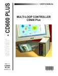
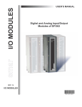
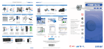
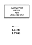
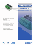
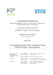
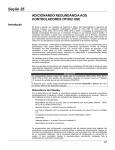
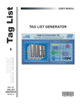
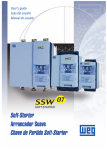
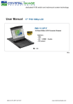
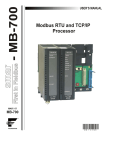
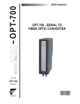
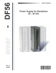
USER’S MANUAL Panel Interfaces Panel Interfaces I T F P A N E L ME smar www.smar.com Specifications and information are subject to change without notice. Up-to-date address information is available on our website. web: www.smar.com/contactus.asp Preventing Electrostatic Discharge PREVENTING ELECTROSTATIC DISCHARGE WARNING Electrostatic discharges can damage semiconductor electronic components present in printed circuit boards. In general, they occur when these components or the module connecting pins and racks are touched without the use of equipment to prevent electrostatic discharges. The following procedures are recommend: Before handling the modules and racks, discharge the static electricity contained in the body through proper bracelets or even touching grounded objects. Avoid touching electronics components or rack and module connecting pins. III Interface Panels – User Manual IV Introduction INTRODUCTION Reducing the Panel Mounting Time The panel mounting is reduced to a time fraction, in comparison to the traditional method. The cables are available with connectors suitable for interfaces and I/O modules. The interfaces increase the capacity of the I/O modules with terminal blocks, LED status indicators on the field, diagnostic, insulation circuit, over current protection and also increase the output capacity. Several cable sizes are available. Reduction Wiring Errors The system provides 100% pre-tested cables, allowing only the correct wire connection and eliminating the need of wire point-to-point check. With Smar interfaces there is a significant reduction in the panel mounting time if compared to traditional terminal blocks and prevent wiring errors, which can take several minutes to fix after the panel is ready. Easy Maintenance and Troubleshooting Normal terminal blocks may not offer the benefits of the interfaces, such as the field LED status indicator for each point. The new system facilitates the plant startup and troubleshooting and maintenance. Diagnoses like indications of burning fuses and field status LED allow to quickly locate failures and reduce the plant starting time and increase productivity. Productivity Increase With Smar interfaces the panel mounting time is shorter if compared to traditional terminal blocks. The ready cables eliminate costs and reduce cutting and connecting time, as well as routing and setting them in the conduits. Thus, engineering and assemblers need only to worry about one cable, instead of 20 conductors in the conventional process. Simplifying the Panel Design Engineering can simplify their panel drawings, specifying the interface and the cable, rather than specifying in detail the wire, cable markers, terminal block, accessories and their designs. The simplified designs not only help in the assembly, but also in maintenance. Panel Visual Quality The identification labels on the interface and the new cables organize the panel wiring and improve its aspect. V Interface Panels – User Manual VI Table of Contents TABLE OF CONTENTS INTERFACE MODULES ............................................................................................................................. 1.1 INTERFACE FOR 120/240 VAC 16 POINTS INPUT .................................................................................................... 1.3 ORDERING CODE ................................................................................................................................................................ 1.3 DESCRIPTION ...................................................................................................................................................................... 1.3 TECHNICAL SPECIFICATIONS ........................................................................................................................................... 1.3 INTERFACE FOR 24 VDC 16 POINTS INPUT............................................................................................................. 1.5 ORDERING CODE ................................................................................................................................................................ 1.5 DESCRIPTION ...................................................................................................................................................................... 1.5 TECHNICAL SPECIFICATIONS ........................................................................................................................................... 1.5 INTERFACE FOR 16 POINT AC PULSE INPUT .......................................................................................................... 1.7 ORDERING CODE ................................................................................................................................................................ 1.7 DESCRIPTION ...................................................................................................................................................................... 1.7 TECHNICAL SPECIFICATIONS ........................................................................................................................................... 1.7 INTERFACE FOR 16 POINTS RELAY DIGITAL OUTPUT WITH NA AND NC CONTACT ........................................ 1.9 ORDERING CODE ................................................................................................................................................................ 1.9 DESCRIPTION ...................................................................................................................................................................... 1.9 TECHNICAL SPECIFICATIONS ........................................................................................................................................... 1.9 INTERFACE FOR 16-POINT RELAY DIGITAL OUTPUT WITH NA AND NC CONTACT WITH FUSE .................... 1.12 ORDERING CODE .............................................................................................................................................................. 1.12 DESCRIPTION .................................................................................................................................................................... 1.12 TECHNICAL SPECIFICATIONS ......................................................................................................................................... 1.12 INTERFACE FOR 8-POINT ANALOG INPUT/OUTPUT ............................................................................................ 1.15 ORDERING CODE .............................................................................................................................................................. 1.15 DESCRIPTION .................................................................................................................................................................... 1.15 TECHNICAL SPECIFICATIONS ......................................................................................................................................... 1.15 INTERFACE FOR 8-POINT ANALOG INPUT (LOW LEVEL/TEMPERATURE SIGNALS) ....................................... 1.17 ORDERING CODE .............................................................................................................................................................. 1.17 DESCRIPTION .................................................................................................................................................................... 1.17 INTERFACE FOR 8-POINT ANALOG OUTPUT (VOLTAGE/CURRENT) ................................................................. 1.19 ORDERING CODE .............................................................................................................................................................. 1.19 DESCRIPTION .................................................................................................................................................................... 1.19 TECHNICAL SPECIFICATIONS ......................................................................................................................................... 1.19 INTERFACE FOR 8-POINT DIGITAL OUTPUT RELAY WITH NA AND NF CONTACT WITH FUSE ...................... 1.21 ORDERING CODE .............................................................................................................................................................. 1.21 DESCRIPTION .................................................................................................................................................................... 1.21 TECHNICAL SPECIFICATIONS ......................................................................................................................................... 1.21 10-POINT INTERFACE FOR POWER SUPPLY DISTRIBUTION .............................................................................. 1.23 ORDERING CODE .............................................................................................................................................................. 1.23 DESCRIPTION .................................................................................................................................................................... 1.23 TECHNICAL SPECIFICATIONS ......................................................................................................................................... 1.23 DIODE MATRIX INTERFACE ..................................................................................................................................... 1.24 ORDERING CODE .............................................................................................................................................................. 1.24 DESCRIPTION .................................................................................................................................................................... 1.24 TECHNICAL SPECIFICATIONS ......................................................................................................................................... 1.24 DIODE FOR DECOUPLING OF POWER SUPPLY FOR REDUNDANCY ................................................................ 1.25 ORDERING CODE .............................................................................................................................................................. 1.25 DESCRIPTION .................................................................................................................................................................... 1.25 TECHNICAL SPECIFICATIONS ......................................................................................................................................... 1.25 INSTALLATION ................................................................................................................................................................... 1.26 INTERFACE FOR 16-POINT INPUT/OUTPUT DIGITAL 24 VDC .............................................................................. 1.27 ORDERING CODE .............................................................................................................................................................. 1.27 DESCRIPTION .................................................................................................................................................................... 1.27 TECHNICAL SPECIFICATIONS ......................................................................................................................................... 1.27 INTERFACE FOR 8-POINTS ANALOG INPUT/OUTPUT .......................................................................................... 1.30 ORDERING CODE .............................................................................................................................................................. 1.30 DESCRIPTION .................................................................................................................................................................... 1.30 TECHNICAL SPECIFICATIONS ......................................................................................................................................... 1.30 INTERFACE FOR CD600PLUS .................................................................................................................................. 1.33 ORDERING CODE .............................................................................................................................................................. 1.33 TECHNICAL SPECIFICATIONS FOR ANALOG OUTPUT 8-POINT INTERFACE ............................................................. 1.34 TECNICAL SPECIFICATIONS FOR DIGITAL 8-INPUT INTERFACE ................................................................................ 1.34 VII Interface Panels – User Manual TECHNICAL SPECIFICATIONS FOR 24 VDC DIGITAL OUTPUT 8-POINT INTERFACE COMPATIBLE WITH NA AND NF CONTACT RELAY WITH FUSE FOR THE ITF-CD-A/C ..................................................................................................... 1.35 SPART PART COMPONENTS ................................................................................................................................... 1.42 CONNECTION CABLES ............................................................................................................................................. 1.42 ORDERING CODE .............................................................................................................................................................. 1.42 DESCRIPTION .................................................................................................................................................................... 1.42 TECHNICAL SPECIFICATIONS ......................................................................................................................................... 1.43 BASIC RULES FOR PANEL MOUNTING................................................................................................................... 1.43 INSTALLATION CONDITION .............................................................................................................................................. 1.43 DIMENSIONS ...................................................................................................................................................................... 1.44 VIII Section 1 INTERFACE MODULES Interfaces make possible to eliminate the difficult work of making cables, attaching washers and assembling terminal blocks. Simply plug the interface in the DIN rail and connect the cable. It is easy and fast! The Smar interfaces for panel are available with various features that will suit your application. They are designed for Smar I/O modules. Here is a list of interfaces offered by Smar: CODE ITF - 005AC1 ITF - 005AC2 ITF - 001 ITF - 005DC ITF - 101 ITF – 101FAC ITF – 101FDC ITF – 102 ITF – 102FAC ITF – 102FDC ITF – 120AC ITF – 120DC ITF – 123-7 ITF – 1237FAC ITF – 1237FDC ITF – 304 ITF – 401 ITF – 402 ITF – 501 ITF – QDA-AC ITF – QDA-DC ITF – D-12 ITF – DR ITF-DIG ITF-AN-IOR ITF-CD-0 ITF-CD-A ITF-CD-D ITF - C-10 ITF - C-15 ITF - C-20 ITF - C-25 ITF - C-30 ITF - C-35 ITF - C-40 ITF - C-45 ITF - C-50 ITF-CDE-0 ITF-CDE-1 ITF-CDE-2 ITF-CDE-3 DESCRIPTION Interface for 16 points of 120 Vac input compatible with M-005/DF15. Interface for 16 points of 240 Vac input compatible with M-005/DF15. Interface for 16 points of 24 Vdc input compatible with M-001/DF11. Interface for 16 points of 24 Vdc input compatible with M-005/DF15. Interface for 16 points digital output for relay with NA and NC contact compatible M-101/DF21. Interface for 16 points digital output for relay with NA and NC contact with fuse for AC load compatible with M-101/DF21. Interface for 16 points digital output for relay with NA and NC contact with fuse for DC load compatible with M-101/DF21. Interface for 16 points digital output for relay with NA and NC contact compatible M-102/DF22. Interface for 16 points digital output for relay with NA and NC contact with fuse for AC load compatible with M-102/DF22. Interface for 16 points digital output relay for relay with NA and NC contact with fuse for DC load compatible with M-102/DF22. Interface for 8 points digital output for AC load relay compatible with M-120/DF25. Interface for 8 points digital output for DC load relay compatible with M-120/DF25. Interface for 16 points digital output for relay with NA and NC contact compatible for AC load with M123/DF28 or M-127/DF69. Interface for 16 points digital output for relay with NA and NC contact with fuse for AC load compatible with M-123/DF28 or M-127/DF69. Interface for 16 points digital output for relay with NA and NC contact with fuse for DC load compatible with M-123/DF28 or M-127/DF69. Interface for 16 point AC pulse input compatible with M-304/DF67. Interface for 8 point analog input/output compatible with M-401-R/DF44, M-401-DR/DF57, DF116 and DF117. Interface for 8 point analog input (low level signal/temperature) compatible with M-402/DF45. Interface for 8 point analog output (voltage/current) compatible with M-501/DF46. Power distribution interface for 10 points 110/240 Vac @ 2A per point. Power distribution interface for 10 points 24 Vdc @ 2A per point. Diode matrix Interface for 12 bulbs test. Diode for decoupling of power supply for redundancy. Interface for 16 digital input/output points 24 Vdc. Interface for 8 analog input/output points compatible with DF113 and DF114. Interface for CD600 Plus, digital output without fuse. Interface for CD600 Plus, digital output with fuse, for AC load. Interface for CD600 Plus, digital output with fuse, for DC load. Connection cable between LC700/DFI302 modules and ITF interfaces - 1.0 m. Connection cable between LC700/DFI302 modules and ITF interfaces - 1.5 m. Connection cable between LC700/DFI302 modules and ITF interfaces - 2.0 m. Connection cable between LC700/DFI302 modules and ITF interfaces - 2.5 m. Connection cable between LC700/DFI302 modules and ITF interfaces - 3.0m. Connection cable between LC700/DFI302 modules and ITF interfaces - 3.5 m. Connection cable between LC700/DFI302 modules and ITF interfaces - 4.0 m. Connection cable between LC700/DFI302 modules and ITF interfaces - 4.5 m. Connection cable between LC700/DFI302 modules and ITF interfaces - 5.0 m. Connection cable between CD6000plus (left) and interfaces ITF – 0.5 m length. Connection cable between CD6000plus (left) and interfaces ITF –1.0 m length. Connection cable between CD6000plus (left) and interfaces ITF – 1.5 m length Connection cable between CD6000plus (left) and interfaces ITF – 2.0 m length 1.1 Interfaces for Panels – User Manual CODE ITF-CDE-4 ITF-CDE-5 ITF-CDE-6 ITF-CDE-7 ITF-CDE-8 ITF-CDE-9 ITF-CDD-0 ITF-CDD-1 ITF-CDD-2 ITF-CDD-3 ITF-CDD-4 ITF-CDD-5 ITF-CDD-6 ITF-CDD-7 ITF-CDD-8 ITF-CDD-9 ITF - CR-10 ITF - CR-15 ITF - CR-20 ITF - CR-25 ITF - CR-30 ITF - CR-35 ITF - CR-40 ITF - CR-45 ITF - CR-50 1.2 DESCRIPTION Connection cable between CD6000plus (left) and interfaces ITF – 2.5 m length Connection cable between CD6000plus (left) and interfaces ITF – 3.0 m length Connection cable between CD6000plus (left) and interfaces ITF – 3.5 m length Connection cable between CD6000plus (left) and interfaces ITF – 4.0 m length Connection cable between CD6000plus (left) and interfaces ITF – 4.5 m length Connection cable between CD6000plus (left) and interfaces ITF – 5.0 m length Connection cable between CD6000plus (right) and interfaces ITF – 0.5 m length Connection cable between CD6000plus (right) and interfaces ITF – 1.0 m length Connection cable between CD6000plus (right) and interfaces ITF – 1.5 m length Connection cable between CD6000plus (right) and interfaces ITF – 2.0 m length Connection cable between CD6000plus (right) and interfaces ITF – 2.5 m length Connection cable between CD6000plus (right) and interfaces ITF – 3.0 m length Connection cable between CD6000plus (right) and interfaces ITF – 3.5 m length Connection cable between CD6000plus (right) and interfaces ITF – 4.0 m length Connection cable between CD6000plus (right) and interfaces ITF – 4.5 m length Connection cable between CD6000plus (right) and interfaces ITF – 5.0 m length Connection cable between DFI302 R-Series modules and Interfaces ITF – 1.0 m lenght Connection cable between DFI302 R-Series modules and Interfaces ITF – 1.5 m lenght Connection cable between DFI302 R-Series modules and Interfaces ITF – 2.0 m lenght Connection cable between DFI302 R-Series modules and Interfaces ITF – 2.5 m lenght Connection cable between DFI302 R-Series modules and Interfaces ITF – 3.0 m lenght Connection cable between DFI302 R-Series modules and Interfaces ITF – 3.5 m lenght Connection cable between DFI302 R-Series modules and Interfaces ITF – 4.0 m lenght Connection cable between DFI302 R-Series modules and Interfaces ITF – 4.5 m lenght Connection cable between DFI302 R-Series modules and Interfaces ITF – 5.0 m lenght Interfaces Modules Interface for 120/240 VAC 16 Points Input Ordering Code ITF - 005AC1 - Interface for 120 VAC 16 points input compatible with M-005/DF15. ITF - 005AC2 - Interface for 240 VAC 16 points input compatible with M-005/DF15. Description This module reads the AC input tension and converts it to a logical true signal (ON) or false (OFF) 0 at 24 Vdc, compatible with the M-005/DF15 module inputs. Figure 1 – Interface for the ITF Panel - 005AC2 Technical Specifications ARCHITECTURE Input Number 16 ISOLATION Optical Isolation 5000 Vac EXTERNAL SOURCE TO AC INPUT 120 Vac (ITF - 005AC1) Input power supply 240 Vac (ITF - 005AC2) Typical per point consumption 10 mA External source indication Green LED Input power supply Maximum consumption External source indication Protection DC AUXILIARY SOURCE 22 - 30 Vdc 220 mA : ITF-005AC1 540 mA : ITF-005AC2 Green LED Polarity INPUT Typical current input 100 – 140 Vac (ITF - 005AC1) 200 – 264 Vac (ITF - 005AC2) 0 - 30 Vac (ITF - 005AC1) 0 - 50 Vac (ITF - 005AC2) 10 mA @ nominal voltage Status indication Yellow LED Voltage range for logical "1" level Voltage range for logical "0" level VOLTAGE PROTECTION PROVIDED FOR SENSORS Fuse per input Burning fuse Indication * *For burning fuse indication the load must be connected. 100 mA Red LED 1.3 Interfaces for Panels – User Manual Minimum voltage for a logic "1" Maximum voltage for a logic "0" Typical hysteresis “0” to “1” response time “1” to “0” response time INFORMATION SWITCHING 100 Vac (ITF - 005AC1), 45 to 60 Hz 200 Vac (ITF - 005AC2), 45 to 60 Hz 30 Vac (ITF - 005AC1), 45 to 60 Hz 50 Vac (ITF - 005AC2), 45 to 60 Hz 70 Vac (ITF - 005AC1) 150 Vac (ITF - 005AC2) 5 ms 42 ms FIELD CONNECTION 2 Two terminals up to two-wire input (1,5 mm ). Mounting Dimensions (L x W x H)* *For more details see Figure 26. MECHANICAL INFORMATION DIN rail (347 x 89.6 x 70) mm Figure 2 – ITF-005AC1 Interconnection Diagram 1.4 Interfaces Modules Interface for 24 Vdc 16 Points Input Ordering Code ITF - 001 - Interface for 24 Vdc 16 points input compatible with M-001/DF11 ITF - 005DC - Interface for 24 Vdc 16 points input compatible with M-005/DF15 Description Interface has 16 DC digital inputs compatible with the M-001/DF11 and M-005/DF15. Figure 3 – ITF – 001 Interface for Panel Technical Specifications ARCHITECTURE Input Number 16 Input power supply Maximum consumption External source indication Protection DC AUXILIARY SOURCE 22 - 30 Vdc 200 mA @ 24 Vdc Green LED Polarity VOLTAGE PROTECTION PROVIDED FOR SENSORS Fuse per input 100 mA Burning fuse indication* * For burning fuse indication the load must be connected. Red LED INPUTS Per-point input current Status indication 8 mA @ 24 Vdc Yellow LED CONNECTION FOR FIELD 2 terminal blocks providing power to the sensor (positive and negative) and 1 for each input. Up to 2 wires (1.5 mm²) per terminal. MECHANICAL INFORMATION Mounting Dimensions (L x W x H)* * For more details see Figure 40. DIN rail (290 x 89.6 x 70) mm 1.5 Interfaces for Panels – User Manual Figure 4 – ITF-001 Interconnection Diagram 1.6 Interfaces Modules Interface for 16 Point AC Pulse Input Ordering Code ITF - 304 - Interface for 16 point AC pulse input compatible with M-304/DF67. Description Interface has 16 AC pulse inputs compatible with the M-304/DF67. Figure 5 – ITF-304 Interface for Panel Technical Specifications ARCHITECTURE Input Number Input power supply Maximum consumption External source indication Protection 16 DC AUXILIARY SOURCE 22 - 30 Vdc 200 mA @ 24 Vdc Green LED Polarity CONNECTION FOR FIELD 2 terminal blocks providing power to the sensor (positive and negative) and 1 for each input. Up to 2 wires (1.5 mm²) per terminal. MECHANICAL INFORMATION Mounting Dimensions (L x W x H)* * For more details see Figure 40. DIN rail (290 x 89.6 x 70) mm 1.7 Interfaces for Panels – User Manual Figure 6 – ITF-304 Interconnection Diagram 1.8 Interfaces Modules Interface for 16 Points Relay Digital Output with NA and NC Contact Ordering Code ITF - 101 - Interface for 16-point digital output relay with NA and NC compatible with M-101/DF21. ITF - 102 - Interface for 16-point digital output relay with NA and NC compatible with M-102/DF22. ITF - 123-7 - Interface for 16-point digital output relay with NA and NC compatible with M-123/DF28, M127/DF69. Description This interface connects the outputs of the modules corresponding to the relay coil. Figure 7 – ITF-123-7 Interface Panel Technical Specifications ARCHITECTURE Output Number Power supply source 16 DC AUXILIARY SOURCE 20 - 30 Vdc Maximum current 450 mA @ 24 Vdc: ITF-101 500 mA @ 24 Vdc: ITF-102 530 mA @ 24 Vdc: ITF-123-7 Indication Protection Green LED Polarity Input power supply Maximum consumption External source indication Protection DC AUXILIARY SOURCE 22 - 30 Vdc 200 mA @ 24 Vdc Green LED Polarity 1.9 Interfaces for Panels – User Manual OUTPUTS 1 NA contact , 1 NF contact, 3 terminals / output Vac range Vdc range Maximum current for 250 Vac Maximum current for 30 Vdc Leakage 1 NA contact , 1NF contact 20 – 250 Vac 20 – 110 Vdc 2 A (resistive); 2 A (indutive) 2 A (resistive); 2 A (indutive) No M-127: 500 μA @ 100 Vac Overload protection per output Must be provided externally Indication burning fuse* Red LED Operation time 10 ms (maximum) Mechanical Life - switching cycles 20.000.000 operations (min.) @ current (max). Status indication Yellow LED Relay Sockets Yes CONNECTION FOR FIELD 3 terminal: common, NC and NO. Up to 2 wires (1.5 mm²) per terminal. MECHANICAL INFORMATION Mounting Dimensions (L x W x H)* * For more details see Figure 40. 1.10 DIN rail (290 x 89.6 x 70) mm Interfaces Modules Figure 8 – ITF-101 Interconnection Diagram 1.11 Interfaces for Panels – User Manual Interface for 16-point Relay Digital Output with NA and NC Contact with Fuse Ordering Code ITF - 101FAC - Interface for 16-point relay digital output with NA and NC compatible with M-101/DF21 ITF - 101FDC - Interface for 16-point relay digital output with NA and NC compatible with M-101/DF21 ITF - 102FAC - Interface for 16-point relay digital output with NA and NC compatible with M-101/DF22 ITF - 102FDC - Interface for 16-point relay digital output with NA and NC compatible with M-102/DF22 ITF - 1237FAC - Interface for 16-point relay digital output with NA and NC compatible with M-123/DF28, M-127/DF69 ITF - 1237FDC - Interface for 16-point relay digital output with NA and NC compatible with M-123/DF28, M-127/DF69 with fuse for AC load with fuse for DC load with fuse for AC load with fuse for DC load with fuse for AC load with fuse for DC load Description This interface connects the outputs of the modules corresponding to the relay coil. Figure 9 – ITF-102FAC Interface Panel Technical Specifications ARCHITECTURE Output Number Power Supply 1.12 16 DC AUXILIARY SOURCE 20 - 30 Vdc Maximum Current ITF - 101FAC/DC:420 mA @ 24 Vdc ITF - 102FAC/DC: 480 mA @ 24 Vdc ITF - 1237FAC/DC: 550 mA @ 24 Vdc Indication Protection Green LED Polarity Interfaces Modules OUTPUTS 1 NA contact , 1 NF contact, 3 terminals / output Vac range Vdc range Maximum current for 250 Vac Maximum current for 30 Vdc 1 NA contact , 1NF contact 20 – 250 Vac 20 – 110 Vdc 2 A (resistive); 2 A (indutive) 2 A (resistive); 2 A (indutive) Leakage No Overload protection per output Fuse (2A) Burning fuse indication * Red LED Operation time 10 ms (maximum) Mechanical Life - switching cycles 20.000.000 operations (min.) @ current (max). Status indication Yellow LED Relay sockets Yes *For burning fuse indication the load must be connected. CONNECTION FOR FIELD 3 terminals: common, NC and NO. Up to 2 wires (1.5 mm²) per terminal. MECHANICAL INFORMATION Mounting Dimensions (L x W x H)* * For more details see Figure 40. DIN rail (290 x 89.6 x 70) mm 1.13 Interfaces for Panels – User Manual Figure 10 – ITF-101-FAC Interconnection Diagram 1.14 Interfaces Modules Interface for 8-point Analog Input/Output Ordering Code ITF - 401 - Interface for 8-point analog input/output compatible with M-401-R/DF44, M-401-DR/DF57, DF116 e DF117. Description The interface has 8-point analog input/output points to connect to M-401R/DF44, M-401-DR/DF57, DF116 e DF117. Figure 11 – ITF-401 Interface Panel Technical Specifications DC AUXILIARY SOURCE 20 – 30 Vdc (output) 22 - 30 Vdc (input) 200 mA @ 24 Vdc Green LED Polarity External source Maximum consumption Indication Protection INPUTS/OUTPUTS Current per point 22 mA @ 24 Vdc VOLTAGE PROTECTION PROVIDED FOR SENSORS Fuse per point 100 mA Burning fuse Indication * *For burning fuse indication the load must be connected. Red LED CONNECTION FOR FIELD 3 terminals: common, NC and NO. Up to 2 wires (1.5 mm²) per terminal. MECHANICAL INFORMATION Mounting Dimensions (L x W x H)* * For more details see Figure 40. DIN rail (146 x 89.6 x 70) mm 1.15 Interfaces for Panels – User Manual Figure 12 – ITF-401 Interconnection Diagram 1.16 Interfaces Modules Interface for 8-Point Analog Input (Low Level/Temperature Signals) Ordering Code ITF - 402 - Interface for 8-point analog input (low level/temperature) compatible with M-402/DF45. Description The interface has 8-point analog input to connect to M-402/DF45. Figure 13 – ITF-402 Interface Panel CONNECTION FOR FIELD Up to 2 wires (1.5 mm²), 3 terminals per input. MECHANICAL INFORMATION Mounting Dimensions (L x W x H)* * For more details see Figure 40. DIN rail (290 x 89.6 x 70) mm 1.17 Interfaces for Panels – User Manual Figure 14 – ITF-402 Interconnection Diagram 1.18 Interfaces Modules Interface for 8-Point Analog Output (Voltage/Current) Ordering Code ITF - 501 - Interface for 8-point analog output (voltage/current) compatible with M-501/DF46. Description The interface has 8-point analog output to connect to M-501/DF46. Figure 15 – ITF-501 Interface Panel Technical Specifications ARCHITECTURE Output Number 8 DC AUXILIARY SOURCE “In Rush” Current External Source Maximum Current Indication Protection 2,3 A, 10ms (maximum) @ 24 Vdc 20 - 30 Vdc 200 mA Yes Polarity OUTPUTS Posts Diode to measure the output current Two terminals for each output. Yes, in the current outputs CONNECTION FOR FIELD Up to 2 wires (1.5 mm²), 3 terminals per input. MECHANICAL INFORMATION Mounting Dimensions (L x W x H)* * For more details see Figure 40. DIN rail (290 x 89.6 x 70) mm 1.19 Interfaces for Panels – User Manual Figure 16 – ITF-501 Interconnection Diagram 1.20 Interfaces Modules Interface for 8-Point Digital Output Relay with NA and NF Contact with Fuse Ordering Code ITF - 120FAC - Interface for 8-point digital output relay to AC load compatible with M-120/DF25. ITF - 120FDC - Interface to 8-point digital output relay to AC load compatible with M-120/DF25. Description This interface connects the M-120/DF25 module outputs to the relay coil. Figure 17 – ITF-120 Interface Panel Technical Specifications ARCHITECTURE Output Number 8 DC AUXILIARY SOURCE Power Supply Maximum Current Indication Protection 20 – 30 Vdc 280 mA @ 24 Vdc Green LED Polarity OUTPUTS 2 NA contact posts – per output Vac range Vdc range Maximum current for 250 Vac Maximum current for 30 Vdc Leakage 2 NA contact, 2 NF contact, 2 commons 20 – 250 Vac 20 – 110 Vdc 2 A (resistive); 2 A (indutive) 2 A (resistive); 2 A (indutive) No M-127: 500 μA @ 100 Vac Overload protection per output Fuse (2A) Burning fuse indication * Operation time Red LED 10 ms (maximum) 20.000.000 operations (min.) @ current (max). Yellow LED Yes Mechanical Life - switching cycles Status indication Relay socket *For burning fuse indication the load must be connected. CONNECTION FOR FIELD Up to 2 wires (1.5 mm²), 3 terminals per input. 1.21 Interfaces for Panels – User Manual MECHANICAL INFORMATION Mounting Dimensions (L x W x H)* * For more details see Figure 40. DIN rail (290 x 89.6 x 70) mm NOTE Note that there must be external protection against output overload. This protection is possible by inserting a fuse externally, as for example, terminals 7, 8 and 9 in the case of the left hand figure. The others already have internal protection. Figure 18 – ITF-120AC Interconnection Diagram 1.22 Interfaces Modules 10-point Interface for Power Supply Distribution Ordering Code ITF - QDA-AC - Power supply distribution table for 10-point AC load 110/240 VAC @ 2A per point interface, 2 A per point. ITF - QDA-DC - Power supply distribution table for 10-point DC load 24 Vdc @ 2A per point interface, 2 A per point. Description Interface for power supply distribution on panel. Figure 19 – ITF-QDA10-AC Interface Panel Technical Specifications ARCHITECTURE Output Number Identification Plate 10 External Source and output tags DC AUXILIARY SOURCE ITF – QDA-AC: 264 Vac ITF - QDA-DC: 30 Vdc Maximum external source OUTPUT Maximum Current per output Terminals Protection 2A 2 terminals for each output Fuse Burning fuse Indication * *For burning fuse indication the load must be connected. Red LED CONNECTION FOR FIELD 2 2 terminals per output, up to 2 wires (1,5 mm ) per terminal. MECHANICAL INFORMATION Mounting Dimensions (L x W x H)* * For more details see Figure 40. DIN rail (290 x 89.6 x 70) mm 1.23 Interfaces for Panels – User Manual Diode Matrix Interface Ordering Code ITF - D-12 - Diode Matrix Interface for 12 bulbs test Description Diode interface for lamp tests. Figure 20 – ITF-D12 Interface Panel Technical Specifications ARCHITECTURE Channel Number 1 group with 12 diodes CHANNEL Maximum external source Maximum current per channel 600 V 800 mA CONNECTION FOR FIELD 2 2 terminals per output, up to 2 wires (1.5 mm ) per terminal. MECHANICAL INFORMATION Mounting Dimensions (L x W x H)* * For more details see Figure 40. 1.24 DIN rail (290 x 89.6 x 70) mm Interfaces Modules Diode for Decoupling of Power Supply for Redundancy Ordering Code ITF-DR: Diode for Decoupling of Power Supply for Redundancy Description This interface can be used for decoupling of power supply, with the outputs in paralleled, with purpose of redundancy. • • Supports load up to 20A; Easy mounting in DIN rail. Figure 21 – ITF-DR Interface Panel Figure 22 – Pinning the ITF-DR Technical Specifications Input Voltage Un/Umáx Maximum Input Current *Using cable of 4mm² Transient Suppressor for Diode Reverse Polarity Protection Overcurrent Protection Input/Output Voltage Drop Operation Temperature Storage Temperature FUNCTIONAL SPECIFICATIONS 24/30 Vdc 1 x 20 A 2 x 10 A Yes Yes No. Provision should be made at source or externally Approximately 0.5 V 0 ºC to 60 ºC -20 ºC to 80 ºC CONNECTION 2 4 terminals, maximum 4 mm 1.25 Interfaces for Panels – User Manual MECHANICAL INFORMATION Mounting Dimensions (L x W x H)* * For more details see Figure 40. DIN rail (81 x 45 x 132) mm Installation The installation of the interface should be made to facilitate the horizontal convection. NOTE To ensure good air convection, use a minimum spacing between interfaces ITF-DR: - 12 cm (4.724 in) vertically; - 3 cm (1.181 in) horizontally; Mounting: Attach the top rail and press to lock the module. See Figure 23(a). Removing: Loosen the lock using a screwdriver and then disconnect the rail. See Figure 23(b). a) b) Figure 23 – Assembly (a) and Disassembly (b) of the ITF-DR Figure 24 – ITF-DR Interconnection Diagram 1.26 Interfaces Modules Interface for 16-point Input/Output Digital 24 Vdc Ordering Code ITF-DIG - Interface for 16-point Input/Output Digital 24 Vdc, compatible only with DFI302 R-Series, modules DF111 and DF112. Description The interface for 16-point inputs/outputs digital DC is used together rack DF110-2, compatible only with DFI302 R-Series line, modules DF111 and DF112. Figure 25 – ITF-DIG Interface for Panel Technical Specifications ARCHITECTURE Channel Number 16 External source (VEXT_A) External source (VEXT_B) Maximum consuption (VEXT_A) Maximum consuption (VEXT_B) External source indication Protection DC AUXILIARY SOURCE 20 - 30 Vdc (output) 22 - 30 Vdc (input) 20 - 30 Vdc (output) 22 - 30 Vdc (input) 850 mA @ 24 Vdc (output) 200 mA @ 24 Vdc (input) 850 mA @ 24 Vdc (output) 200 mA @ 24 Vdc (input) LED Green Polarity VOLTAGE PROTECTION PROVIDED TO SENSORS Fuse per point 100 mA Burning fuse Indication * * For burning fuse indication the load must be connected. Red LED INPUTS Input current per point 8 mA @ 24 Vdc OUTPUTS Maximum output current per point 50 mA @ 24 Vdc 1.27 Interfaces for Panels – User Manual CONNECTION 2 terminals supplying VEXT (positive and negative) and 1 for each input/output. 2 Up to two wires (1.5 mm ) per terminal. MECHANICAL INFORMATIONS Trilho DIN (290 x 89.6 x 70) mm Mounting Dimensions (L x W x H)* * For more details see Figure 40. NOTE The power supply tension applied to the CN1 (VEXT-A) connector will power the redundant pair left I/O module, while the power supply tension applied to the CN2 (VEXT-B) will power the redundant pair right I/O module. For redundancy to be available on the level of the external power supply sources, the interface must be activated by two separate external power supply sources, one for the VEXT_A and the other for the VEXT_B. When to be used by only one external power supply source, activate both VEXT_A and VEXT_B connectors, so that both redundant pair modules will be powered. FIELD INTERIOR PANEL GND 17 +24Vcc 18 IN 19 GND 20 +24Vcc 21 IN 22 GND 23 +24Vcc 24 IN 25 GND 26 +24Vcc 27 IN GND 29 +24Vcc SENSOR S 30 IN - 31 GND + 32 +24Vcc SENSOR S 33 IN - 34 GND +24Vcc SENSOR SENSOR SENSOR SENSOR - SENSOR + 35 S 36 - 37 GND + 38 +24Vcc S 39 IN - 40 GND +24Vcc IN + 41 S 42 IN - 43 GND + 44 +24Vcc S 45 IN - 46 GND + 47 +24Vcc S 48 IN - 49 GND + 50 +24Vcc S 51 IN - 52 GND VEXT_B VEXT_A DI_01 DI_03 IN 16 DI_02 PIN_18 DI_03 PIN_20 DI_04 DI_04 15 DI_01 PIN_17 PIN_21 DI_05 PIN_22 DI_06 PIN_23 DI_07 PIN_3 DI_08 PIN_4 DI_09 PIN_5 DI_10 DI_02 4 DI_05 +24Vcc SMAR DI_06 GND 14 DI - DF111 POSITIVE NEGATIVE DI_07 13 NEGATIVE PIN_16 INTERFACE CABLE DI_08 IN RACK SLAVE ___ - PAR ___ DI_00 DI_09 +24Vcc POSITIVE PIN_15 GND DI_10 GND 11 12 2 3 PIN_6 DI_11 PIN_8 DI_12 PIN_9 DI_13 PIN_10 DI_14 PIN_11 DI_15 PIN_1 DI_11 10 GND VEXT_A PIN_2 PIN_7 DI_12 IN 1 24Vcc IN VEXT_B PIN_14 DI_13 9 28 + 1N4007 +24Vcc 24Vcc IN PIN_12 PIN_13 DI_14 EXAMPLE GND 8 + SENSOR NOTE: When the PLC contact is to be used on an inductive circuit with continuous voltage, the client should install a diode in parallel with the coils. IN 7 DI_15 6 +24Vcc DI_00 RACK DF110-2 5 PIN_19 GND PIN_24 ITF-DIG PIN_25 Figure 26 – ITF-DIG Interconnection Diagram with DF111 Module 1.28 Interfaces Modules FIELD INTERIOR PANEL + 1N4007 - 15 OUT 16 GND 17 +24Vcc 18 OUT 19 GND 20 +24Vcc 21 OUT 22 GND 23 +24Vcc 24 OUT 25 GND 26 +24Vcc 27 OUT 28 GND 29 +24Vcc 30 OUT 31 GND 32 +24Vcc 33 OUT 34 GND 35 +24Vcc 36 OUT 37 GND 38 +24Vcc 39 OUT 40 GND 41 +24Vcc 42 OUT 43 GND 44 +24Vcc 45 OUT 46 GND 47 +24Vcc 48 OUT 49 GND 50 +24Vcc 51 OUT 52 GND DO_00 DO_01 DO_02 PIN_17 DO_02 PIN_18 DO_03 DO_03 +24Vcc PIN_20 DO_04 DO_04 GND 14 PIN_21 DO_05 PIN_22 DO_06 DO_05 13 PIN_16 DO_01 PIN_23 DO_07 PIN_3 DO_06 OUT DO_07 +24Vcc SMAR PIN_15 DO_00 DO_08 PIN_4 DO_09 PIN_5 DO_10 INTERFACE CABLE DO_08 GND 11 12 4 DO_09 10 GND DO - DF112 POSITIVE NEGATIVE PIN_6 DO_11 PIN_8 DO_12 PIN_9 DO_13 PIN_10 DO_14 DO_10 OUT 2 3 RACK SLAVE ___ - PAR ___ PIN_11 DO_15 PIN_1 DO_11 9 GND 24Vcc IN POSITIVE NEGATIVE VEXT_A PIN_2 PIN_7 DO_12 +24Vcc 1 VEXT_B PIN_14 DO_13 EXAMPLE GND 8 24Vcc IN PIN_12 PIN_13 DO_14 NOTE: When the PLC contact is to be used on an inductive circuit with continuous voltage, the client should install a diode in parallel with the coils. OUT 7 DO_15 6 +24Vcc VEXT_B VEXT_A RACK DF110-2 5 PIN_19 GND PIN_24 ITF-DIG PIN_25 Figura 27 – ITF-DIG Interconnection Diagram with DF112 Module NOTE Do not connect the cable shield to the device ground (clip it). 1.29 Interfaces for Panels – User Manual Interface for 8-points Analog Input/Output Ordering Code ITF-AN-IOR - Interface for 8-point Analog Input/Output, compatible only with DFI302 R-Series, modules DF113 and DF114. Description The interface for 8-point analog input/output is used together rack DF110-2, compatible only with the DFI302 R-Series modules, DF113 and DF114. Figure 28 – ITF-AN-IOR Interface for Panel Technical Specifications ARCHITECTURE Channel Number 8 External source (VEXT_A) External source (VEXT_B) Maximum consuption (VEXT_A) Maximum consuption (VEXT_B) Indication Protection DC AUXILIARY SOURCE 20 - 30 Vdc (output) 22 - 30 Vdc (input) 20 - 30 Vdc (output) 22 - 30 Vdc (input) 250 mA @ 24 Vdc (output) 250 mA @ 24 Vdc (input) 250 mA @ 24 Vdc (output) 250 mA @ 24 Vdc (input) LED verde Polaridade INPUT/OUTPUT Maximum current per point 22 mA @ 24 Vdc VOLTAGE PROTECTION PROVIDED TO SENSORS Fuse per point 100 mA Burning fuse Indication * *For burning fuse indication the load must be connected. Red LED CONNECTION 2 terminals supplying VEXT (positive and negative) and 1 for each input/output. 2 Up to two wires (1.5 mm ) per terminal. 1.30 Interfaces Modules MECHANICAL INFORMATIONS Mounting DIN rail Dimensions (L x W x H)* (146 x 89.6 x 70) mm * For more information see Figure 40. NOTE The power supply tension applied to the CN1 (VEXT-A) connector will power the redundant pair left I/O module, while the power supply tension applied to the CN2 (VEXT-B) will power the redundant pair right I/O module. For redundancy to be available on the level of the external power supply sources, the interface must be activated by two separate external power supply sources, one for the VEXT_A and the other for the VEXT_B. When to be used by only one external power supply source, activate both VEXT_A and VEXT_B connectors, so that both redundant pair modules will be powered. FIELD INTERIOR PANEL ANALOG GROUND BUS RACK DF110-2 RACK SLAVE___ - PAR ___ AI - DF113 + + 4 _ WIRE _ + + 4 _ WIRE _ + + 4 _ WIRE _ IN 10 GND 11 +24Vcc 12 IN 13 GND 14 +24Vcc 15 IN 16 GND 17 +24Vcc 18 IN 19 GND 20 +24Vcc 21 IN 22 GND 23 +24Vcc 24 IN 25 GND 26 +24Vcc 27 IN 28 GND VEXT_B VEXT_A 9 AI_01 +24Vcc 24Vcc IN 3 GND 4 NEGATIVE POSITIVE NEGATIVE PIN_15 AI_00 PIN_3 PIN_16 AI_01 PIN_4 PIN_17 AI_02 PIN_5 PIN_18 AI_02 GND 8 2 POSITIVE AI_03 PIN_6 PIN_20 AI_04 PIN_8 AI_03 7 GND PIN_21 INTERFACE CABLE AI_05 PIN_9 PIN_22 AI_04 + + 4 _ WIRE _ IN 1 AI_06 PIN_10 PIN_23 AI_05 + 2 WIRE _ 6 24Vcc IN PIN_11 AI_06 + 2 WIRE _ +24Vcc PIN_7 PIN_1 PIN_2 PIN_14 AI_07 VEXT_A VEXT_B PIN_12 AI_07 + 2 WIRE _ 5 AI_00 SMAR + 2 WIRE _ PIN_13 ITF-AN-IOR PIN_19 GND PIN_24 PIN_25 NOTE: NOT CONNECT THE CABLE SHIELD TO GROUND THE INSTRUMENT (SHEAR) Figure 29 – ITF-AN-IOR Interconnection Diagram with DF113 Module 1.31 Interfaces for Panels – User Manual INTERIOR PANEL FIELD ANALOG GROUND BUS RACK DF110-2 RACK SLAVE ___ - PAR ___ AO - DF114 10 GND 11 +24Vcc 12 OUT 13 GND 14 +24Vcc 15 OUT 16 GND 17 +24Vcc 18 OUT 19 GND 20 +24Vcc 21 OUT 22 GND 23 +24Vcc 24 OUT 25 GND 26 +24Vcc 27 OUT 28 GND VEXT_B VEXT_A AO_01 OUT GND 4 NEGATIVE PIN_3 POSITIVE PIN_16 NEGATIVE AO_00 AO_01 PIN_4 PIN_17 AO_02 PIN_5 PIN_18 AO_02 +24Vcc 2 3 AO_03 PIN_6 PIN_20 AO_04 PIN_8 AO_03 8 9 GND 24Vcc IN PIN_21 INTERFACE CABLE AO_05 PIN_9 PIN_22 AO_04 GND 1 PIN_15 AO_06 PIN_10 PIN_23 AO_05 OUT 7 24Vcc IN POSITIVE PIN_11 AO_06 6 PIN_7 PIN_1 PIN_2 PIN_14 AO_07 VEXT_A VEXT_B PIN_12 AO_07 +24Vcc AO_00 SMAR 5 PIN_13 PIN_19 ITF-AN-IOR GND PIN_24 PIN_25 NOTE: NOT CONNECT THE CABLE SHIELD TO GROUND THE INSTRUMENT (SHEAR) Figure 30 – ITF-AN-IOR Interconnection Diagram with DF114 Module NOTA Do not connect the cable shield to the device ground (clip it). 1.32 Interfaces Modules Interface for CD600plus Ordering Code ITF-CD-0: Interface for CD600plus, digital outputs without fuse; ITF-CD-A: Interface for CD600plus, digital outputs with fuse, for AC load; ITF-CD-D: Interface for CD600plus, digital outputs with fuse, for DC load. Figure 31 – ITF-CD-0 Interface for Panel (Digital outputs without fuse) Figure 32 – ITF-CD-A Interface for Panel (Digital outputs with fuse) Technical Specifications for Analog Input 8-Point Interface This interface has 8 inputs that are compatible with the controller 8 analog inputs. VOLTAGE PROVIDE FOR SENSORS Voltage selection for sensors, external power supply or controller power supply Using jumpers Individual protection by input Fuse 100 mA Burning fuse Indication* Red LED *For burning fuse indication the load must be connected. DC AUXILIARY SOURCE Power Supply Maximum Current Indication Protection 22 - 30 Vdc 200 mA @ 24 Vdc Green LED Polarity INPUTS Maximum per-point current input 22 mA @ 24 Vdc CONNECTION 3 terminals: auxiliary 24 Vdc input and ground. Up to two wires (1.5 mm²) per terminal. 1.33 Interfaces for Panels – User Manual Technical Specifications for Analog Output 8-Point Interface This interface has 8 outputs that are compatible with the controller analog outputs. ARCHITECTURE Output Number 8 SAÍDAS Terminals Diode to measure the output current Two terminals for each output Yes, on the output currents CONNECTION 2 terminals: analog output and ground Up to two wires (1.5 mm²) per terminal. Tecnical Specifications for Digital 8-Input Interface This interface has 8 inputs that are compatible with the controller digital inputs. ARCHITECTURE Output Number 8 DC AUXILIARY SOURCE Power Supply Maximum Current Indication Protection 22 - 30 Vdc 200 mA @ 24 Vdc Green LED Polarity VOLTAGE PROTECTION PROVIDE FOR SENSORS Fuse for input 100 mA Burning Fuse Indication * *For burning fuse indication the load must be connected. Red LED INPUTS Input current per point Status LED 2 mA @ 24 Vdc Yellow LED CONNECTION 3 terminals: 2 terminals supplying power to the positive and negative sensors and 1 for input. Up to two wires (1.5 mm²) per terminal. Technical Specifications for 24 Vdc Digital Output 8-Point Interface Compatible with NA and NF Contact Relay without Fuse for the ITF-CD0 Digital output 8-points interface to relay with NA and NF contacts, compatible with the controller digital outputs. ARCHITECTURE Output number Power Supply Maximum Current Indication Protection 1.34 8 DC AUXILIARY SOURCE 20 - 30 Vdc 225 mA @ 24 V Green LED Polarity Interfaces Modules OUTPUTS 1 NA contact, 1 NF contact, 3 terminal / output Vac range Vdc range Maximum current for 250 Vac Maximum current for 30 Vdc Leakage current Overload protection per output Burning Fuse Indication Operation time Mechanical life – switching cycles Status indication Relay sockets 1 NA contact, 1 NF contact 20 – 250 Vac 20 – 110 Vdc 2 A (resistive); 2 A (inductive) 2 A (resistive); 2 A (inductive) None M-127: 500 μA @ 100 Vac Must be provided externally Red LED 10 ms (maximum) 20.000.000 operations (min.) current (max). Yellow LED Yes @ CONNECTION 3 terminals: commom, NA contact and NF contact. Up to two wires (1.5 mm²) per terminal. Technical Specifications for 24 Vdc Digital Output 8-Point Interface Compatible with NA and NF Contact Relay with Fuse for the ITF-CDA/C Digital output 8-points interface for NA and NF contact relay, compatible with the controller digital outputs. ARCHITECTURE Output number Power Supply Maximum Current Indication Protection 8 DC AUXILIARY SOURCE 20 - 30 Vdc 280 mA @ 24 Vdc Green LED Polarity OUTPUT 1 NA contact, 1 NF contact, 3 terminal / output Vac range Vdc range Maximum current for 250 Vac Maximum current for 30 Vdc Leakage current Overload protection per output Burning Fuse Indication* Operation time Mechanical life – switching cycles Status indication Relay sockets *For burning fuse indication the load must be connected. 1 NA contact, 1 NF contact 20 – 250 Vac 20 – 110 Vdc 2 A (resistive); 2 A (inductive) 2 A (resistive); 2 A (inductive) None M-127: 500 μA @ 100 Vac Fuse (2A) Red LED 10 ms (maximum) 20.000.000 operations (min.) @ current (max). Yellow LED Yes CONNECTION 3 terminals: NF contact phase , NA contact phase and neutral. Up to two wires (1.5 mm²) per terminal. 1.35 Interfaces for Panels – User Manual Mounting Dimensions (L x W x H)* * For more details see Figure 40. MECHANICAL INFORMATION DIN rail (542.7 x 89.6 x 75.6) mm Figure 33 –ITF-CD-0 Analog Interconnection Diagram 1.36 Interfaces Modules Figure 34 –ITF-CD-0 Digital Interconnection Diagram 1.37 Interfaces for Panels – User Manual Figure 35 –ITF-CD-A Analog Interconnection Diagram 1.38 Interfaces Modules Figure 36 –ITF-CD-A Digital Interconnection Diagram 1.39 Interfaces for Panels – User Manual Figure 37 –ITF-CD-D Analog Interconnection Diagram 1.40 Interfaces Modules Figure 38 –ITF-CD-D Digital Interconnection Diagram 1.41 Interfaces for Panels – User Manual Spart Part Components LIST OF SPARE PARTS COMPONENTS DESCRIPTION Relay with 1 pole (package with 10 pieces); ITF-101/ITF-102/ITF-123-7 Relay with 2 poles (package with 10 pieces); ITF-120 Fuse 5 x 20 mm – 2A (package with 10 pieces); ITF Fuse 5 x 20 mm – 100 mA (package with 10 pieces); ITF Terminal block with 3 terminals (package with 10 pieces); ITF Terminal block with 2 terminals (package with 10 pieces); ITF Fuse carrier (package with 5 pieces); ITF CÓDE 400-1123 400-1124 400-1125 400-1126 400-1127 400-1128 400-1129 Connection Cables Ordering Code ITF - C-10 - Connection cable between LC700/DFI302 modules and ITF interfaces - 1.0 m length ITF - C-15 - Connection cable between LC700/DFI302 modules and ITF interfaces - 1.5 m length ITF - C-20 - Connection cable between LC700/DFI302 modules and ITF interfaces - 2.0 m length ITF - C-25 - Connection cable between LC700/DFI302 modules and ITF interfaces - 2.5 m length ITF - C-30 - Connection cable between LC700/DFI302 modules and ITF interfaces - 3.0 m length ITF - C-35 - Connection cable between LC700/DFI302 modules and ITF interfaces - 3.5 m length ITF - C-40 - Connection cable between LC700/DFI302 modules and ITF interfaces - 4.0 m length ITF - C-45 - Connection cable between LC700/DFI302 modules and ITF interfaces - 4.5 m length ITF - C-50 - Connection cable between LC700/DFI302 modules and ITF interfaces - 5.0 m length ITF - CDE-0 - Connection cable between CD6000plus (left) and interfaces ITF – 0.5 m lenght ITF - CDE-1 - Connection cable between CD6000plus (left) and interfaces ITF –1.0 m length ITF - CDE-2 - Connection cable between CD6000plus (left) and interfaces ITF – 1.5 m length ITF - CDE-3 - Connection cable between CD6000plus (left) and interfaces ITF – 2.0 m length ITF - CDE-4 - Connection cable between CD6000plus (left) and interfaces ITF – 2.5 m length ITF - CDE-5 - Connection cable between CD6000plus (left) and interfaces ITF – 3.0 m length ITF - CDE-6 - Connection cable between CD6000plus (left) and interfaces ITF – 3.5 m length ITF - CDE-7 - Connection cable between CD6000plus (left) and interfaces ITF – 4.0 m length ITF - CDE-8 - Connection cable between CD6000plus (left) and interfaces ITF – 4.5 m length ITF - CDE-9 - Connection cable between CD6000plus (left) and interfaces ITF – 5.0 m lenght ITF - CDD-0 - Connection cable between CD6000plus (right) and interfaces ITF – 0.5 m lenght ITF - CDD-1 - Connection cable between CD6000plus (right) and interfaces ITF – 1.0 m lenght ITF - CDD-2 - Connection cable between CD6000plus (right) and interfaces ITF – 1.5 m lenght ITF - CDD-3 - Connection cable between CD6000plus (right) and interfaces ITF – 2.0 m lenght ITF - CDD-4 - Connection cable between CD6000plus (right) and interfaces ITF – 2.5 m lenght ITF - CDD-5 - Connection cable between CD6000plus (right) and interfaces ITF – 3.0 m lenght ITF - CDD-6 - Connection cable between CD6000plus (right) and interfaces ITF – 3.5 m lenght ITF - CDD-7 - Connection cable between CD6000plus (right) and interfaces ITF – 4.0 m lenght ITF - CDD-8 - Connection cable between CD6000plus (right) and interfaces ITF – 4.5 m lenght ITF - CDD-9 - Connection cable between CD6000plus (right) and interfaces ITF – 5.0 m lenght ITF - CR-10 - Connection cable between DFI302 R-Series modules and Interfaces ITF – 1.0 m lenght ITF - CR-15 - Connection cable between DFI302 R-Series modules and Interfaces ITF – 1.5 m lenght ITF - CR-20 - Connection cable between DFI302 R-Series modules and Interfaces ITF – 2.0 m lenght ITF - CR-25 - Connection cable between DFI302 R-Series modules and Interfaces ITF – 2.5 m lenght ITF - CR-30 - Connection cable between DFI302 R-Series modules and Interfaces ITF – 3.0 m lenght ITF - CR-35 - Connection cable between DFI302 R-Series modules and Interfaces ITF – 3.5 m lenght ITF - CR-40 - Connection cable between DFI302 R-Series modules and Interfaces ITF – 4.0 m lenght ITF - CR-45 - Connection cable between DFI302 R-Series modules and Interfaces ITF – 4.5 m lenght ITF - CR-50 - Connection cable between DFI302 R-Series modules and Interfaces ITF – 5.0 m lenght Description Cables for interconnecting the interfaces to the Smar I/O modules. 1.42 Interfaces Modules ITF-C ITF-CR ITF-CDE ITF-CDD Figure 39 – Connection Cable for Interfaces Technical Specifications CHANNELS Isolation Conductors Gauge Maximum Current per Channel 300 V 28 AWG 500 mA Basic Rules for Panel Mounting Installation Condition Ambient: 0 to 60 ºC, 20 to 90% RH non-condensing. 1.43 Interfaces for Panels – User Manual Dimensions Figure 40 – Dimensional Drawings 1.44