1
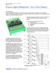
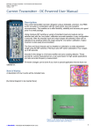
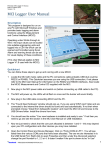
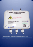
Peak/Valley Hold Unit (PVHU) User Manual V3.00 Part Number: DO-UM0084/30/UE Reference: Peak_Valley Hold Unit (PVHU) User Manual.docx Date: 30 May 2016 Version: 3.00 Applies to Firmware Version: V3.01 Peak/Valley Hold Unit (PVHU) User Manual Contents General Description .............................................................................................................. 3 Applications .......................................................................................................................... 3 Functional Diagram ............................................................................................................... 4 Example Operation ............................................................................................................... 4 Typical Operation .................................................................................................................. 5 Application Example ............................................................................................................. 6 Oscilloscope Pictures ........................................................................................................... 7 Connections .......................................................................................................................... 8 DIP SW1 Run/Operational Settings ...................................................................................... 9 Configuration Mode ............................................................................................................ 10 Resetting to Factory Defaults.............................................................................................. 11 Trimming of Outputs - Zero and Span Adjustment .............................................................. 11 Input Range Selection ........................................................................................................ 11 Output Range Selection ...................................................................................................... 12 Analogue Input Setup ......................................................................................................... 12 Input LED Setup ................................................................................................................. 12 Analogue Output Setup....................................................................................................... 12 Digital Output Setup ............................................................................................................ 12 Specifications...................................................................................................................... 13 User Manual ....................................................................................................................... 14 Filename: Peak_Valley Hold Unit (PVHU) User Manual.docx danntech © – PROCESS INSTRUMENTATION 2016 Date: 30 May 2016 Version: 3.00 Page 2 of 14 General Description The Peak/Valley Hold Unit (PVHU) has been designed to provide a way of capturing fast, random or transient events for process measurement and control. Usually only high speed and expensive process systems or PLCs are able to monitor and capture these inputs. The PVHU has one input and two outputs which can be used to capture the maximum (peak) and minimum (valley) values of the input signal. The PVHU captures the maximum and minimum values and holds these values until either another maximum or minimum value is detected, or the RESET TIME expires. The Reset Time can be adjusted from 0% to 100% (using a trimpot) in three ranges: 4 to 100 mS, 4 to 1000 mS and 4 mS to 10 S. There is an additional option to hold the peak and valley outputs until an external digital input resets the captured values. The PVHU has four way galvanic isolation of 1000 VDC between the Power In, the input and each output. The outputs are isolated from each other. A variety of standard signal inputs and outputs can be accommodated: Current (DC): 4-20 mA, 0-20 mA, (factory installed options are 0-1 A, 0-5 A and 0-10 A). Loop power available at +15 V, 22 mA for loop powered transmitter inputs. Voltage (DC): 0-100 mV, 0-1 V, 0-2 V, 0-10 V, 0-30 V, 0-100 V and ±10 V. Resistance: 0-100 Ω, 0-1 kΩ, 0-10 kΩ. There is also an option to be able provide 15 V at 30 mA to supply power for a loop powered input sensor or transmitter. The outputs can be different from each other and also different to the input, so the unit can effectively perform signal conversion and isolation functions as well. Special input and output ranges can be provided by arrangement. The unit has two analogue outputs with various options: Current (DC): 4-20 mA, 0-20 mA. Voltage (DC): 0-100 mV, 0-1 V, 0-10 V, ±10 V. As well as some digital I/O options: Relay Outputs - optional: Two alarm relay outputs 30 VDC at 1 A / 125 VAC, 0.3 A. Digital Outputs - optional: Two opto-isolated transistor outputs up to 50 V at 40 mA maximum. Digital Inputs - optional: Two opto-isolated digital inputs 30 V maximum at 5 mA. Applications Fast pulse stretching so that transient events can be captured by standard (slower) controllers or PLCs. Accelerometer peak level capture for machine condition monitoring. Hydroelectric turbine generator pole temperature estimation (see application note). Monitoring of rotor alignment in rotating machines using valley detection. Filename: Peak_Valley Hold Unit (PVHU) User Manual.docx danntech © – PROCESS INSTRUMENTATION 2016 Date: 30 May 2016 Version: 3.00 Page 3 of 14 Functional Diagram Example Operation These oscilloscope traces show the input signal in yellow with the Peak Output in blue and the Valley output in purple. This shown is an example of the outputs one can expect for a fairly high frequency input signal with a fairly short reset time, in this case approximately 20 mS. Filename: Peak_Valley Hold Unit (PVHU) User Manual.docx danntech © – PROCESS INSTRUMENTATION 2016 Date: 30 May 2016 Version: 3.00 Page 4 of 14 Typical Operation Filename: Peak_Valley Hold Unit (PVHU) User Manual.docx danntech © – PROCESS INSTRUMENTATION 2016 Date: 30 May 2016 Version: 3.00 Page 5 of 14 Application Example Simulated input signal constructed from data captured on site by the customer and sent to us for testing. Yellow trace is the simulated input signal, the blue trace is the Peak Output and the purple trace is the Valley Output. The Reset Time in this example is about 20 mS. The same results as above with the traces separated to show more detail. Filename: Peak_Valley Hold Unit (PVHU) User Manual.docx danntech © – PROCESS INSTRUMENTATION 2016 Date: 30 May 2016 Version: 3.00 Page 6 of 14 Oscilloscope Pictures Capturing a single pulse which is 200 µS duration. Peak and Valley Outputs for sine wave input. Repetitive peak and valley capturing. Filename: Peak_Valley Hold Unit (PVHU) User Manual.docx danntech © – PROCESS INSTRUMENTATION 2016 Date: 30 May 2016 Version: 3.00 Page 7 of 14 Connections More information to follow. Filename: Peak_Valley Hold Unit (PVHU) User Manual.docx danntech © – PROCESS INSTRUMENTATION 2016 Date: 30 May 2016 Version: 3.00 Page 8 of 14 DIP SW1 Run/Operational Settings Table 1 Dip Switch SW1 Settings in Run Mode – coloured background indicates settings as shipped. SW1 1 2 3 4 Default Setting Description Zero, Span and Reset Time Trimpots Enable Enables the operation of the trimpots on the front panel. You can enable the trimpots, make your adjustments and then when you disable the trimpots, the values that you last adjusted are saved and used until the trimpots are enabled again. OFF = trimpots disabled ON = trimpots enabled Zero and Span Normal/Wide Range Adjustment Select Provides “normal” and “wide” trimpot adjustments for Zero and Span. OFF = Zero and Span adjustment are normal i.e. approx ±10% over full trimpot range. ON = Zero and Span adjustment are “wide” i.e. approx ±50% over trimpot range. Note that you may need to adjust zero and span several times to get the best accuracy. Filtering Select Selects the moving average input filter length: Input Step Response SW1-3 SW1-4 Time No filtering – input OFF OFF response approx 0.2 mSec OFF ON 1 mSec ON OFF 10 mSec ON ON 100 mSec ON OFF OFF OFF Reset Range Select Value set using RESET trimpot on the front of the unit. 5 6 7 8 SW1-5 SW1-6 Reset Time Range OFF OFF 4 to 100 mSec OFF ON 4 mSec to 1 Sec ON OFF 4 mSec to 10 Sec Only reset using Digital ON ON Inputs Relays/Opto Outputs Enable (this feature not implemented yet) OFF = Relays/Opto Outputs Disabled ON = Relays/Opto Outputs Enabled Run or Configuration Mode Select OFF = Run ON = Configuration Filename: Peak_Valley Hold Unit (PVHU) User Manual.docx danntech © – PROCESS INSTRUMENTATION 2016 Date: 30 May 2016 OFF OFF OFF OFF Version: 3.00 Page 9 of 14 Configuration Mode When SW1-8 is ON then the configuration mode is activated. Only the relevant DIP switches may be used, i.e. only one switch between SW1-7 and SW1-2 (SW1-8 needs to be on to be in this mode and SW1-1 selects how to do the configurations using the analogue input or the trimpots). Table 2 Configuration Mode DIP Switch SW1 settings. SW1 Default Setting Description This DIP switch performs two functions depending upon what is being configured: Input or Trimpot Selection for Output Calibration i.e. SW1-6 or SW1-7 is ON. OFF = Analogue Input is used to excite the output ON = The trimpots are used to excite the output, Zero Trimpot for minimum and Span Trimpot for the maximum. 1 3 Digital Output Sense Select for Digital Output Setup i.e. SW1-3 is ON. This switch setting at the time of capturing the Digital Output Setpoint selects whether the respective Digital Output is active when the input goes from low to high (for a Peak) , or from high to low (for a Valley). OFF = Low to High ON = High to Low Test Mode Repeated pressing of the push button sets the following on both outputs, repeated pressing restarts the cycle: Push Button Press Number Outputs follow the input as per normal 0 operation Outputs at absolute minimum (DAC 1 output=0) 2 Outputs at 0% 3 Outputs at 50% 4 Outputs at 100% Outputs at absolute maximum (DAC 5 output=4095) Digital Output Setup 4 Input LED Setup 5 Input Calibrate 6 Output 1 Calibrate 7 Output 2 Calibrate 8 Run or Configuration Mode Select OFF = Run ON = Configuration 2 Filename: Peak_Valley Hold Unit (PVHU) User Manual.docx danntech © – PROCESS INSTRUMENTATION 2016 OFF Date: 30 May 2016 Version: 3.00 Page 10 of 14 Resetting to Factory Defaults Sometimes this is necessary if one gets things confused. To do this, switch all SW1 switches ON except SW1-8, then press the PB for >2 seconds. The factory defaults areas shown in the Table 2 Configuration Mode DIP Switch SW1 settings. [not yet implemented in V3.01] Trimming of Outputs ‐ Zero and Span Adjustment If the Zero and Span Trimpot are enabled (i.e. SW1-1 is ON in the RUN Mode) the outputs Zero and Span can be trimmed. Can only be done in the Run Mode. This is done by pressing and holding the Push Button (PB) for one second or more until the A2 LED first comes on and then shortly after, the A1 LED illuminates, this then sets the unit into the Output Trim mode. (if SW1-1 is OFF nothing will happen). The Peak LED will be on. Now you can trim the Peak Output Zero and Span using the trimpots. If you wish to move to the Valley Output without changing the Peak Output just press the PB briefly, this moves on to the next output without capturing the trimpot adjustments. If you wish to adjust the zero and span and capture the new values, press the PB for about 1 second until A2 comes on and then release, this will capture the new trimpot values for the Peak Output and move on to the Valley Output. Repeat until both the outputs are done. When the Valley Output is done the unit goes back into the Run mode. Input Range Selection DIP Switch SW1 # Input 1/A 2/B 3/C 4/D 5/E 6/F 7/G 8/H 4-20mA OFF ON ON OFF OFF OFF OFF ON 0-20mA OFF ON ON OFF OFF OFF OFF ON 0-100mV OFF OFF OFF OFF OFF ON OFF OFF 0-1V OFF OFF OFF OFF OFF ON ON OFF 0-10V OFF ON OFF ON OFF ON OFF OFF 0-30V (J3 in R2=620Ω) OFF ON OFF OFF OFF ON OFF OFF 0-100V OFF OFF ON OFF OFF ON ON OFF ±10V OFF ON OFF OFF ON ON ON OFF 0-2V (J3 in R2=1.1kΩ) OFF ON OFF OFF OFF ON OFF OFF Filename: Peak_Valley Hold Unit (PVHU) User Manual.docx danntech © – PROCESS INSTRUMENTATION 2016 Date: 30 May 2016 Version: 3.00 Page 11 of 14 For self-powered mA input (normal operation) – J1=A, J2=A For loop powered mA input (with fused +15 V supply) – J1=B; J2=B Output Range Selection Information to follow. Analogue Input Setup Information to follow. Input LED Setup Information to follow. Analogue Output Setup Information to follow. Digital Output Setup Information to follow. Filename: Peak_Valley Hold Unit (PVHU) User Manual.docx danntech © – PROCESS INSTRUMENTATION 2016 Date: 30 May 2016 Version: 3.00 Page 12 of 14 Specifications One analogue input, two isolated analogue outputs one for Peak (maximum) value and the other for Valley (minimum) value. Input and each output can be configured differently if required. For example the input can be 010 V, the Peak output can be 4–20 mA and the Valley output could be ±5 V. Galvanic isolation between input, power supply and each output > 1000 VDC. DC supply required – 12 or 24 VDC, -5%, +10% at 100 mA max. Typical step response time (input to output) - less than 0.2 mS. Split rail powered input circuit to accommodate input signals from ±100 V down to ±100 mV or ±100 mA down to ±100 µA. Standard process signal inputs available, 0-10 V, 0-5 V, 0-2 V, ±10 V, 0-20 mA, 4-20 mA. Also factory configured currents 0 – 1 A, 0 – 5 A, 0 – 10 A AC or DC. Input impedance standard for voltage inputs at 100 kΩ but can be arranged to be 1 MΩ if required. Input impedance is 50 Ω for mA current inputs. DC coupled input signal as standard but can be arranged to be AC coupled if required. Analogue input resolution 0.1% of input range. Input sampling and processing frequency approximately 10 kHz (100 µS). Minimum input pulse width for reliable detection – 0.2 mS. Split rail powered output circuit - output signals from ±12 V down to ±100 mV. Output current for voltage output option at 5 mA. Output current range for current output option from 0 to 22 mA. Analogue output resolution 0.05% of range. Overall accuracy better than 1% of range. Output trimpot zero and span adjustments for each output on front panel. Reset time adjustable using trimpot beneath front panel from 0 to 100% of the selected range. Operating temperature -10°C to +70°C. Power On/Status green LED. Plug-in screw terminals which can accommodate wire up to 2.0 mm2. DIN rail mounting enclosure - 22.5 x 100 x 113 mm (width x length top to bottom x height off DIN rail). Approximate weight 100 g. Filename: Peak_Valley Hold Unit (PVHU) User Manual.docx danntech © – PROCESS INSTRUMENTATION 2016 Date: 30 May 2016 Version: 3.00 Page 13 of 14 User Manual The latest version of this User Manual can be found at: http://www.danntech.com/user%20manuals/Peak_Valley%20Hold%20Unit%20(PVHU)%20User Manual.pdf or by scanning in: danntech Ltd Co. No. 6510211 15 College Close, Hamble-le-Rice Southampton, Hampshire SO31 4QU United Kingdom Tel: 075 9069 1824 e-mail: [email protected] www.uk.danntech.com www.danntech.com danntech cc Reg. No. CK1986/15338/23 Tel International: +27 11 7921239 Tel National: 011 7921239 Fax International: +27 11 7924687 Fax National: 011 7924687 e-mail: [email protected] P O Box 1023, Fontainebleau, 2032 Republic of South Africa www.danntech.co.za www.danntech.com Danntech makes no warranty of any kind with regard to this material, including, but not limited to, the implied warranties of merchantability and fitness for a particular purpose. Danntech shall not be liable for errors contained herein or for incidental or consequential damages in connection with the furnishing, performance or use of this material. This document contains proprietary information, which is protected by copyright. No part of this document may be photocopied, reproduced, or translated into another language without the prior written consent of Danntech. The information in this document is subject to change without notice. Filename: Peak_Valley Hold Unit (PVHU) User Manual.docx danntech © – PROCESS INSTRUMENTATION 2016 Date: 30 May 2016 Version: 3.00 Page 14 of 14