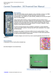
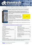
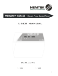
1
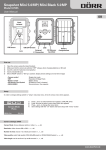
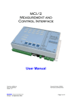
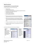
3InputVoltage_CurrentTransmitterUserManual
V1.01–21stOctober2014
©danntech 2014
www.danntech.com
3InputVoltage/CurrentTransmitterUserManual
The 3 Input Voltage/Current Transmitter
has been designed using three powerful
microprocessors which enable us to do
true RMS to DC conversion and digital
signal isolation. We are able to offer
flexibility, reliability and accuracy at an
economical price in an industrial package
for safe operation up to 600 VAC.
Voltage measurement can be DC or AC
(true RMS) up to 600 V and current
inputs DC or AC (true RMS) up to 15 A.
A millivolt input option can be used for
external current shunts. The device
provides an accuracy of better than 0.5%
with isolated current or voltage outputs
using 12 or 24 VDC nominal supplies.
Each input and each output can be
configured differently and they need not
all be the same.
If you have any comments or suggestions which could improve this User Manual please e-mail them to me at
mailto:[email protected]?subject=3 Input Voltage_Transmitter User Manual - Comment.
Filename: 3 Input Voltage_Current Transmitter User Manual.docx
Version: 1.01
©
danntech
– PROCESS INSTRUMENTATION
21 October 2014
Page 1 of 15
Contents
Contents ............................................................................................................................................... 2 General Description ............................................................................................................................. 3 Functional Diagram .............................................................................................................................. 3 Connections ......................................................................................................................................... 4 Inputs: ........................................................................................................................................... 4 Outputs: ........................................................................................................................................ 4 Auxiliary Power: ............................................................................................................................ 5 Input Range Selection .......................................................................................................................... 5 Using the Push-In PCB Terminals........................................................................................................ 7 Input and Output Setup ........................................................................................................................ 8 Input Setup ........................................................................................................................................... 9 Steps to follow to calibrate the inputs: ........................................................................................... 9 Output Range Selection ..................................................................................................................... 10 Output Setup ...................................................................................................................................... 10 Steps to follow to calibrate the outputs: ...................................................................................... 10 Connection Example .......................................................................................................................... 11 Typical Test Results ........................................................................................................................... 11 Application Examples ......................................................................................................................... 12 Input using a Loop Powered Sensor Input ......................................................................................... 13 Future Options ................................................................................................................................... 13 Specifications ..................................................................................................................................... 13 Part Numbering .................................................................................................................................. 14 Inputs and Outputs the Same: ........................................................................................................ 14 Inputs and Outputs Different: .......................................................................................................... 15 User Manual Updates ........................................................................................................................ 15 Filename: 3 Input Voltage_Current Transmitter User Manual.docx
Version: 1.01
©
danntech
– PROCESS INSTRUMENTATION
21 October 2014
Page 2 of 15
GeneralDescription
This 3IVCT is based on a combination of our new True RMS Voltage/Current Transmitter, the Quad
Signal Processor and the Eight Analogue Input Module (AIM-8). This has been adapted initially for
applications where an application requires three similar isolated measurements for a PLC, data
logger or controller. The design allows us to operate at up to 600 V (AC or DC) with a protected
enclosure and to be able to take advantage of the common 0V output to reduce the cost compared to
three separate converters/transmitters.
FunctionalDiagram
Filename: 3 Input Voltage_Current Transmitter User Manual.docx
Version: 1.01
©
danntech
– PROCESS INSTRUMENTATION
21 October 2014
Page 3 of 15
Connections
Inputs:
Terminal
Number
1
2
3
Description
Circuit Label
Voltage Input 1
Current Input 1
Common 1
Vin #1
Iin #1
0 Vin #1
Input #2
CN2
4
5
6
Voltage Input 2
Current Input 2
Common 2
Vin #2
Iin #2
0 Vin #2
Input #3
CN3
7
8
9
Voltage Input 3
Current Input 3
Common 3
Vin #3
Iin #3
0 Vin #3
Description
Circuit Label
Output #1
Output #2
Output #3
Output
Common
Out 1
Out 2
Out 3
Input #1
CN1
Outputs:
CN4
Terminal
Number
11
12
13
10
Filename: 3 Input Voltage_Current Transmitter User Manual.docx
Version: 1.01
©
danntech
– PROCESS INSTRUMENTATION
0Vo
21 October 2014
Page 4 of 15
AuxiliaryPower:
CN11
Terminal
Description
Number
14
Power In 15
Power In +
Circuit Label
0Vps
+Vps
InputRangeSelection
Filename: 3 Input Voltage_Current Transmitter User Manual.docx
Version: 1.01
©
danntech
– PROCESS INSTRUMENTATION
21 October 2014
Page 5 of 15
0 to 5 A input (AC or DC current) –
0R025 shunt installed. J4, J2, J3 and J5 – don’t care.
Input terminals - Iin and 0Vin.
Additional current ranges change current shunt resistor to suit - need about 125 mV or less.
Input 1
Input 2
Input 3
SW1
SW2
SW3
1(A)
OFF
SW1
SW2
SW3
2(B)
ON
SW1
SW2
SW3
3(C)
OFF
SW1
SW2
SW3
4(D)
OFF
SW1
SW2
SW3
5(E)
ON
0 to 125 mV (shunt input AC or DC mV) –
J4, J2, J3 and J5 installed.
Input terminals - Vin and 0Vin.
Input 1
Input 2
Input 3
SW1
SW2
SW3
1(A)
OFF
SW1
SW2
SW3
2(B)
ON
SW1
SW2
SW3
3(C)
OFF
SW1
SW2
SW3
4(D)
OFF
SW1
SW2
SW3
5(E)
ON
0/4-20 mA input (process signal input) –
J4, J2, J3 and J5 installed.
Input terminals - Vin and 0Vin (NOTE !)
Input 1
Input 2
Input 3
SW1
SW2
SW3
1(A)
ON
SW1
SW2
SW3
2(B)
OFF
SW1
SW2
SW3
3(C)
OFF
SW1
SW2
SW3
4(D)
ON
SW1
SW2
SW3
5(E)
OFF
Filename: 3 Input Voltage_Current Transmitter User Manual.docx
Version: 1.01
©
danntech
– PROCESS INSTRUMENTATION
21 October 2014
Page 6 of 15
0-10 V input (process signal input) –
Install J2, J3 and J4 - leave J4 OPEN.
Input terminals Vin and 0Vin.
Input 1
Input 2
Input 3
SW1
SW2
SW3
1(A)
OFF
SW1
SW2
SW3
2(B)
OFF
SW1
SW2
SW3
3(C)
OFF
SW1
SW2
SW3
4(D)
OFF
SW1
SW2
SW3
5(E)
OFF
0-600 V, 0-400 V, 0-250 V, 0-150 V (AC or DC voltage) Input terminals Vin and 0Vin.
Input 1
Input 2
Input 3
SW1
SW2
SW3
1(A)
OFF
SW1
SW2
SW3
2(B)
OFF
SW1
SW2
SW3
3(C)
ON
SW1
SW2
SW3
4(D)
OFF
SW1
SW2
SW3
5(E)
OFF
Input 1
Input 2
Input 3
0-600 V
0-400 V
0-250 V
0-150 V
J4
J14
J24
Open
Closed
Closed
Closed
J2
J12
J22
Open
Open
Closed
Closed
J3
J13
J23
Open
Open
Open
Closed
J5
J15
J25
Open
Open
Open
Open
UsingthePush‐InPCBTerminals
We have used push-in terminals so that it is easy to connect reliably with cables and wires which
have been terminated using ferrules that can be fed through the gland in the bottom of the enclosure.
Filename: 3 Input Voltage_Current Transmitter User Manual.docx
Version: 1.01
©
danntech
– PROCESS INSTRUMENTATION
21 October 2014
Page 7 of 15
InputandOutputSetup
Switches 6, 7 and 8 of DIP switches SW1, SW2 and SW3 are used to calibrate the inputs and
outputs. Having setup the input range that you plan to use you now need to capture the Reference
Input Minimum (RIM) and the Input Maximum (IM). After doing that, you then range the output by
varying the input and then capturing the desired output minimum and maximum.
Normally we would set up the inputs and outputs for you prior to delivery but you can do this
procedure yourself if necessary.
Filename: 3 Input Voltage_Current Transmitter User Manual.docx
Version: 1.01
©
danntech
– PROCESS INSTRUMENTATION
21 October 2014
Page 8 of 15
InputSetup
To calibrate an input you will require a current or voltage source capable of covering the range you
plan to use. So in the case of 0 – 600 VAC you will need an AC voltage source which you can adjust
over this full range. It should be stable and you should be able to use a voltmeter to display the input
voltage – RMS AC.
(We have included a test input which can be used to inject much lower voltages to simulate the
various voltage and current inputs. This is not the best way to get the most accurate input calibration
but is useful to configure the outputs and if you don’t have the correct voltage source available. A
table of the conversions for each range and the test voltage inputs will be included here in due
course. Please contact us if you wish to use this before these details are published.)
Stepstofollowtocalibratetheinputs:
1.
Select the input range you plan to use and the filter value you wish.
2.
Connect up your input source with meter for display of the input value to the input to be
calibrated.
3.
Set switch 8 to ON and switch 7 OFF to select input calibration. You will see the green
configuration indicator LED flashes slowly to indicate that you are going to capture the
Reference Input Minimum.
4.
Remove the link located on the Capture Link (J8, J18 or J29=8) so that you can short out the
Capture Link to record the value of the input as the RIM value.
5.
Inject 20% of the input range (this is the Reference Input Minimum – we use the 20% value to
avoid noise and inaccuracy at 0% input) [for 0-600 VAC input range this will be 120 VAC].
6.
Then close (short) the Capture Link for about 1 second or so, until the Red Configuration
Indicator LED lights up, then open the link. This indicates that the value has been captured.
7.
The Green Configuration Indicator LED will now flash faster to indicate that you are going to
capture the Input Maximum.
8.
Inject 100% of the input range (this is the Input Maximum) [for 0-600 VAC input range this will
be 600 VAC].
9.
Close (short) the Capture Link for about 1 second or so, until the Red Configuration Indicator
LED lights up, then open the link. This indicates that the value has been captured.
10. This completes the input calibration – switch 8 OFF to complete the process or move on to the
output calibration for this input (see the next section).
Filename: 3 Input Voltage_Current Transmitter User Manual.docx
Version: 1.01
©
danntech
– PROCESS INSTRUMENTATION
21 October 2014
Page 9 of 15
OutputRangeSelection
You can select various output using the three four-way DIP switches and firmware control.
Output 1
Output 2
Output 3
DIP switch SW4
DIP switch SW5
DIP switch SW6
DIP
Switches
SW4 – SW6
Output
1 (A)
2 (B)
3 (C)
4 (D)
4-20mA
ON
OFF
ON
OFF
0-20mA
ON
OFF
ON
OFF
0-10V
OFF
ON
OFF
OFF
±10V
OFF
ON
ON
ON
OutputSetup
Stepstofollowtocalibratetheoutputs:
1.
Select the output range you plan to use SW4 for Output #1, SW5 for Output #2 and SW6 for
Output #3.
2.
Connect up your with meter to the output for display of the output value.
3.
Set switch 8 to ON and switch 7 ON to select output calibration. You will see the green
configuration indicator LED flashes slowly to indicate that you are going to capture the Output
Minimum.
4.
Remove the link located on the Capture Link (J8, J18 or J29=8) so that you can short out the
Capture Link to record the value of the output as the Output Minimum Value.
5.
Now you should use the input source and adjust the input which will cause the output to follow.
When you have the output at the minimum output value that you wish proceed to the next step.
6.
Close (short) the Capture Link for about 1 second or so, until the Red Configuration Indicator
LED lights up, then open the link. This indicates that the output value has been captured as the
minimum.
7.
The Green Configuration Indicator LED will now flash faster to indicate that you are going to
capture the Output Maximum.
Filename: 3 Input Voltage_Current Transmitter User Manual.docx
Version: 1.01
©
danntech
– PROCESS INSTRUMENTATION
21 October 2014
Page 10 of 15
8.
Again adjust the input until the output reaches the desired Output Maximum Value.
9.
Close (short) the Capture Link for about 1 second or so, until the Red Configuration Indicator
LED lights up, then open the link. This indicates that the Output Maximum Value has been
captured.
10. This completes the output calibration – switch 7 and 8 OFF to complete the process. ConnectionExample
Typical connections for Inputs: 3 x 600 VAC; Outputs: 3 x 4-20 mA; Aux. Supply: 12 VDC
TypicalTestResults
Filename: 3 Input Voltage_Current Transmitter User Manual.docx
Version: 1.01
©
danntech
– PROCESS INSTRUMENTATION
21 October 2014
Page 11 of 15
ApplicationExamples
Motor Voltage Monitoring
Three Phase Rectifier Monitoring
Filename: 3 Input Voltage_Current Transmitter User Manual.docx
Version: 1.01
©
danntech
– PROCESS INSTRUMENTATION
21 October 2014
Page 12 of 15
InputusingaLoopPoweredSensorInput
Information to follow.
FutureOptions
We have made provision for the addition of a RS485 Modbus Interface and we will be able to add a
digital display of each input with relay output alarm functions.
Specifications
Inputs:
Three separate, isolated inputs, AC voltage and AC current (can also be DC Voltage or
DC Current).
0 to 600 VAC in several ranges: 0-600, 0-400, 0-250, 0-150 VAC (link configurable).
0 to 15 A AC in four ranges: 0-1, 0-5 A AC (link configurable) and 0-10, 0-15 A AC
(factory configurable by changing shunt resistors).
True RMS AC conversion.
Input frequency measurement response range 0 to 500 Hz.
12 bit input conversion for AC, 16 bit input conversion for DC.
Dedicated processor for each input to do true RMS to DC conversion, signal
conditioning and digital signal isolation.
Outputs:
3 outputs sharing a common 0 V – primarily designed for PLC or other controller type
inputs.
0-20 mA, 4-20 mA, 0-10 V, 0-5 V, ±10 V (DIP switch selectable).
Output response time approximately 1 second or less.
12 bit output conversion.
Aux Power: 12 VDC +10%, -5% at approximately 500 mA maximum, 24 VDC +10%, -5% at
approximately 300 mA maximum or optional wide range input 9 to 36 VDC.
Connection: Bottom entry cable glands for high voltage inputs suitable for cable diameters 4 to
10 mm with PCB mounted push-in power terminals. One output and one power cable
glands for cable diameters 2.5 to 6.5 mm at the top of the enclosure.
Enclosure:
IP66 ABS enclosure, chassis mounting, dimensions (including cable glands) 160 x 170
x 90 mm (width x height x depth). Mounting footprint drill centres 100 x 140 mm.
Packaged size: 260 x 195 x 115 mm (L x W x H) – weight 0.6 kg.
Filename: 3 Input Voltage_Current Transmitter User Manual.docx
Version: 1.01
©
danntech
– PROCESS INSTRUMENTATION
21 October 2014
Page 13 of 15
PartNumbering
InputsandOutputstheSame:
Part Numbering for Units where all three inputs and the three outputs are setup to be the same. For
example Input = 3 x 600 VAC, Output = 3 x 4-20 mA. Part numbering for units with different inputs
and outputs see the next section.
P3I-axy-nt/p
Input configuration letters: axy
a = A for AC input
a = D for DC input
x = V for voltage input
x= I for current input
y = range
The ranges provide several options in three sections AC and DC voltage and current for AC and DC:
y values for AC and
DC Voltage Input
A = 0 - 10 V
B = 0 - 50 mV
C = 0 - 100 mV
D = 0 - 5 V AC
E = 0 – 250 V
F=1-5V
G = 0 – 150 V
H = 0 – 300 V
I=
K=0-1V
L = 0 - 20 V
M = 0 - 110 V
N = 0 - 220 V
P = 0 - 240 V
Q = 0 - 400 V
R = 0 - 115 V
S = 0 - 250 mV
T = 0 – 600 V
U = 0 - 200 mV
V = 0 - 250 V
W = 0 - 500 V
X = 0 – 30 mV
Y = 0 - 200V AC
Z = 0 – 60 mV
AC = 0-24 V
y values for AC Current Input
Output configuration letters: nt
noutput signal type : I = current
toutput signal range
M = 0 - 1 A AC RMS
N = 0 - 5 A AC RMS
P = 0 - 10 A AC RMS
Q = 0 – 15 A AC RMS
S = 0 – 20 mA AC RMS
(for clamp-on sensor 075A)
T = 0 – 4 mA AC RMS
(for clamp-on sensor 016A)
y values for DC
Current Input
A = 4 ‐ 20 mA B = 0 ‐ 20 mA C = "5.5 mA D = 0 ‐ 1 mA E = 0 ‐ 5 mA F = 0 ‐ 50 mA G = "5.0 mA H = "150 mA J = 0 – 60 mA K = 0 – 10 mA L = 0 ‐ 200 mA M = 0 ‐ 1 A N = 0 ‐ 5 A P = 0 ‐ 10 A Q = 0 – 15 A V = voltage
current (n=I):
A = 4 - 20 mA
B = 0 - 20 mA
D = 0 - 1 mA
E = 0 - 5 mA
Filename: 3 Input Voltage_Current Transmitter User Manual.docx
Version: 1.01
©
danntech
– PROCESS INSTRUMENTATION
21 October 2014
Page 14 of 15
F = 20 - 4 mA
voltage (n=V):
A = 0 - 10 V
D=0-5V
E = ±5 V
F=1-5V
G = ±10 V
K=0-1V
Auxiliary power supply:
pC = 24 VDC,
D = 12 VDC
E = 9 - 18 VDC
G = 18 – 36 VDC
H = 36 – 72 VDC
(nominally 12 VDC)
(nominally 24 VDC)
(nominally 48 VDC)
We also have planned mains powered versions:
pAB = 90 to 260 VAC
InputsandOutputsDifferent:
In the cases where there is a mixture of input and output requirements, we use a serialized
numbering system to cater for the very many permutations possible. We will allocate a unique
configuration number for each configuration.
P3I-Mxxxxx/p
xxxxx - configuration number starting at 00001
p – auxiliary power supply as above
UserManualUpdates
Please use the QR code to get the latest version of this User Manual.
http://danntech.com/user%20manuals/3%20Input%20Voltage_Current%20Transmitter%20User%20Manual.pdf
danntech Ltd
danntech cc
Co. No. 6510211
15 College Close, Hamble-le-Rice
Southampton, Hampshire
SO31 4QU
United Kingdom
Tel: 075 9069 1824
Reg. No. CK1986/15338/23
P O Box 1023, Fontainebleau
Randburg, 2032. SA
Tel: +27 (0) 11 7921239
Fax: +27 (0) 11 7924687
e-mail: [email protected]
e-mail: [email protected]
www.danntech.com
www.uk.danntech.com
P O Box 1023, Fontainebleau, 2032
Republic of South Africa
www.danntech.co.za
www.danntech.com
Danntech makes no warranty of any kind with regard to this material, including, but not limited to, the implied warranties of merchantability and fitness for a particular purpose.
Danntech shall not be liable for errors contained herein or for incidental or consequential damages in connection with the furnishing, performance or use of this material. This
document contains proprietary information, which is protected by copyright. No part of this document may be photocopied, reproduced, or translated into another language
without the prior written consent of Danntech. The information in this document is subject to change without notice.
Filename: 3 Input Voltage_Current Transmitter User Manual.docx
Version: 1.01
©
danntech
– PROCESS INSTRUMENTATION
21 October 2014
Page 15 of 15