1
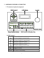
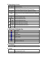
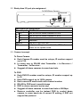
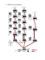
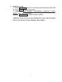
USER MANUAL
MULTI-FUNCTION
REMOTE-CONTROLLER
WARNINGS, CAUTIONS & COPYRIGHT
WARINGS
TO REDUCE THE RISK OF FIRE OR ELECTRIC SHOCK, DO NOT EXPOSE THIS PRODUCT TO RAIN OR
MISTURE.
DO NOT INSERT ANY METALLIC OBJECT THROUGH VENTILATION GRILLS.
CAUTION
CAUTION
RISK OF ELECTRIC SHOCK
DO NOT OPEN
CAUTION: TO REDUCE THE RISK OF ELECTRIC SHOCK.
DO NOT REMOVE COVER (OR BACK).
NO USER-SERVICEABLE PARTS INSIDE.
REFER SERVICING TO QUALIFIED SERVICE PERSONNEL.
Explanation of Graphical Symbols
The lightning flash with arrowhead symbol, within an equilateral triangle, is intended to alert
the user to the presence of insinuated "dangerous voltage" within the products enclosure
that may be of sufficient magnitude to constitute a risk of electric shock to persons.
The exclamation point within an equilateral rhombus is intended to alert the user to the
presence of important operating and maintenance (servicing) instruction in the literature
accompanying the product.
USERS OF THE SYSTEM ARE RESPONSIBLE FOR CHECKING AND COMPLYING WITH ALL FEDERAL,
STATE, AND LOCAL LAWS AND STATUTES COIPCERNING THE MONITORING AND RECORDING OF
VIDEO AND AUDIO SIGNALS. ULTRAK SHALL NOT BE HELD RESPONSIBLE FOR THE USE OF THIS
SYSTEM IN VIOLATION OF CURRENT LAWS AND STATUTES.
COPYRIGHT
THE TRADEMARKS MENTIONED IN THE MANUAL ARE LEGALLY REGISTERED TO THEIR
RESPECTIVE COMPANIES.
ii
INDEX
1
INTRODUCTION
1
2
SPECIFICATION
1
3
HARDWARE OVERVIEW & CONNECTING
2
3-1
Front plane keyboard assignment
2
3-2
Back plane I/O port pin assignment
4
3-3
Connect concept
4
3-4
RS-485 Connecting Diagram
5
Dome Camera setup & operation
6
4-1
Setup Dome camera
6
4-2
Setup Dome camera ID
6
4-3
Setup preset point / DWELL / SPEED
6
4-4
Move to preset point
6
4-5
Auto Pan Mode (By Dome Camera)
6
4-6
Auto SEQ Mode (By Dome Camera)
6
4-7
Change Dome Camera ID and control
6
DVR setup & operation
7
5-1
Setup DVR model & ID
7
5-2
Setup DVR ID
7
5-3
Setup Dome Camera after DVR
7
5-4
Change DVR ID and control
7
5-5
Setup preset point / DWELL / SPEED
7
5-6
Move to preset point
7
5-7
Auto Pan Mode (By Dome Camera)
7
5-8
Auto SEQ Mode (By Dome Camera)
7
ISP Update
8
ISP Firmware Update
8
4
5
6
6-1
V 1.00
iii
26/JUN/2006
1 INTRODUCTION
This MULTI-FUNCTION REMOTE-CONTROLLER with following features:
z Control Dome Camera \ DVR \ Dome Camera after DVR in the same
time.
z Support Dome Camera ID up to 128 & DVR ID up to 32.
z Support baud rate 2400 / 4800 / 9600.
z Dome Camera support following protocol / model:
PELCO-D
PELCO-P
z
z
z
DYNACOLOR D7
PIH-7X(LILIN)
DMP-15H1
DVR
08CH
16CH
04CH
REMOTE-CONTROLLER protocol upgradeable by RS-232 from PC.
Through-able controls the Dome Camera after DVR.
2 SPECIFICATION
In/Output
RS-485
Power
DC12V, 1A , 2 Watts
Consumption
320W*61H*166D mm (Not Include Joystick)
Dimensions
2D 1.4Kg / 3D 1.6Kg
Weight
Operation
5 to 45 ℃
Temp.
Storage
5 to 95% Non-condensation
Humidity
SPECIFICATIONS ARE SUBJECT TO CHANGE WITHOUT NOTICE
1
3 HARDWARE OVERVIEW & CONNECTING
3.1 Front plane keyboard assignment
LCD Module
DVR Control 1
Joystick
ENTER
AUTO
SEL
MENU
IN
1
2
3
4
5
6
7
8
OUT
9
10
11
12
13
14
15
16
Dome Camera Control
DVR Control 2 & Number Key
A. DVR Control 1
S
Setup mode: Change item or value.
DVR mode: Change to 9 camera formats.
W
Setup mode: Change item or value.
DVR mode: Change to 13 camera formats.
X
Setup mode: Change item or value.
DVR mode: Change to 16 camera formats.
T
Setup mode: Change item or value.
DVR mode: Change to 4 camera formats.
AUTO
SEL
Auto dwell mode in DVR mode.
Change DVR channel.
MENU
Into DVR menu.
ENTER
Enter menu or confirm setting.
2
B. Dome Camera Control
PRESET
Go to preset point.
SET PRESET Setup preset point.
MODE
Switch between DVR and Dome Camera mode.
DVR mode: Single channel full screen PTZ control.
AUTO PAN
Dome camera in auto tour mode. (Depend on camera)
OSD
Dome camera On Screen Display. (Depend on camera)
SEQ
Dome camera auto switch between preset points. (Depend on
camera)
CLR
Clear or Exit.
DEV
Devices ID address setting.
FOCUS
NEAR
Manually adjusted the focus.
FAR
Manually adjusted the focus.
IRIS
OPEN
Manually open the iris of the lens.
CLOSE Manually close the iris of the lens.
ZOOM
IN
OUT
Manually adjusted the zoom lens in.
Manually adjusted the zoom lens out.
C. DVR Control 2 & Number Key
Recording
Fast Rewind
Rewind
Field Rewind
Stop
Field Forward
Play
Fast Forward
1-16
10
Channel & number key
Equal to number 0
D. LCD Module
Monochrome
Matrix 4 line 20 font display
E. Joystick
2D
Linear control 2D joystick, adjust camera direction &
movement speed by pitch
3D
Support Z axis function for zoom in & out function.
3
3.2 Back plane I/O port pin assignment
To DVR/Dome Camera
Reserved
Firmware Upgrade
Power Input
RS-485
Back plane pin assignment
Power Input DC 12V 1A
Link to DVR or Dome Camera R+ or A.
T+
Link to DVR or Dome Camera R- or B.
TReserved
R+
Reserved
RLink to PC RS-232 Port.
RS-232
In System Programmer Hold the ISP bottom and
ISP
power on for update mode.
3.3 Connect concept
To Dome Camera
z Each Camera ID number must be unique, ID number support
up to 128.
z In series way to RS-485 data Transmitter + to Receiver+ /
Transmitter - to Receiver-.
z Suggest all dome cameras in same baud rate.
To DVR
z Each DVR ID number must be unique, ID number support up
to 32.
z Each DVR support up to 16CH camera
z Each camera ID must match with channel number.
z RS-485 to DVR must in parallel ways
z DVR to dome camera in series way.
z Suggest all dome cameras in same baud rate or 9600bps.
z Remove controller can be instead DVR to control dome
camera, in same baud rate & correct ID setting, if DVR not
support the protocol.
4
3.4 RS-485 Connecting Diagram
Up to 16CH
Up to 16CH
D+ D- D+ D-
0 1 0 1
Up to 128 ID
R+ R- T+ T-
R+ R- T+ T-
Dome Cam 4
CH 4
ID 4
Dome Cam 4
CH 4
ID 4
D0+ D0- D1+ D1-
A B A B
Dome Cam 3
CH 3
ID 3
Dome Cam 2
CH 2
ID 2
Dome Cam 3
CH 3
ID 3
0 1 0 1
Dome Cam 2
CH 2
ID 2
D0+ D0- D1+ D1-
Dome Cam 1
CH 1
ID 1
R+ R- T+ T-
Dome Cam 3
ID 3
Up to 128 ID
Dome Cam 1
CH 1
ID 1
A B A B
D+ D- D+ D-
Dome Cam 2
ID 2
D+ D- D+ D-
A B A B
DVR 1
ID 1
DVR 2
ID 2
Dome Cam 1
ID 1
Up to 32 ID
DATA+
DATA-
5
4 Dome Camera setup & operation
4.1 Setup Dome camera
4.1.1
Press MODE into MODE SETTING mode and MODE:XXXX
would flash on the screen.
4.1.2
By S or T to change DOME/BAUD.
4.1.3
By W or X to adjust value.
4.1.4
Press ENTER to save setting.
4.2 Setup Dome camera ID
4.2.1
Press DEV (DEVICE).
4.2.2
Key in ID number.
4.2.3
Press ENTER to save setting.
4.3 Setup preset point / DWELL / SPEED
4.3.1
Press SET PRESET
4.3.2
Key in preset point number.
4.3.3
Press SET PRESET
4.3.4
By joystick moving the lens to the place went to set.
4.3.5
Press 2 into DWELL & SPEED setup by S or T to change
item & W or X to adjust value.
4.3.6
Press SET PRESET or 1 to save setting
4.4 Move to preset point
4.4.1
Press PRESET key.
4.4.2
Enter Preset point number.
4.4.3
Press PRESET key.
4.5 Auto Pan Mode (By Dome Camera)
4.5.1
Press AUTO PAN Key.
4.5.2
Press 1 to start.
4.5.3
Or 2 to setting.
4.5.4
Or 3 exit AUTO PAN Mode.
4.6 Auto SEQ Mode (By Dome Camera)
4.6.1
Press SEQ Key.
4.6.2
Press 1 to start.
4.6.3
Or 2 to setting.
4.6.4
Or 3 exit SEQ Mode.
4.7 Change Dome Camera ID and control
4.7.1
Press DEV
4.7.2
Key in ID number.
4.7.3
Press DEV key to change ID.
6
5 DVR setup & operation
5.1 Setup DVR model & ID
5.1.1
Press MODE into MODE SETTING mode and DVR:DVR
CONTOLER would flash on the screen.
5.1.2
Press twice DEV (DEVICE) & SET DVR NUM:00 show up.
5.1.3
Key in ID number.
5.1.4
Press MODE & by W or X to select DVR model &
DVR:XXXXXXXXX would flash on the screen..
5.1.5
Press DEV (DEVICE) to save setting.
5.2 Setup DVR ID
5.2.1
Press DEV (DEVICE).
5.2.2
Key in ID number.
5.2.3
Press DEV or ENTER to save setting.
5.3 Setup Dome Camera after DVR
5.3.1
Press Channel into full screen mode.
5.3.2
Press MODE & by W or X to select protocol.
5.3.3
Press DEV to save setting.
5.4 Change DVR ID and control
5.4.1
Press DEV
5.4.2
Key in ID number.
5.4.3
Press DEV key to change ID.
5.5 Setup preset point / DWELL / SPEED
5.5.1
Press Channel into full screen mode.
5.5.2
Press SET PRESET
5.5.3
Key in preset point number.
5.5.4
Press SET PRESET
5.5.5
By joystick moving the lens to the place went to set.
5.5.6
Press 2 into DWELL & SPEED setup by S or T to change
item & W or X to adjust value.
5.5.7
Press SET PRESET or 1 to save setting
5.6 Move to preset point
5.6.1
Press Channel into full screen mode.
5.6.2
Press PRESET key.
5.6.3
Enter Preset point number.
5.6.4
Press PRESET key.
5.7 Auto Pan Mode (By Dome Camera)
5.7.1
Press Channel into full screen mode.
5.7.2
Press AUTO PAN Key.
5.7.3
Press 1 to start.
7
5.7.4
Or 2 to setting.
5.7.5
Or 3 exit AUTO PAN Mode.
5.8 Auto SEQ Mode (By Dome Camera)
5.8.1
Press Channel into full screen mode.
5.8.2
Press SEQ Key.
5.8.3
Press 1 to start.
5.8.4
Or 2 to setting.
5.8.5
Or 3 exit SEQ Mode.
6 Quick DVR-Dome Camera setting & ISP Update
6.1 ISP Firmware Update
6.1.1
Double click & press NEXT key to install ISP_V30A setup.exe
and a WinHost V30A shortcut will appear on desktop.
6.1.2
Power off YCK-02D/03D & connect RS-232 cable.
6.1.3
Hold the ISP buttom & power on HTK-16TR.
The YCK-02D/03D interface as below:
6.1.4
YCK-02D_1.00.bin
8
6.1.5Update process
A. Press Auto Scan bottom to synchronize the baud rate with DVR.
B. Press OPEN to select firmware.
C. Check the CHIP ERASE / PROGRAM / PROTECT / MCU
RESET box in ACTION area.
D. Press DO SELECT to start firmware update.
CAUTION: Please make sure your firmware file correct, and left system
idle & closed all unnecessary programs before update.
9