1
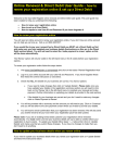
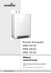
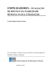
Rapid 25
Rapid 32
Operating Instructions
Installation of the appliance may only be carried out by an installer/competent person.
Please ask your installer to instruct you on how to fill and bleed the appliance and the
installation and on their operation. Strictly abide by all the instructions and warnings.
Always use the appliance in accordance with the Operating Instructions. It is forbidden to
interfere with a sealed component.
CONTENTS
1
Operation of the appliance
2
1.1 Operation of the central heating ................................................................. 2
1.2 Operation of domestic hot water supply ..................................................... 2
2
Operation and display read-out
2
2.1 Operating mode on the service display ...................................................... 3
2.2 Changing the settings of the various functions ........................................... 3
3
Start-up
3
4
Faults
3
5
5.1
5.2
5.3
Filling and bleeding appliance and installation
4
Central heating system ............................................................................... 4
Domestic hot water supply .......................................................................... 4
Frost protection ........................................................................................... 4
6
Maintenance
© 2015 Intergas Heating Ltd
4
Subject to change.
1
Intergas Heating Ltd is a licensed member of the Benchmark Scheme which aims to improve the standards of installation and commissioning of domestic
heating and hot water systems in the UK and to encourage regular servicing to optimise safety, efficiency and performance. Benchmark is managed and
promoted by the Heating and Hotwater Industry Council. For more information visit www.centralheating.co.uk. Please ensure that the installer has fully
completed the Benchmark Checklist on the inside back pages of the installation instructions supplied with the product and that you have signed it to say that
you have received a full and clear explanation of its operation. The installer is legally required to complete a commissioning checklist as a means of
complying with the appropriate Building Regulations (England and Wales). All Installations must be notified to Local Aerea Building Control either directly or
through a Competent Persons Scheme. A Building Regulations Compliance Certificate will then be issued to the customer who should, on receipt, write the
Notification Number on the Benchmark Checklist. This product should be serviced regularly to optimise its safety, efficiency and performance. The service
engineer should complete the relevant Service Record on the Benchmark Checklist after each service. The Benchmark cheklist may be required in the
event of any warrranty work and as supporting documentation relating to home improvements in the optional documents section of the Home Information
Pack.
1
OPERATION OF THE APPLIANCE
The purpose of the Intergas Rapid wall mounted gas fired boiler is to heat water and to supply it to the central heating (CH) system
and the domestic hot water (DHW) taps. The heat exchanger comprises of two separate systems for central heating and DHW. The
appliance is fitted with a modulating control. This means that the power is adjusted in line with the required heat. The boiler controller
responds to each call for heat from the heating or the DHW system by igniting the burner and monitoring the flame.
1.1
Operation of the central heating
The call for heat arises as a result of the room temperature being lower than the temperature set on the room thermostat. If at that time
the appliance does not have a call for DHW, the appliance comes on in central heating mode. The central heating temperature control
modulates on the basis of the set central heating supply temperature. This means that when the desired central heating supply
temperature is approached the appliance adjusts the power. The pump for the central heating has a post purge period of 1 minute. The
post purge period may be changed if desired. The pump runs automatically for 10 seconds once every 24 hours to prevent blocking.
1.2
Operation of domestic hot water supply
The DHW system is started automatically as soon as more than 2 litres of water per minute are drawn. During delivery of hot tap water
no heat is supplied by the appliance to the central heating system.
For purposes of fast delivery of hot tap water a DHW comfort function has been installed in the controller. This function maintains the
temperature of the heat exchanger. The DHW comfort function has the following settings:
On: ( LED on) The appliance’s DHW comfort function is turned on continuously. In this mode the heat exchanger will be kept on
temperature to assure instant delivery of hot water.
Eco: ( LED on) The appliance’s DHW comfort function is an intelligent system. The appliance will adapt to the pattern of use of hot tap
water. As a result, the temperature of the heat exchanger will only be maintained in periods during which domestic hot water was drawn
on previous days.
Off: (Both LEDs off) The temperature of the heat exchanger is not maintained, as a result of which the delivery of hot tap water takes a
little time. If there is no need for rapid delivery of hot tap water, the DHW comfort function can be switched off.
2
OPERATION AND DISPLAY READ-OUT
1
A
1
2
3
4
5
6
7
8
9
10
B
2
C
3
4
D
E
Read-out
On / off
CH operation or setting maximum CH temperature
DHW operation or setting DHW temperature
Desired temperature of CH or DHW in °C / CH water pressure (bar) / Fault code/ Time
Clock “on” CH enabled
Clock “off” CH disabled
DHW comfort function eco
DHW comfort function on (continuous)
Operating code
Flashes to indicate fault
5
F
A
B
C
D
E
F
G
H
6
7
G
8
9
10
11
H
Operation
On / Off button
DHW / CH button, for setting desired temperature
- button
+ button
Clock function setting
DHW comfort function off / eco / on
Service button
Reset button
2
2.1
—
Operating mode on the service
display:
Off (appliance frost protection active)
Wait mode
0
1
2
CH pump post run
Desired temperature reached
Self test
3
4
5
6
7
Ventilate
Ignite
CH mode
DHW mode
Heat up appliance
Note: When the red LED above the reset key flashes a fault has occurred. A fault code will then appear on the temperature/clock display.
2.2
Changing the settings of the various functions
Keeping the key pressed for 2 seconds takes you to the user settings menu (LED at
and the display starts to flash).
Then each time you press the key a different function LED will start to flash. The value of the function can be set using the
and keys. The value set is displayed on the display.
•
The reset
key closes the settings menu and stores the changes.
•
If no key is pressed for 30 seconds, the settings menu is automatically closed and the changes are stored.
•
The on/off
•
The
key closes the settings menu without storing the changes.
button restores the default setting for the switch moments (hold for 5 seconds).
•
By pressing the
•
By pressing the
or
button 2 time blocks can be programmed in which the CH is on (switch moments 1 to 4).
keys the clock can be set and the switch moments can be defined.
•
By pressing the
button the new times will be stored in the boiler controller. In the display appears [P] for a short period.
•
Pressing the button for less than 1 second the following additional functions can be activated:
1. t-on (temporary on), the boiler will respond on every CH demand from the room thermostat until the next switch moment.
2. c-on (continuous on), the boiler will respond on every CH demand from the room thermostat without any time limit.
3. OFF, the boiler will not respond on any CH demand from the room thermostat.
The maximum CH supply temperature. Can be set between 30°C and 90°C (standard setting 80°C).
Low setting for moderately cold weather, high setting for colder weather.
DHW temperature. Can be set between 40°C and 65°C (standard setting 55°C).
All other alterations of settings of the boiler may only be carried out by your installer.
3
START-UP
Once the appliance has been connected to water, gas and electricity supplies and checked by
an authorised installer, the appliance can be started.
Please check the following points:
• The central heating system and domestic hot water system must be well filled and bled.
• The appliance must be switched off (Horizontal dash on service
display, other LEDs off).
• The water pressure in the central heating system must be between 1 and 2 bar (Shown on the temperature display).
Never switch the appliance on if the appliance, the CH system and the DHW system have not been completely filled and bled.
• The room thermostat must be set below the temperature in the room.
• The gas tap must be open.
• Switch the appliance on with the on/off key in the display (The LED lights up, and the service
display goes out). The appliance
may now heat up for purposes of the DHW system until the heat exchanger reaches the set temperature.
• Set the clock and the switch moments. If the boiler is in a time block that CH is not active the boiler must be set in c-on (see §2.2).
• Set the room thermostat higher than the actual room temperature. The appliance will fire for purposes of the CH system.
4
FAULTS
If the following simple appliance faults occur, they can be resolved as follows. In the case of repeated occurrence or other faults
always notify your installer.
1. The CH system does not heat up or does not become sufficiently warm:
• Increase the temperature setting at the room thermostat.
• Open the radiator valves.
• Increase the CH water temperature setting using the and the and key on the operating panel (see §2).
• Bleed the appliance and installation and check the CH water pressure.
2. The domestic hot water supply does not become hot or hot enough:
3.
• Open the domestic hot water tap further.
• Set the domestic hot water temperature higher using the and the and key on the operating panel (see §2).
The fault LED above the reset key is flashing. The following codes are indicated on the display (4):
•
1 The appliance becomes too hot, there is insufficient flow. Open the radiator valves, bleed the appliance and
installation and check the CH water pressure. If necessary top up (see §5 )
• 4 The burner does not light. Consult your installer.
After rectifying the fault press the reset button and the appliance will start up again. For the meaning of the other operating and
fault codes please refer to the installation instructions.
3
5
FILLING AND BLEEDING THE APPLIANCE AND INSTALLATION
NB: Switch the appliance off with the
5.1
key. Do not switch the appliance on again until after filling and bleeding.
Central heating system
In order to guarantee a successful operation of the CH installation the water pressure in the system in case of a cold system should be
between 1 and 2 bar.
If the pressure is too low, the system should be topped up.
Proceed as follows:
• Connect the filling hose to the drinking water tap and fill the hose with water until there is no longer any air in the hose.
Filling is only allowed via an approved filing loop that has check valves fitted.
• Connect the filling hose to the filling / drain tap at the bottom of the appliance.
• Open the drinking water tap and then the filling / drain tap.
• Fill the appliance and the system until a cold water pressure between 1 and 2 bar is reached.
• Close the filling / drain tap and then the drinking water tap.
• Bleed the system and the appliance.
The appliance bleeding point is located at the top left on the appliance.
The system can be bled via the bleed taps on the radiators and/or an air bleed in the piping.
• Check that after bleeding the system the water pressure in the installation is still between 1 and 2 bar; if not, repeat the procedure.
If the system has to be filled more frequently than a few times a year, notify your installer since this means that there is probably a leak.
5.2
Domestic hot water supply
Pressurise the DHW part of the appliance by opening the main tap and/or the inlet assembly.
Remove air from the appliance and the pipe work by opening a hot water tap. Leave the tap open until all the air
has disappeared from the appliance and the pipe work. Close the hot water tap.
Check the connections for leakage.
5.3
Frost protection
To prevent freezing of the condensate drain, the appliance should be installed in a frost-free room.
The appliance is equipped with frost protection which, as long as mains current is present, switches on the CH pump
and if necessary the burner when the heat exchanger temperature falls too far.
NB: If an internal or external frost thermostat has been installed in the system and connected to the appliance, it is not active when the
appliance has been switched off at the operating panel ( - on service
display).
6
MAINTENANCE
The appliance can be cleaned with a damp cloth. Do not use aggressive or abrasive cleaning agents or solvents.
The appliance and the installation should be checked and where necessary cleaned annually by a registered
installer. The same applies to the flue pipe and air supply pipe.
If you smell gas or are worried about gas safety please call the National Gas Emergency Service at 0800 111 999.
For more details visit the website of the National Grid www.nationalgrid.com/uk/Gas/Safety/Emergency.
Always use a Gas Safe registered engineer to fit, fix or service your gas appliance. To find or check an engineer call Gas Safe
Register’s free helpline on 0800 408 5500 or visit www.GasSafeRegister.co.uk.
Intergas boilers are manufactured in a Kiwa ISO 9001 certified production faccility.
Intergas Heating Ltd
Intergas Heating Ltd
Building 94, Bay 1 Vantage Point
The Pensnett Estate
Kingswinford
West Midlands
DY6 7FS
88877700.docx
Tel: 01527 888000
Fax: 01384 279480
[email protected]
www.intergasheating.co.uk
4