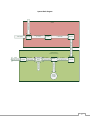
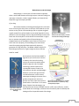
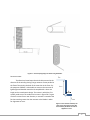
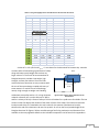
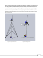
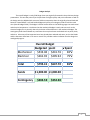
1
B.E.A.S.T. [Backpackable-Easily-Assembled-Sustainable-Turbine] Final Design Report December 7, 2010 Sean Smith - Mechanical Engineer - Project Manager Joshua Gibb - Mechanical Engineer Moses Rotich - Electrical Engineer Yixiao Zhang - Electrical Engineer Table of Contents Requirements Specification ......................................................................................................................... 4 System Design ........................................................................................................................................... 8 System Overview ............................................................................................................................. 9 Block Diagram...................................................................................................................... 10 Functional Description on Blocks ........................................................................................... 11 Subsystem Design............................................................................................................................... 13 Efficiency Discussion .............................................................................................................. 14 Weight Budget ....................................................................................................................... 18 Alternator Selection ............................................................................................................... 19 Mechanical Design ........................................................................................................................ 22 Blade Selection and Hub .................................................................................................. 23 Gearing.............................................................................................................................. 27 Furling and Directional Vane ............................................................................................ 30 Stand ................................................................................................................................ 40 Housings ........................................................................................................................... 42 Electrical Design................................................................................................................... 44 Electrical System Overview ............................................................................................... 45 Battery Selection ............................................................................................................... 47 DC-DC Converter ............................................................................................................... 49 Voltage Monitor Circuits ................................................................................................... 52 State of Charge Indicator .................................................................................................. 57 DC-AC Inverter .................................................................................................................. 58 Project Management.......................................................................................................................... 60 Budget Analysis .............................................................................................................................. 61 Work Breakdown and Schedule Analysis ....................................................................................... 63 References .......................................................................................................................................... 68 Appendix A: Blade and Hub .......................................................................................................................... Appendix B: Furling and Directional Fin ........................................................................................................ Appendix C: Stand .......................................................................................................................................... Appendix D: Housings .................................................................................................................................... 2 Appendix E: DC-DC Inverter ........................................................................................................................... Appendix F: Voltage Monitor 1 ...................................................................................................................... Appendix G: Voltage Monitor 2 ..................................................................................................................... Appendix H: State of Charge Indicator .......................................................................................................... All figures, tables, and equations will be labeled according to section via the below letter code. Section System Overview Efficiency Discussion Alternator Selection Blade Selection and Hub Design Gearing Furling and Directional Vane Housings Battery Selection Electrical System Overview DC-DC Convertor Selection Voltage Monitor State of Charge Indicator Power Inverter Letter Code SO E A BL G F H BA ES DC VM SC I 3 Requirements Specification 4 Backpackable Easily-Assembled, Sustainable Turbine (BEAST) Requirements Specification Sean Smith, Josh Gibb, Moses Rotich, Yixiao Zhang Overview: Many of us are dependent upon our small electronics ranging from cell phones to laptops for functions varying from information gathering to long distance communication. Unfortunately all of these devices are dependent upon electricity in the form of rechargeable batteries which only last for a set period of usage time and then depend on a steady source of electricity for recharging. On extended stays in areas which do not offer an electricity source, an environmentally-friendly, sustainable, and easily implemented power source is needed. The BEAST will be a solution to that problem intended specifically for long-term trips into remote areas and visits to developing nations where a base camp is required. Military applications and disaster relief efforts are also key markets. The device will consist of a wind turbine that can fit within or on a hikers’ backpack at a reasonable weight, be easily assembled in the field with little technical prowess, and supply enough power to efficiently charge cell phone and laptop batteries. The Deliverables 1. Working Wind Turbine 2. System Specifications 1. Code and electric schematics/MULTISIM 2. CAD drawing 3 Testing Report 4. Users’ Manual 5. Final Report Principles of Operation The user will assemble the turbine onto a tripod and securely fasten it to the surroundings. The blades of the windmill will capture energy from available wind and use it to turn an electric generator. An energy storage device will capture the generated electricity, allowing the captured energy to be used at the convenience of the user. A standard United States (NEMA type B) AC outlet (the type typically used in household applications) will be attached to the energy storage device. The charge amount and generation rate will be displayed to the user. The user can then choose to detach the energy storage device from the turbine and use it off-site or charge their device while the storage device is still attached to the turbine. Input: The input will be whatever wind energy is available. The system will start generating given at least a 4 m/s breeze and be able to handle wind gusts up to 20 m/s and then stop generation in order to 5 protect the internals of the device. Output: The turbine will be rated to produce at least 15 W given a 6 m/s wind speed at sea level. The energy storage device will contain at least 200 Wh of energy (enough to charge about 3 typical laptops) and an inverter will be used to supply 125 VAC 60Hz through a NEMA Type B outlet. Technical Requirements 1. Power Generation: The generator should produce at least 15 W given a 6 m/s wind (typical ground level wind speed) and 130 W at 12 m/s (the typical wind speed used to rate wind turbines). 2. Energy Storage: At least 200 Wh will be stored in a durable and safe energy storage device. This will provide enough energy to charge 3 typical 6-cell laptop batteries. The storage device will be detachable and portable for use away from the turbine. 3. Electrical Safety: When the storage device is full, electricity will cease being supplied to the storage device. All wires and circuitry will be able to handle the maximum amount of current produced by the turbine. 4. Mechanical Safety: The mechanical parts will be stable and able to withstand the high shear and bending stresses placed upon them. A housing will cover the gearing and the turbine in order to protect the user. The lowest point at which the blades spin will be at least 2.13 m off of the ground. 5. Portability: The turbine and all of its components should fit within a large backpacking backpack (85 + liter) and weigh less than 23 kg. It should be easily assembled within an hour after one practice trial by two individuals who have read the user manual using only basic tools (screwdriver, wrench, etc.). 6. Durability: The system will be able to withstand frequent assembly and dis-assembly and still be operational. The electrical components will be contained in a water-resistant housing. 7. User Interface: The rate at which the energy is being produced and the amount of charge available (empty to full) in the energy storage device will be indicated. A 125 VAC 60Hz NEMA Type B outlet will connect devices to the storage device. Testing Plan: 1. The wind tunnel in the Ulrey will be used to supply a 6 m/s, 12 m/s, and 20 m/s wind speed to the turbine. The current and voltage going into the battery will be measured at each of those speeds. 2. The battery will be fully charged and then drained with a run-time test. 3. The wind speed will be increased to 20 m/s to check for mechanical stability of the blades and hub. A force that simulates the maximum force applied under peak operating conditions will be manually applied at the hub while the stand is fully assembled and anchored, in order to check for the stability of the stand. 4. The entire device will be weighed, disassembled, and placed in a backpack. Three separate groups of two volunteers will assemble the device with any necessary tools supplied. The average of the completion times of the second attempts must be one hour or less. 5. The device will be assembled and dis-assembled several times to check for durability. The water resistant electronics housing will tested while empty by measuring the relative humidity inside, then spraying it with water, and then measuring the relative humidity again. If the relative humidity increases 6 by less than 20% relative humidity it passes the test. 6. The indicators will be tested before final installation by measuring known values using them. A multimeter will be used to verify the outlet’s output while a laptop and a cell phone are being charged individually. 7 System Design 8 System Overview The finished wind turbine will deliver electricity to a NEMA Type B outlet (standard in U.S. homes) by converting wind energy into mechanical rotational energy and then converting that mechanical energy into electrical energy. The wind energy will be captured by blades that are attached to a hub that is free to rotate. The hub will be elevated on a stand such that the lowest point that the blades spin will be at least 2.13m above the ground. The rotation of the hub will turn the shaft of an electricity generator and thus convert wind energy into electricity. The produced electricity will then be stored in a battery and the battery will supply electricity to an outlet via an inverter. An indicator will tell the user how much power is being produced instantaneously and how much power is available in the battery. The battery pack will also be removable for transportation or use away from the turbine. For the wind turbine to be used the blades must be attached to the hub and the hub must be attached to the top of a collapsible stand. The stand will have sections that are approximately 1m in length and when fastened together achieve a height which causes the blades to be at least 2.13 m (7 ft) off of the ground. Each section will have attachment points for tethers that can be attached to the surroundings for stability. The wind turbine and all of its components will be able to be collapsed into a space no greater than 85 liters (figure SO.1) and weigh no more than 23 kg. During high winds the furling mechanism of the wind turbine will automatically turn it out of the wind so that over-speed of the generator does not occur. Since it may be desirable to disassemble the wind turbine when the wind is blowing, a hole will be placed in the tail fin allowing for a hook on a pole to be used to manually furl the turbine. The turbine will be a complete assembly of the turbine, blades, stand, tethers, battery pack and circuitry. Figure SO.1: An Osprey Argon 85 L hiking backpack will be able to hold BEAST. It is rated to hold up to 30 kg comfortably. 9 System Block Diagram Wind Direction Stand Wind Speed Furling Controller Limited wind speed (0-15 m/s) Blades 0-1000 RPM DC Power (0-74 V, 0-11 A) Water Resistant Electronics Housing Power Inverter DC power 0-12 V, 0-20 A On/Off Button Switch DC power 0-12 V, 0-20 A Battery DC power 13.5-18 V, 0-3.0 A Charge Controller Voltage (0-12 V) User Intervention Outlet 115 V AC, 0-1.74 A Alternator Percent Charged Indicator 10 Functional Description of Blocks Stand: Raises the wind-turbine up to more productive winds and keeps the lowest blades at least 2.13 meters off of the ground. The stand provides support in winds up to 20 m/s. Furling Controller: Limits the effective wind speed acting on the blades by turning the blades out of the wind up to 90 . This mechanical controller acts as protection against large wind force and keeps the turbine operating at a safe speed. Inputs: Wind speed (0-20 m/s) and direction Outputs: Effective wind speed from 0-15 m/s Blades: Mounted on the input shaft, the blades convert the effective wind speed into a usable torque. Inputs: Effective wind speed from 0-15 m/s Outputs: 0-1000 RPM Alternator: A permanent-magnet DC alternator which converts the mechanical energy of the blades into electrical energy. Inputs: 0-1000 RPM Outputs: DC power (0-74V, 0-11 A) Water Resistant Electronics Housing: Provides water resistance to the electronic circuitry. Charge Controller: Converts and regulates the power coming from the generator into a proper power for charging the battery. It also prevents charge backflow and calculates the battery charging rate. Inputs: DC power (0-74 V, 0-11 A) Outputs: DC power (13.5-18 V, 0-3.0 A) Battery: A battery which stores at least 200 Wh of energy. Inputs: DC power (13.5-18 V, 0-3.0 A) Outputs: DC power (12 V, 0-20 A) Percent Charged Indicator: Indicates the percent charge available in the battery. Inputs: Voltage (0-12 V) Outputs: Visualization of the percent charge available in the battery 11 On/Off Switch: Determines if the energy available in the battery is to be converted to AC. Inputs: DC power (0-12 V, 0-20.0 A) and human intervention Outputs: If the switch is on then 12 V DC will be allowed through, otherwise no current will be allowed past this point. Power Inverter: Converts the DC into a usable 115 V AC which is supplied to the user via a standard outlet. Inputs: DC power (12 V, 0-20 A) Outputs: AC power (115 V AC, 0-1.74 A) 12 Subsystem Design 13 Efficiency Discussion The efficiency of a power generation system is a key factor for the overall effectiveness and viability of that system. The BEAST is no exception, which is why this design emphasizes efficiency for key components. The efficiency of the power generating components, namely the blades and the alternator, were assumed to be competitive when specifying the system’s capabilities. The output of the generator stated in the requirements specification, specifically a 15 W output given a 6 m/s wind velocity and 130 W given a 12m/s velocity, were chosen with an assumed 20% efficiency for the output of the generator. This means that the amount of power leaving the generator and entering the charge controller ought to be at least 20% of the overall power available in the wind. In order to understand the design point for BEAST and its relation to other wind turbine designs, it is important to understand the total amount of power available in the wind as well the means in which that energy is captured by the turbine. The overall power available in the wind can be derived from a mass balance over the surface of the blades (figure E.1). The result is shown in eq. E.1 Figure E.1: Mass balance across a wind turbine’s blades. E.1) where is the density of the air, is the swept area of the blades, and is the incoming wind speed velocity. However no turbine can capture all of the energy from the wind, in fact Albert Betz a German physicist in the early 20th century derived the limit for wind turbine energy capture. Betz’s limit describes the maximum coefficient of performance of wind turbines: E.2) E.3) Therefore a corrected form of eq. E.1 would be: E.4) Figure E.2 describes the coefficient of performance for differing tip-to-speed ratios E.5) Tip-to-Speed Ratio: where is the angular velocity of the rotor, is the radius, and is the velocity of the wind. It can be inferred from figure E.2 that the Cp of wind turbines decreases when additional blades are added, and that the most efficient designs tend to use three blades. In fact most well designed, large, commercial turbines have Cp values ranging from 0.3 to 0.451. From this information it may appear that the design point of 0.2 for BEAST was set well below these values for Cp, however it was not Cp that was used as 14 the design point, but rather the efficiency of the entire generator: the blades, any gearing, and the alternator. Figure E.3 shows the systems of BEAST which will contribute to most of the power losses. 1 Figure E.2: The Cp's for various rotors as a function of the tip-to-speed ratio . Power in wind Blades Gears and shaft Alternator Wiring Charge Controller Battery Inverter Losses due to areodynamics Losses due to friction Losses due to back EMF and friction Losses due to wire resistance Losses due to resistance Losses due to resistance Losses due to resistance ηbl ηg ηa ηw ηc ηb ηI Power to outlet ηsystem Figure E.3: All of the subsystems shown contribute to the overall efficiency of the system 15 E.6) E.7) Table E.1: The estimated efficiencies of the subsystems of BEAST. E.8) The values for all of the subsystem efficiencies, with the exception of the blades and the alternator, shown in table E.1 were estimated by internet searches for typical values for those components. The efficiency of the alternator was found at 1160 RPM from the specification of the alternator that was selected (more information on that is available in the alternator selection section of this report), and the efficiency of the blades was back calculated from that value using eq. E.7 with . Thus from table E.1 and figure E.2, the calculated value for Cp is at the lower end of the typical range of 3 bladed wind turbines. Also, the overall estimated efficiency of the system can be found from eq. E.6 to be: E.9) E.10) E.11) Even though may appear to be quite low, the outputs outlined by the requirements specification are still met. First of all, as was already mentioned at the beginning of this section the outputs specified were for the power coming directly out of the generator, not out of the outlet. In order to determine if BEAST meets the specifications, Excel was used to generate a table of outputs at various wind velocities. Table E.2 on the following page was generated using equations E.1, E.4 where , E.10, and E.11; the results were also plotted as shown in figure E.4. When table E.2 is consulted it becomes apparent that the requirements outlined are indeed met both by the generator and by the overall system. 16 Table E.2: The outputs of BEAST are compared to the power in the wind and an "ideal" turbine. The requirements for output should be exceeded. Wind Velocity m/s 1 2 3 4 5 6 7 8 9 10 11 12 13 14 15 Power Available watts 1.2 9.3 31.4 74.3 145.2 250.9 398.4 594.7 846.8 1161.6 1546.0 2007.2 2551.9 3187.3 3920.3 Power Produced by and Ideal (Cp=.593) Turbine watts 0.7 5.5 18.6 44.1 86.1 148.8 236.3 352.7 502.1 688.8 916.8 1190.3 1513.3 1890.1 2324.7 Power Produced by Power Output to BEAST's Generator BEAST's Outlet watts watts 0.2 0.1 1.9 0.9 6.3 3.0 14.9 7.1 29.1 13.8 50.3 23.8 79.9 37.8 119.3 56.5 169.9 80.4 233.1 110.3 310.2 146.9 402.7 190.7 512.0 242.4 639.5 302.8 786.6 372.4 Power Available Power Produced by and Ideal (Cp=.593) Turbine Power Produced by BEAST's Generator Power Output to BEAST's Outlet 4000 3500 Power (watts) 3000 2500 2000 1500 1000 500 0 0 2 4 6 8 10 12 14 Wind Velocity (m/s) Figure E.4: Recall that the power generated is a cubic function of wind velocity. 17 Weight Budget Due to the portable nature of this project, it was deemed important to keep track of the total amount of weight contributed by the various subsystems as shown below. From the weight budget summary, it is evident that the design of BEAST is still well under the design point of 23 Kg of total mass. By far the heaviest items in the list are the alternator, the battery, and the stand as a whole; however increased weight in those areas is justified by the increased efficiencies associated with their quality craftsmanship. Description Alternator Blades, 3 pcs. Housing, Electronics Hub Stand Base Tubing Stand Pins Stand Tethers Stand Tubing Bottom Stand Tubing Middle Stand Tubing Top Tail, Rod, Aluminum Tail, Spade, Plexiglas® Battery Inverter Approximate Total Weight Contingency Weight Budget Quantity Weight per unit (lbs) Total Weight (lbs) Further Details Total Weight (kg) 1 11 11 4.99 1 2 2 0.91 1 1.63 1.63 0.74 1 0.7 0.7 1/4 t, 6" D 0.32 3 1.62 4.86 0.73 6 0.025 0.15 0.01 1 1.5 1.5 0.68 1 2.46 2.46 1.12 1 2.04 2.04 0.93 1 1.62 1.62 0.73 1 1.62 1.62 0.73 1 0.41 0.41 0.19 2 3.35 6.7 1.52 1 0.85 0.85 0.39 37.54 12.46 13.98 9.02 18 Alternator Selection The alternator was the most pivotal of all of the components to select; it forms the link between the electrical and mechanical systems, dictates a large portion of the overall system efficiency, and limits the amount of power that can actually be generated by the system. The ideal alternator meets several criterions: 1) Rated to produce high voltage at low RPM: allows for power generation at lower wind speeds. 2) Brushless: Less friction means less losses 3) Produces direct current (DC): Allows for battery charging without power inversion Figure A.1: The DC-540 Low Wind Permanent Magnet Many different options were considered, including using old Alternator was chosen for its efficiency and quality of build. DC motors and reversing them but eventually the field was narrowed down to four options as shown in the table below. Table A.1: The DC-540 suits BEAST better than any other alternators that were researched. Alternator Attribute Summary Manufacturer Ametec Anaheim Automation Criteria Ametec 30 BLY343S-30 Brushless RPM Voltage Weight (lb) Rated Output (W) Price Torque No 0-1000 30 8 240 $120.00 YES 3000-4200 30 5.7 440 $217.50 1.386 Extras? Must buy used Windblue Power Windstream Power DC-540 Low Wind Permanent 443541 Permanent Magnet Magnet Alternator DC Generator Yes 0-2000 0-200 11 180 $250.00 No 0-5000 9.2 120 $250.00 3 Phase optional; Designed for direct drive wind generation; reaches 12V at 150 RPM The DC-540 low wind permanent magnet alternator (figure A.1) was selected because it had top of the line quality, a built in rectifier, a brushless design, reached charging voltage at a very low RPM, and was designed specifically for low-wind generation. It is the heaviest of the designs, but its increased efficiency and quality offsets this negative attribute. The DC-540 also had more manufacturer specifications available than any of the other options. The efficiency, output, and dimension data as supplied by the manufacturer are shown in the figures A.2 through A.4. 19 Figure A.2: Outputs of the alternator from the manufacturer’s specifications. 0.70 49 rpm 117 rpm 0.60 209 rpm 275 rpm 365 rpm DC-540 Efficiency, h [~] 0.50 490 rpm 650 rpm 0.40 870 rpm 1160 rpm 0.30 0.20 0.10 0.00 0 5 10 15 20 25 30 Electrical Resistance Setting, R [W] 35 40 Figure A.3: Efficiency of the DC-540 for different resistive values and RPMs according to the manufacturer 20 Figure A.4: Dimensions of the DC-540 21 Mechanical Design 22 Blade Selection and Hub Design Blade design is a critical part of the wind turbine especially when a small blade diameter with a high output is desired. Finding the right type, orientation, number, length of blades, and material was important to get the output specified. Lift or Drag Wind turbine blades can be drag based (figure BL.1) and catch the air thus using the direct force on the face of the blade to turn the turbine or they can be a lift based design (like an airplane wing)and actually create lift to pull the blades into the wind (figure BL.2). A key difference in the two designs it that a drag based design cannot travel faster than the wind (which is what allows the anemometer in figure BL.1 to measure wind speed), while a lift based design can indeed allow the tip of the blade to travel faster than the wind itself. Due to this property, lift based designs are much better suited for supplying the high RPMs required for electricity generation at a high efficiency. The blades in BEAST will be a lift based design because of it is lighter weight and more efficient. Figure BL.1: An anemometer measures the wind velocity; it is both a vertical axis and drag based design. HAWT or VAWT B A Figure BLI.3: HAWT (A) are more efficient than VAWT (B). Horizontal axis wind turbines (HAWT in figure BL.3.A) are much more common in industry than their alien looking cousins the vertical axis wind turbines (VAWT in figure BL.3.B). The HAWT technology is better explored and represented because it tends to be more efficient, durable, and lightweight. However a vertical axis approach was considered because it offers several advantages including the location of the gearbox and generator nearer the Figure BL.2: The lift force causes a resultant ground, less noise, lower start up wind force in the direction of rotation by using speed and the “wow factor” of an exotic aerodynamic principles. design. Despite those advantages, the horizontal axis was chosen for BEAST because it offers more efficiency, smaller overall blade size and weight, and better ease of assembly and dis-assembly thus lending itself to the portable needs of the design. 23 Number of Blades An important check for the quality and efficiency of blades are their tip-to-speed ratio (ratio of the velocity tip of the blade to that of the incoming wind). This concept is further discussed in the efficiency portion of this report. In figure E.2 in the efficiency discussion the efficiency of various blade configurations was compared for varied tip-to-speed ratios. According to that figure three bladed designs have the greatest potential for high efficiencies. Two bladed designs are also rather efficient and offer the advantage of less weight and higher RPMs, however they do not provide as much torque as a three blades. Because of its potential for higher efficiencies and the balance it provides between torque and RPMs a three bladed design will be used for BEAST. Length of the Blades The length of blades determines the total diameter of the turbine and thus the swept ares which in turn determines the total amount of power that can be extracted from the wind (equation BL.1). More information on the development of eq. BL.1 is available in the efficiency section of this document. BL.1) BL.2) where is the efficiency of the blades, is the density of air in kg/m3, is the area swept by the turbine blades in m2, is the velocity of the wind in m/s, and is the efficiency of the generator as outlined in the efficiency discussion. The requirement specifications were estimated by using a total blade diameter of 1 m (which seemed to be reasonable for a portable design) and the efficiency of the generator to a conservative 20% and to (the density of air at sea level). It can therefore be reasoned that if the blades are 1 m or slightly greater in diameter, than the power output ought to meet the requirements without being too heavy. Material Ideal materials for turbine blades are lightweight, strong, durable, and easily shaped to specific profiles. Historically blades have been made out of wood, thin strips of aluminum, fiberglass, and plastic composites. It was determined that the best material for BEAST would either be fiberglass or a plastic composite due to their especially lightweight designs that typically involve efficient profiles due to their mold-ability. Blades Selected Designing a complex lightweight blade profile in house would involve computation fluid dynamics beyond the scope of this design and constructing one would be difficult at best. Therefore it was decided to purchase the blades. A search for turbine blades that met the one meter diameter specification was conducted. Only two blades that had a diameter near to 1 m could be found. The blades that were eventually selected shown in figure BL.4 were less expensive and also slightly larger; 24 than the others a comparison of the two blades was actually found on the site where the blades were purchased (greenergystar.com) and is available in the appendices. Figure BL.4: The blades selected are molded out of a strong and lightweight nylon/carbon-fiber composite to exacting specifications. The selected blades have a 1.57m diameter when mounted on a 0.101m diameter hub and the total weight of the three blades is 0.9 kg due to the nylon/carbon fiber construction. The material does bend easily and therefore is designed such that the mounting surface causes the blade to be angled towards the direction of the wind when mounted (Fig. BL.1). When in operation, the force of the wind on the blades causes them to bend back away from the wind and become parallel to the mounting hub. Figure BL.5: Forward-angled mounting of airfoil blades The hub that holds the blades is designed based on the number of blades and the diameter of the threaded shaft of the alternator. The hub is circular because it is a rotational hub and the blades are evenly spaced around the circle of the hub to balance the fan (Fig. BL.6). 25 Alternator Shaft Hole Blade Mounting Holes Figure BL.6: Hub for Mounting Blades to Alternator The threaded shaft of the alternator is 0.875in standard thread and the hub is drilled in the center so that it fits over the shaft and is secured by a nut and lock-washer. To disassemble the fan the bolts that hold the blades on the hub must be removed. The hub may remain attached to the alternator. The hub design considers not only blade spacing but also the stress applied to the hub material as the blades spin and their inertia attempts to pull them away from the center of the hub. The stress is applied to two 6mm bolts. The stress applied to the material is found from BL.3) where the area is the diameter of the hole multiplied by the thickness of the material. The force from each blade is found from BL.4) where is the angular speed in rad/s. To find the maximum force that can be achieved the maximum rotational speed of 157 rad/s (1500 rpm) that the blades can withstand according to the manufacturer is used. The radius of the center of mass was found from a balancing test to be 0.248m and the mass is 0.3 kg from the manufacturer. This yields a force of 1834N. The force on each hole is half of the total force from the motion of the blades. To find the max stress on a single bolt hole use Eq. BL.3 where the area is the diameter of the hole (6mm) times the thickness of the plate (4.76 mm). The max stress turns out to be 64.2 MPa and the yield stress of Aluminum 3003-H14 is 145 Mpa which yields a factor of safety of 2.26. Having a factor of safety this high is not needed but the cost of material is such that purchasing a thinner sheet of aluminum would actually be more expensive. The aluminum tubing is being purchased in a single order and the plate for the hub is being purchased from the same supplier to save on shipping. Technical drawings of the hub can be found in the appendices. 26 Gearing Gearing was originally thought to be a part of the system design acting as a means of increasing the RPM of the input shaft attached to the blades to an RPM suitable for the alternator. However, gearing produces losses, adds weight, and reduces the torque applied to the alternator. This section is not about gearing selection, but rather it is here to provide the justification for a direct-drive gearless design. This justification involves a balance between 1) the specified outputs of the generator, 2) the capabilities and angular velocities of the blades, and 3) the output capability of the generator. First of all, the requirement specification states three distinct design point for output: output must begin given a 4 m/s wind speed, produce at least 15 watts given a 6 m/s breeze, and at least 130 watts given a 12 m/s wind speed. Given that 12 m/s is a very fast wind velocity that rarely occurs, one might ask why it is included at all as a design point. The reasoning involves industry standards which are based on the total power availability for given wind speeds. From Eq. E.1 it is apparent that the power available has a cubic relationship with the wind velocity (figure G.1). However, the average wind speed tends to be relatively low and have a low power density (figure G.2). It is useful then to design a wind turbine to be most efficient at the speed at which the most power is available which can be found by combing the wind power density and wind resource plots into a total power availability curve (figure G.3). From this curve it is apparent that rating a wind turbine for 12 m/s is appropriate. Rating a turbine at higher speeds also has marketing benefits; it sounds much better to a customer to promote a 130 W Figure G.1: The power available in wind increases at 2 a cubic rate with respect to the velocity. turbine than a 15 W turbine. Figure G.2: An example distribution of wind velocities shows a 2 low average wind velocity. Figure G.3: When the power density and wind resource curves are combined, the power available at a given wind speed over long periods of time becomes apparent. 27 Now that the reasoning behind the specified outputs is understood, it is important to investigate the capabilities of the blades selected. In order to accurately calculate the torque output, radial forces, and angular velocities of the blades without testing it would be necessary to perform some sort of computational fluid dynamics for the distinct blade profile. However, performing such an analysis is beyond the scope of this design and would require access to the original design of the blades. Therefore a back door approach was taken to calculating those attributes. The angular velocity of the blades is the most important attribute of the blades relative to the generator and Table G.1: The RPM of the blades for various wind speeds calculated using an the requirement specification. The tip-to-speed ratio mentioned in assumed tip-to-speed ratio of 5.5. the efficiency discussion earlier in this report was used to estimate the angular velocity of the blades in Excel (table G.1). Typical tip-tospeed ratios for three bladed turbines are said to range from 5 to 6 for good designs3; this is consistent with figure E.2 in the efficiency discussion. If a value of 5.5 is chosen for and the diameter of 1.57 m for the blades selected is used, then Eq. E.5 can be rearranged to solve for the angular velocity of the blades at different wind speeds: G.1) G.2) The blade manufacturer states that the blades can spin up to 1500 RPM without harm. From table G.1 this falls outside of the range of reasonable wind speeds. Wind Speed Tip Speed m/s m/s 4.00 22.00 5.00 27.50 6.00 33.00 7.00 38.50 8.00 44.00 9.00 49.50 10.00 55.00 11.00 60.50 12.00 66.00 13.00 71.50 14.00 77.00 15.00 82.50 16.00 88.00 17.00 93.50 18.00 99.00 19.00 104.50 20.00 110.00 RPM 268 335 401 468 535 602 669 736 803 870 937 1004 1070 1137 1204 1271 1338 Finally, relating the capabilities of the alternator to those of the blades shows that BEAST can produce the specified power at all three design points without gearing. All of this justification is taken from the specification sheets supplied by the manufacturer which are available in the appendices. The alternator produces 12 V (enough to start battery charging) with an input RPM of less than 209 which is less than the 268 RPM supplied at 4 m/s thus meeting the first point. At the second design point of 6 m/s the RPM is calculated to be 401 at which point 15 W ought to be produced; from the alternator specification sheet up to 46 W are produced at a lesser RPM of 365 thus meeting this requirement. The third design point of 130 W at 12 m/s has a calculated RPM of 803 while the alternator is rated to produce up to 129 W at 650 RPM and up to 206 W at 870 RPM; thus the third criteria is also most likely met. A summary of these results is shown in table G.2. 28 Table G.2: Summary of results of design points and alternator outputs. Design Point Velocity (m/s) Design Point Design point Alternator Rated Requirement RPM output RPM Output Met? 4 268 12 V 209 15 V Yes 6 401 15 W 365 46 W Yes 12 803 130 W 870 206 W Yes From the previous discussion, it is apparent that all of the design requirements are met with only the direct RPM of the generator being supplied to the alternator. Gearing could still be added in order to increase the input RPM at lower velocities, but due to the portable nature of this design as well as the loss in efficiency, added monetary cost, and time resource cost associated with adding gearing, the BEAST will be a direct drive design. 29 Furling and Directional Vane Furling Mechanism This section explores the design of the furling mechanism as well as the directional vane which keeps the wind turbine facing into the wind. A furling mechanism is any device which protects the turbine from exceptionally high wind speed. Such a device is necessary to prevent the wind turbine from damage due to the reaction forces at the hub caused by the rotation of the blades, overheating and demagnetizing the alternator, and to prevent excess forces on the stand. There are many different means to accomplish this, with some of the most common for small wind turbines considered in table F.1. The different means include a counterweight mechanical controller, a spring mechanism, and computer controller braking. Table F.1: Decision matrix for the means of furling. The counterweight makes use of an angled hinge and the same principle that causes a refrigerator door (or any door for that matter) to move when hung off center. This mechanism is relatively inexpensive, fairly precise, and reliable. However it is by far the heaviest of the three options which is a high weighted criterion due to the portable nature of BEAST. Criteria Weight Counterweight Spring Computer Weight 0.3 1 3 3 Price 0.3 2 3 0 Reliability 0.15 2 0 3 Simplicity 0.15 1 3 0 Precision 0.1 1 0 3 Total Weighted Total 1 7 9 9 1.45 2.25 1.65 The spring controlled mechanism uses preloading of a linear torsion spring to resist the wind force until the furl velocity is reached, then begins furling. It is lightweight, inexpensive, and simple, yet is deficient in precision and reliability. The lack of precision and reliability is the reason this is the least common method used for small wind turbines. However, furling is a last resort that should have a factor of safety for the velocity of furling anyway thus leaving room for lack of precision and exacting performance. A computer controlled mechanism makes use of an anemometer and a microprocessor to track the wind speed and apply a mechanical brake once that velocity is reached. The computer controlled mechanism is lightweight, accurate, and precise and would be ideal for a larger budget on a final commercial unit. Figure F.1: Unfurled wind turbine viewed along the axis of the stand from the top. 30 Due to its relatively simple, lightweight, and inexpensive design, spring furling was chosen as the method of furling. This method of furling involves offsetting the alternator and blades a small amount from the tail vane and the central axis of the stand thus creating a moment caused by the axial force on the blades A torsion spring is then set to resist this moment by preloading the spring to a calculated force given a specified wind velocity. When that velocity is reached, the wind force will overcome that preload and start to turn the blades out of the wind, thus reducing their swept area relative to the wind and therefore the available power (figures F.1 and F.2). From eq. E.1: F.1) F.2) From eq. F.2 it appears that the power available would Figure F.2: The turbine as furled an angle of due to high wind force, thus reducing the effective area. even become 0 when the system is fully furled ( ). This is not entirely accurate because the blades do continue to spin even when they are completely parallel to the direction of wind flow (although at a slower rate than if they were perpendicular to the flow). However, it does convey the theory behind this mode of protection. The calculations involved for furling require an even further understanding of the mass balance across the blades than previously discussed. The first element that must be discussed is the value of the axial force acting on the blades as the wind passes through them. F.3) , where is the axial force, is the mass of the air, is the acceleration of the air, is the time rate of change of the mass of air, is the velocity of the air, is the air density, is the swept area of the blades, is the velocity of the air entering the blades, and is the velocity of the air leaving the blades. If the average is velocity of the air is assumed to be F.4) , Then substituting eq. F.4 into eq. F.3 produces: F.5) If is the efficiency of the blades as described in the efficiency discussion, it can be shown4 that 31 F.6) . Then finally from eq. F. 5 and eq. F.6 the axial force is F.7) . However, it ought to be noted that eq. F. 7 is not entirely accurate for a furled state due to the decreased area. From figure F.2 and eq. F.7 it is apparent that a more accurate equation is given by: F.8) F.9) 100 90 80 % of Original Area 70 60 50 40 30 20 10 0 0 10 20 30 40 50 60 70 80 90 Theta Figure F.3: The effective area becomes an ellipse and follows the curve of Figure F.3 describes the effective area with respect to furling angle. However, ! For a torsion of spring of constant . itself is a function of and an offset of O: F.10) Thus producing as a function of ! F.11) However, for the sake of this design the area will be approximated as constant for force calculations. This means that the final velocity of furl will be higher than that specified for a constant area. 32 Let us explore the ideal furling conditions if a good design is implemented to give a target for BEAST’s design. If the velocity of furling is chosen to be 15 m/s as suggested by the requirements specification and a target for a completely furled state is chosen to be 18 m/s then a spring can be designed and selected with a spring rate suitable for furling between those two states and for resisting furl before 15 m/s is reached. Figure F.3 demonstrates ideal furling for such a case. Figure F.4: The value of “k” was chosen iteratively by varying it in an Excel spreadsheet until the desired conditions were met. The slope of the line between 0 and 90 degrees is “k”. Now that the ideal conditions and goals are understood, the primary design considerations are the offset chosen and the spring constant. The major limiting factor is the availability of springs with low enough spring constants to furl quickly along with high enough tensile strength the withstand the high moment to which they subjected. The spring constant k’ of a torsion spring from Shigley’s Mechanical Engineering Design is given to be are F. 11) F.12) Figure F.5: A torsion spring's linear constant value is determined by many of the properties shown above. F.13) where is the diameter of spring wire, is the modulus of 33 elasticity of the spring material, 10.2 is an empirical value, is the average diameter of the spring, and is the effective number of spring coils, is the number of turns in the spring body, M is the applied moment, and is the angle of rotation from the free position (figure F.5). An Excel spreadsheet was developed that calculates the value for a spring given a varied value of . The values of were then used in another spreadsheet which calculated the values at which furling would begin and end given a specified and preload angle. A value of that meets the criterion for furling between two specified values was not difficult to find, however the spring material itself can only withstand a certain range of moments (table F.2). Unfortunately the actual moments acting on the spring are quite large even for a small offset (table F.3). Table F.2: The diameter of the spring material determines the maximum moment that the spring can withstand. Values for maximum moment were obtained from McMaster's website. d in 0.135 0.125 0.106 0.095 mm 3.429 3.175 2.6924 2.413 Table F.3: The moment acting on the spring varies with the square of the wind velocity. V m/s 10 11 12 13 14 15 16 17 18 19 20 Max Moment lbf-in N-m 42.86 4.842537 34.29 3.874256 22.5 2.542163 17.14 1.936563 M lbf-in 16.96306 20.5253 24.42681 28.66757 33.2476 38.16689 43.42544 49.02325 54.96032 61.23665 67.85225 N-m 1.916569 2.319048 2.759859 3.239001 3.756475 4.312279 4.906416 5.538883 6.209682 6.918813 7.666275 The balance between a quick furl and the actually being able to withstand the moments applied calls for a low value of coupled with a large wire diameter ( and . Given a large wire diameter, the only way to vary the value of is to vary the values of D and . Using the Excel spreadsheets mentioned above, it was determined that for Table F.4: Summary of the designed spring characteristics. d=3.175, D= 44.45 mm, and Na=48 an acceptable value of is found to furl up to between 12.5 and 14.2 m/s given a preload angle (figure F.6 and table F.4). Spring Characteristics Material d D Nb l Free Body Length length of wire K' Music Wire 3.175 44.45 48 101.6 152.4 558.8 14.93 mm mm mm mm mm N-mm/degree 34 Figure F.6: The furling response for the designed k'. Unfortunately spring manufacturers do not commonly sell springs with that many coils. It is possible to have one custom manufactured, but that is falls outside of our budget; a manufacturer of springs was contacted for a quote on custom springs and the price of $160 was given. Given that a spring which meets the requirements cannot be readily purchased, at this point there are two options: either change designs or find a way to manufacture the spring in house. After a quick internet search, the actual manufacture of the spring would not be too difficult, so that is the route chosen. Music wire with a diameter of .125 in can be purchased in a 24 ft roll for a reasonable price. This wire will then be rolled around a rod of appropriate diameter while being heated by a torch. The final spring will be quenched in vegetable oil and then subjected to 3 rounds of heat treatment in an oven. The final spring design is shown in figure F.7. 35 Figure F.7: The final spring design was drawn using Solidworks. Directional Vane The directional vane keeps the wind turbine turned in the direction of the wind by placing a larger amount of area parallel to the flow of the wind in the back of the vane than in the front. For the purposes of BEAST it is desirable to construct the vane out of lightweight and durable material with coupled with a short arm length and an aerodynamic design. The means in which the fin is actually used to turn the turbine can be seen in figure F.8: if a gust of wind is comes from a new direction, a moment is created at the fin that must be greater than the moment at the blades in order for alignment to occur. Ffin Larm O Fblades Figure F.8: The moment created by the force on the wind must be more than that created by the blades in order for alignment to occur. 36 Recall: F.14) , also the force of the wind acting on the fin is given by F.15) where is the drag coefficient for that specific geometry. Now, the moments around the stand by the blades and the fin are given to be F.16) and Table F.5: The drag coefficient of the shape in figure F.9 becomes quite low when L/D =2. F.17) If F.16 and F.17 are compared to each other and solved for the area of the fin, then eq. F.18 results. F.18) L/D 0.5 1 2 4 CD 1.2 0.9 0.7 0.7 Before the area is calculated it is wise to determine the shape of the tail fin. The shape shown in figure F.9 was chosen due L to its ability to be streamlined when aligned with the wind yet still maintain a large surface area for direction change V when necessary. The drag coefficient for wind hitting the D broad side of such a shape can be estimated from similar shapes to be slightly above 1. For the sake of any further l calculations, =1 for the broad side, thus introducing a small factor of safety when F.18) is used to determine a Figure F.9: The semicircle in front causes this shape to be more streamlined while still maintaining a desirable area. The area of the chosen geometry is given in large surface area. eq. F.19 to be F.19) A spreadsheet was generated in Excel to calculate the values of L, specified criteria (table F.6). , and D necessary to meet the 37 Table F.6: The green highlight in the cells indicates that the cell meets the criteria. Vane Area Calculation L/d 2 Larm m 0.5 Cd Ablades 2 1 m 1.935928 Offset Nth m 0.04 0.33 Minimum Vane Area 0.051108497 L m 0.3 0.31 0.32 0.33 0.34 0.35 0.36 0.37 0.38 0.39 0.4 d m 0.15 0.155 0.16 0.165 0.17 0.175 0.18 0.185 0.19 0.195 0.2 l m 0.225 0.2325 0.24 0.2475 0.255 0.2625 0.27 0.2775 0.285 0.2925 0.3 A Factor of Safety Xlocation COM 2 m 0.043 0.045 0.048 0.052 0.055 0.058 0.061 0.065 0.068 0.072 0.076 m 0.158 0.163 0.168 0.173 0.179 0.184 0.189 0.194 0.200 0.205 0.210 0.833 0.890 0.948 1.008 1.070 1.134 1.200 1.267 1.337 1.408 1.481 A value of L=.4 for L/D=2 and = .5 are chosen for the directional fin because they meet the criterion while still maintaining a good factor of safety .40 m along with lower overall weight and size than any larger values of L. The fin will be constructed out of .2 m Plexiglas because it provides a low weight, high strength, and low cost solution. The arm will be .3 m constructed out of aluminum to stay consistent with .21 m the rest of the system design coupled with many of same reasons it is used in the rest of the design, namely a high strength to weight ratio. Bending .50 m calculations were performed on a .5 m long aluminum Figure F.10: A summary of the dimensions of the directional fin. rod with a diameter of 1 in and a thickness of .065 in and for a velocity of 20 m/s a factor of safety of 2.22 is still evident for a yield stress of 110 MPa. The last column in table F.6 displays the location of the center of mass of the shape. This location must be the location at which the fin is attached to the rod in order for the moment calculations to be valid, therefore the end of the aluminum rod must line up with .21 m from the front (rounded edge) of the Plexiglas directional fin (figure F.10).An overall drawing of the furling mechanism and directional fin is available on the next page while details on the individual components can be found in the appendices. 38 Figure F.11: The complete furling and directional fin subsystem. 39 Stand Design The stand for BEAST (Fig. SD.1 & SD.2) is designed to elevate and support the turbine, be a steady platform for its operation, be lightweight, and be easily assembled and disassembled. To meet all of these criteria two designs were considered. A set of three tubes of the same diameter with flared ends that stack was considered but not selected because when the tubes are stored they take up too much volume. A tubular telescoping design with the largest tube at the bottom and two upper sections consecutively smaller supported by anchored tethers was considered and chosen for the upright sections. Three sections of approximately one meter each are used to achieve the required height of the fan. The lowest point that the fan blades my turn is 2.13m as a safety precaution to keep them above average American head height of 1.76 m (www.cdc.gov). Since the uppermost section is the smallest it was analyzed in a buckling load analysis and the results are shown in Table SD.1. The critical buckling load was calculated using Eq. SD.1 where C is an end condition factor, E is the elastic modulus of the material, I is the area moment of inertia, and L is the length of the section being analyzed in meters. It was found that a 0.0127M outer diameter, 0.011m inner diameter aluminum 6061-T6 tube would sufficiently support the estimated load of 67N with a factor of safety of 27 for a single section. A tube of full length of the stand and the same diameters as the uppermost section was analyzed for critical buckling load and a factor of safety of 11 was found. Although the factors of safety are large, a smaller diameter will not be analyzed because the wires from the alternator to the rest of the system will be run through the tubing. Table SD.1: Buckling Load Calculations Buckling Load Calculations Pcr (N) 1.048E+04 2.619E+03 7.282E+03 1.820E+03 7.253E+02 C 1 1/4 1 1/4 1 E (N/m^2) 6.90E+10 6.90E+10 6.90E+10 6.90E+10 6.90E+10 I (m^4) 8.933E-09 8.933E-09 8.933E-09 8.933E-09 8.933E-09 L (m) 0.762 0.762 0.914 0.914 2.896 Ro (m) 0.0127 0.0127 0.0127 0.0127 0.0127 Ri (m) 0.011 0.011 0.011 0.011 0.011 FOS 156 39 109 27 11 The upper section has a 0.0254 OD (outer diameter), the middle section has a 0.03175m OD, and the bottom section has a 0.038m OD and all three sections have a 1.65mm wall thickness. The fan, alternator, and furling device will be pinned to the top of the stand but will be free to rotate so that the fan can turn into the wind. To steady the stand during assembly/disassembly a tripod base was chosen. Three legs are pinned to the lowest vertical section to help steady the device until the 40 tethers are secured. Para-cord 550 is being used for the tethers. It is lightweight, strong (able to hold up to 2.45KN), durable, and inexpensive per unit length and is therefore a good selection for the tethering material. The Para-cord does have a drawback though; because it is thin it elongates up to thirty percent at maximum load. This is potentially a problem because the stand needs to be as rigid as possible but the maximum forces expected should not cause enough elongation of the Para-cord to be a problem. Other tether materials were considered but no other materials provided the same strength to weight ratio as the Para-cord. Figure SD.1: Fully Extended Stand Figure SD.2: Collapsed Stand 41 Housings Upper Housing The requirements specification dictates that a protective housing will enclose the gears and alternator that are mounted on the top of the vertical stand. The housing was intended to protect the user from the gears and vice versa. The selected alternator however, does not require the use of gearing and therefore no gears are being implemented which removes the safety issue of exposed gears. The selected alternator is also an all-weather design and therefore the upper housing is no longer part of the design. Electronics Housing The charging circuit and battery pack need to be kept in a water-resistant enclosure to protect the components of the system. It is also desirable to be able to remove the battery pack from the turbine to use off-site. Having all of the electronics contained will allow for this to be easy and efficient. The housing is water-resistant, and durable enough to handle the weight of all the components as well as the movement from location to location. It is 15.24cm x 19.05cm x 34.29cm to accommodate the inverter, circuit boards, and battery packs (Fig.H.1). The housing will have a water-resistant AC outlet in one end for the user to connect to and a hookup in the other end to attach to the output from the alternator. The outlet will be connected to the inverter by a short electrical cord. The top of the housing will be removable for access to the components. The charge rate and availability indicators will be mounted into the top of the housing for ease of viewing. The size of the housing is determined by the size of the individual components. They are arranged to achieve the smallest housing size possible. 42 INDICATOR AC OUTLET CIRCUIT INVERTER BOARDS BATTERY PACK Figure H.1: Water-Resistant Housing Layout The housing will be made of acrylic sheet because it is strong per unit volume, easily cut and drilled, inexpensive, and impervious to water. The decision matrix for material selection is shown in Table H.1. Table H.1: Decision Matrix for Material Selection Housing Material Selection Criteria Weight of Material Weight Acrylic Sheet Aluminum Wood 0.2 3 2 2 Price 0.25 3 1 3 Easily Assembled? 0.05 1 2 3 Sealability 0.25 2 2 1 Water Resistance 0.25 3 3 0 Total: 1 12 10 9 2.65 2 1.55 Weighted Total 43 Electrical Design 44 Electrical System Overview The purpose of this section is to outline the overall workings of the electrical system. The electrical system is essentially a charge controller. A proper charge controller design needs to take many different factors into consideration. In this particular project, the amount of power generated by the alternator was considered along with how this power could be manipulated to output a desirable voltage in order to charge the battery bank. The charge controller utilizes several electronic components to protect the battery from overcharge and undercharge. Figure ES.1. is a representation of the entire electrical system; all of the subsystems will be expounded upon later in the document. Figure ES.1: Presentation of the entire electrical system The charge controller is composed of four primary parts: a DC-DC converter, two voltage monitors, a battery bank and the user indicators. The block diagram for the whole electrical system is shown in the next page (figure ES.2). Some values of the inputs and outputs in figure ES.2 are different from the overall system block diagram shown in the system design portion of this report. This is due to a more refined electrical design that has been limited and driven by component availability and specifications of those specific parts. First, the DC-DC converter handles a voltage range of 8V to 74V produced by the alternator and provides a 14V, 3A output. The power output from the converter then charges the battery and supplies the DC-AC inverter simultaneously. When the battery is fully charged, the voltage monitor for the battery (voltagemonitor2) outputs a low signal (less than 0.5 V) to the enable pin of the DC-DC converter to open the circuit. The enable pin must be raised above 3V for normal operation. If the enable pin is pulled below 0.5V, the DC-DC converter enters shutdown mode, drawing less than 10 μA from the Vin pin. Then the battery bank continues to supply the DC-AC inverter. When the battery bank’s voltage falls below the appropriate range, the voltage monitor (voltagemonitor2) will send a 45 high signal to the enable pin of the DC-DC converter to close the circuit again and resume charging the battery bank. The state of charge indicator displays the amount of charge in the battery. Voltage monitor1 detects the voltage input for the DC-AC inverter. If the input is in the appropriate range, the green LED will turn ON otherwise, the red LED will turn ON. LED indicator 0 or 11-14.5 V 0-500 mA Alternator 0.5A-4A Voltage monitor1 8V-74V DC-DC converter 11-14.5 V 0-1 A 14V 3A 11V-14.5V <3V when battery is fully charged Voltage monitor2 1A-20A 0-12 V 0-1 A 14 V 0-3 A DC-AC inverter 12V 0-20 A Battery bank 0-12 V 0-1 A State of charge indicator Figure ES.2: Block diagram of electrical system 46 Battery Selection The requirements specified at least 200 Wh of energy storage to be available in the battery. There are several different types of batteries available on the market that could meet those requirements. The properties of the battery types are summarized in table BA.1. Table BA. 1: Properties of various battery types. A decision on battery type was made by Table BA. 2: Decision matrix for battery type. generating a decision matrix (table BA.2) with values ranging from 1 (worst) to 5 (best). Because of their high energy density and relatively low price, NiMH batteries seem to fit BEAST the best. Two 12 V 10Ah NIMH battery packs (figure BA.1) were selected at a reasonable price. They are to be connected in parallel to produce a 12 V battery pack with a total capacity of 240 Wh thus exceeding the requirements. Other higher voltage battery packs were considered because of lower price for the same amount of storage capability. However, 12 V was selected because the alternator produces a 12 V output at much lower wind speeds, thus allowing for a wider range of generation wind velocities. 47 Figure BA.1: Two of the 12 V 120 Wh battery packs shown above will be connected in parallel to meet the requirement of at least 200 Wh of storage. Each pack weighs 3.35 lb (1.52 kg) 48 DC-DC Converter The DC-DC converter is essential for the overall electrical design because it protects the rest of the circuitry from the unstable power fluctuations of the alternator’s output. DC-DC converters essentially “smooth out” their inputs and then output a desired range of voltage and current. It is especially desirable for the purposes of BEAST’s design for the DC-DC converter to accept a very wide range of voltages as its input. This design requirement is driven by the large range of voltages produced by the alternator for the designed generation RPMs (figure A.2 in the alternator selection section). A decision on the DC-DC converter was made by generating a decision matrix (table DC.1) with values ranging from 1 (worst) to 5 (best). The LM 5118, a wide voltage range buck-boost controller, was chosen because it possessed the largest voltage input range available which is the most important design criterion as evidenced by the decision matrix. Table DC. 1: Decision matrix for DC-DC converter. Criteria High range of voltage input Cost Appropraite current output Size Weight Total Weight 0.4 0.2 0.3 0.05 0.05 1 MAX5093 MAX 1703 Ion 5 5 1 5 5 3.8 LM5118 1 5 3 5 5 2.8 5 2 5 5 5 4.4 Because of the high cost for an LM 5118 evaluation board, it was decided to purchase all the individual components and build the circuit in house. Figure DC. 1 shows the application circuit of the DC-DC converter for BEAST. All the components in the circuit that are going to be purchased are displayed in table DC. 2. 49 Figure DC. 1: DC-DC converter 50 Table DC. 2: Electrical BOM list. Part Cboot Ccomp Ccomp2 Cin Cinx Cout Cramp Css Cvcc Cvccx D1 D2 D3 D4 L1 M1 M2 Rcomp Renable Rfb1 Rfb2 Rsense Rt Ruv1 Ruv2 U1 Manufacturer MuRata Yageo America MuRata MuRata Taiyo Yuden Sanyo Yageo America Yageo America Taiyo Yuden Kemet Vishay-Semiconductor Vishay-Semiconductor Vishay-Semiconductor Vishay-Semiconductor Bourns Infineon Technologies Renesas Panasonic Panasonic Panasonic Panasonic Susumu Co Ltd Panasonic Panasonic Panasonic National Semiconductor Part Number Quantity Price Attribute 1 Name GRM219R71C104KA01D 1 0.01 Cap CC0805KRX7R9BB152 1 0.01 Cap GRM219R71H333KA01D 1 0.01 Cap GRM32ER72A225KA35L 5 0.49 Cap HMK212B7104KG-T 1 0.0271 Cap 20SVP100M 5 0 Cap CC0805KRX7R9BB152 1 0.01 Cap CC0805KRX7R9BB183 1 0.01 Cap LMK212B7105KD-T 1 0.017 Cap C0805C105K4RACTU 1 0.02 Cap 30CTH02SPbF 1 0 VFatIo 12CWQ03FNPBF 1 0.74 VFatIo 30CTH02SPbF 1 0 VFatIo 12CWQ03FNPBF 1 0.74 VFatIo PM2120-270K-RC 1 1.2 L BSC100N10NSF G 1 1.48 VdsMax RJK0330DPB 1 0.69 VdsMax ERJ-6ENF1782V 1 0.01 Resistance ERJ-6ENF1004V 1 0.01 Resistance ERJ-6ENF1001V 1 0.01 Resistance ERJ-6ENF1052V 1 0.01 Resistance PRL1632-R013-F-T1 1 0.21 Resistance ERJ-6ENF6192V 1 0.01 Resistance ERJ-6ENF8062V 1 0.01 Resistance ERJ-6ENF1782V 1 0.01 Resistance LM5118MH 1 2.8 Footprint 805 805 805 1210 805 SM_RADIAL_8MM 805 805 805 805 DDPAK DPAK DDPAK DPAK PM2120 PG-TDSON-8 LFPAK 805 805 805 805 1206 805 805 805 MXA20A 51 Voltage Monitor Circuits Voltagemonitor1 Voltagemonitor1 (figure ES.2 in the charge controller section of this report) is responsible for detecting the voltage input of the DC-AC inverter and then indicating via an LED whether or not it is safe to use the outlet. The MAX 6458 was chosen as a voltagemonitor1 because of its high supply voltage; it can operate over a 4V to 28V supply voltage range. The MAX6458 includes two comparators (one overvoltage and one under voltage) for window detection and a single output to indicate if the monitored input is within an adjustable voltage window. A presentation of the application circuit of MAX 6458 is shown in figure VM.1. Vcc is the input voltage. Figure VM.1: Application circuit of MAX 6458 The presentation of the equivalent circuit for MAX 6458 (figure VM. 2) was developed because there’s no SPICE model of MAX 6458 in the Multisim. 52 Figure VM.2: Presentation of the equivalent circuit of MAX 6458. In figure VM.1, . According to page 11 of the datasheet of MAX 6458(included in the appendices), the following steps were used to determine the values for , , and . 1) Choose a value for input impedance, , the sum of , , and can go as high as 5M. . Because the MAX6458 has a very high 2) Calculate R3 based on and the desired upper trip point: 3) Calculate based on , 4) Calculate based on , , and the desired lower trip point: , and = : - - . 53 Since the MAX6458U_D_B type was selected, our threshold voltage hysteresis is 5%. Therefore: , . Since the input range is 11V to 14.5V, set . , so the , A model of the application circuit was developed on a breadboard (figure VM.3). Figure VM.3: Simulation circuit on the bread board for MAX 6458 The potentiometer was replaced with a 10 M resistor to produce much clearer results. The real resistors were not exactly the same as the resistor values shown in figure VM. 1. Howver, the values were still reasonably close: , The test results are slightly different from desired results. As seen in figure VM. 4, the output stays approximately 0V when the input is under 11.5V or above 14.7V. According to figure ES.2, when the 54 output of voltagemonitor1 is approximately 0V, the red LED will turn ON. When the input is between 11.5V and 14.7V, the output is approximately equal to the input. At this time, the green LED will turn ON. Figure VM.4: Voltage Input VS Voltage output for MAX 6458 Voltagemonitor2 In order to protect the batteries from overcharge damage as well as charging at very low voltage from the alternator, a protection circuit is required. The MAX 8212 was chosen as the main component for voltagemonitor2 (figure ES. 1) because of its simple application circuit and low cost. According to page 5 of the datasheet of MAX 8212 (included in the appendices), resistor values for figure VM.5 were calculated as follows: 1) Choose a value for R1. Typical values are in the 10 K to 10 M range. 2) Calculate : 55 3) Calculate : Set , , . Theoretically, Max 8212 will give a low signal at the output when the battery is fully charged. The output of the Max8212 is connected to the enable pin of the LM 5118(figure VM.5, figure ES.1). According to page 12 of the datasheet of LM 5118 (included in the appendices), the lowest voltage for the enable pin that can operate the DC-DC converter normally is 3V. Therefore, the low signal sent to the LM5118 will make the DC-DC converter enter shutdown mode thus drawing less than 10 μA from the Vin pin. The circuit will therefore open to protect the battery. Figure VM.5: Presentation of the application circuit of MAX8212 56 State of Charge Indicator It was decided that the battery status indicator should be purchased because the monetary costs to build and to purchase one were very similar and the time cost of constructing one in house was simply too great. The Vexilar digital battery status indicator D-130 (figure SC.1) was selected as the charge indicator because this was the only digital gauge that could be found. It is desirable to give users a direct visual display of how much energy is in the battery. The D-130 is a unique battery fuel gauge that recognizes both the discharge and charge cycle of your battery. It senses the current charge condition of the battery and displays the percentage of remaining capacity and displays a charge trend arrow. Figure SC.1: This battery gauge compares the actual voltage in the battery to the voltage at the fully charged state and displays the state of charge. 57 DC-AC Inverter A DC-AC power inverter changes DC power from a battery into conventional AC power that you can use to charge a laptop or cell phone (figure I.1). BEAST’s inverter draws its power from the two NiMH batteries (12V 10Ah each) wired in parallel as described Figure I.1: The role of the power inverter is to convert the DC power in the battery in to usable AC power. in the battery selection section of this report. It then outputs 115 VAC to the user (note that 125 VAC was stated at the output in the requirement specification, but upon further research it was discovered that most inverters output a still acceptable 115 VAC). Table I.1: DC-AC inverter selection decision matrix. BEAST’s inverter’s primary application Criteria Weights Npower Samlex Voltec is for cell phone and laptop charging. Because Weight (lbs) 0.1 2 3 3 the inverter technology is well established and Other 0.1 2 1 2 easily available as a reasonable price, it was Input Voltage decided to purchase an inverter instead of 0.1 2 2 2 (Volts) constructing one in house. After analyzing Power Output several power inverters, the NPower, Samlex, 0.3 2 2 2 (Watts) and Voltec inverters were found to meet our Warranty 0.1 3 3 3 needs. A decision matrix for selecting a specific Price 0.2 2 2 3 inverter (table I.1) was generated based on a 0Maximum 3 scale, 3 being the best and 0 the worst. The 0.1 2 3 2 Efficiency Npower was heavier at .907 kg while the Voltec and Samlex had similar weights around .39 kg. Weighted Total 2.1 2.2 2.4 Npower and Voltec both received a higher score on “other” because they both have a cover on the output receptacle. The three inverters all produce a modified sine wave (most laptops use a modified sine wave unless otherwise specified) and power output of approximately 200W. The Samlex and Npower inverters are approximately $25 while the Npower inverter is $19.95. The Samlex inverter has a maximum efficiency of 90% compared to the Voltec and NPower inverters which are 85% efficient. The three inverters are all very good but because weight and price are big items in the design, the Voltec seems to be a better option based on the decision matrix. The Voltec is displayed in figure I.2 along with the features specified by the manufacturer (table I.2) on the following page. 58 Figure I.2: The Voltec 200 meets and exceed all the design requirements. 200 watts continuous power 500 watts peak power USB Outlet Includes 36" cigarette lighter adapter and DC cables for direct battery connection High voltage protection Low voltage protection Overload protection Low battery alarm Low battery shutdown Table I.2: The manufacturer specified features of the Voltec 200 Deliverables Attributes Maximum efficiency 85% No-load draw < 0.35 ADC Output wave form Modified Sine wave Input voltage range 12V (10.5-15.5) VDC Output voltage 115 VAC 60Hz Low voltage alarm 11 +/- 0.3 VDC Low voltage shutdown 10.5 +/- 0.3 VDC Overload shutdown Yes Thermal shutdown Yes Short Circuit shutdown Yes AC receptacles 2 Warranty 2 years Inverter weight 0.39Kg (0.85lbs) Shipping weight 0.91Kg (2lbs) Product dimensions 6.5" x 4.125 " x 2" 59 Project Management 60 Budget Analysis The overall budget is nearly $200 larger than was originally forecasted in the preliminary design presentation. This was due primarily to the purchase of a higher quality and pricier alternator as well as the design switch to NIMH which were over $100 more expensive then the originally planned lead-acid batteries. Overall BEAST is still well within budget with plenty of contingency funds should the need arise (Overall Budget Table). The budget is further broken down on the following pages into mechanical and electrical components. It is obvious that the mechanical budget is nearly twice as much as the electrical budget; this is primarily due to the inclusion of the alternator in the mechanical budget. The contingency funds should absorb any small items that may have been overlooked such as paints, bolts, and wires. Also many of the important items have already been ordered and some, such as the blades and the alternator have been in for over a month. This provides another indication that the design has made good progress. Mechanical Electrical Total Funds Contingency Overall Budget Budgeted Spent % Spent $533.48 $441.76 83% $261.93 $205.94 79% $795.41 $647.70 81% $1,000.00 $1,000.00 $204.59 $352.30 61 Mechanical Budget Description Quantity Price per unit Price Total Vendor Alternator 1 $262.17 $262.17 www.WindBlue.com Blades, 3 pcs. 1 $85.99 $85.99 www.greenergystar.com Stand Base Tubing 3 $10.76 $32.28 www.metalsdepot.com Hub 1 $14.62 $14.62 www.metalsdepot.com Bearing, Furling Pivot 2 $11.40 $22.80 www.mcmaster.com Bearing, stand/hub 1 $18.55 $18.55 www.mcmaster.com Stand Tubing Bottom 1 $16.88 $16.88 www.metalsdepot.com Stand Pins 6 $2.49 $14.94 Tractor Supply Co. Stand Tubing Middle 1 $13.68 $13.68 www.metalsdepot.com Stand Tubing Top 1 $10.76 $10.76 www.metalsdepot.com Tail, Rod, Aluminum 1 $5.38 $5.38 www.metalsdepot.com Housing, Electronics, Plexiglas® 5 $1.98 $9.90 Lowes Stand Tethers 1 $7.30 $7.30 www.campingsurvival.com Torsion Spring, Furling 1 $6.05 $6.05 www.mcmaster.com Tail, Spade, Plexiglas® 1 $1.98 $1.98 Lowes, 10"x8" Total Parts 27 $523.28 Further Details Shipping Ordered? Received? Spent Included Y Y $262.17 Free Y Y $85.99 0.065 in t, 1 in. OD 1'x1'x0.25" PN 60715K15 or PN 6655K22 $6.08 0.065 in t, 1.5 OD 1.37 ID 1/4 x 1 3/4 0.065 in t, 1.25 OD 1.12 ID 0.065 in t, 1 in. OD $0.00 $0.00 $0.00 Y N N N N N Y N N $0.00 Y N $0.00 Y N Y N N N N N N N N N $5.71 10"x8", Optix, 5pcs. 150 ft. NA $4.49 PN 9271K136 0.08 in t Overall Total N NA 0.065 in t, 1 in. OD Total Shipping Y $32.28 $14.62 $0.00 $0.00 $16.88 $0.00 $13.68 $10.76 $5.38 $0.00 $0.00 $0.00 $0.00 $10.20 $533.48 Total Spent $441.76 Electrical Budget Descripton Battery Professional Circuit Board Inverter Power meter LM5118 LED Indicator MAX5033 Resistors Diodes MAX6458 Capacitors Total parts Quantity Price per unit Price total Vendor 2 $74.00 $148.00 allbattery.com 1 $50.00 $50.00 pcbexpress.com 1 $19.95 $19.95 donroe.com 1 $18.99 $18.99 glensoutdoors.com 1 $0.00 $0.00 Digikey.com 2 $0.00 $0.00 Digikey.com 1 $0.00 $0.00 maxim_ic.com 20 $0.00 $0.00 tubedepot.om 8 $0.00 $0.00 alltronics.com 1 $0.00 $0.00 maxim_ic.com 5 $0.00 $0.00 Digikey.com 43 $236.94 Further details $9.00 $5.99 sample sample sample sample sample sample sample free free free free free free free Total Shipping Overall Total Shipping $10 $261.93 Ordered? Y N Y Y Y Y Y Y Y Y Y Received? Y N N N N Y Y N Y Y N Spent $158.00 $0.00 $28.95 $18.99 $0.00 $0.00 $0.00 $0.00 $0.00 $0.00 $0.00 $24.99 Total Spent $205.94 62 Work Breakdown and Schedule Analysis The original work breakdown structures for BEAST are shown on the following pages. They were very useful for defining the roles of the individual engineers working on the project. Responsibilities were held to rather tightly, but when one of the team’s engineers finished a pivotal segment they would often jump over and assist on another section to move the design along. Specifically, Sean took nearly full responsibility for the furling design even though Josh is shown as being a co-designer on that portion. Also, once the blades were selected, Josh took full responsibility for explaining the design decision. On the electrical side, Yixiao and Moses worked very closely on every aspect of the charge controller while they each finished the other components they were assigned to work on individually. Items that were eventually taken out of the design such as the gears are left in the fall WBS because of the design work that went into justifying their removal. However, the spring WBS has been modified to remove those items because they should play no part in the actual construction of the prototype. The design is on track according to the schedule developed earlier in the design process. The original Gantt chart for the fall has been modified to show which segments have been completed. The higher level blocks have not been shown as completed, because even though the individual subcomponents have been designed some of their integration design is still ongoing. Overall, the design schedule was quite useful and was held to reasonably well. In fact there were time when the team felt as if it was behind schedule do to impending deadlines, but when the Gantt chart was referenced it showed that all was as it should be; the deadlines simply made it more real. The spring schedule has undergone a few changes and is also attached. The schedule was actually made easier by removing the shaft and gear build as well as the mechanical housing. 63 Work Breakdown Structure Fall 2010 ID Task F1.00 Project Management F2.00 Documentation F3.00 Project Selection Description Ensure that the team is on schedule and under budget Keep records of all design work, research and tests Make a final choice of which project to pursue Deliverables Start/Stop People* Constraints and specifications met Aug 23-Dec 10 S Documents. Engineering Notebooks Aug 23-Dec 10 S, J,M,Y Verbal confirmation with professors Aug 23-Sept 7 S,J,M,Y F4.00 Project Specification Technical description of the project's goals Document Sept 8 -Sept 28 S,J,M,Y F5.00 System Design Report Technical Description of the systems operation, project plan, and budget Document Sept 29-Oct 12 S,J,M,Y Technical Description of the systems operation, project plan, and budget Presentation Oct 14 Detailed design of subcomponents Detailed design of mechanical components Product number, reasoning, specifications Sept 29-Nov 30 S,J,M,Y Detailed design, CAD drawing Oct 13-Nov 2 S,J Detailed design, CAD drawing Nov 3-Nov 16 S Detailed design, CAD drawing Nov 17-Nov 30 J Detailed design, CAD drawing Oct 13-Nov 16 S,J Detailed design, CAD drawing Nov 3-Nov 30 Detailed design of electrical system components Sept 29-Nov 23 M,Y,J* System Design and F6.00 Project Plan Formal Presentation F7.00 Component Design F7.10 Mechanical Design F7.11 F7.12 F7.13 F7.14 F7.15 F7.16 F7.20 F7.21 F7.22 F7.23 F7.24 F7.25 F8.00 F9.00 Design the subcomponents Design of Mechanical Systems Select a suitable generator for wind generation Design or find blades suitable for the Blade Design generator Design a gearing system to bring increase Gear Design the RPM's to the rated RPM of the generator Design a housing for the gears and Housing Design generator to sit atop the stand Design a mechanical controller to limit the Furling Design maximum wind speed of generation Design a stand which will raise the windturbine up to better winds and keep the Stand Design lowest blades from passing within 2.13 meters of the ground Design the electrical system which stores Electrical System and supplies the generated power to the Design user Select a light-wieght, durable battery Battery Selection capable of storing 200 Wh of energy Regulates and converts the generated Charge Controller power into power suitable for charging the battery Converts the DC power in the battery into Power Inverter 125 V AC for the user Outlet, On/Off Switch, Charge Rate User Interface Indicator, Charge Amount Indicator Design a box to protect the electronic Electronics Housing components from weather Final Design Report Final system and subsystem design Final Design Formal Presentation of final design Presentation Generator Selection S,J,M,Y Sept 29-Nov 30 S,J Sept 29-Oct 12 S J Detailed design, product number and Sept 29-Oct 12 Y specifications Detailed design, schematics Sept 29-Oct 26 M,Y Detailed design, schematics Sept 29-Oct 19 M Detailed design, schematics Oct 27-Nov 9 Detailed design, CAD drawing Nov 10-Nov 23 M,J Document Nov 9-Dec 7 S,J,M,Y Presentation Dec 10 S,J,M,Y Y *S-Sean, J-Josh, M-Moses, Y-Yixiao 64 Work Breakdown Structure Spring 2010 ID S1.00 S2.00 S3.00 S3.10 S3.11 S3.12 Task Description Ensure that the team is on schedule Project Management and under budget Keep records of all design work, Documentation research and tests Parts Assembling of components Assembly/Testing Mechanical Assembly of mechanical components Systems Test the alternator's output for given Alternator Testing RPM's Construct the blade mount and mount Blade Mounting the blades S3.13 Furling S3.14 Stand S3.20 Electrical Systems S3.21 Charge Controller S3.22 Power Inverter S3.23 User Interface S3.24 Battery Testing S3.25 Encasement Project Status Report Formal Presentation S5.00 System Integration System Testing and S6.00 Modification Acceptance Tests S7.00 Complete S4.00 S8.00 User's Manual S9.00 Final Report Final Project Formal S10.00 Presentation Engineering S11.00 Showcase Deliverables Constraints and specifications met Documents. Engineering Notebooks Working components/meet specifications documented Working components/meet specifications documented Working components/meet specifications documented Working components/meet specifications documented Working components/meet Construct the mechanical controller specifications documented Working component/meets Construct the stand specifications Working components/meet Assemble the electrical components specifications documented Construct and ensure that the charge Working components/meet controller outputs steady DC specifications documented Construct and test the conversion Working components/meet from 12 V DC to 125 V AC specifications documented Test the indicators, switches, and Working components/meet outlet specifications documented Perform a runtime test on the battery Working components/meet to ensure capacity specifications documented Construct weather resistant Working components/meet encasement and test specifications documented Start/Stop People* Jan 18-May 8 S Jan 18-May 8 S,J,M,Y Present the status of the project Presentation Mar 10 Combine the components Test system for technical specifications; modify as needed Prove that the device meets specifications Complete system Mar 14-Apr 10 S,J,M,Y Fully functioning prototype Apr 11-Apr 28 S,J,M,Y Monitored testing Apr 28 S,J,M,Y Describes how to use the device along Document with any special considerations Apr 20-May 3 S,J,M,Y Final report on the prototype Document Apr 13-May 3 S,J,M,Y Presentation about the prototype Presentation 5-May S,J,M,Y Combined presentation of prototypes Presentation 8-May S,J,M,Y Jan 18- Mar 11 S,J,M,Y Jan 18- Mar 11 S,J Jan 18-Jan 31 S Feb 1-Feb 14 S,J Jan 18-Feb 21 S,J Feb 12-Mar 11 J Jan 18- Mar 11 M,Y,J Jan 18-Feb 21 M,Y Jan 18-Feb 7 M* Feb 8-Feb 28 Y Feb 14-Feb 28 Y Mar 1-Mar 11 M,J S,J,M,Y *S-Sean, J-Josh, M-Moses, Y-Yixiao 65 A white fill indicates that the item is completed. 66 9/29/2010 9/29/2010 F7.00 Component Design F7.10 Gear Design Housing Design Furling Design Stand Design F7.13 F7.14 F7.15 F7.16 12/9/2010 11/19/2010 Final Design Formal Presentation F10.00 Thanksgiving Break F9.00 11/9/2010 11/10/2010 Water Resistant Electronics Housing F7.25 F8.00 Final Design Report 10/27/2010 User Interface 9/29/2010 9/29/2010 9/29/2010 9/29/2010 11/3/2010 10/13/2010 11/17/2010 11/3/2010 10/13/2010 F7.24 Power Inverter Charge Controller F7.22 F7.23 Battery Selection F7.21 F7.20 Blade Design F7.12 Electrical System Design Generator Selection F7.11 9/29/2010 10/14/2010 Mechanical Design 9/29/2010 9/8/2010 F4.00 Project Specification System Design and Project F6.00 Plan Formal Presentation 8/23/2010 F3.00 Project Selection F5.00 System Design Report 8/23/2010 F2.00 Documentation Start 8/23/2010 Task Name F1.00 Project Management ID 11/26/2010 12/9/2010 12/7/2010 11/23/2010 11/9/2010 10/19/2010 10/26/2010 10/12/2010 11/23/2010 12/7/2010 11/16/2010 12/7/2010 11/16/2010 11/2/2010 10/12/2010 12/7/2010 12/7/2010 10/14/2010 10/12/2010 9/28/2010 9/7/2010 12/10/2010 12/10/2010 Finish 1.2w 0w 4.2w 2w 2w 3w 4w 2w 8w 5w 5w 3w 2w 3w 2w 10w 10w 0w 2w 3w 2.4w 16w 16w Duration 22/8 29/8 5/9 12/9 19/9 Sep 2010 Gantt Chart: Fall 2010 26/9 3/10 10/10 17/10 24/10 31/10 Oct 2010 7/11 14/11 21/11 28/11 5/12 Nov 2010 67 Parts Assembly/Testing Mechanical Systems Alternator Testing Blade Mounting Furling Stand S3.00 S3.10 S3.11 S3.12 S3.13 S3.14 4/28/2011 4/20/2011 System Testing and Modification Acceptance Tests Complete User’s Manual Final Report S7.00 S8.00 S9.00 5/5/2011 5/8/2011 3/12/2011 S10.00 Final Project Formal Presentation S11.00 Engineering Showcase S12.00 Spring Break 4/13/2011 4/11/2011 3/21/2011 3/10/2011 3/1/2011 S6.00 Encasement S3.25 2/14/2011 System Integration Battery Testing S3.24 2/8/2011 S5.00 User Interface S3.23 1/18/2011 Project Status Formal Presentation Power Inverter S3.22 1/18/2011 1/18/2011 2/12/2011 1/18/2011 2/1/2011 1/18/2011 1/18/2011 1/18/2011 1/18/2011 1/18/2011 Start S4.00 Charge Controller S3.21 Electrical Systems Documentation S2.00 S3.20 Project Management Task Name S1.00 ID 3/20/2011 5/8/2011 5/5/2011 5/3/2011 5/3/2011 4/28/2011 4/27/2011 4/10/2011 3/10/2011 3/11/2011 2/28/2011 2/28/2011 2/7/2011 2/21/2011 3/11/2011 3/11/2011 2/21/2011 2/14/2011 1/31/2011 3/11/2011 3/11/2011 5/8/2011 5/8/2011 Finish 1.29w 0w 0w 3w 2w 0w 2.43w 3w 0w 1.57w 2.14w 3w 3w 5w 7.57w 4w 5w 2w 2w 7.57w 7.57w 15.86w 15.86w Duration 16/1 23/1 Jan 2011 Gantt Chart: Spring 2011 30/1 6/2 13/2 Feb 2011 20/2 27/2 6/3 13/3 Mar 2011 20/3 27/3 3/4 10/4 17/4 Apr 2011 24/4 1/5 References 1. http://www.fao.org/docrep/010/ah810e/AH810E10.htm 2. http://www.clemson.edu/scies/wind/Poster-Schmidt.pdf 3. http://www.windynation.com/web/tip-speed-ratio-tsr-wind-turbine-blades-how-calculate-andapply-tsr-blade-selection 4. Fluid Mechanics: Fundamentals and Applications, Yunus A. Cengel, John M. Cimbala, pg. 243 5. http://para.maxim-ic.com/en/search.mvp?fam=super1&tree=master 68