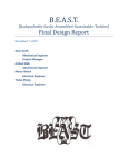
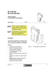
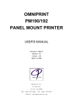
1
IB IL SGI 2/P-PAC Inline analog strain gauge input terminal, two precise inputs, 4, 6-wire connection method Data sheet 7647_en_04 1 © PHOENIX CONTACT 2013-01-17 Description The terminal is designed for use within an Inline station. Features This terminal provides a precision input module to connect weighing cells, force transducers, mass force transducers and comparable, based on the strain gauges. – – The strain gauges can be connected using 6 or 4-wire technology. – Thanks to a serial interface the measured value can be output – directly on a weight display. There are two options for data exchange: – – Via process data – Via PCP (both inputs in the "Analog Values" PCP object) – The measured values are represented by standardized 16-bit – values. – – – – – Two high-precision inputs for the strain gauges Measuring ranges adjusted with nominal characteristic values upon delivery ±1 mV/V, ±2 mV/V, ±3 mV/V, ±3.33 mV/V, ±4 mV/V and ±5 mV/V Path adjustment in the process environment Connection of the strain gauges with 6- and 4-wire technology Sensor supply voltage provided by the terminal, no external power supply required For each channel: Low-resistance, floating N/O contact for the 80% calibration (shunt calibration) Serial interface for external weight displays Channels are configured independently of one another using the bus system. Tare weight adjustment Status message when zero point is reached and resting of measured value Diagnostic indicators Hardware version 01 or later: Approved for use in zone 2 potentially explosive areas WARNING: Explosion hazard when used in potentially explosive areas When using the terminal in potentially explosive areas, observe the corresponding notes. This data sheet is only valid in association with the IL SYS INST UM E user manual. Make sure you always use the latest documentation. It can be downloaded from the product at www.phoenixcontact.net/products. IB IL SGI 2/P-PAC 2 Table of contents 1 Description .............................................................................................................................. 1 2 Table of contents ..................................................................................................................... 2 3 Ordering data .......................................................................................................................... 3 4 Technical data ......................................................................................................................... 4 5 Additional tables ...................................................................................................................... 7 6 Internal circuit diagram ............................................................................................................ 8 7 Local diagnostic indicators ...................................................................................................... 9 8 Terminal point assignment..................................................................................................... 10 9 Electrical isolation.................................................................................................................. 10 10 Installation instructions .......................................................................................................... 10 11 Connection notes .................................................................................................................. 11 12 Notes on using the terminal block in potentially explosive areas ........................................... 12 13 Connection examples ............................................................................................................ 13 14 Display devices ..................................................................................................................... 15 15 Configuration ......................................................................................................................... 17 16 Process data.......................................................................................................................... 17 17 OUT process data words....................................................................................................... 17 18 Process data input words IN .................................................................................................. 19 19 PCP communication .............................................................................................................. 21 20 PCP object description .......................................................................................................... 22 21 PCP mode error messages.................................................................................................... 28 22 Startup and measuring jumper detuning................................................................................ 28 7647_en_04 PHOENIX CONTACT 2 IB IL SGI 2/P-PAC 3 Ordering data Description Order No. Pcs. / Pkt. Inline analog strain gauge input terminal, complete with accessories (con- IB IL SGI 2/P-PAC nector and labeling field), two precise inputs, 4, 6-conductor connection method Type 2884907 1 Accessories Type Order No. Pcs. / Pkt. Inline shield connector (Plug/Adapter) IB IL SCN-6 SHIELD 2726353 5 Connector, for digital 1, 2 or 8-channel Inline terminals (Plug/Adapter) IB IL SCN-8 2726337 10 Labeling field, width: 12.2 mm (Marking) IB IL FIELD 2 2727501 10 Insert strip, Sheet, white, Unlabeled, Can be labeled with: Office-Drucksys- ESL 62X10 teme, Plotter: Laser printer, Mounting type: Insert, Lettering field: 62 x 10 mm (Marking) 0809492 1 Shield connection clamp, for shield on busbars, contact resistance < 1 mOhm (Assembly) SK 8 3025163 10 Shield connection clamp, for shield on busbars, contact resistance < 1 mOhm (Assembly) SK 14 3025176 10 Shield connection clamp, for shield on busbars, contact resistance < 1 mOhm (Assembly) SK 20 3025189 10 Shield connection clamp, for shield on busbars, contact resistance < 1 mOhm (Assembly) SK 35 3026463 10 Support for busbars (Assembly) AB-SK 3025341 10 Support, Length: 95.5 mm, Width: 6.2 mm, Color: gray (Assembly) AB-SK 65 3026489 10 Support, Length: 10 mm, Width: 56 mm, Height: 20 mm, Color: silver (Assembly) AB-SK/E 3026476 10 PEN conductor busbar, 3mm x 10 mm, length: 1000 mm (Assembly) NLS-CU 3/10 SN 1000MM 0402174 10 Power terminal block, Connection method Screw connection, Load current : 41 A, Cross section: 0.5 mm² - 6 mm², Width: 7 mm, Color: silver AK 4 0404017 50 Connection terminal block, Connection method Screw connection, Load current : 41 A, Cross section: 0.5 mm² - 6 mm², Width: 7 mm, Color: green-yellow AKG 4 GNYE 0421029 50 Connection terminal block, Connection method Screw connection, Load AKG 4 BK current : 41 A, Cross section: 0.5 mm² - 6 mm², Width: 7 mm, Color: black 0421032 50 Software CD for FDT container for integrating device DTMs (free download) AX+ BASIC 2985068 1 DTM library AX DTM LIB 2988065 1 Documentation Type Order No. Pcs. / Pkt. User manual, English, Automation terminals of the Inline product range IL SYS INST UM E - - Application note, English, Inline terminals for use in zone 2 potentially explosive areas AH EN IL EX ZONE 2 - - User manual, English, for the Peripherals Communication Protocol (PCP), only available as a download. IBS SYS PCP G4 UM E 2745169 1 User manual, English, Porting using PCP compact IBS PCP COMPACT UM E - - 7647_en_04 PHOENIX CONTACT 3 IB IL SGI 2/P-PAC 4 Technical data Dimensions (nominal sizes in mm) 135 71,5 119,8 Width 48.8 mm Height 136 mm Depth 71.5 mm General data Color green Weight 220 g Operating mode Process data operation with 3 words, PCP with 1 word Ambient temperature (operation) -25 °C ... 55 °C Ambient temperature (storage/transport) -25 °C ... 85 °C Permissible humidity (operation) 10 % ... 95 % (according to DIN EN 61131-2) Permissible humidity (storage/transport) 10 % ... 95 % (according to DIN EN 61131-2) Air pressure (operation) 70 kPa ... 106 kPa (up to 3000 m above sea level) Air pressure (storage/transport) 70 kPa ... 106 kPa (up to 3000 m above sea level) Degree of protection IP20 Protection class III, IEC 61140, EN 61140, VDE 0140-1 Connection data Inline connectors Connection method Spring-cage connection Conductor cross section, solid 0.08 mm² ... 1.5 mm² Conductor cross section, stranded 0.08 mm² ... 1.5 mm² Conductor cross section [AWG] 28 ... 16 Interface Inline local bus Connection method Inline data jumper Transmission speed 500 kBit/s Transmission physics Copper Inline potential routing / Power consumption Communications power UL 7.5 V DC Current consumption from UL max. 100 mA, typ. 85 mA 7647_en_04 PHOENIX CONTACT 4 IB IL SGI 2/P-PAC Inline potential routing / Power consumption I/O supply voltage UANA 24 V DC Current consumption from UANA max. 100 mA 25 mA (in case of typical load of 350 Ohm per channel) 7 mA (for no-load operation without strain gauge or display) 80 mA (For a maximum load of 55 Ω and display) Power consumption Typ. 1.2 W (Device in nominal operation) max. 3.2 W (Device with maximum load) Voltage output Number of outputs 2 Impedance > 55 Ω (per channel) Output voltage typ. 5 V Output current max. 90 mA (per channel) Short-circuit protection of the voltage outputs Yes, at least 1 minute through temperature monitoring Floating N/O contact Quantity 2 (Ka1-Kb1, Ka2-Kb2) Volume resistance < 1 Ω (typical) Volume resistance 5 Ω (maximum) Typical response time 100 ms (typical) Serial interface Name V.24 (RS-485) serial interface Network Yes Addressing Address 1 = Measured gross/net value Address 2 = Measured tare value Termination resistor 120 Ω Transmission protocol STX/ETX Input channels for strain gauge Number of inputs 2 Connection method 6 or 4-wire, twisted pair shielded cable Characteristics ±1 mV/V, ±2 mV/V, ±3 mV/V, ±3.33 mV/V, ±4 mV/V, ±5 mV/V Bridge difference Ud Measuring range specified by selecting the characteristic Bridge voltage U0 5V Measured value representation 15 bits + sign bit (process data); 15 bits + sign bit and measured display value in the ASCII character set (PCP) Process data update typ. 100 ms (12.5 ms, depends on the configuration) Resolution A/D 24 bit A/D conversion time Typ. 100 ms (12.5 ms, depends on the configuration) Averaging Can be parameterized: None or using 4,16 or 32 measured values; default setting: using 16 measured values Limit frequency 0.3 Hz (with default setting) Programming Data ID code (hex) DF ID code (dec.) 223 Length code (hex) 03 Length code (dec.) 03 Process data channel 48 Bit Input address area 6 Byte 7647_en_04 PHOENIX CONTACT 5 IB IL SGI 2/P-PAC Programming Data Output address area 6 Byte Parameter channel (PCP) 2 Byte Register length (bus) 64 Bit PROFIBUS telegram data Required parameter data 23 Byte Need for configuration data 5 Byte Error messages to the higher level control or computer system Failure of the power supply at UANA Error message in the process data Failure of or insufficient communications power UL I/O error message sent to the bus coupler Peripheral fault Error message in the process data Electrical isolation/isolation of the voltage areas Logic/analog I/O (digital isolator) 500 V AC, 50 Hz, 1 min RS-485/analog I/O (isolating distance) 500 V AC, 50 Hz, 1 min N/O contact Ka1 - Kb1 / analog I/O (isolating distance) 500 V AC, 50 Hz, 1 min N/O contact Ka2 - Kb2 / analog I/O (isolating distance) 500 V AC, 50 Hz, 1 min Functional earth ground/analog I/O (isolating distance) 500 V AC, 50 Hz, 1 min Logic/RS-485 (digital isolator) 500 V AC, 50 Hz, 1 min N/O contact Ka1 - Kb1 / RS-485 (isolating distance) 500 V AC, 50 Hz, 1 min N/O contact Ka2 - Kb2 / RS-485 (isolating distance) 500 V AC, 50 Hz, 1 min Functional earth ground/RS-485 (isolating distance) 500 V AC, 50 Hz, 1 min Logic / N/O contact Ka1 - Kb1 (optocoupler) 500 V AC, 50 Hz, 1 min N/O contact Ka2 - Kb2/N/O contact Ka1 - Kb1 (isolating distance) 500 V AC, 50 Hz, 1 min Functional earth ground / N/O contact Ka1 - Kb1 (isolating distance) 500 V AC, 50 Hz, 1 min Logic / N/O contact Ka2 - Kb2 (optocoupler) 500 V AC, 50 Hz, 1 min Functional earth ground / N/O contact Ka2 - Kb2 (isolating distance) 500 V AC, 50 Hz, 1 min Logic/functional earth ground (isolating distance) 500 V AC, 50 Hz, 1 min Approvals For the latest approvals, please visit www.phoenixcontact.net/products. 7647_en_04 PHOENIX CONTACT 6 IB IL SGI 2/P-PAC 5 Additional tables Tolerances at TA = 25°C Nominal characteristic value ±1 mV/V, ±2 mV/V, ±3 mV/V, ±3.33 mV/V, ±4 mV/V, ±5 mV/V Temperature and drift response (TA = -25°C ... +55°C) Relative deviation in % related to the measuring range final value Typical Maximum ±0.01% ±0.05% Relative drift in ppm/K related to the measuring range final value Typical Maximum ±1 mV/V, ±2 mV/V, ±3 mV/V, ±3.33 mV/V, ±4 mV/V, ±5 mV/V 5 ppm/K 15 ppm/K The typical values contain the typical offset error, gain error and linearity error in the respective configuration related to the positive measuring range up to 100% of the nominal characteristic value. The typical value contain the typical offset value and gain value in the respective configuration in the temperature range from -25°C up to +55°C related to the positive measuring range up to 100% of the nominal characteristic value. This data is valid for nominal operation (preferred mounting position, US= 24 V) with a conversion time of 100 ms and a 16-sample average value. This data is valid for nominal operation (preferred mounting position, US= 24 V) with a conversion time of 100 ms and a 16-sample average value. The maximum tolerance values represent the worst case measurement inaccuracy. Besides the maximum offset error, the gain error and the linearity error, the maximum tolerance values also comprise the longtime drift as well as the maximum tolerances of the test and calibration equipment. The maximum tolerance values represent the worst case measurement inaccuracy. Besides maximum offset and gain drift, they also comprise longtime drift as well as the maximum tolerances of the test and calibration equipment. Please also observe the values for temperature drift and the tolerances under influences of electromagnetic interferences. Additional tolerances influenced by electromagnetic fields Type of electromagnetic interference Typical deviation in % related to the measuring range final value Electromagnetic fields; field strength 10 V/m according to EN 61000-4-3/ IEC 61000-4-3 < ±0.1% Conducted interference, Class 3 (10 V test voltage) according to EN 61000-4-6/IEC 61000-4-6 - Fast transients (burst) up to an interference voltage of ±2.2 kV in acc. with EN 61000-4-4 / IEC 61000-4-4 - The values refer to nominal operation with default settings. 7647_en_04 PHOENIX CONTACT 7 IB IL SGI 2/P-PAC 6 Internal circuit diagram Local bus OPC SRE 1 UL+ UANA UL– Level Adaptation 3V/5V Supervisor 24 V µC GNDUV +5V +5V GNDUV +24 V (US) GNDUV Tx– +UV1 +UV2 +U01 –U01 +Ud1 –Ud1 Ka1 +24 V (UM) Figure 1 Tx+ GNDTxD Kb1 +U02 –U02 +Ud2 –Ud2 Ka2 Kb2 Internal wiring of the terminal points Key: Low pass filter Protocol chip OPC Register expansion DC/DC converter XXX SRE 1 XXX Level adaptation Level Adaptation 3V/5V DC/DC converter with electrical isolation XXX XXX Hardware monitoring RS-485 interface with electrical isolation Supervisor Microprocessor Photomos relay µC Optocoupler with bipolar buffer Electrically isolated area Analog/digital converter Explanation for other used symbols has been provided in the IL SYS INST UM E user manual. 7647_en_04 PHOENIX CONTACT 8 IB IL SGI 2/P-PAC 7 Local diagnostic indicators D SGI 2/P TR CH1 CH2 Note regarding open circuit message During power up or configuration the system does not detect whether a sensor is connected or if a cable break has occurred (all cables disconnected) due to the measuring principle. In this case, you will not obtain any valid data. As such, take the time to ensure that the sensor is fully connected. If an open circuit message is output, first remove the cause prior to resetting the message. If you do not remove the cause of the open circuit message and perform a voltage reset or configure the module, the module itself will behave according to the following table. D 1 CH SGI 2/P TR 2 CH Open circuit message triggered by No sensor connected/cable break Defective sensor cable (GNDUv, +U0, -U0, +Ud, -Ud) Figure 2 Behavior following voltage reset or configuration Malfunction not detected and not reported Malfunction is detected and reported Local diagnostic indicators Function identification Designation D TR CH 1 CH 2 Color Meaning Green green green green Green ON green OFF Diagnostics (bus and logic voltage) PCP communication Diagnostics of channel 1 Channel 1 is OK Channel 1 not connected or not supplied or open circuit green Diagnostics of channel 2 Green ON Channel 2 is OK green OFF Channel 2 not connected or not supplied or open circuit An open circuit is detected according to the following table: Faulty sensor cable +UV GNDUv +U0 -U0 +Ud -Ud 7647_en_04 Open-circuit message in diagnostics No Yes Yes Yes Yes Yes PHOENIX CONTACT 9 IB IL SGI 2/P-PAC 8 Terminal point assignment No definition is available for the designations of sensor cables. For this reason, the designations used in data sheets may deviate from those used by sensor manufacturers. Examples: Bridge voltage U0x = sense input US Bridge difference Udx = signal or output 1 1 1.1 1.2 1.3 1.4 1.1 2 1 2 1 2.1 1 2.1 1.2 2 2 2.2 2 2 2.2 1.3 3 3 2.3 3 3 2.3 1.4 4 4 2.4 4 2.4 1 4 9 Electrical isolation Logic area (microprocessor, protocol chip, bus interface) Local bus (IN) UL (7.5 V DC) Local bus (OUT) UL (7.5 V DC) UANA (24 V DC) Terminal point assignment RS–485 Assignment A B Electrical isolation between area A and B Terminal point Connector 1 1.1 / 2.1 1.2 / 2.2 1.3 / 2.3 1.4 / 2.4 Connector 2 1.1 / 2.1 1.2 / 2.2 +UV1/GNDUv +U01/-U01 +Ud1/-Ud1 FE Jumper supply UV1 Jumper voltage U01 Jumper difference Ud1 Shield connection Tx+ / TxGNDTx 1.3 / 2.3 Ka1/Kb1 1.4 / 2.4 Connector 3 1.1 / 2.1 1.2 / 2.2 1.3 / 2.3 1.4 / 2.4 Connector 4 1.1 / 2.1 1.2 / 2.2 1.3 / 2.3 FE RS-485 interface Reference potential of the 10 Installation instructions RS-485 interface N/O contact for shunt cali- High current flowing through potential jumpers UM and US leads to a temperature rise in the potential jumpers and inside bration of channel 1 the terminal. To keep the current flowing through the potential Shield connection jumpers of the analog terminals as low as possible, always place the analog terminals after all the other terminals at the Jumper supply UV2 end of the main circuit (for the sequence of the Inline termiJumper voltage U02 nals: see also IL SYS INST UM E user manual). Jumper difference Ud2 Shield connection Ka2/Kb2 1.4 / 2.4 FE 7647_en_04 Signal Analog I/O N/O contact Ka2–Kb2 Figure 3 N/O contact Ka1–Kb1 UANA (24 V DC) FE potential Jumper supply +UV2/GNDUv +U02/-U02 +Ud2/-Ud2 FE Figure 4 Analog inputs RS-485 N/O contact Ka–Kb Electrical isolation of the individual function areas Not used Not used N/O contact for shunt calibration of channel 2 Shield connection PHOENIX CONTACT 10 IB IL SGI 2/P-PAC 11 Connection notes Connecting the strain gauges Connect the strain gauges using shielded twisted pair cables. Connecting the shield Only connect the shield at one point, preferably at the terminal. If the shield is securely connected to the sensor, insulate the shield on the terminal side. Unused channels If a channel (connector 1 or connector 3) is not used, connect the following terminal points on this connector with each other: 1.1, 1.2 and 1.3 as well as 2.1, 2.2 and 2.3. Figure 5 7647_en_04 1.1 2.1 1.2 2.2 1.3 2.3 1.4 2.4 Jumpering the terminal points of unused channels PHOENIX CONTACT 11 IB IL SGI 2/P-PAC 12 Notes on using the terminal block in potentially explosive areas WARNING: Explosion hazard Installation in zone 2 1. 2. Please make sure that the following notes and instructions are observed. 3. Approval according to EC directive 94/9/EC II 3 G Ex nA IIC T4 Gc X Installation notes 1. 2. 3. 4. 5. 6. 7. 8. 9. 4. Observe the specified conditions for use in potentially explosive areas. Install the device in a suitable approved housing (with at least IP54 degree of protection) that meets the requirements of EN 60079-15. Observe the requirements of EN 60079-14. In potentially explosive areas, the Inline terminal may only be snapped on or off and cables may only be connected when the power is switched off. In zone 2, only connect devices to the supply and signal circuits that are suitable for operation in potentially explosive areas of zone 2 and the conditions at the installation location. This Inline terminal is a category 3 device and is suitable for installation in the potentially explosive areas of zone 2. Restrictions/limit values The device meets the requirements of EN 60079-0:2009 1. Only Inline terminals that are approved for use in poand EN 60079-15:2010. tentially explosive areas may be assembled on this The Inline terminal must only be installed, operated, and Inline terminal. maintained by qualified personnel. Before using an Inline terminal in a zone 2 potentially exPlease follow the installation instructions given in the plosive area, check whether it has been approved for inIL SYS INST UM E user manual and the package slip. stallation within this area. For a list of terminals that are approved for the potentially When installing and operating the device, the applicable explosive areas of zone 2, please refer to the AH EN IL safety directives (including national safety directives), acEX ZONE 2 application note. cident prevention regulations, as well as general technical regulations, must be observed. 2. The maximum permissible current for each tension spring contact is 2 A. Please refer to the corresponding documentation (user manual, data sheet, package slip) and the certificates (declaration of conformity and other approvals, if applicable) for safety-related data. Access to the circuits inside the Inline terminal is not permitted. Do not repair the Inline terminal by yourself but replace it with a terminal of the same type. Repairs may only be performed by the manufacturer. The manufacturer is not liable for damage resulting from noncompliance. The IP20 degree of protection (EN 60529) of the device is intended for a clean and dry environment. Do not subject the Inline terminal to mechanical strain and/or thermal loads, which exceed the limits specified in the product documentation. The Inline terminal has not been designed for use in potentially dust-explosive atmospheres. 7647_en_04 PHOENIX CONTACT 12 IB IL SGI 2/P-PAC 13 Connection examples 13.1 6-wire connection (a strain gauge load cell per channel) with two indicators The RS-485 interface has bus capability and can operate several devices. When an address is selected, the current measured value of channel 1 or channel 2 can be displayed. Use a twisted-pair, shared and shielded data line to connect the displays. Fit a termination resistor to the data cable at the most remote point of the RS-485 network. Use the integrated termination resistors of the display for this purpose. 1 S102 Address 1 S302 Address 2 D CH1 CH2 SGI 2/P TR 2 Rx+ Rx- ZR COM Rx+ Rx- ZR COM +Uv1 GNDUv Tx+ Tx- +U01 -U01 GNDTxGNDTx +Ud1 -Ud1 FE RL Figure 6 Key: RL: Address 1: Address 2: FE Ka1 Kb1 FE FE RL Connection of strain gauges in 6-wire technology Cable resistance Displays the measured value of channel 1 Displays the measured value of channel 2 The RS-485 interface transmits a special weighing protocol. 7647_en_04 PHOENIX CONTACT 13 IB IL SGI 2/P-PAC 6-wire connection (several strain gauge load cells per channel) Each channel can supply a current of up to 90 mA. For instance, 6 load cells with a basic resistance of 350 Ω may be connected in parallel. 13.3 4-wire connection with a shunt resistor The following figure shows the connection of a resistive pressure sensor with an 80% calibration. This sensor is typically used for injection molding of plastics. 1 Connector 1 Channel 1 Strain gauge 1 RL D TR 1.1 2.1 1.2 2.2 1.3 2.3 1.4 2.4 2 CH1 CH2 SGI 2/P 13.2 R R Ud U0 UV +UV +U0 +Ud GNDUv Tx+ +U01 -U01 GNDTx GNDTx +Ud1 -Ud1 Ka1 Kb1 FE FE FE FE Tx- -Ud -U0 GNDUV FE R +Uv1 R RL Strain gauge 2 RL R R Ud U0 UV Distribution R R RL Strain gauge n R RL RL RL R Ud U0 UV R R RCAL RL Figure 7 Key: RL: Figure 8 Connection of several strain gauges in 6-wire technology Key: RL: Connection of strain gauges in 4-wire technology with a shunt resistor Cable resistance Cable resistance Channel 1/channel 2: Strain gauges can also be connected to the terminal in 4-wire technology. In this case connect +UV with +U0 and GNDUv with -U0. There is no temperature and long-term drift compensation for the connecting cable in 4-wire technology. 7647_en_04 PHOENIX CONTACT 14 IB IL SGI 2/P-PAC 14 Display devices A digital display from Siebert Industrieelektronik GmbH may Ordering types are, for example: be connected to the RS-485 interface of the terminal (see fol- – Character height: 14 mm, 57 mm, 100 mm, 160 mm, or lowing table). 250 mm – Character color: Red, white, green Siebert Industrieelektronik GmbH Siebertstrasse, 66571 Eppelborn, Germany – Display: Single or double-sided Postfach 1180, 66571 Eppelborn, Germany – Dimension symbols (fixed on strips, specify when ordering): Phone: +49 (0) 6806/980-0 F101 for g, F102 for kg, F103 for t Fax: +49 (0) 6806/980-999 – Degree of protection: IP40, IP54, IP65 Internet: www.siebert.de – Assembly: Panel, wall and suspended mounting E-mail: [email protected] – Operating voltage: 24 V DC, 230 V DC – ... Please contact Siebert Industrieelektronik GmbH for further information or ordering types. Feature Digital display S102 for panel mounting Order designation S102-W6/14/0R-000/0B-SL with dimension symbol F102 Large size display S302 for indoor installation S302-F6/10/0R-100/0A-SL with dimension symbol F102 Dimensions (W x H x D) Character height Reading distance Character color 96 mm x 48 mm x 70 mm 870 mm x 245 mm x 145 mm Large size display S302 for outdoor installation S302-F6/10/0R-114/0A-SL with dimension symbol F102 and weather protection hood -1011 870 mm x 245 mm x 145 mm 14 mm Bright red LED display 100 mm Up to 40 m Red "super bright" LED display for outdoors 6 digits, single-sided kg (F102) Serial (RS-485) IP54 with climate compensation, heating and weather protection hood Wall mounting, cable entry at bottom 230 V AC Steel sheet housing, double-layer painting Display Dimension symbol Interface Degree of protection 6 digits kg (F102) 100 mm Up to 40 m Bright red LED display for indoors 6 digits, single-sided kg (F102) Serial (RS-485) IP40 Serial (RS-485) IP54 Assembly Panel mounting Wall mounting, cable entry at bottom 230 V AC Operating voltage 24 V DC Other 7647_en_04 PHOENIX CONTACT 15 IB IL SGI 2/P-PAC Connector pin assignment of the displays NET TARA -0- 1 2 For the connector pin assignment of the displays, please refer to the documentation of the displays. 44/42,5 48 Display dimensions 3 kg Measured value representation on the display 96 NET TARA -0- 1 2 3 kg 8 2...6 M Ca. 70 90 Figure 11 Figure 9 Dimensions of display S102 ... (dimensions in mm) Example of a display LEDs on the display Designation NET M: Menu button Panel cutout 92 mm x 45 mm 245 kg TARA -0>< 1 2 3 Meaning Net, LED lights up after a tare weight adjustment Not supported Zero point reached Standstill reached Channel 1 Channel 2 Not supported The display is updated every 500 ms. 70 70 70 145 Ø7 16 870 16 Figure 10 7647_en_04 Dimensions of display S302 ... (dimensions in mm) PHOENIX CONTACT 16 IB IL SGI 2/P-PAC 15 Configuration 16 Process data Terminal configuration is only required if at least one of the channels is to be operated outside the default values. The terminal occupies three process data words and one PCP word. You can configure the terminal either using process data or using PCP and transmit the analog values accordingly. Order of the process data words: For easy terminal configuration a function block can be downloaded at www.phoenixcontact.net/products OUT0 (control word) OUT1 OUT2 IN0 (status word) IN1 IN2 The configuration options differ for configuration using process data (PD) and configuration using PCP. 17 The following configurations are possible: Configuration Short desig- Default nation Selection of Mean-value 16-sample mean-value genmean-value eration Conversion time Conversion 100 ms of the A/D con- time verter Nominal charac- Nominal ±2 mV/V teristic value of characteristhe connected tic value sensor Nominal load of Nominal load 0 the connected sensor Adjustment Adjustment 0 value of the con- value nected sensor 7647_en_04 PD X OUT process data words PCP Three OUT process data words are available. The terminal is configured using the OUT process data words. X Where: X X X X – – – Output word OUT0 contains the command Output word OUT1 contains the parameters for channel 1 Output word OUT2 contains the parameters for channel 2 Configuration errors are indicated in the status word. The configuration settings are stored in a volatile memory. If you change the configuration, the message "Measured value invalid" appears (diagnostic code 8004hex), until new measured values are available. - X - X PHOENIX CONTACT 17 IB IL SGI 2/P-PAC 17.1 Output word OUT0 (control word) Bit Assignment 15 ... 8 Command code OUT0 7 6 5 4 3 2 1 0 0 0 0 0 0 0 0 0 Bit 15 to bit 8 (command code): Bit 15 ... 8 00000000 0001000C OUT0 [hex] 0000 1x00 00110000 3000 00110001 3100 00110010 3200 00110011 3300 00111100 3C00 01000000 4000 Command function Reading measured values Read configuration in IN1 channel-by-channel. C = Channel number; 0 = Channel 1, 1 = Channel 2) Read minimum value; IN1: Minimum value channel 1 IN2: Minimum value channel 2 Read maximum value; IN1: Maximum value channel 1, IN2: Maximum value channel 2 Delete minimum and maximum value of channel 1 Delete minimum and maximum value of channel 2 Read firmware version and module ID in IN1. Configure device; configuration for channel 1 in OUT1 and for channel 2 in OUT2 17.2 Output words OUT1 and OUT2 (parameter words) For command 4000hex the parameters must be specified in OUT1 and OUT2. This parameter word is only evaluated for this command. OUT1 and OUT2 Bit 15 14 13 12 11 10 9 8 7 6 5 4 3 2 1 0 Assign- 0 0 0 0 0 0 M 0 0 0 W N ment Where: M Mean-value W Conversion time Nominal characteristic value N Selects mean-value generation. After every conversion, the measured value is saved in a mean-value memory via which the mean-value is generated. The memory size can be selected with the mean-value option. E.g., for a 16sample mean-value, the mean-value is generated using the last 16 measured values. Conversion time of the analog/digital converter Selects the measuring range Set all unused bits to 0. If invalid parameters are specified in the parameter word, the command will not be executed. The command is acknowledged in the input words with the set error bit. During the transient response (e.g., following a configuration command), the fluctuating measured values may exceed the minimum and maximum values. Therefore, at the start of acquisition delete the minimum and maximum values using command 3200hex and/or 3300hex. The minimum value is set to the largest positive number (7FFhex = 32767dec) when deleting. The maximum value is set to the largest negative number (8000hex = -32768dec). 7647_en_04 PHOENIX CONTACT 18 IB IL SGI 2/P-PAC Parameters for configuration 18 Process data input words IN 18.1 Input word IN0 (status word) The values displayed in bold are pre-settings. Bits 10 to 9: Input word IN0 performs the task of a status word. Code dec 0 1 2 3 M: Mean-value bin 00 01 10 11 Bit Assignment 16-sample mean-value No mean-value 4-sample mean-value 32-sample mean-value IN0 15 14 ... 8 EB SP 7 6 5 4 3 2 1 0 0 0 0 0 0 0 0 0 EB: Error Bit Bit 4: Code dec 0 1 bin 0 1 C: Conversion time of the analog-digital converter bin 0000 0001 0010 0011 0100 0101 No error has occurred. An error has occurred. 100 ms 12.5 ms The error bit indicates whether a command could be executed without errors or not. N: Nominal specific value For the command code 4000hex (configure device), a set error bit indicates an invalid configuration. Possible reasons: – At least one of reserved bits is set. – An invalid value was specified for the nominal characteristic value. Bit 3 to bit 0: Code dec 0 1 2 3 4 5 Other EB = 0 EB = 1 ±1 mV/V ±2 mV/V ±3 mV/V ±3.33 mV/V ±4 mV/V ±5 mV/V Invalid For the command code 0000hex (read measured values), the error bit indicates a group error message. When the error bit is set, there is an error message on one or both channels. Mirrored command code: A command code mirrored from the control word. Here, the MSB is suppressed. Step response and limit frequencies The following table specifies the time for the step response and the limit frequency depending on the settings for conversion time and mean-value. Conver- Meansion time value 100 ms 100 ms 100 ms 100 ms 12.5 ms 12.5 ms 12.5 ms 12.5 ms 7647_en_04 Step response from 0% to 100% (typical) 32-sample 3.4 s 16-sam- 1.8 s ple 4-sample 600 ms None 200 ms 32-sample 425 ms 16-sample 225 ms 4-sample 75 ms None 25 ms Limit frequency (typical) 0.15 Hz 0.3 Hz 1 Hz 2.5 Hz 1 Hz 2.5 Hz 10 Hz 20 Hz PHOENIX CONTACT 19 IB IL SGI 2/P-PAC 18.2 Input words IN1 and IN2 The measured values, configuration or firmware version are transmitted to the controller board or the PC via process data input words IN1 an IN2 according to the configuration. For control word 3C00hex, IN1 provides the firmware version and the module ID. The module ID for the terminal is 3hex. Example: Firmware version 1.23 An open circuit is detected according to the following table: Faulty sensor cable +UV GNDUv +U0 -U0 +Ud -Ud Open-circuit message in diagnostics No Yes Yes Yes Yes Yes IN1 Please observe the notes regarding open cirBit 15 14 13 12 11 10 9 8 7 6 5 4 3 2 1 0 cuit message under "Local diagnostic indicaAssign1 2 3 3 tors" ment (hex) Meaning Firmware version 1.23 Mod- Typical measured values: ule ID Detuning in % of Input word [hex] Input word [dec] nominal value Measured values [%] The measured values are available in IB IL format. > 130.048 8001 Overrange The measured value is represented in bits 14 to 0. An addi+130.048 7F00 32512 tional bit (bit 15) is available as a sign bit. +100.000 61A8 25000 00FA 250 15 14 13 12 11 10 9 8 7 6 5 4 3 2 1 0 +1.000 +0.004 0001 1 SB Analog value 0.0 0000 0 -0.004 FFFF -1 Bit 15: Most significant bit (MSB) -100.000 9E58 -25000 Bit 0: Least significant bit (LSB) -130.048 8100 -32512 SB Sign bit < -130.048 8080 Underrange The IB IL format supports extended diagnostics. 8002 Open circuit Values >8000hex and <8100hex indicate an error. To calculate the detuning as a percentage for other measured The following diagnostic codes are possible: values, please use the following formula: Code (hex) Error Detuning = Process data value * 0.004 or 8001 Measuring range exceeded (overrange) Detuning = Process data value/250 8002 Open circuit Example: 8004 Measured value invalid/no valid measured value available Nominal characteristic value ±2 mV/V 8020 Faulty supply voltage Process data value 10000dec 8040 Device faulty 8080 Below measuring range (underrange) Detuning = 10000/250 =40% 40% of 2 mV/V = 0.8 mV/V 7647_en_04 PHOENIX CONTACT 20 IB IL SGI 2/P-PAC 19 PCP communication 19.1 General information The programs IBS CMD (for standard controller boards) and PC WorX (for Controllers (ILC), Field Controllers (FC) and Remote Field Controllers (RFC)) are available for the configuration and parameterization of your INTERBUS system. For additional information, please refer to the documentation of the software used. For information on PCP communication, please refer to the PCP user manuals (see Ordering data). By default upon delivery, the terminal is configured according to the default settings (under configuration). The terminal can be configured using process data or PCP to suit your application. In PCP mode, the terminal is configured with the "Config Table" object. 19.2 Object dictionary for PCP communication Index 0080hex 0081hex Data type Record Unsigned 16 A 2 2 L 8 2 0082hex Record 2 6 0083hex Record 2 6 0091hex Unsigned 8 2 1 0092hex Unsigned 8 2 1 0093hex 0097hex Unsigned 8 Var of Visible String Var of Visible String Unsigned 8 Record 2 1 0098hex 009Ahex 0018hex A L 7647_en_04 1 Meaning Terminal configuration Analog values of the channels Measured values in the extended float format Display value in the extended float format Dynamic control of tare weight adjustment Static control of path adjustment Status of the Inline terminal Display string of channel 1 1 2 6 1 Number of elements Length of an element in bytes Object name Config Table Analog Values Rights rd/wr rd Measured Value Float rd Display Value Float rd Control Dynamic wr Control Static wr Status Display String Channel 1 rd rd Display string of channel 2 Display String Channel 2 rd Reset to default settings Diagnostics Default Setting Diag State wr rd rd wr Read access permitted Write access permitted PHOENIX CONTACT 21 IB IL SGI 2/P-PAC 20 PCP object description 20.1 "Config Table" object Configure the terminal using this object. Object description: Object Access Data type Index Subindex Length (bytes) Data Config Table Read, write Array of Records 2 x 8 bytes Record = 4 x Unsigned 16 0080hex 00hex Write all elements Configuration of channel 1 01hex Nominal load (MAX) of channel 1 Adjustment value of channel 1 Reserved Configuration of channel 2 02hex Nominal load (MAX) of channel 2 Adjustment value of channel 2 Reserved Subindex 00hex 10hex 08hex Subindex 01hex to 02hex Terminal configuration Element value range Adjustment value element: Value range: Default value: 0 ... 32767dec 0 Please note for the "Nominal load (MAX)" element: If MAX = 0, no value is output on the display of the channel. MAX dimensions the maximum value of the display and the display format. Nominal load (MAX) 1 ... 9 10 ... 99 100 ... 999 1000 ... 9999 10000 ... 65535 Display format 1.2345 12.345 123.45 1234.5 12345 MAX corresponds to a detuning of 100%. The use of MAX provides for the maximum value of a sensor to be input. Example: Sensor with 1 mV/V and MAX = 50 kg. Configuration of the terminal with MAX = 50dec. Then the display corresponds directly to the measured weight in kg. Jumper difference 0.5 mV/V 1.0 mV/V Process data value Display 12500dec -> 50% 25000dec -> 100% 25.000 50.000 The "Configuration channel x" elements have the following structure: If an invalid configuration is specified, a negative confirmation is generated with error message 08hex, 00hex or xx30hex. The OUT1 and OUT2 low byte of the Additional_Error_Code is 30hex (value is out of Bit 15 14 13 12 11 10 9 8 7 6 5 4 3 2 1 0 range), the high byte contains the number of the affected element. Assign- 0 0 0 0 0 M 0 0 0 0 W N Example: Config Table is completely written with data (subinment dex 00) and the entry for channel 2 is invalid. In this case, the Where: Additional_Error_Code is equal to 0230hex. M W N Mean-value Conversion time Nominal characteristic value Value range: Default value: See "Parameters for configuration" See "Parameters for configuration" Please note for the "Adjustment value" element: The value is specified as a percentage of MAX. An LSB corresponds to 0.004%. Example: Nominal load (MAX) element: Value range: Default value: 7647_en_04 0 ... 65535dec 0 Sensor with 50 kg nominal load (MAX). It should be adjusted to 25 kg. Then the adjustment value corresponds to 50% of MAX. Determine the adjustment value as follows: 50% / 0.004% = 12500. Therefore configure the adjustment value with 12500dec. PHOENIX CONTACT 22 IB IL SGI 2/P-PAC 20.2 "Analog Values" object The elements of this object contain the analog values of the channels in IB IL format. Object description: Object Access Data type Index Subindex Length (bytes) Data Analog Values Read Array of Unsigned 16 2 x 2 bytes 0081hex 00hex Read all elements Analog value of channel 1 01hex 02hex Analog value of channel 2 Subindex 00hex 04hex 02hex Subindex 01hex to 02hex Analog values of the channels 20.3 Extended Float Format for objects 0082hex and 0083hex The Extended Float Format is a specially defined format. It consists of the measured value in the float format, a status and a unit code. The construct is defined as a Record. Status is necessary because the float format defines no patterns providing information on the status of the numerical value. Status corresponds to the LSB of the Inline diagnostic codes (e.g. overrange: Status = 01, Inline diagnostic code = 8001hex). If Status = 0, the measured value is valid. Record structure: Element Data type 1 2 3 Length in Meaning bytes Float 4 Value in the float format acc. to IEEE 754 Unsigned 8 1 Status Unsigned 8 1 Unit code "Units Code" combines the ASCII characters of the "Config Table" in an 8-bit code. Code 57 (39hex) 61 (3Dhex) Unit Percentage (%) Kilograms (kg) Structure of the float format according to IEEE 754 in the bit representation: VEEE EEEE SB E M EMMM MMMM MMMM MMMM MMMM MMMM 1 sign bit, 0: positive, 1: negative 8 bits exponent with offset 7Fhex 23 bits mantissa Some example values for conversion from floating point to hexadecimal representation: Floating point 1.0 10.0 1.03965528 - 1.0 7647_en_04 Hexadecimal representation 3F 80 00 00 41 20 00 00 3F 85 13 6D BF 80 00 00 PHOENIX CONTACT 23 IB IL SGI 2/P-PAC 20.4 "Measured Value Float" object 20.6 "Control Dynamic" object The elements of this object contain the measured values in the highest accuracy of the terminal. The elements of this object are used for the tare weight adjustment. Object description: Object description: Object Access Data type Index Subindex Length (bytes) Data 20.5 Measured Value Float Read Array of Records 2 x 6 bytes 0082hex 00hex Read all elements Measured value of channel 1 01hex (Record) Measured value of channel 2 02hex (Record) Subindex 00hex 0Chex 06hex Subindex 01hex to 02hex Measured values in the extended float format "Display Value Float" object The elements of this object contain the display values of the channels in the highest accuracy of the terminal. Object Access Data type Index Subindex Control Dynamic Write Array of Unsigned 8 2 x 1 byte 0091hex 00hex Write all elements Channel 1 01hex 02hex Channel 2 Subindex 00hex 02hex 01hex Subindex 01hex to 02hex Control of tare weight adjustment; See below for the bit assignment Length (bytes) Data "Control Dynamic" for each channel Bit Assignment 7 0 6 0 5 0 4 0 3 0 2 0 1 0 0 Tare Value range: Object description: Object Access Data type Index Subindex Length (bytes) Data 7647_en_04 Display Value Float Read Array of Records 2 x 6 bytes 0083hex 00hex Read all elements 01hex Display value of channel 1 (Record) Display value of channel 2 02hex (Record) Subindex 00hex 0Chex 06hex Subindex 01hex to 02hex Display values of the channels in the extended float format Tare 0 1 No action Make a tare weight adjustment The tare value is not stored in the EEPROM. After power up, the value = 0. PHOENIX CONTACT 24 IB IL SGI 2/P-PAC 20.7 "Control Static" object 20.8 "Status" object The elements of this object are used for the path adjustment. The elements of this object contain the status of the status LEDs of the display as well as information about the default of Object description: the adjustment values. Object Access Data type Index Subindex Length (bytes) Data Object description: Control Static Write Array of Unsigned 8 2 x 1 byte 0092hex 00hex Write all elements 01hex Channel 1 Channel 2 02hex Subindex 00hex 02hex 01hex Subindex 01hex to 02hex Static control of path adjustment Object Access Data type Index Subindex Length (bytes) "Control Static" for each channel Bit Assignment 7 0 6 0 5 0 4 0 Status Read Array of Unsigned 8 2 x 1 byte 0093hex 00hex Read all elements Channel 1 01hex Channel 2 02hex 02hex Subindex 00hex 01hex Subindex 01hex to 02hex Status of the display LEDs and information about the default setting; see below for the bit assignment Data 3 Ka-Kb 2 J 1 N 0 0 "Status" of each channel Where: Ka-Kb J N N/O contact Ka-Kb Adjustment Zero point Bit Assignment 7 0 6 0 5 0 4 Def 3 0 2 NET 1 -0- 0 >< Value range: Value range: Def (Default) Ka-Kb Adjustment Zero point 0 1 0 1 0 1 Open N/O contact Ka-Kb Close N/O contact Ka-Kb No action Adjusting No action Determine zero point Do not carry out the actions "Adjustment" and "Determine zero point" at the same time. 0 1 NET, -0-, >< 0 1 The adjustment values of the path adjustment correspond to the default setting. The adjustment values of the path adjustment do not correspond to the default setting. LED OFF LED ON The bits NET, -0- and >< are only maintained when the display is active, i.e. the nominal load is unequal 0. The "Adjustment" and "Determine zero point" actions are used for the path adjustment. The values are stored in a nonvolatile way in the EEPROM. When there is an adjustment to be done and an adjustment value has not yet been determined with "Config Table", a negative Write Confirmation with the error message 08, 00, 0021hex is generated. This message means that the service cannot be executed at present. 7647_en_04 PHOENIX CONTACT 25 IB IL SGI 2/P-PAC 20.9 "Display String Channel 1" object The length of the read service depends on the number of The elements of this object contain the data flow of channel 1 characters to be transmitted. that is sent to the display. The six digits of the display are represented as ASCII characters, from 30hex (digit 0) to 39hex (digit 9). Object description: The decimal point is displayed with 2Chex. Object Access Data type Index Subindex Length (bytes) Data The LEDs are controlled with $S sequences. Display String Channel 1 Read Sequenc Character [hex] LED Var of Visible String 1 string e 0097hex $S1 24 53 31 1 00hex (Only access to all data pos- $S2 24 53 32 2 sible) $S3 24 53 33 3 (not supported) Amount of data present in the 00hex $S4 24 53 34 NET buffer $S5 24 53 35 TARA (not supported) : : $S6 24 53 36 -0Maximum length of the object xxhex $S7 24 53 37 >< Display value of channel 1 in the ASCII format Example: The value 32.645 is shown on the display, the rest LED and the 1 LED are on. This is shown by the following string: hex ASCII Display 20 33 3 3 32 2 2 2C . . 36 6 6 34 4 4 35 5 5 24 $ 53 S >< 37 7 24 $ 53 S LED 1 31 1 The leading 0 is not shown on the display. 7647_en_04 PHOENIX CONTACT 26 IB IL SGI 2/P-PAC 20.10 "Display String Channel 2" object 20.11 "Default Setting" object The elements of this object contain the data flow of channel 2 The adjustment values of the path adjustment are set individthat is sent to the display. ually or all together to the default setting with this object. Object description: Object Access Data type Index Subindex Length (bytes) Data Object description: Object Display String Channel 2 Access Read Data type Var of Visible String 1 string Index 0098hex 00hex (Only access to all data pos- Subindex sible) Amount of data present in the 00hex buffer Length : : (bytes) Maximum length of the object Data xxhex Display value of channel 2 in the ASCII format Default setting For a description, see "Display String Channel 1" object. Bit Assignment 7 0 Default Setting Write Array of Unsigned 8 2 x 1 byte 009Ahex 00hex Write all elements Channel 1 01hex 02hex Channel 2 Subindex 00hex 02hex 01hex Subindex 01hex to 02hex Reset to default settings 6 1 5 0 4 0 3 0 2 J 1 N 0 T Where: J N T Adjustment Zero point Tare Value range: Adjustment 0 1 Zero point 0 1 Tare 0 1 No action Set adjustment to default value (1.0) and store in EEPROM No action Set zero point to default value (0.0) and store in EEPROM No action Set tare to the default value (0.0) The value 4 (0100bin) in the high nibble should prevent that general values such as 00hex or FFhex execute a reset to default values. If the upper nibble is unequal 4 or the reserved bit 3 is set, a negative Write Confirmation with the error message 08,00, A020hex is generated. This message means that the service cannot be executed at present. 7647_en_04 PHOENIX CONTACT 27 IB IL SGI 2/P-PAC 20.12 "Diag State" object 21 PCP mode error messages The elements of this object are used for a structured message The terminal error messages have the parameters of an error. Error_Class = 8 (device-specific error) and Error_Code = 0 (no communication error). Object description: The exact error cause is indicated with the Additional Code. The low byte of the Additional Code specifies the error cause. Object Diag State The high byte of the Additional Code (xx) contains the number Access Read of the affected element. If several elements are affected, the Data type Record 6 highest number is given. Index 0018hex The following Additional Codes can occur on this terminal: Subindex 00hex Read all elements xx20hex Service cannot be executed at present. Error Number Unsigned 16 01hex xx21 Service cannot be executed at present. hex 02hex Priority Unsigned 8 Value out of range or reserved bits used xx30 hex Channel Unsigned 8 03hex Hardware fault 0000 hex Error code Unsigned 16 04 hex 05hex Length (bytes) Data More inforUnsigned 8 mation follows 06hex Text (10 char- Visible String acters) Subindex 00hex 11hex 02hex Subindex 01hex 01hex Subindex 02hex 01hex Subindex 03hex 02hex Subindex 04hex 01hex Subindex 05hex 0Ahex Subindex 06hex Diagnostic status Value range: Error Number 0 ... 65535dec Priority Error code = 0000hex Other Channel Error code = 0000hex Other Error code 0000hex 8910hex 8920hex 7710hex 5160hex 5010hex More infor00hex mation follows Text (10 char- Error code = 0000hex acters) Other 7647_en_04 Prio: 00hex Prio: 02hex Channel: 00hex 01hex or 02hex OK Overrange Underrange Line break Power fail Hardware fault For information on PCP communication, please refer to the PCP user manuals (see Ordering data). 22 Startup and measuring jumper detuning To start the terminal, proceed as follows: • Install the terminal within the Inline station. To do so, proceed as described in the package slip. vor. • Connect the strain gauge in 6 or 4-wire technology (see "Connection examples"). • Connect the voltage to the Inline station. This power up configures the terminal with the default values. • If you do not wish to operate the terminal with the default values, configure the terminal via process data or PCP. • Jumper detuning can now be measured. If a sensor is connected after power up, the corresponding channel must be configured. After the configuration the channel is ready for operation. Text: Status OK Error-specific PHOENIX CONTACT GmbH & Co. KG • 32823 Blomberg • Germany www.phoenixcontact.com 28