1
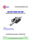
COAIRE
SCREW AIR COMPRESSORS
USER MANUAL
EXTROLLER
SERIAL NO. :
MODEL NO. :
CAUTION
For proper and safe use of the compressor, please follow all instructions and safety
precautions as identified in this manual, along with general safety regulations and
practices. Before installing and starting the compressor, read and understand this
manual
HSA-100S
All rights reserved
PART NO. CHSA-E07
DATE OF ISSUE: JANUARY, 2007
Printed in U.S.A.
COAIRE Technologies, Corporation
CONTENT:
1.0 General
Description...................................................................................................................................................... 3
1.1 Controller Model Variants........................................................................................................................... 3
1.2 General Operation ..................................................................................................................................... 4
2.0 I/O
Description...................................................................................................................................................... 5
2.1 Digital Inputs .............................................................................................................................................. 5
2.2 Digital Outputs ........................................................................................................................................... 6
2.3 Analogue Inputs and Outputs..................................................................................................................... 7
3.0 Machine State Diagram..................................................................................................................... 8
4.0 User Interface .................................................................................................................................... 11
4.1 Keypad .................................................................................................................................................... 11
4.2 Led Indicators........................................................................................................................................... 12
4.3 Display...................................................................................................................................................... 13
4.4 Display Structure and Menu Navigation................................................................................................... 15
4.4.1 Menu Structure.................................................................................................................................... 17
4.4.2 P00 User Menu .......................................... ........................................................................................ 18
4.4.3 P01 Operation Menu............................................................................................................................ 19
4.4.4 P02 Error Log Menu... ........................................................................................................................ 19
5.0 Fault Messages ................................................................................................................................. 20
5.1 Immediate Stop Shutdown Errors ............................................................................................................22
5.1.1 Digital input errors................................................................................................................................22
5.1.2 Analogue input errors.......................................................................................................................... 22
5.1.3 Special function errors ........................................................................................................................ 22
5.2 Controlled Stop Shutdown Errors............................................................................................................. 22
5.3 Alarms...................................................................................................................................................... 23
5.3.1 Digital input alarms.............................................................................................................................. 23
5.3.2 Analogue input alarms......................................................................................................................... 23
5.3.3 Special function alarms........................................................................................................................ 23
5.4 Start Inhibits.............................................................................................................................................. 23
5.5 Run Inhibits............................................................................................................................................... 23
5.6 Service Alarms......................................................................................................................................... 23
5.6.1 Special function service alarms........................................................................................................... 23
2
QUALITY AND RELIABILITY
COAIRE Technologies, Corporation
1.0 General Description
1.1 Controller Model Variants
The general default settings and tables shown in this specification are applicable to the standard
production S1 controller model S1-20-3#0; functions available for alternative models can be set in
configuration menus.
# = 3 for KTY temperature sensor (or RTD optional) – S1CMCSTD.E05+
# = 7 for PT1000 temperature sensor – S1CMCPT1.E03+
• Temperature detection and setting limits may differ on models fitted with, and set for, alternative
temperature sensor ACM types:
For example: S1-10-350 KTY or RTD temperature sensor, no internal pressure detection
S1-10-360 PT100 temperature sensor, no internal pressure detection
S1-10-370 PT1000 temperature sensor, no internal pressure detection
S1-10-353 KTY or RTD temperature sensor, with internal pressure detection
S1-10-363 PT100 temperature sensor, with internal pressure detection
S1-10-373 PT1000 temperature sensor, with internal pressure detection
S1-20-350 KTY or RTD temperature sensor, no internal pressure detection
S1-20-360 PT100 temperature sensor, no internal pressure detection
S1-20-370 PT1000 temperature sensor, no internal pressure detection
S1-20-353 KTY or RTD temperature sensor, with internal pressure detection
S1-20-363 PT100 temperature sensor, with internal pressure detection : Applied to Compressor.
S1-20-373 PT1000 temperature sensor, with internal pressure detection
The temperature sensor type must be set in the configuration menu if other than the type applicable to
the software variant. All temperature sensor types are available in both software variants and are
dependant on the type of ACM hardware fitted.
S1-20-363 Extroller applied to compressor.
• Internal pressure detection, differential pressure detection and related functions will be unavailable on
models that are not fitted with a secondary pressure sensor analogue input ACM.
Internal pressure detection must be enabled in the configuration menu for model types fitted with the
secondary pressure detection ACM hardware.
• Variable speed regulation is only available on S1-20 models.
3
QUALITY AND RELIABILITY
COAIRE Technologies, Corporation
1.2 General Operation
In normal operation, the detected delivery pressure controls regulation of the compressor once the compressor has
been started by pushing the start button, or by a remote start command if enabled. The controller will perform safety
checks and start the compressor if no inhibiting conditions are detected.
If a start inhibiting condition exists the compressor will not enter the started condition and a start inhibit message is
displayed. If a run inhibiting condition exists the compressor will enter the started condition but a main motor start is
inhibited; the compressor will remain in the standby condition and a run inhibit message is displayed. If a load request
is present, in accordance with internal pressure settings or by remote command, the main motor is started in a
star/delta sequence. When running in delta configuration, after the star/delta time (adjustable) has expired, the load
delay time (adjustable) prevents loading for a period to allow motor speed to stabilize. The load delay time can be set
to one second if required. When the load delay time has expired the load valve output is energized and the compressor
will load. If the unload pressure setting is reached, or a remote unload command is received, the load valve output is
de-energized and the compressor will run offload for the standby run on time (adjustable) before the main motor stops
and the compressor enters Standby mode. The compressor will load again if pressure falls below the load setting before
the standby run on time expires. If in Standby mode, a motor start sequence followed by the load delay time is
executed before loading.
In the event of a motor stop, initiated by a stop command or when entering standby mode, a blow down timer
(adjustable) is started. If a start request is made during the blow down time the compressor will enter standby
mode until the blow down time expires. If already in standby mode, and a load request is present, the compressor will
remain in standby mode until the blow down time has expired. For units with internal pressure detection enabled, a
minimum internal re-start pressure can also be set to prevent a motor start sequence before internal pressure is
vented. In the event internal pressure fails to fall below the set minimum re-start pressure within two minutes after
the set blow down time has expired, a blow down fault is generated and the compressor will shutdown. After an unload
event a re-load timer (adjustable) is initiated that will prevent reloading, this time can be adjusted to a minimum of
one second if required. Normal automated operation is ended by pushing the stop button, a remote stop command or
in the event of a shutdown fault.
When stopped manually, or by a remote command, the load value is de-energized and the main motor allowed to runon for the stop run on time (adjustable). This time can be adjusted to a minimum of one second if required. Safety
checks are made continuously, if there is a condition detected that presents a hazardous or damaging situation an
immediate stop is performed and the reason displayed as a shutdown error message. If a warning condition is detected
an Alarm message is displayed and normal operation continues.
4
QUALITY AND RELIABILITY
COAIRE Technologies, Corporation
2.0 I/O Description
2.1 Digital Inputs
Connector X04:
Connector type: 9 pole mini Combicon with 3.81mm (0.15”) pitch
Pin
name
1
2
3
4
5
6
7
8
9
C+
C1
C2
C3
C4
C5
C6
C7
C8
function
Digital inputs common
Emergency Stop
Oil Filter high DP
Air Filter high DP
Air / Oil Separator DP
Remote start / stop
Remote Load enable
Remote Load
PTC motor overload
id
Digital input 1
Digital input 2
Digital input 3
Digital input 4
Digital input 5
Digital input 6
Digital input 7
Digital input 8
active state
Fault if open
Fault if open
Not used
Fault if open
Stop if open / start on closure
Remote if closed
Load if closed / offload if open
Fault if open
Remote Stop:
When the remote start/stop function is enabled (P07), the compressor will execute a controlled stop, as if
the control panel stop button had been pressed, when the remote start/stop input is open circuit.
Remote Start:
When the remote start/stop function is enabled (P07), the compressor will execute a normal start
sequence when the remote start/stop input changes state from open to closed circuit. If closed, the
remote start/stop input must be opened and closed again to initiate a remote start sequence. Local
controller start is inhibited.
Remote load enable:
When the digital remote load enable input is activated, local or communications pressure regulation is
ignored and the unit will respond to the digital remote load input. The unit will automatically respond to
the pressure regulation method set in the configuration menu settings (local or communications) when the
digital remote load enable is deactivated.
Remote load:
When the digital remote load enable is activated, the unit will load when the digital remote load input is
activated and unload when the digital remote load input is deactivated. All pressure safety settings remain
active when using remote load functions.
Note: If local detected delivery pressure exceeds the set Alarm level the load solenoid output is deenergized. The load solenoid output will remain de-energized for 10secs after the pressure falls below the
Alarm level.
5
QUALITY AND RELIABILITY
COAIRE Technologies, Corporation
2.2 Digital Inputs
Connector X03: relays
Connector type: 6 pole mini Combicon with 5mm pitch
Pin
name
function
id
active state
1
C-R123
Common for Star, Delta,
and Main contactor
2
NO-R1
Main contactor
Digital output 1
Energized
3
NO-R2
Star contactor
Digital output 2
Energized
4
NO-R3
Delta contactor
Digital output 3
Energized
5
C-R4
6
R4
Digital output 4
Load when energized
Common for load solenoid
Load solenoid
Connector X03: relays
Connector type: 6 pole mini Combicon with 5mm pitch
Pin
name
1
C-R5
2
NO-R5
3
C-R6
4
NO-R6
function
id
active state
Common Relay 5
Normal open contact Relay 5
Digital output 5
Common Relay 6
Normal open contact Relay 6
Digital output 6
The function of auxiliary relay 5 and 6 can be set in the configuration menu.
(Default: R5-Drain R6-Running(for control box Fan))
6
QUALITY AND RELIABILITY
COAIRE Technologies, Corporation
2.3 Analogue Inputs And Outputs
Note : All analogue device inputs have open circuit, short circuit and out-of-range fault detection functions
Connector X05: analogue inputs
Connector type: 6 pole mini Combicon with 3.81mm (0.15”) pitch
Pin
name
1
C-ANA1
2
ANA1
3
C-ANA2
4
ANA2
5
C-ANA3
6
ANA3
function
id
type
range
Delivery pressure +V common
Delivery pressure input
Analogue input 1
4-20mA
Adjustable
Analogue input 2
KTY or
PT100,
PT1000
or
RTD
-10℃ 132℃
or
-50℃250℃
or
-40℃ 150℃
Analogue input 3
4-20mA
Temperature 0V common
Temperature input
(menu setting + ACM type)
Internal pressure +V common
Internal pressure (option)
Analogue Input 1 : fixed 4-20mA type
Analogue inputs 2 and 3 :
The S1 uses plug-in analogue conditioning modules (ACM’s) that allow different sensor and signal types to
be accommodated; for a particular sensor type the correct ACM hardware must be fitted.
Connector X06: analogue output
Connector type: 2 pole mini Combicon with 5.08mm pitch
Pin
name
1
AGND
2
ANA-OUT1
function
id
type
range
0V analogue ground
4-20mA analogue output
Analogue output 1
4-20mA
Adjustable
Analogue Output 1:
Standard
4-20mA signal, function selectable
Variable Speed Control Active
4-20mA signal for percentage motor speed; 0% = stopped, 100% = maximum set motor speed
7
QUALITY AND RELIABILITY
COAIRE Technologies, Corporation
3.0 Machine State Diagram
Controller operational logic is shown in the machine state diagram as state blocks with an associating
status block number. The state block determines the functionality of the controller at any given time. The
controller can only be in one state at any given time. The controller will move from state to state in
accordance with the defined exit and entry conditions of each state block and the defined connections
between state blocks.
Definitions:
Fault:
A detected abnormal condition that must be indicated to operator personnel and that may require
controller automated safety action, dependant on fault type and definition.
Start Inhibit Fault (S):
A start inhibit fault is a condition that may present a danger or cause damage to the compressor if started
whilst the condition is present. Start inhibit faults are only triggered if a compressor start from the ready
to start condition is attempted. Start inhibit faults are not triggered during an automated motor start
sequence from the standby condition. Start inhibit faults are self-resetting. A start inhibit fault code is
displayed when triggered but is not recorded in the fault log.
Run Inhibit Fault (R):
A run inhibit fault is a condition that may present a danger or cause damage to the compressor if the main
motor is started whilst the condition is present. Run inhibit faults are only triggered if a motor start
sequence is initiated. Run inhibit faults are self-resetting and do not prevent the compressor from entering
a started condition. A Run inhibit will hold the compressor in a standby state and will allow a motor start
sequence when the condition is no longer present. A Run inhibit fault code is displayed when triggered but
is not recorded in the fault log.
Alarm Fault (A):
An alarm fault is a warning condition that does not present an immediate danger or potential damage to
the compressor. An alarm state will not shutdown the compressor or affect normal operation. An alarm
fault code is displayed that must be manually reset to clear once the condition has been resolved or no
longer exists.
Shutdown Fault (E):
A shutdown fault is a condition that may present danger or potential damage to the compressor if the
condition persists. A shutdown fault will cause the controller to stop the compressor. A shutdown fault
code is displayed that must be manually reset to clear once the condition has been resolved or no longer
exists. Two types of shutdown fault are definable a) non-emergency shutdown, an immediate controlled
stop is executed, b) emergency shutdown, an instantaneous stop is executed.
Unload Pressure:
The unload pressure is the delivery pressure level (adjustable) at which the controller will de-energize the
load solenoid output and the compressor will offload.
Load Pressure:
The load pressure is the delivery pressure level (adjustable) at which the compressor will energize the
load solenoid output and the compressor will load. If in the standby state, an automated main motor start
sequence is triggered prior to load.
8
QUALITY AND RELIABILITY
COAIRE Technologies, Corporation
Main Motor Start Sequence:
The controller will energize the Star contactor output followed by the Main contactor output 200ms later. After
the Star/Delta timer (adjustable) expires the controller will execute an automated Star to Delta contactor
output changeover with a 50ms star to delta transition time. If a Stop command is received during the start
sequence the controller will continue to execute the start sequence before stopping. This action is intended to
limit the break current of motor starter contactors.
Load Delay Timer:
The star to delta output transition is immediately followed by a load delay time (adjustable) that will inhibit the
load solenoid output from energizing until the load delay time expires. Intended to allow the main motor speed
to stabilize and other pre-load functions to occur.
Reload Delay Timer:
The reload delay time (adjustable) is a period of time immediately following a load to unload event during which
the load solenoid output is inhibited from energizing.
Blow Down Timer:
The blow down time (adjustable) immediately follows a main motor stop event. During the blow down time a
start request is recognized but is not initiated until the timer expires. If the optional internal pressure detection
feature is enabled the restart inhibit is also dependant on internal pressure falling below the ‘start inhibit
pressure level’ (adjustable). Failure of internal pressure to fall below the set pressure level for a period of two
minutes after the set blow down timer expires will result in a blow down trip fault. The remaining time in
seconds is show on the Information Item display.
Standby Run-On-Time:
When off load the standby run-on-timer will start. If the compressor remains in an off load condition and the
timer expires the main motor will stop and the compressor will enter the Standby state. The compressor will
automatically re-start and load as required. This function is intended to improve efficiency during low demand
periods and to limit the number, and interval between, motor start events. The remaining time in seconds is
show on the Information Item display.
Stop Run-On-Time:
When stopped (stop button, remote stop input or remote stop command) the compressor will unload and the
main motor continue to run for the stop run-on-time before stopping. This function is intended to allow for
internal pressure venting and to limit lubrication oil aeration prior to the main motor stopping. The remaining
time in seconds is show on the Information Item display.
Started State:
The unit has been started (start button, remote start input or remote start command) and is in an active
condition ready to respond to changes in delivery pressure.
Running State:
The unit is in the Started state AND the main motor is running.
Loaded State:
The unit is in the Started state AND Running state AND the load solenoid output is energized.
9
QUALITY AND RELIABILITY
COAIRE Technologies, Corporation
10
QUALITY AND RELIABILITY
COAIRE Technologies, Corporation
4.0 User Interface
Display : Custom backlit LCD
Indicators : 2 x LED
Controls : 7 x Tactile push buttons
4.1 Keypad
START:
STOP:
RESET:
ENTER:
MINUS/DOWN:
PLUS/UP:
ESCAPE (C):
Enter STARTED condition
Exit STARTED condition
Reset and clear fault conditions
Confirm selection or value adjustments
Scroll down through menu, menu item options or decrement value
Scroll up through menu, menu item options or increment value
Step back one menu navigation level
Start and Stop have one defined function and are not used for any other purpose.
Reset will initiate a display jump to the fault code item if a fault condition remains active or initiate a
display jump to the information item if no active faults exist in normal display mode. If pressed and held
for longer than two seconds in menu mode will exit menu mode to the normal operational display mode,
page 00.
Enter will lock a selected value display preventing return, after a short delay, to the default Td value
display.
When locked the ‘key’ symbol will flash. To unlock press Escape.
Escape will initiate a display jump to the information item in normal display mode, page 00.
Plus, Minus, Enter and Escape are used to navigate menu mode and adjust menu parameters.
Keypad Symbol
11
QUALITY AND RELIABILITY
COAIRE Technologies, Corporation
Symbol
Description
START
STOP
RESET
ENTER
PLUS/UP
MINUS/DOWN
ESCAPE (C)
Status Symbol
Symbol
12
Description
Symbol
Description
High Temperature Alarm
Motor Run
Overpressure Alarm
Load Operation
Motor Overload
Lower Pressure
Maintenance Alarm
Higher Pressure
QUALITY AND RELIABILITY
COAIRE Technologies, Corporation
4.2 Led Indicators
STATUS:
FAULT:
Green, adjacent to Start and Stop buttons
Red, adjacent to Stop and Reset buttons
Indicator States:
ON: Illuminated continuously.
FF:
Fast Flash: on/off four times per second.
SF: Slow Flash: on/off once per second.
IF:
Intermittent Flash: on/off every four seconds.
OFF: Extinguished continuously.
Machine State
Number
Machine State
Fault
Status
1
Shutdown Error
OFF
FF
2
Startup Init
OFF
OFF**
Start Inhibit Check
3
OFF**
OFF
Start inhibit condition
**
13
SF
4
Ready to Start
OFF
OFF**
5
Blowdown
if (load request) FF, else IF
OFF**
6
Standby
IF
OFF**
7
Start Motor in Star / Delta
if (load request) FF, else IF
OFF**
8
Load Delay
if (load request) FF, else IF
OFF**
9
Load
ON
OFF**
10
Reload Delay
if (load request) FF, else IF
OFF**
11
Standby Run on Time
IF
OFF**
12
Stop Run on Time
SF
OFF**
SF for Alarm condition
QUALITY AND RELIABILITY
COAIRE Technologies, Corporation
4.3 Display
The display is divided in to 4 areas.
Top, Left:
Display Field:4 character numeric display, with unit symbols, used to continuously show delivery pressure
in normal operating mode or menu page number in menu mode
Top, Right: Fault Symbol Field:Symbolic displays used to indicate common general fault conditions
Middle:
Symbolic displays used to reinforce meaning of selected item, fault condition.
Symbolic status information in normal operational mode ‘Information Screen’ item
Bottom:
Item and Value Field:Item identification: 2 character alphanumeric, 14 segment
Item Value:
4 character numeric, 7 segment
Item Unit:
3 character alphanumeric, 14 segment
14 Segment Display Character Set:
7 Segment Display Character Set:
14
QUALITY AND RELIABILITY
COAIRE Technologies, Corporation
Display Character Examples, Units:
Operational Display Symbols:
Fault Display Symbols:
15
QUALITY AND RELIABILITY
COAIRE Technologies, Corporation
4.4 Display Structure and Menu Navigation
Display Item Structure:
All value, parameter or option selection displays are grouped into menu lists. Items are assigned to a list according to
type and classification. Items that can be used to select options or modify functions are assigned to ‘menu mode’ lists.
Items that an operator may require to view during routine operation, detected pressure or temperature values for
example, are assigned to the normal operational mode list. Lists are identified by page number, the normal operational
display list is page 0. All parameters and options are assigned to menu mode pages 1 or higher. All Page 0 items are
view only and cannot be adjusted.
Normal Operational Mode (Page 0):
At controller initialization, all display elements and LED indicators are switched on for three seconds, the display will
then show the software version code for a further 3 seconds before initialization is complete and the normal operating
display (Page 0) is shown. In page 0 ‘normal operational display mode’ the Display Field will show the final delivery
pressure continuously and the Item and Value Fields will initially show the Information Item display for 35 seconds
before reverting to the default temperature display item. All available Item and Value field option displays
(temperatures, pressures, hours counters) can be selected using the Up or Down buttons at any time.
The Item display will revert to the default item after 35 seconds if no further selection is made. Pressing the Enter
button will lock any selected Item display and inhibit return to the default display. When an Item display is locked the
lock key symbol will slow flash. To unlock an Item display press Up or Down to view an alternative Item display or press
Reset or Escape. In page 0 Escape will select the Status Information Item display and Reset will select any active fault
code display or the Status Information Item display if no faults are active. Unless a selected Item display is locked, the
display will automatically jump to the Status Information Item display at key status change events. The timeout period
before returning to the default Item display is modified in some instances to enable the full range of a set countdown
timer to be shown. No Item values, options or parameters can be adjusted in page 0. If a fault condition occurs the
fault code becomes the first list item and the display will automatically jump to display the fault code. More than one
active fault code item can exist at any one time.
Access Code:
Access to page list displays higher than page 0 are restricted by access code. To access menu mode pages press UP and
DOWN together, an access code entry display is shown and the first code character will flash. Use PLUS or MINUS to
adjust the value of the first code character then press ENTER. The next code character will flash; use UP or DOWN to
adjust then press ENTER. Repeat for all four code characters. If the code number is less than 1000, then the first code
character will be 0(zero). To return to a previous code character press ESCAPE. When all four code characters have
been set to an authorized code number press ENTER.
Access to certain menu mode pages is dependent on authority level determined by the access code used. An invalid
code will return the display to normal operational mode; page 0.
The following pages and access levels are used:
ACCESS LEVEL = USER
(code=0302)
ACCESS LEVEL = Service 1
(Engineer password)
ACCESS LEVEL = Service 2
(Engineer password)
P00, P01, P02
P00 ~ P09
P00 ~ P10
16
QUALITY AND RELIABILITY
COAIRE Technologies, Corporation
Access Code Timeouts:
When in menu mode, if no key activity is detected for a period of time the display will automatically reset to the
normal operational display; Page 0. The timeout period is dependant on the access code used:
User: 1 minute
Service 1: 10 minutes
Service 2: 1 hour
Menu Mode Navigation:
In menu mode the Display Field will flash and show the Page number. To select a page press UP or DOWN. For each
page the Item and Value field will display the first Item of the page list. To view a page list press ENTER, the Page
number will stop flashing and the Item display will flash. Press UP or DOWN to view the selected page list items. To
select an Item value for modification press ENTER, the Item display will stop flashing and the Value display will flash.
The value or option can now be modified by pressing UP(Plus) or DOWN(Minus). To enter a modified value or option in
memory press ENTER; alternatively the modification can be abandoned, and the original setting maintained, by
pressing ESCAPE.
Press ESCAPE at any time in menu mode to step backwards one stage in the navigation process. Pressing ESCAPE when
the page number is flashing will exit menu mode and return the display to normal operational mode; page 0.
Press and hold RESET for two seconds at any time to immediately exit menu mode and return to the normal
operational mode display. Any value or option adjustment that has not been confirmed and entered into memory will
be abandoned and the original setting maintained.
A flashing Key symbol displayed with any Item indicates the Item is locked and cannot be modified. This will
occur if the Item is view only (non adjustable) or in instances where the item cannot be adjusted while the compressor
is in the operational STARTED state.
17
QUALITY AND RELIABILITY
COAIRE Technologies, Corporation
4.4.1 Menu Structure
18
QUALITY AND RELIABILITY
COAIRE Technologies, Corporation
4.4.2 P00 User Menu
The User menu shows normal operational values and information displays. This is the default display menu; no
access code is required.
Item#
description
1
Compressor status
2
Delivery air temperature
units
step
min
max
default
---
no_edit
---
---
---
C>
display
℃/℉
no_edit
---
---
---
Td
55℃/131℉
3
Delivery pressure
bar/psi
no_edit
---
---
---
Pd
4.5bar/64psi
4**
Internal pressure
bar/psi
no_edit
---
---
---
PI
1.3bar/19psi
5**
Differential pressure
bar/psi
no_edit
---
---
---
P△ 0.4bar/6psi
6
Running hours
h
no_edit
0
99999
---
H1
1430
7
Loaded hours
h
no_edit
0
99999
---
H2
1275
Service hours
h
no_edit
9999
9999
---
H3
0570
Motor speed
rpm
no_edit
0
7200
---
Sr 3000rpm
%
no_edit
0.0
100.0
---
SP 100.0%
8
9
##
10##
Percent speed
** only shown if internal pressure sensor function activated
## only shown if variable speed regulation mode is activated (S1-20 only)
Status Information Item:
The page 0 ‘Status Information Item’ provides a basic overview of status using symbols:
Unless a timer function is active and the timer count is being displayed, the ‘units’ display field will show
the selected Information item, see P07 ‘In’ menu item.
Hours Display Items:
Hours are displayed using the ‘value and units’ display fields together. This feature enables a maximum
of 9999999 hours to be displayed.
(Loaded Hours ‘H2’ = 123456 h)
Note: hour values less than 1000 are shown with leading zeros (10 hours = 0010)
19
QUALITY AND RELIABILITY
COAIRE Technologies, Corporation
4.4.3 P01 Operation Menu
Contains general operation parameters that may be modified by the user from time to time.
Item#
units
step
min
max
default
Unload pressure
bar/psi
0.1
PL+0.2
14.0
7.0
Pu 7.0 bar
2
Load pressure
bar/psi
0.1
5.0
Pu-0.2
6.5
PL 6.5bar
3
Drain open time
s
1
1
30
5
do 5s
4
Drain interval time
s
1
30
3600
60
dt
5
Standby run on time
s
1
1
3600
300
Rt
300s
6
Stop run on time
s
1
1
60
30
St
30s
7
Blowdown time
s
1
1
600
10
Bt
10s
8
Pressure units
---
1
0
2
0
P>
0=bar
1=psi
2=kPA
9
Temperature units
---
1
0
1
0
T>
0=℃
1=℉
1
description
display
60s
Minimum differential between load and unload set points is 0.2bar
Pressure Settings:
Trip cannot be adjusted above maximum sensor range
Alarm can not be adjusted above (Shutdown – 0.2bar) or below (‘Pu’ Unload + 0.2bar)
Unload can not be adjusted above (Alarm – 0.2bar) or below (‘PL’ Load + 0.2bar)
Load cannot be adjusted above (‘Pu’ Unload – 0.2bar) or below 5.0bar
Pressure and Temperature Units:
Selects the units for displayed values. Internally the controller operates using mBar (0.001bar) and
mCelsius (0.001°C). The values displayed are calculated from the internal operating values.
4.4.4 P02 Error Log Menu
Contains the last 15 fault states in chronological order. The most recent fault (alarm, start inhibit or
shutdown) is stored as item 1. Each item consists of two values: the fault code number and the running
hours when the fault occurred. The display will automatically alternate between these two values. All
items are view only.
Item#
description
step
min
max
default
display
1
Logged error #1
no_edit
---
---
---
01 . . . Er: 0010E <> 12345*
2
Logged error #2 to error #15
no_edit
---
---
---
02 to 15
* example: last detected error = Emergency Stop shutdown (fault code 0010E) at 12345 running hours.
20
QUALITY AND RELIABILITY
COAIRE Technologies, Corporation
◆ EXTROLLER MENU STRUCTURE and DEFAULTS
Access
Level
Menu
Item
Description
C>
Compressor Status
Pass code not required
Td
P00 :
User
User Level
(Pass Code )
P02 :
Error Log
Access Level 1
(Pass Code : 2042)
P03 :
Shutdown
21
Screw
Display
Mini
C> Machine state : From 1 through 12
Temperature
Td 55℃/131℉
Td
Delivery Pressure
PI
Internal Pressure**
P△
Differential Pressure**
H1
Total Running Hours
H1
1430
H2
Loaded Hours
H2
1275
H3
Service Hours
H3
0570
Sr
P01 :
Operation
Delivery Air
Defaults
Speed RPM
Pd 4.5bar/64psi
PI
Display Mode
##
1.3bar/19psi
P△ 0.4bar/6psi
Sr 3000rpm
SP
Speed Percentage##
Pu
Unload Pressure
150/125 / 110
psi
PL
Load Pressure
130/105 / 90
psi
do
Drain open time
2
sec
SP 100.0%
dt
Drain interval time
600
sec
Rt
Standby run on time
300
sec
St
Stop run on time
30
sec
sec
Bt
Blowdown time
10
P>
Pressure unit
1(psi)
0=bar, 1=psi, 2=kPA
T>
Temp. unit
1(℉)
0=℃, 1=℉
1~15
Logged error #1~#15
Td
air temp. high level
220.6
℉
Pd
delivery press. high level
165/140 / 125
psi
no edit
PI
internal press. high level
--
not used
P△
diff. press. high level
--
not used
PR
internal press. min limit
--
not used
SD
Service due timer
2000 / 3000
Td
delivery temp. high level
210.7
℉
Pd
delivery press. high level
160/135 / 120
psi
PI
internal press. high level
--
not used
P△
diff. press. high level
--
not used
P05 :
Start/Run
Inhibits
Td
delivery air temp. low level
14.1
PI
internal press. start level
--
D1~D8
digital input 1~8
P06 :
Diagnostic
R1~R6
relay output 1~6
A1~A3
analogue input
Ao
analogue output
P04 :
Alarm
Up to 30Hp: 2000 Hr, 50Hp ~: 3000 Hr
℉
not used
no edit
QUALITY AND RELIABILITY
COAIRE Technologies, Corporation
Access
Level
Menu
Access Level 1
(Pass Code)
P07 :
Configuration
Item
Description
Y△
star/delta time
Access Level 2
(Pass Code)
P10 :
Access
Level 2
Mini
1/ 5
1
Display
Direct Starting: 1, Y-△: 5
[sec]
Lt
load delay time
10
sec
Rt
reload delay time
1
sec
LS
load req. source setting
0
0: Press. sensor, 1: RS485
SS
start req. source setting
0
0: keybord, 1: RS485, 2: digital input
Ad
network address
1
R5
relay 5 function
7
R6
relay 6 function
P△
diff. press. fault delay
10
not used
IS
information item display
2
0: no indication, 1: network address
2: machine state No. 3:average cycle time
4: max cycle time, 5: #starts registered
At
auto restart delay time
0
0: auto restart function disable
above 0: auto restart function enable
ud
unloaded drain time
0
Sh
starts per hour
0
not used
Ao
analog output function
0
0: diable, 14: delivery pressure
15: delivery temp. 16: internal pressure
1~13: same to the function of R5/6
FH
Fan motor output OFF
183.8
℉
FL
Fan motor output OFF
165.9
℉
Ft
Fan minumun run time
180
sec
P08 :
Speed Regulation
P09 :
Calibration
Defaults
Screw
10
4
1: Alarm, 2: Shutdown, 3: Group Fault
4: Alarm Service, 5: Service, 6: Heater
7: Drain, 8: Fan, 9: Standby, 10: Running
11: Loaded, 12: Started, 13: Fan(temp ctl.)
NOT USED
do
delivery press. offset
0.0
psi
dr
delivery press. range
232
psi
Io
internal press. offset
0.0
psi
Ir
internal press. range
232
psi
Rt
reset to factory defaults
--
RE
range adjust enable
0
dr
delivery P. sensor range
232
0: disable 1: ON
psi
Ir
internal P. sensor range
--
not used
Er
error log reset
0
0: disable rst: reset
H1
running hours edit
--
hour
H2
loaded hours edit
--
hour
Td
temp. sensor type
2
2: PT100 / PT1000, 3: KTY, 4: RTD
PI
int. press. sensor enable
0
0: not used, 1: used
** only shown if internal pressure sensor function activated
## only shown if variable speed regulation mode is activated (S1-20 only)
22
QUALITY AND RELIABILITY
COAIRE Technologies, Corporation
5.0 Fault Messages
Faults are abnormal operating condition states. Alarms are fault states that indicate normal operating conditions
have been exceeded but do not present an immediate hazard or potentially damaging condition. Alarms are intended
as a warning only and will not stop the compressor or prevent the compressor from being started and run.
Start inhibits are fault states that prevent the compressor from initially being starting. Start inhibit faults are
conditions that may present a hazard or damaging situation if the compressor was to be started. A start inhibit will self
reset when the condition being monitored returns to normal operational levels. Start inhibit conditions are only
checked during the initial start procedure and will not stop the compressor once started and in the ‘started’ state.
Start inhibit conditions are not checked during an automated motor start from Standby.
Run inhibits are fault states that prevent the compressor from starting and running the main motor. Run inhibit
faults are conditions that may present a hazard or damaging situation if the main motor is run. A run inhibit will self
reset when the condition being monitored returns to normal operational levels and the compressor will then be allowed
to exit the standby condition and run without further manual intervention. Run inhibit conditions are checked prior to
a main motor start sequence and will not stop the compressor motor once started. Run inhibit conditions do not
prevent the compressor from entering the ‘started’ state condition.
Shutdown trip errors are fault states that present a hazardous or damaging condition, the compressor is stopped
immediately. The Shutdown trip error condition must be resolved, and the fault reset, before the compressor can be
re-started.
The different fault state conditions are indicated on the screen with specific codes; the last character indicating the
fault type: E = Shutdown Trip Error, A= Alarm, S = Start Inhibit, R = Run Inhibit. Shutdown trip errors are divided into
two different categories: immediate shutdown errors and controlled stop errors. Immediate shutdown errors stop the
compressor instantly (Emergency Stop button activated for example). Controlled stop errors stop the compressor in a
controlled way using a normal Stop command; the motor will continue to run for the set stop run-on-time. Immediate
shutdown errors have an error code where the first character is 0 (zero).
Controlled stop faults have a “1” as the first character. Alarm faults are also divided into two different categories:
alarms and service alarm messages. Alarms start with a “2”, service alarm messages with a “4”. Start Inhibit fault
codes start with a “3”.
23
QUALITY AND RELIABILITY
COAIRE Technologies, Corporation
Fault description number
Fault description
9
8
7
6
5
4
3
2
1
0
high level shutdown trip
high level alarm
high level start inhibit
special function
sensor error
timeout
low level start inhibit
low level alarm
low level shutdown trip
digital input
Input number
Input
#
Input number for controller input terminal/location
Input location number
0
1
2 to 7
8
9
Input location description
Digital input
Analogue input
Not used
Special function
Special functions slave unit
Fault category number
Fault category description
0
1
2
3
4
Immediate shutdown trip error
Controlled shutdown trip error
Alarm
Start or run inhibit
Service
Fault type
E
A
S
R
Fault type description
Shutdown trip error
Alarm (or service message alarm)
Start inhibit
Run inhibit
24
QUALITY AND RELIABILITY
COAIRE Technologies, Corporation
5.1 Immediate Stop Shutdown Errors
5.1.1 Digital input errors
Er:0010 E
Er:0020 E
Er:0040 E
Er:0080 E
emergency stop
oil filter differential pressure switch
air/oil separator differential pressure switch
motor fault (fault relay contact; reverse phase, overload device contact or
PTC thermistor)
5.1.2 Analogue input errors
Er:0115 E
Er:0119 E
Er:0125 E
Er:0129 E
Er:0131 E
Er:0135 E
Er:0139 E
delivery pressure sensor fault
delivery pressure high
delivery temperature sensor fault
delivery temperature high
internal pressure below the set minimum limit ‘PR’
internal pressure sensor fault
internal pressure high
5.1.3 Special function errors
Er:0809 E
Er:0814 E
Er:0821 E
Er:0836 E
Er:0846 E
Er:0856 E
differential pressure high
blowdown timeout (internal pressure failed to fall below minimum level after 120 seconds)
low resistance, short circuit or short circuit to earth condition exists on an analogue input
or
digital input (incorrect connection, cable fault or sensor fault)
Excessive electrical interference detected
Delivery pressure sensor range is set too low for default pressure settings to be applied.
Internal pressure sensor range is set too low for default pressure settings to be applied.
5.2 Controlled Stop Shutdown Errors
none
25
QUALITY AND RELIABILITY
COAIRE Technologies, Corporation
5.3 Alarms
5.3.1 Digital input alarms
Er:2030 A
air filter differential pressure switch
5.3.2 Analogue input alarms
Er:2118 A
Er:2128 A
Er:2138 A
delivery pressure high
delivery temperature high
internal pressure high
5.3.3 Special function alarms
Er:2808 A
Er:2816 A
differential pressure high
power failure occurred while compressor was in the Started state
5.4 Start Inhibits
none
5.5 Run Inhibits
Er:3123 R
Er:3137 R
delivery temperature Td below the set low temperature run inhibit level,
controller will allow motor start when temperature increases above the set level
internal pressure PI higher than the set run inhibit pressure level, controller will allow
motor
start when pressure decreases below the set level, see blowdown timeout E0814
5.6 Service Alarms
5.6.1 Special function service alarms
Er:4804 A
service hours time expired, service due (reset service hours countdown timer)
COAIRE reserves the right to make changes, at any time without notice as
a result of our commitment to continuous improvement.
26
QUALITY AND RELIABILITY
COAIRE Technologies, Corporation
TECHNOLOGIES CORP.
8750 Pioneer Blvd., Santa Fe Springs, CA 90670
27
TEL.(562)463-3935 ㆍ FAX(562)463-4928
QUALITY AND RELIABILITY