1
Reference
Jitter Measurements
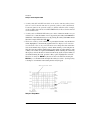
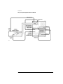
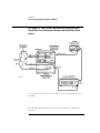
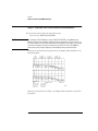
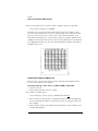
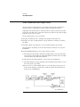
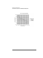
The jitter tolerance measurement process is as follows:
a Perform a BER measurement of the DUT with jitter-free data.
b Attenuate the signal power until the onset of errors or a specific BER is
achieved.
c Reduce the attenuation 1 dB.
d The results of the BER test are monitored by the 71501D, where the 71501D
compares the actual BER performance to the desired level (defined by you)
to determine the pass or fail status.
e This process is repeated for each test point as defined by the test template.
Margin Testing
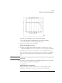
The above method is used to verify compliance to a given test standard. If the
DUT passes the test, it is still unknown just what level of tolerance is achievable. You can perform a margin test by selecting a percentage margin by which
to increase the jitter magnitude at each test point.
Tolerance
Searching
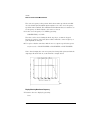
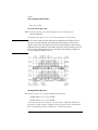
You could also use another technique where you perform a tolerance search.
In this mode the 71501D initially performs the BER test with the jitter level set
to that of the template. The jitter will then be systematically increased by a
factor that you define and a BER test performed until the desired BER limit is
exceeded, or the test system generation capability is exceeded. If the DUT is
not capable of achieving basic compliance levels, the search factor can be set
to a negative level. In this mode, the jitter level will be decreased until a level
is reached where the DUT can maintain the desired BER.
Single-Point
Testing
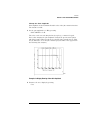
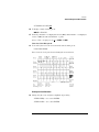
For single point testing, the jitter frequency and magnitude can be arbitrarily
selected and a BER test performed.
All of these jitter tolerance tests may also be performed on multiplexing and
de-multiplexing devices.
Jitter Tolerance
of Devices with No
Clock Output
Signal
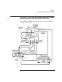
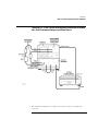
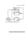
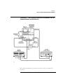
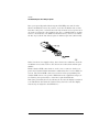
If the DUT has no recovered clock output, the source of the clock signal for
the error performance analysis would be the same as what would be used for a
conventional BER test (as if no jitter were applied to the data). For example,
the clock output of the pattern generator might be used as an input to the
error detector.
4-12