1
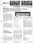
SERVICE INFORMATION FROM HEWLET-PACKARD
1st Quarter 1994
The Optical Spectrum Analyzer
Sensitivity
;'
=
Part 3
Mike LevernierlHmlett-Packard
tical spectrum analyzers, see the previous issue of Bench Briefs.) Figure 1
shows the display of a signal that has
an amplitude equal to the sensitivity
setting of the optical spectrumanalyzer.
r
Introduction
In the previous issue of Bench Briefs
Richard Ogg explained the optical
spectrum analyzer in terms of signal
processing, various operating modes,
noise generation, and the control of
noise through filtering schemes. In
this issue, Mike Levemier describes
OSA sensitivity through HewlettPackard's patented way of allowing
the user to directly enter the required
sensitivity level - what HP calls a
"sensitivity function." For more detailed information on optical spectrum analysis basics, order Application Note 1550-4, Optical Spectrum
Analysis, HP Pub. No. 5091-3054E
from your local HP sales/serviceoffice.
Single monochromators typically
have sensitivity about 10 to 15 dB better than that of double monochromators due to the additional loss of the
second diffraction grating in double
monochromators. The double-pass
monochromator has the same high
sensitivity of single monochromators
even though the light strikes the diffraction grating twice. The high sensitivity is made possible by the halfwave plate and the use of a smaller
photodetector that has a lower noise
equivalent power (NEP).
I
1
c-
Sensitivity is defined as the minimum
detectable signal or, more specifically,
six times the rms noise level of the
instrument. Sensitivity is not
specified as the average noise level,
as it is for RF and microwave spectrum analyzers, because the average
noise level of optical spectrum analyzers is 0 watts (or minues infinity
dBm). (For more information on the
differences between electrical and opPub. No. 5952-3465
Tuning Speed
Sensitivity can be set directly on
Hewlett-Packard optical spectrum
analyzers, which then automatically
adjust to optimize the sweep time,
while maintaining the desired sen-
Sensitivity - Directly Settable
by the User
'1
sitivity. Sensitivity is coupled directly
to video bandwidth, as shown in
Figure 2. As the sensitivity level is
lowered, the video bandwidth is decreased (or the transimpedance
amplifier gain is increased), which results in a longer sweep time, since the
sweep time is inversely proportional
to the video bandwidth. The sweep
time can be optimized because the
video bandwidth is continuously variable and just enough video filtering
can be performed. This avoids the
problem of small increases in sensitivity causing large increases in sweep
time, which can occur when only a
few video bandwidths are available
in fairly large steps.
Sweep-Time Limits
For fast sweeps, sweep time is limited
by the maximum tuning rate of the
monochromator. The direct-drive-
%!-38
08
dBn
Sensitivity = -80 dBm-
RB E 1 nn
UE 208 H z
S
SI-950
i ~ e c
Figure 1. Display of signal with amplitude equal to sensitivity level.
WWW.HPARCHIVE.COM
0 1994 Hewlett-Packard
SENS - 8 2 dBm
5.00 d8lOlU
Video BW
300 Hz-
S T R R T 1 1 5 0 . 0 nm
* R E 1 nm
x U B 3 8 HZ
S
S T O P 1 1 5 0 . 0 nn
* S T 18 s e c
Figure 2. Video bandwidth directly affects sensitivity.
motor system allows faster sweep
rates when compared with optical
spectrum analyzers that use gear-reduction systems to rotate the diffraction grating.
For high-sensitivity sweeps that tend
to be slower, the small photodetector
and continuously variable digital
video bandwidths allow faster sweep
times. The small photodetector reduces the sweep time because it has
a lower NEP than the large photodetectors used in other optical spectrum analyzers. Lower NEP means
that for a given sensitivity level, a
wider video bandwidth can be used,
which results in a faster sweep.
(Sweep time is inversely proportional
to the video bandwidth for a given
span and resolution bandwidth.)
The continuously variable digital
video bandwidths improve the sweep
time for high-sensitivity sweeps in
two ways. First, the implementation
of digital video filtering is faster than
the response time required by narrow
analog filters during autoranging.
Second, since the video bandwidth
can be selected with great resolution,
just enough video filtering can be
used, resulting in no unnecessary
sweep-time penalty due to using a
narrower video bandwidth than is required. Figure 3 shows a 20 second
filter-response measurement. This filter, for an erbium amplifier, was
stimulated by a white-light source
and the figure shows the normalized
2
BENCH BRIEFS
Figure 3. Improved sweep times, even for
high sensitivity measurements that traditionally result in slow sweeps. This plot
shows the normalizedoutput of an erbium
amplifier filter that was stimulated by a
white-light source.
response. The purpose of this filter is
to attenuate light at the pump wavelength, while passing the amplified
laser output of 1550 nm. Due to the
low power level of white-light
sources, this measurement requires
great sensitivity, which traditionally
has resulted in long sweep times.
changed to reposition the signal in the
measurement range of the analyzer's
internal circuitry, and the sweep continues. This repositioning explains
the pause that can occasionally be
seen in a sweep with a wide measurement range.
Autoranging Mode
Autoranging mode is activated automatically for sweeps with amplitude
ranges greater than about 50 dB. The
amplitude range is determined by the
top of the screen and the sensitivity
level set by the user. With the autoranging mode activated, when the
signal amplitude crosses a threshold
level, the sweep pauses, the transimpedance amplifier's gain is
Chopper Mode
The main purpose of the chopper
mode is to provide stable sensitivity
levels for long sweep times, which
could otherwise be affected by drift
of the electronic circuitry. The desired
stability is achieved by automatically
chopping the light to stabilize electronic drift in sweeps of 40 seconds
or greater. The effect is to sample the
noise and stray light before each trace
point and subtract them from the
"1
(See 'optical Spectrum Analyzer," page 8)
-
Non-Chopper Mode
Chopper Mode (ST
= 41 Sec)
Figure 4. Dynamic range improvement from chopper mode.
WWW.HPARCHIVE.COM
1ST QUARTER 1994
1
1994
Logistics
Data Book
tract numbers for provisioned products, and recommends replacements
for discontinued products. The companion microfiche lists NSNs for
product components and can be requested with postage-paid cards included in the data books.
John CloutierIHmlett-Packard
If your work requires U.S. Government National Stock Numbers
(NSNs) for HP products and their
components, HP’s annual Logistic
Data Book and its companion microfiche are must-have resources.
The data book cross references HP
product numbers to National Stock
Numbers (NSNs) and Joint Electronic
Type Designators (JETDs), lists con-
r
Safety-Related
Service Notes
on the rear of the E1401A Mainframe.
If a hazardous AC Voltage is present
(greater than 30 VAC RMS, or 42 VAC
peak), your unit is hazardous.
Service Notes from Hewlett-Packard
relating to personal safety and possible equipment damage are of vital
importance to our customers. To
make you more aware of these important notes, they are printed on paper
with a red border, and the service
note number as an “-S” suffix. In
order to make you immediately aware
of any potential safety problems, we
are highlighting safety-related service
notes here with a brief description of
each problem. Also, in order to draw
your attention to safety-related service notes in the service note index,
each safety-related service note is
highlighted with a contrasting color.
A new power supply must be installed. Order Safety Service Note
E1401A-02-S (document ID number
5758 on the HP FIRST system) for
more information.
HP E1401A VXI C-Size High-Power
Mainframe
Serial Numbers Affected
3227A00165 I 3227A00207
E4095A/B PT500 Protocol Tester
Serial Numbers Affected
03-0000 I CA33330209
L
p
Build-up of surface contamination inside the E1401A power supply plus a
jumper wire with damaged insulation
may cause a shock hazard to exist on
an externally-accessible pin on the
rear panel of the E1401A.
Check your unit as follows: Connect
a voltmeter between chassis ground
and pin #23 on the Sub-D connector
1ST QUARTER 1994
E3910A/B PT500 Protocol Tester
Serial Numbers Affected
08-0000 I CA33350292
E3939A/B PT500 Protocol Tester
Serial Numbers Affected
CA32220000 I CA33300023
E4093A/B PT500 Protocol Tester
Serial Numbers Affected
02-0000 I CA33320025
E4100B PT500 Protocol Tester
Serial Numbers Affected
CA33130001 I CA33150006
IDAC-M-XPE PT500 Protocol Tester
Serial Numbers Affected
CA32090001 I CA33010010
IDAC-MPT PT500 Protocol Tester
Serial Numbers Affected
01-0000 101-9999
WWW.HPARCHIVE.COM
To obtain a free copy of the 1994
Logistics Data Book, contact your
nearest HP office, or:
John Cloutier
Hewlett-Packard Company
Federal Support Services
MS 51U-TH
P.O. Box 58059
Santa Clara, CA 95052-8059
0
High voltage applied to the connector
module plane or connector module
handle could cause the existing
ground path to open, resulting in a
possible shock hazard to the user.
Affected units must be retrofitted
with grounding wires to rectify the
problem. Contact your local HP sales1
service office and your unit will be
repaired free of charge.
For more information, order the following Product Safety Service Notes
using the HP FIRST FAX system.
Product Safety
Service Note
E391ONB-02-S
E3939NB-02-S
E4093NB-02-S
E4095NB-02-S
E4100B-024
IDAC-M-XPE-02-S
IDAC-MPT-024
HP FIRST
Doc. ID No.
5961
5962
5063
5064
5065
5066
5067
0
BENCH BRIEFS
3
How is the Recommended Calibration Cycle Determined?
Jim SteadlHewlett-Packard
90% did not require any adjustments).
Introduction
and AM bandwidth calibration that
fall into the user calibration category.
/I
New Circuit Designs
For T&M products, HP usually indicates in the manual a recommended
calibration cycle. For many microwave instruments this is typically a
one-year recommendation. With
calibration costs rapidly increasing,
longer calibration cycles are required
to maintain a reasonable cost of ownership. Following is an explanation of
some of the steps involved in determining how an extended cycle can be
justified.
Past Experiences
Most companies maintain a database
on past calibrations and can easily determine what percentage of instruments required adjustments. This
data is then used to appropriately
change the calibration cycle. HP
maintains such a database for instruments used in our microwave instrument production facility. As an
example, when the HP 8360 was introduced we looked at the data for a
similar product, the HP 8340A. The
data indicated that under normal
operating conditions the recommended one-year calibration cycle for
the HP 8340A was conservative (Le./
Mechanical Wear
Design improvements are also used
to justify extended calibration cycles.
Reduced parts count and fewer
hardware adjustments mean there is
less chance for drift or aging to have
an effect on the calibration. In addition, newer circuit designs may provide better stability. When compared
to the HP 8340A, the HP 8360 series
has about one-third fewer components and about 25% of the HP 8340A
hardware adjustments. Long-term
ALC stability was also improved
through the use of a Planar-DopedBarrier (PDB) diode as the leveling
detector.
User vs. Self Adjustments
Periodic adjustments are sometimes
required for optimum performance.
To maintain an extended calibration
cycle, it is important that these adjustments are either done automatically
by the instrument, or set up as user
adjustments. Both the HP 8340A/B
and HP 8360 series use auto tracking
to maintain maximum RF output
power. In addition, the HP 8360 series
has both frequency span calibration
Sometimes the instrument or system
environment has a large influence on
the long-term stability of the product.
A good example is the HI' 8510 system. Normal usage of a network
analyzer requires that devices be connected and disconnected to make
measurements. Over an extended
time period this results in the connectors being subjected to wear and/or
damage. For this reason, the HP 8510
recommended calibration cycle is limited to one year and will probably
never be extended.
\
4
1'
Conclusions
The recommended calibration cycle is
just that; a recommendation. Operating environment and the user's application are variables that cannot be
included in the manufacturer's
recommendation. The published
cycle should be used by the customer
to help determine an initial calibration
cycle. Then an ongoing data collection
process should be initiated to determine the best calibration cycle for the
customer's application.
'7
1994 Bench Briefs' Instrument
Service Note Index
HP FIRST (208)344-4809
T & M Section - Press 4
Password Section - Press 3
Password - 76683
SN
SN
Type No.
MA 3324A-03
IO
3456A-25
MR 3457A-17
IO
35653-07
IO
3577A-17
IO
3577B-07
4
BENCH BRIEFS
Abstract
'/
t
New firmware must be installed with new A6 Signal Source Board
Clarification of product specifications and calibration cycle
Modification prevents shorting of multiple channels
Reprogramming required for use with HP 35630A/B VISTA software
Source harmonic distn spec changed from -30 dBc to -25 dBc
Source harmonic distn spec changed from -30dBc to -25 dBc
WWW.HPARCHIVE.COM
?
HP FIRST
Document ID No.
5708
5706
5985
5977
5978
5979
1ST QUARTER 1994
~~
4
3
SN
SN
Abstract
Type No.
MR
IO
IO
MA
MA
MR
MR
MR
IO
MR
MR
MR
IO
MA
MR
MR
MR
IO
IO
IO
IO
MR
MR
IO
IO
IO
IO
IO
IO
MR
IO
MA
MR
MA
MR
MR
IO
MR
MA
MR
MR
MA
IO
MR
IO
MA
MR
MA
MR
IO
MA
MA
MA
MA
IO
3589A-03
3784A-03
3784A-04
3784A-05
3785A-25
4155A-01
4156A-01
4291A-01
4396A-08
4396A-09
4396A-10
4396A-11
4396A-12
4957A-01C
4980A-11
4981A-11
4982A-11
5071A-01
5071A-02
5529A-01A
5529V-01A
6060B-02
6063B-02
6651A-03
6652A-03
6653A-03
6654A-03
6655A-03
8130A-03
8560A-26C
8560A-27
8560A-28
8560E-02C
8560E-06
8560E-07
8561B-25C
8561B-27
8561E-01C
8561E-05
8561E-06
8562A-67C
8562A-68
8562A-69
8563A-20C
8563A-21
8563A-22
8563E-02C
8563E-07
8563E-08
8566B-10B
8566B-19A
8567A-03A
8568A-37B
8568B-08A
8568B-10B
1ST QUARTER 1994
HP FIRST
Document ID No.
C1405A/B keyboard incompatibility with HP 3589A
Mod optimizes the HP 3784A for burst mode operation
Instructions to retrofit Opt 002 to a standard instrument
Mod to housing for pwr supply caps C1 and C2
Mod ensures conformance to performance test
Updating the preliminary ROMs with formal-releasedROMs
Updating the preliminary ROMs with formal-released ROMs
New A3A3 assembly improves osc level (self-test 15)
New key cap for power line switch
New A3A3 assembly improves RF output level (self-test 16)
Modification prevents rubber key from sticking
Mod corrects PHASE LOCKED LOOP UNLOCKED error at high temp
Option upgrade procedures
Available option allows high speed option retrofitting
LED board mod allows greater range of brightness adjustment
LED board mod allows greater range of brightness adjustment
LED board mod allows greater range of brightness adjustment
Unusual power-up seq can cause pseudo “Fatal Error” message
HP 5071A performance test
List of software revision A.01.13 anomalies
List of software revision A.01.13 anomalies
Safety compliance of RFI filter cap discharge time constant
Safety compliance of RFI filter cap discharge time constant
Mod reduces radiated RFI when replacing A2 HPIB board
Mod rcduces radiated RFI when replacing A2 HPIB board
Mod reduces radiated RFI when replacing A2 HPIB board
Mod reduces radiated RFI when rcplacing A2 HPIB board
Mod reduces radiated RFI when replacing A2 HPIB board
List of differences in mechanical/electrical major parts
Recommended replaccment of 5-volt regulators
Incorrect manual procedure cannot measure resol B/W accuracy
Diodes w/higher breakdown voltage improves focus reliability
Recommended replacement of 5-volt regulators
Diodes whigher breakdown voltage improves focus reliability
5-volt regulator reliability improvement on A6 PC board
Recommended replacement of 5-volt regulators
Incorrect manual procedure cannot measure resol B/W accuracy
Recommended replacement of 5-volt regulators
Diodes whigher breakdown voltage improves focus reliability
5-volt regulator reliability improvement on A6 PC board
Recommended replacement of 5-volt regulators
Diodes whigher breakdown voltage improves focus reliability
YTF adjustment procedure
Recommended replacement of 5-volt regulators
Incorrect manual procedure cannot measure resol B/W accuracy
Diodes w/higher breakdown voltage improves focus reliability
Recommended replacement of 5-volt regulators
Diodes with higher breakdown voltage improves focus reliability
5-volt regulator reliability improvement on A6 PC board
Option 462 6 dB resolution bandwidths
RF attenuator with calibration ROM replacement
RF attenuator retrofit kit, HP P/N 85680-60228
RF attenuator with calibration ROM replacement
RF attenuator with calibration ROM replacement
Option 462 6 dB resolution bandwidths
WWW.HPARCHIVE.COM
5937
5692
5693
5694
5695
5994
5995
5968
5917
5969
5970
5996
5997
5014
5929
5930
5931
5719
5720
5900
5901
5761
5762
5944
5945
5946
5947
5948
5949
5739
5714
5950
5740
5951
5923
5741
5715
5742
5952
5924
5743
5953
5938
5744
5716
5954
5745
5975
5925
5955
5688
5689
5690
5691
5956
BENCH BRIEFS
5
SN
SN
Type No.
IO
IO
IO
IO
IO
IO
IO
IO
MA
IO
IO
MA
IO
IO
MA
IO
IO
MA
IO
IO
IO
MR
IO
IO
MR
IO
IO
IO
IO
IO
IO
IO
IO
IO
MR
MR
MR
MR
IO
IO
MR
MR
MR
MR
MR
IO
IO
IO
IO
MA
MR
MR
SA
MR
MR
6
8593E-01
8593E-03
8594E-01
8594E-03
8595E-01
8595E-03
8596E-01
8596E-03
8643A-01
8643A-02
8643A-03
8644A-01
8644A-02
8644A-03
8644B-01
8644B-02
8644B-03
8645A-02
8645A-03
8645A-04
8664A-02
8664A-03
8664A-04
8665A-03
8665A-04
8665A-05
8665B-02
8665B-03
8683A-03
8683B-04
8683D-04
8684A-05
8684B-07
8684D-05
8711A-02
8711A-03
875114-17
8751A-22
8751A-24
8920A-07
8920A-08
8920D-01
8920DTS-01
8921A-01
8921D-01
899OA-01
8991A-01
8991A-02
8992A-01
E1222M-09
E1300A-02
E1301A-03
E1401A-02-S
E1446A-01
E1672A-01
BENCH BRIEFS
Abstract
HP FIRST
Document ID No.
Additional equipment required during Option 012 calibration
List of specific test equipment reqd for Opt 151,163 calib
Additional equipment required during Option 012 calibration
List of specific test equipment reqd for Opt 151,163 calib
Additional equipment required during Option 012 calibration
List of specific test equipment reqd for Opt 151,163 calib
Additional equipment required during Option 012 calibration
List of specific test equipment reqd for Opt 151,163 calib
RPP Module modification reduces noise floor of RF output
Jitter is normal for internal modulation source
Cable replacement and identification
RPP Module modification reduces noise floor of RF output
Jitter is normal for internal modulation source
Cable replacement and identification
RPP Module modification reduces noise floor of RF output
Jitter is normal for internal modulation source
Cable replacement and identification
RPP Module modification reduces noise floor of RF output
Jitter is normal for internal modulation source
Cable replacement and identification
Jitter is normal for internal modulation source
Recommended replacement Reverse Power Protection assembly
Cable replacement and identification
Jitter is normal for internal modulation source
Recommended replacement Reverse Power Protection assembly
Cable replacement and identification
Jitter is normal for internal modulation source
Cable replacement and identification
Field support kit and assembly obsolescence
Field support kit and assembly obsolescence
Field support kit and assembly obsolescence
Field support kit and assembly obsolescence
Field support kit and assembly obsolescence
Field support kit and assembly obsolescence
Cable replacement corrects display instability problem
Incorrect part in service kithcorrect procedure in manual
Modification fmes unexpected spurious problem
Mod prevents hang ups or unexpected resets
New key cap for power line switch
Instructions for replacing the motherboard
Incorrect RF diagnostics results (Option 007)
Early units require FW upgrade for use with HP 11807A Opt 009
Early instuments require hardware and firmware upgrades
H/W and F/W upgrade required for 83201A compatibility
Early units require FW upgrade for use with HP 11807A Opt 009
Save A1 control board assembly top and bottom shields
Save A1 control board assembly top and bottom shields
Part number correction for the A1 control board assembly
Save A1 control board assembly top and bottom shields
Upgrade address space for error map to 1Mbyte
New time-delay fuse corrects intermittent fuse failure
New time-delay fuse corrects intermittent fuse failure
Recommended modification to prevent possible shock hazard
New fuse prevents output from sticking at +24 or -24Vdc rail
Mod reduces Trig output levels when loaded with 50 ohms
WWW.HPARCHIVE.COM
5763
5988
5764
5989
5765
5990
5766
5991
5721
5722
5767
5723
5724
5768
5725
5726
5769
5727
5728
5770
5729
5747
5771
5730
5748
5772
5731
5773
5700
5701
5702
5703
5704
5705
5717
5718
5736
5737
5918
5699
5774
5958
5959
5749
5960
5939
5940
5941
5942
5760
5756
5757
5758
5759
5936
1ST QUARTER 1994
f
Y
c
f
SN
SN
Abstract
Type No.
IO
10
IO
MR
MR
MR
MR
MR
MR
MR
MR
PS
IO
PS
IO
PS
IO
PS
IO
PS
IO
PS
PS
MR
MR
MR
MA
MA
MR
IO
IO
MR
MR
10
MR
MR
IO
MR
MR
MR
IO
IO
MR
SM
MR
MA
MA
IO
MA
IO
IO
IO
IO
IO
MA
E2500B-08
E2505A-01
E2505A-02
E2550A-01
E2550A-02
E2755A-01
E3611A-03
E3614A-01
E3615A-01
E3616A-01
E3617A-01
E3910AIB-02-S
E3910B-01
E3939AIB-02-S
E3939B-01
E4093A/B-02-S
E4093B-01
E4095A/B-02-S
E4095B-01
E4100B-02-S
E4240B-01
IDAC-M-XPE-02-S
IDAC-MPT-02-S
J2213A-03
J2219A-02
11612A/B-01
16092A-01
16099A-01
16339A-02
16500B-01
18281A-01B
18281A-02
34401A-03
34401A-04
35280A-01
35650A-01
35650B-01
35650B-02
35652AIB-01
35665A-02A
37704A-01
37741A-01
37743A-01
53310-0194-01
66oooA-02
70001A-17A
70004A-13
70301A-03
70320A-01
70320A-02
70320A-03
70322A-02
70322A-03
70700A-01C
7082OA-02
1ST QUARTER 1994
HP FIRST
Document ID No.
Changes to performance test software for pulse on/off tests
New table provides correct ref designators during test 3xx
Changes to performance test software for pulse ordoff tests
Mod corrects synchronization problems in parallel operation
New firmware improves performance
Mod improves reset and futes crosstalk on FG60 control board
Elimination of RF oscillation for lightly loaded supply
New fuse eliminates intermittent blowing (Opt OE3)
New fuse eliminates intermittent blowing (Opt OE3)
New fuse eliminates intermittent blowing (Opt OE3)
New fuse eliminates intermittent blowing (Opt OE3)
Inadequate ground may cause possible shock hazard
Fan speed regulator no longer required
Inadequate ground may cause possible shock hazard
Fan speed regulator no longer required
Inadequate ground may cause possible shock hazard
Fan speed regulator no longer required
Inadequate ground may cause possible shock hazard
Fan speed regulator no longer required
Inadequate ground may cause possible shock hazard
Fan speed regulator no longer required
Inadequate ground may cause possible shock hazard
Inadequate ground may cause possible shock hazard
LED board mod allows greater range of brightness adjustment
LED board mod allows greater range of brightness adjustment
Mod corrects open DC force path caused by incorrect wiring
New metal clips improve contact repeatability
New flat-head mounting screws improve test fuRure mounting
New miniature banana-plug cable wire eliminates breakage
170MB hard disk drive update for 16500B mainframe
Country specific firmware is available
Mod remove PS3 to prevent network crashes
Mod improves time stability of DC current ranges (1OmA/100 mA)
Explanation of indicated calibration failure of AC current
Repositioningint gnding lock washer elimis source sig probs
CR1 on ps brd fails due to excessive tightening of heat sink
Shield reduces magnetic emissions when fan assy replaced
Mod for use with 35659A Opt AMV or H 0 1
Mod improves reliability of microdot connector
Mod corrects C1405A/B Keyboard failures
Instructions to retrofit Opt 001 to a standard instrument
Installation of HP 15850A Opt H03
Mod corrects incorrectly loaded capacitor on transmitter brd
Installing Option 001 into an HP 53310A
New resistor values for ac line input prevents failure
New reset programmable array logic (PAL) integrated circuit
New PAL circuit allows MODRST line on A4 to be bi-directional
New 20 dB attenuator has longer semi-rigid cable
RPP Module modification reduces noise floor of RF output
Jitter is normal for internal modulation source
Cable replacement and identification
Jitter is normal for internal modulation source
Cable replacement and identification
Information on new firmware
Firmware revision 1.1increases trace capability
WWW.HPARCHIVE.COM
5752
5753
5754
5935
5984
5986
5998
5971
5972
5973
5974
5%1
5912
5962
5913
5963
5914
5964
5915
5965
5916
5966
5967
5932
5933
5982
5919
5920
5709
5993
5222
5934
6001
6002
5999
6000
5980
5987
5981
5922
56%
5697
5698
5976
5957
5983
5992
5707
5732
5733
5775
5734
5776
5293
5750
BENCH BRIEFS
7
SN
SN
Type No.
MR
MR
IO
IO
MR
MR
IO
IO
MR
IO
MR
MR
MR
MR
70908A-07
85032B-01
85620A-04
85620A-05
85644A-02
85645A-02
86791A-01
86793A-01
87510A-05
87510A-08
S9410A-OlC
89410A-02
89440A-01C
89440A-02
Abstract
HP FIRST
Document ID No.
Mod reduces n x 300 MHz residual responses
Corrections to spec errors in O/S manual and customer letter
Module hangup is caused by improper programming
Downloadable programs may not be compat w/earlier modules
Mod eliminates 1MHz osc on output of tracking source
Mod eliminates 1MHz osc on output of tracking source
Service manual update, part number 86791-90004
New table provides correct ref designators during test 3xx
Modification fmes unexpected spurious problem
New key cap for power line switch
New FW fuces calibration timing problem
New analog motherboard improves channel match
New FW fmes calibration timing problem
New analog motherboard improves channel match
Service Note Types
IO
Information Only
MR Modification Recommended
PS
Priority Safety
MA
SA
Shl
5751
5926
fT -
5746
5943
5927
5928
5735
5755
5738
5921
5710
5711
5712
5713
Modification Available
Safety
Interoffice Service Memo (IOSM)
rOptical Spectrum Analyzer,"continued from page 2)
trace point reading. In all modes of
operation, Hewlett-Packard optical
spectrum analyzers zero the detector
circuitry before each sweep.
Improved dynamic range is another
benefit of sampling the stray light before each trace point. For measurements requiring the greatest dynamic
range possible, some improvement
can be obtained with the use of the
chopper mode. While this mode does
improve dynamic range, it is not required for the analyzers to meet their
dynamic range specifications.
Figure 4 shows the improved
dynamic range obtained by activating
the chopper mode.
This concludes the series on optical
spectntm analyzers. Bench Briefs
wants to thank Richard Ogg, Carla
McCarter, and Mike Levemier of the
Hewlett-Packard Microwave Technology DivisioniLightwave Operation for their contributions to this
series.
0
Bulk Rate
US. Postage
San Jose, CA
Permit No.
Volume 34 Number 1
Service information from
Hewlett-Packard Company
To obtain a qualification form for a free
Subscription, send your request to the
above address.
Reader comments or technical article
contributions are welcomed.
Please send them to the
Bench Briefs Editor at the above address.
f
Editor: Jim Bechtold
Hewlett-Packard
All righls reserved Permission to reprinl Bench Briels granted upon wrillen request to the Editor
8
BENCH BRIEFS
WWW.HPARCHIVE.COM
Printed in U.S.A.
1ST QUARTER 1994