1
Chapter 5
Inspecting an Object that Spans Two Image Frames
4.
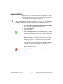
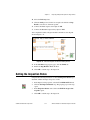
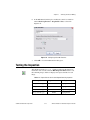
Select the following measurements from the Input Measurements
list:
•
Find Right Edge»Edge [1].X Position (Calibrated)
•
Find Left Edge»Edge [1].X Position (Calibrated)
5.
Click Next.
6.
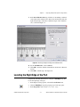
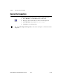
Click Add New Output Result. A new output appears in the Output
Results list.
7.
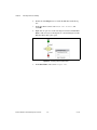
In the Name control, enter Part Width. This output will contain the
results of Equation 5-2.
8.
Make sure Type is set to Numeric.
9.
Click Add New Output Result again.
10. In the Name control, enter Right (LC). This output will contain the
results of Equation 5-1.
11. Make sure Type is set to Numeric.
12. Click Finish to close the Calculator Setup Wizard.
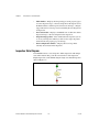
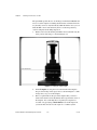
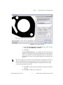
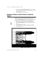
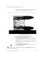
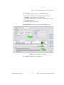
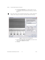
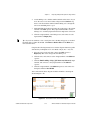
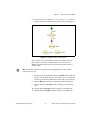
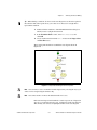
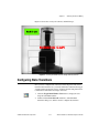
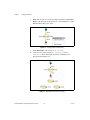
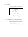
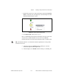
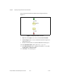
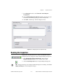
The Main window now displays a diagram with the measurement inputs
and result outputs you specified in the Calculator Setup Wizard, as shown
in Figure 5-7. The diagram also contains a default Boolean result named
Step Result. You can connect the result of a computation to Step Result,
which changes the status of the Calculator step to the result of the
computation. Refer to the Making Logical PASS/FAIL Decisions with the
Calculator Step section of this chapter for more information about Step
Result.
Figure 5-7. Calculator Diagram Elements
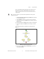
Notice that the inputs and outputs are framed with color and have codes at the
bottom of their frames. These colors and codes visually group inputs and
outputs into their respective data types—numerics, Booleans, or strings.
NI Vision Builder for Automated Inspection Tutorial
5-12
ni.com