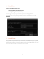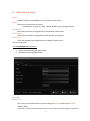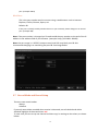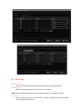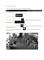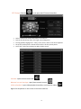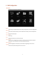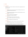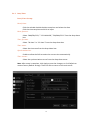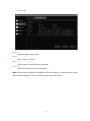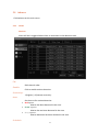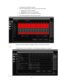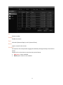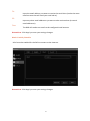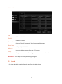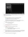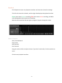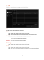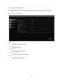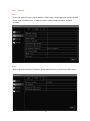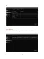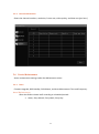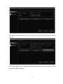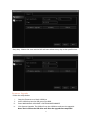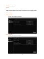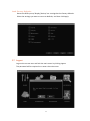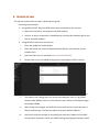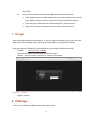
1
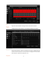
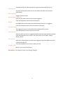
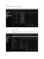
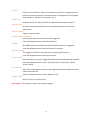
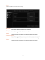
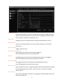
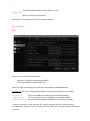
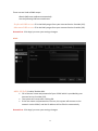
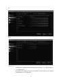
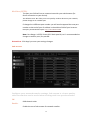
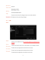
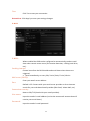
Digital Video Recorder User Manual Preface Thank you for choosing OnView. For a better understanding of the DVR, we recommend you read the instructions and safety information before use. Notice: This user manual is an operation guide only. It has no implied or stated warranty, or guaranty of the product described herein. The copy right and all rights are reserved to the company. Please do not reprint and redistribute without authorization. Please note the latest bulletin of the company for the updated version. Product Operating Environment: Please keep temperature between 32⁰F and 104⁰F. Keep away from harsh environments like high humidity. Keep out of direct sunlight and devices generating heat Do not install in harsh environments with lots of dust and smoke Keep horizontally mounted Keep installed in stable location, preventing it from falling Do not place other devices on top of it Install in well-ventilated locations. Do not block the vents. Only operate within the rated input and output voltage range Do not dismantle the product PC Requirements: To display and manage multiple audio and video channels simultaneously on your PC the following requirements must be met: CPU:Intel Core i3 550;Memory:4G;Graphics:discrete graphics with 512M, HDD: any suitable drive. This product works with Windows XP / Vista/ WIN7/ WIN8. For best viewing, resolution should be 1024×768,DirectX should be ver. 8.1 or newer 2 1 Contents 2 System Startup ............................................................................................................................. 5 3 Setup Wizard................................................................................................................................ 5 3.1 Wizard interface ................................................................................................................... 5 3.2 Administrator Login Interface................................................................................................ 6 3.3 Basic Setup ........................................................................................................................... 7 3.4 Network Setup ..................................................................................................................... 8 3.5 Network Testing ................................................................................................................... 8 3.6 DDNS and Port Setup ............................................................................................................ 9 3.7 Record Mode and Record Setup .......................................................................................... 10 3.8 HDD Setup .......................................................................................................................... 11 3.9 On-screen Taskbar ................................................................................................................ 13 4 User Login .................................................................................................................................. 15 5 DVR Configuration ......................................................................................................................... 16 5.1 BASIC.................................................................................................................................. 17 5.1.1 System setup............................................................................................................... 17 5.1.2 Date/Time .................................................................................................................. 18 5.1.3 Display ........................................................................................................................ 20 5.1.4 Record ........................................................................................................................ 21 5.2 Advance.............................................................................................................................. 25 5.2.1 Alarm .............................................................................................................................. 25 5.2.2 Network .......................................................................................................................... 35 5.2.3 COMM ............................................................................................................................ 39 5.2.4 P.T.Z................................................................................................................................ 42 5.3 Search ................................................................................................................................ 42 5.4 Disk .................................................................................................................................... 45 5.5 System Information ............................................................................................................. 46 5.5.1 Device Information ..................................................................................................... 46 5.5.2 Network ..................................................................................................................... 47 5.5.3 Online user ................................................................................................................. 48 5.5.4 Record information..................................................................................................... 49 5.6 Device Maintenance ............................................................................................................ 49 5.6.1 Basic ........................................................................................................................... 49 5.6.2 Settings ...................................................................................................................... 52 5.7 Logout ................................................................................................................................ 53 3 6 Remote Access ............................................................................................................................. 54 7 PC Login....................................................................................................................................... 55 8 PCMS Login .................................................................................................................................. 55 4 2 System Startup Power on/off: Connect the power plug to the power port on the back of the DVR. Flip the switch on the back of the DVR to On. The system will automatically run a status check and will start after a few seconds. You will see a s e t u p wizard interface after the system finishes loading. 3 Setup Wizard The Setup Wizard is a quick way to modify important settings at start-up. You can modify further settings once fully logged into the DVR. This setup wizard contains all the basic settings like time setup, network setup, HDD format reminder, etc. 3.1 Wizard interface The Wizard interface is shown below. We recommend following the guide step-by-step to initially set the most basic settings. Place a check mark '√' in the box in the lower-left corner and then click Next to proceed to modifying the basic settings. 5 3.2 Administrator Login Interface Here we recommend you set up a password for the administrator account. Then click Next for more settings; if you click Cancel, you will enter directly into the Main Menu; if you click Prev., the system goes to the previous page. Note: By default the administrator account user name is: admin. There is no password, but for better security, we strongly recommend that you set up a password here. 6 3.3 Basic Setup Date/Time, date format, time format, time zone, camera system (PAL/NTSC), and language should be set up according to the user’s needs. See below: Date/Time Setup: Click Calendar and choose the date. Click Time and a digital keyboard will appear. Date Format: Three format types: MM/DD/YYYY, DD/MM/YYYY, and YYYY/MM/DD. Time Format: 24-hour/ 12-hour. Time Zone: Click the down arrow and time zone options will be displayed. Please select your time zone. Note: Once the DVR connects to the internet, it will automatically adjust the time to the time zone you have chosen. Please make sure the time zone you choose is the desired local time zone. Camera System: Select either PAL or NTSC (North American customers: select NTSC). Language: Choose your language preference. 7 3.4 Network Setup There are two kinds of network setups: Obtain an IP address automatically (DHCP) Use the following IP address (Static IP) Select the type according to your network requirements as displayed below. For static IP, select Use the following IP address and enter the IP addresses manually. 3.5 Network Testing The system will test your network setup automatically. If a network connection cannot be established, please return to the previous page to correct the settings, and then click Next. If no testing is required, simply click Skip to go to the next page. 8 3.6 DDNS and Port Setup DDNS: Enable/ Disable. Enable DDNS to use a domain name server. Server: Choose your domain name server: onviewcloud, cctvyun or 3322, custom DDNS, no-ip, changip, dnsexit. Host Name: Enter the host name you registered on the domain name server. User Name: Enter the user name you registered on the domain name server. Password: Enter the password you registered on the domain name server. See the image below. For onviewcloud.net customers: • Set DDNS to Enable • Select onviewcloud as the server type • Leave the remaining fields blank Port Setup: Media Port: This is the port number used to connect using the OnView phone app or PCMS. Default: 9000. If this port is already used by another device on your network, please change to an unused 9 port. (example: 9001) Web Port: This is the port number used to connect using a web browser such as Internet Explorer, Firefox, Chrome, Opera, etc. Default: 80. If this port is already used by another device on your network, please change to an unused port. (example: 88) Note: if the port number is changed you’ll need to add the port number to the end of the IP address in the address field of your browser. (example: http://192.168.1.180:88) Note: the port range is: 1-65535, however some local ISPs may block port 80. We recommend changing it to something like port 88. See image below: 3.7 Record Mode and Record Setup There are two record modes: Always Schedule If you only want video recorded when motion is detected, set to Schedule and within Schedule highlight all dates and times red. To save time you can set up one channel and then copy its settings to the others, as shown below: 10 3.8 HDD Setup HDD Information: You can check the HDD capacity and HDD quantity in the HDD Setup. HDD Format: Check-mark the box under format, then click Format. Note: newly installed HDDs must be formatted through our DVR before usage. Overwrite: There are three options to choose from: by day, by capacity and never. Please select the desired method. 11 After the disk setup is completed, the save and confirm prompt will be displayed. Click Save to log out. After completing the setup wizard, the DVR will be ready to for use. If further settings modification is desired, you can log in to the menu to set them up. See below: 12 3.9 On-screen Taskbar Task Bar: right-click anywhere on the screen to open the task bar. Choose an option below: Enter the Main Menu: Single-channel full screen: click the icon. Select the channel to zoom into from the following popup screen . Four-channel full screen: click the the following popup screen. icon. Select the four channels to zoom into from Image Zoom: click the magnifying glass icon zoom. (see below) 13 and select the area on the screen to PTZ Setup: Click the icon to open the PTZ control interface. Select a channel to control: All refers to all channels PTZ can be moved up, down, left, right, and at diagonals Turning speed (ranging from "1-39"), zoom, focus, and iris can all be adjusted. Set up the preset points: choose the channel to set the preset points. Cruise line: click Cruise settings to add or delete cruise. Volume: open volume control bar. Manual record settings: open/close manual record. Video playback: open video playback interface, and view the videos. Right-click anywhere on the screen to close the task bar. 14 4 User Login Click Start to enter the login interface. Type the Device ID (default Device ID is “0”). Type the User Name and Password. The default user name is admin with no password. Note: If you changed the password during the Setup Wizard then use that password. 15 5 DVR Configuration Main Menu Click an icon to enter that submenu. Basic: System Setup, Time/Date Setup, Record Setup, Display Setup, and User Configuration Advance: Alarm Setup, Network Settings, Internet Application Settings, and PTZ Configuration. Search: Search Recorded Videos. Log Search: Search Log. Disk: Display the HDD state, and format the HDD. Information: Display current configuration parameters including: System Information, Network Information, User Information, and Video Settings Information. Maintenance: Firmware Upgrades; the frequency and schedule of upgrading can be set here. Logout: Locks the front panel and logs the current user out. 16 5.1 BASIC 5.1.1 System setup Modify device name, device ID, video format, VGA resolution, language, log-out time and startup wizard. Device name: Change the device name. Click the input box and a keyboard will pop up. Use the keyboard to edit the device name. Device ID: Change the device ID. Click the input box and a keyboard will pop up. Use the keyboard to edit the device ID. Video format: Select PAL or NTSC from the drop-down box. (North American customers select NTSC). VGA resolution: Adjust according to the VGA settings of your monitor. Select 1024×768 or 1280×1024 from the drop-down box. Language: Select the language from the drop-down menu. Logout time: Select 30 seconds, 1 minute, 3 minutes, 5 minutes, 10 minutes or Never. Startup wizard: Turn the Startup Wizard “Off” or “On” from the drop-down menu. Note: After setup is complete, click Apply to save the changes; or click Default to recover factory default settings. Then click Exit to return to the main menu. 17 5.1.2 Date/Time Date/Time Setup: Date/time: Click the calendar beside the date setup box and select the date. Click the time setup box and click to input. Date format: Select “MM/DD/YYYY,” “YYYY-MM-DD,” “DD/MM/YYYY” from the drop-down box. Time format: Select “24-Hour” or “12-Hour” from the drop-down box. Time zone: Select the time zone from the drop-down box. Synchronization: Enable to allow the DVR to attain the current time automatically. Time server: Select the synchronization server from the drop-down menu. Note: After setup is complete, click Apply to save the changes; or click Default to recover factory default settings. Then click Exit to return to the main menu. 18 DST Setup Enable: Enable Daylight Savings Time. Mode: Select “Week” or “Date.” Offset: Time period to jump forward or backward. Start time: Check your local rules for time and date. Note: After setup is complete, click Apply to save the changes; or click Default to recover factory default settings. Then click Exit to return to the main menu. 19 5.1.3 Display CH: Channel listing. Name: Click to modify the CH name. Mask: Click Settings. Left-click and highlight the areas to be masked (blacked out). Maximum of 4 separate areas can be masked. Double-click to cancel the mask. Click Apply to save. Click Default to cancel. Color: Click Settings and select one CH. Adjust Brightness, Contrast, Hue, and Saturation. Click Apply to save. 20 Overlay: Click Settings and select one CH. Select Time overlay and Name overlay. Click Default to cancel. Copy CH: Copy one CH’s settings to another CH. 5.1.4 Record Basic setting CH: DVR channel order. Enable: Click to enable video recording. Audio: Click to enable audio recording. Mode: Choose either Always or Schedule as recording mode. Always enables persistent video / audio recording (24/7). Schedule forces the system to only record based on the set schedule. Example: only record when motion is detected, etc. Copy CH: Copy one CH’s settings to another CH. 21 Bit rate CH: DVR channel order. Resolution: CIF, HD1, D1 available. Frame rate: 1-25 fps available. Quality: Best, Better, Good, Normal available. Copy CH: Copy one CH’s settings to another CH. 22 Schedule CH: DVR channel order. Configuring the schedule: Set the recording mode to Manual, Normal, or Alarm Highlight the days and times by left-clicking and dragging across the calendar Or Double-click the recording schedule; the Schedule window will pop up. You can set the recording schedule here. 23 Copy CH: Copy one CH’s settings to another CH. User Add User: Create a new user and configure its permissions. Basic information: User name, Password, Retype password, User type, Binding Client MAC, MAC. 24 5.2 Advance Click Advance on the main menu 5.2.1 Alarm Motion: Alarm will be in triggered when there is movement in the detection area. CH: DVR channel order. Enable: Click to enable motion detection. Sensitivity: 1 (highest) - 8 (lowest) sensitivity. Area: Set the area for motion detection. Red square: Motion has been detected in the area. Green square: Motion has not been detected in the area. Grey square: Motion detection has been disabled in the area. Schedule: 25 i. Click Alarm to enable the alarm. ii. Left-click and drag your mouse to set the alarm plan. Red square: Alarm enabled. Black square: Alarm is not enabled. iii. Click Apply to save. Click Default to cancel. iv. Click Exit to go back to the previous menu. Copy: Copy the current channel’s settings to one or more other channels. Trigger: Configure how the alarm behaves. Click Settings to display your options. Record: 26 Choose which channel’s video to record when the alarm is triggered on this channel. (Common practice is to have channel 1 configured to record video from channel 1, channel 2 to channel 2, etc.) Snapshot: Snapshot of the live video feed will be captured and stored on your PC. Send E-mail: An email notification will be sent to your inbox with alarm and channel information. Alarm output: Triggers external alarm. Alarm output duration: How long the external alarm will remain triggered. From the dropdown menu select the duration. Buzzer: An audible alarm will sound from the DVR when the alarm is triggered. From the dropdown menu select the buzzer’s duration. Pop-out image: The triggered channel’s video feed will be displayed full-screen. From the dropdown menu select the channel. Post-record: How long after the alarm is triggered should video be captured and recorded. From the dropdown menu select: 10s/ 30s/ 1min/ 3 min/ 5min/ 10min/ 15min/ 30min. Pre-record: How much video before the alarm was triggered should the DVR record and save to the video file. From the dropdown menu select: None/ 5s/ 10s Trigger PTZ: None/ Cruise line/ Preset point Attention: Click Apply to save your settings changes. Sensor Sensor alarm: high/low voltage abnormal alarm. 27 ID: Sensor number. Enable: Enable the sensor. Type: Select N.O (Normal Open) or N.C (Normal Close). Name: Input a name for the sensor. Schedule: Set up alarm for time periods ranging from Monday through Sunday; from 0:00 to 24:00. Double-click on the time to enter the time period setup. Red square: Alarm enabled. Black square: Alarm is not enabled. 28 Copy: Copy the current channel’s settings to one or more other channels. Trigger: Configure how the alarm behaves. Click Settings to display your options. Record: Choose which channel’s video to record when the alarm is triggered on this channel. (Common practice is to have channel 1 configured to record video from channel 1, channel 2 to channel 2, etc.) Snapshot: 29 Snapshot of the live video feed will be captured and stored on your PC. Send E-mail: An email notification will be sent to your inbox with alarm and channel information. Alarm output: Triggers external alarm. Alarm output duration: How long the external alarm will remain triggered. From the dropdown menu select the duration. Buzzer: An audible alarm will sound from the DVR when the alarm is triggered. From the dropdown menu select the buzzer’s duration. Pop-out image: The triggered channel’s video feed will be displayed full-screen. From the dropdown menu select the channel. Post-record: How long after the alarm is triggered should video be captured and recorded. From the dropdown menu select: 10s/ 30s/ 1min/ 3 min/ 5min/ 10min/ 15min/ 30min. Pre-record: How much video before the alarm was triggered should the DVR record and save to the video file. From the dropdown menu select: None/ 5s/ 10s Trigger PTZ: None/ Cruise line/ Preset point Attention: Click Apply to save your settings changes. 30 Video Loss Trigger the alarm when there is video loss. CH: DVR channel order. Trigger: Configure how the alarm behaves. Click Settings to display your options. 31 Record: Choose which channel’s video to record when the alarm is triggered on this channel. (Common practice is to have channel 1 configured to record video from channel 1, channel 2 to channel 2, etc.) Snapshot: Snapshot of the live video feed will be captured and stored on your PC. Send E-mail: An email notification will be sent to your inbox with alarm and channel information. Alarm output: Triggers external alarm. Alarm output duration: How long the external alarm will remain triggered. From the dropdown menu select the duration. Buzzer: An audible alarm will sound from the DVR when the alarm is triggered. From the dropdown menu select the buzzer’s duration. Pop-out image: The triggered channel’s video feed will be displayed full-screen. From the dropdown menu select the channel. Post-record: How long after the alarm is triggered should video be captured and recorded. From the dropdown menu select: 10s/ 30s/ 1min/ 3 min/ 5min/ 10min/ 15min/ 30min. Pre-record: How much video before the alarm was triggered should the DVR record and save to the video file. From the dropdown menu select: None/ 5s/ 10s Trigger PTZ: None/ Cruise line/ Preset point Attention: Click Apply to save your settings changes. 32 Others HDD error/HDD full/ IP conflict alarm settings. HDD error: Alarm will be triggered if hard drive error is detected. HDD full: Alarm will be triggered if hard drive becomes full. Trigger: Configure how the alarms behave. Click Settings to display your options. IP address conflict: Alarm will be triggered if there are two or more devices on the same network with the same IP address (which would prevent one or both from working). Trigger: Configure how the alarm behaves. Click Settings to display your options. 33 Record: Choose which channel’s video to record when the alarm is triggered on this channel. (Common practice is to have channel 1 configured to record video from channel 1, channel 2 to channel 2, etc.) Snapshot: Snapshot of the live video feed will be captured and stored on your PC. Send E-mail: An email notification will be sent to your inbox with alarm and channel information. Alarm output: Triggers external alarm. Alarm output duration: How long the external alarm will remain triggered. From the dropdown menu select the duration. Buzzer: An audible alarm will sound from the DVR when the alarm is triggered. From the dropdown menu select the buzzer’s duration. Pop-out image: The triggered channel’s video feed will be displayed full-screen. From the dropdown menu select the channel. Post-record: How long after the alarm is triggered should video be captured and recorded. From the dropdown menu select: 10s/ 30s/ 1min/ 3 min/ 5min/ 10min/ 15min/ 30min. Pre-record: How much video before the alarm was triggered should the DVR record and save to the video file. 34 From the dropdown menu select: None/ 5s/ 10s Trigger PTZ: None/ Cruise line/ Preset point Attention: Click Apply to save your settings changes. 5.2.2 Network LAN There are two kinds of network setups: Obtain an IP address automatically (DHCP) Use the following IP address (Static IP). Select the type according to your network requirements as displayed below. For static IP, select Use the following IP address and enter the IP addresses manually. IP address : Fill in the IP address according to your network settings. Subnet mask: Fill in the subnet mask according to your network settings. Default gateway: Fill in the default gateway according to your network settings. If there is no router in your network, fill in the IP you get from your Internet Service Provider (ISP). If there is a router in your network, make sure you have set the subnet mask correctly. 35 There are two kinds of DNS setups: Obtain DNS server address automatically. Use the following DNS sever addresses. Preferred DNS server: fill in the DNS you get from your Internet Service Provider (ISP). Alternate DNS server: fill in the DNS you get from your Internet Service Provider (ISP). Attention: Click Apply to save your settings changes. ADSL ADSL (PPPoE) : Enable/ Disable ADSL Fill in the user name and password of your PPPoE which is provided by your Internet Service Provider (ISP). The system will restart after clicking OK. If the user name and password are correct, the system will connect to the network via the PPPoE, and the IP address will be filled in automatically. Attention: Click Apply to save your settings changes. 36 3G Port Media Port: The port your DVR will use to communicate with the OnView phone app or PCMS application. The default is port 9000. If this port is occupied by another device on your network, please change to an available port. 37 Web Port (HTTP): The port your DVR will use to communicate with your web browser (for direct connection to your device). The default is Port: 80. If this port is occupied by another device on your network, please change to an available port. If changed to a different port number you will need to append the new port number to the end of your IP address in the address field of your browser. Example: port 88 would require http://192.168.0.123:88 Note: Port Range: 1-65535. Some ISP’s block port 80, so it’s recommended to change to another port, like port 88. Attention: Click Apply to save your settings changes. Sub-stream Configure your network transfer settings. Sub-stream is a lower-quality video stream that can be useful when dealing with low-speed networks. CH: DVR channel order. Enable: Enable the use of sub-stream for network transfer. 38 Resolution: QCIF/CIF Frame rate: PAL system: 1 to 25 NTSC system: 1 to 30 Quality: Normal/Good/Better/Best Copy: Copy the current channel’s settings to one or more other channels. Attention: Click Apply to save your settings changes. 5.2.3 COMM DDNS DDNS: Enable to use the DDNS service (this must be enabled to use OnView cloud services). Server: Choose your domain name server: 3322, dyndns, no-ip, changip or dnsexit. Host name: The host name you registered on the domain name server. User name: The user name you registered on the domain name server. Password: The password you registered on the domain name server. 39 Test: Click Test to test your connection. Attention: Click Apply to save your settings changes. E-MAIL E-MAIL: When enabled the DVR can be configured to automatically send an email alert when certain events occur (like motion detection, a failing hard drive, etc.). Sending interval: Choose how often the DVR should send email alerts when alarms are triggered Send immediately, or every 30s/ 1 min/ 3min/ 5 min/ 10 min. Mail server (SMTP): Enter your email server address. Port: Default is 25. Contact with your email server provider or do an Internet search for your web-based email provider (like Gmail, Yahoo Mail, etc). Connection security: None or SSL/TLS (check with your email provider). User name: Input the sender’s email address (can be the same email account that will receive your email alerts). Password: Input the sender’s email password. 40 To: Input the email address you want to receive the email alert (can be the same email account that will send your email alerts). CC: Input any other email addresses you want to also receive alerts (at most 4 email addresses). Test: The DVR will send a test email to the configured email account. Attention: Click Apply to save your settings changes. UPnP: Enable/Disable UPnP must be enabled for the DVR to connect to the Internet. Attention: Click Apply to save your settings changes. 41 5.2.4 P.T.Z CH: DVR channel order. Enable: Enable PTZ control. Protocol: Pelco-D/ Pelco-P/ Panasonic/ Sony/ Samsung/ Philips, etc. Baud rate: 1200/ 2400/ 4800/ 9600 Address: Input the address you get from the PTZ camera. Copy: Copy the current channel’s settings to one or more other channels. Attention: Click Apply to save your settings changes. 5.3 Search For video playback enter the Search menu from the Main Menu. 42 After entering the Search menu, the DVR will automatically search the current day’s (today) recorded files and display them in the right-hand window. If there are no recordings, the right-hand window will be empty. Calendar: Green and Red highlights indicate there are recordings for that date. Gray highlights indicate there are no recordings for that date. Blue highlight indicates the date you have selected. Note: When you open the playback interface, the calendar displays the current month, and the blue-highlighted date is the current date (today). Record Type: Which type of records to search for. All/ Alarm/ Normal CH: Choose the channel(s) you want to search records for. First, Prev., Next, Last: Progress through the list of recordings page by page. Lock/ Unlock: Recordings can be write-protected. Locked recordings cannot be deleted or overwritten. To unlock a locked recording, click Unlock. Backup: Select the file(s) to back-up to an external drive (USB, eSata, etc.), then click Backup. Note: If the selected files are too large for your external drive, the DVR will prompt you to change to a bigger external drive or reduce the size of the selected files. Search: Click Search to display the list of recorded files. 43 Playback: Click Playback to enter into playback interface and view the selected recordings. The left side shows the calendar, and the right side displays the playback timeline. Green color means normal recording, Red color means alarm recording, and black color (background color) means no recording. Move the horizontal bar left and right to progress/ regress through the video. Control buttons: Slow/ Fast Backward Play/ Pause Step Forward Fast Forward Drag the volume slider to adjust volume, if you don’t need audio, click the speaker to mute. Click X to exit playback interface. 44 5.4 Disk Click Disk in the main menu to manage your local hard drives. HDD The HDD capacity and HDD quantity information. HDD Format: Place a check mark √ under format, and then click Format. Note: Newly-installed HDDs must be formatted through our DVR before usage. Overwrite: Choose the manner in which older files should be overwritten. by Days/ by Capacity/ Never Overwrite Attention: Click Apply to save your settings changes. USB Storage Place a check mark √ under format, and then click Format. eSATA Place a check mark √ under format, and then click Format. Note: Click Save to retain settings changes. Click Default to revert to system defaults. 45 5.5 System Information Click Information to review information about the current configuration of the DVR. 5.5.1 Device Information Device Name: The name given to the DVR. Device ID: The ID of the DVR. Serial NO: Serial number of the DVR. Firmware Version: The firmware version of the DVR. MAC: MAC address of the DVR. 46 5.5.2 Network LAN Shows the network status, LAN IP address, subnet mask, default gateway, preferred DNS server, alternate DNS server, IP address conflict status, WAN IP address, and port numbers. ADSL Shows the network status, IP address, preferred DNS server, and alternate DNS server. 47 3G 5.5.3 Online user Shows the user name, IP address, log-in time and connection statues of online users. 48 5.5.4 Record information Shows the channel numbers, resolution, frame rate, video quality, and data rate (per hour). 5.6 Device Maintenance Access maintenance settings under the Maintenance menu. 5.6.1 Basic Firmware upgrade, DVR Standby, DVR Reboot, and Auto Maintenance Time and Frequency. Auto Maintenance: Allow the DVR to reboot itself according to scheduled periods. Never, Every Month, Every Week, Every Day 49 Every Month: the date will be shown in the drop-box. Set the date and time to auto-reboot the DVR. Every week: the date will be shown in the drop-down box. Set the day, and then choose the time to auto-reboot the DVR. 50 Every day: Choose the time and the DVR will auto-reboot every day at that specific time. Firmware Upgrade Follow the steps below: i. ii. iii. iv. Copy the firmware to a blank USB drive. Insert USB drive into the USB port of the DVR. Enter MAIN MENU->ADVANCE->SYSTEM MAINTAINANCE Click System Upgrade. The DVR will scan the USB drive and start the upgrade. Note: Don’t remove the USB drive until after the upgrade has completed. 51 Standby: Click to stand-by. Reboot: Click to reboot. Note: Click Save to retain settings changes. Click Default to revert to system defaults. 5.6.2 Settings Export settings: Copy the DVR settings to a USB drive. Import settings: Copy the DVR settings to this device. 52 Load Factory Defaults: Revert the DVR system/ display/ device/ etc. settings back to factory defaults. Select the settings you want to revert to defaults, and then click Apply. 5.7 Logout Log out the current user and lock the main menu by clicking Logout. The password will be required to re-enter the main menu. 53 6 Remote Access This section explains how to create a DVR internet group. Internet group example: 1. Using ADSL (PPPoE). Only one DVR needs to be connected to the internet. Make sure the DVR is connected to the ADSL modem. Confirm an active connection is established by checking the indicator light of the DVR or the ADSL modem. 2. Using PPPoE to connect to the internet. i. Enter the media port and web port. ii. Enter the PPPoE user name and password provided by your Internet service provider (ISP). iii. Input the DNS server IP (example: http://202.96.128.166). iv. Please refer to your local DNS settings (enter ipconfig/all in DOS to check). 6) v. The public IP will change after you restart the computer since it is by PPPoE. Please enable DDNS to link to a static domain name. Refer to the DDNS chapter to configure DDNS. vi. After saving your changes, the DVR will restart and connect to the internet via PPPoE automatically. The DVR will obtain a dynamic WAN IP address. vii. Check your internet connection by pinging the external IP address of the DVR from another computer. Check your DDNS settings by pinging the domain name 54 of the DVR. viii. Start Internet Explorer and enter the DDNS domain name of the DVR. If the DVR web port is not 80, append the correct port number to the end of the IP address. (please refer to the Internet Explorer Operation chapter) Enter the login credentials after downloading the IE ActiveX control. Input the user name and password to enter the preview interface. 7 PC Login Access the DVR through Internet Explorer. If your PC supports ActiveX you can view real-time video, download recorded video, play back recorded videos, and adjust DVR settings. Enter the external IP address of the DVR (and the port number if different than 80). Example. http://192.168.1.208:88 Enter the user name and password of the DVR to log in. Defaults-- user name: admin; password: no password (leave blank) Language options: English/ Chinese. 8 PCMS Login Refer to your PCMS User Manual for further instructions. 55 Thanks for choosing OnView. Due to firmware upgrades, the DVR functions may not match the user guide. Please feel free to contact us. Or you can log onto our website to download the newest version of the User Manual. Sorry for any inconvenience. 56