1
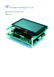
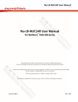
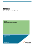
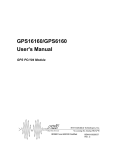
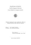
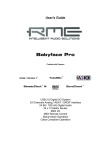
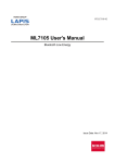
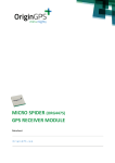
REV 2.7
Technical Description
Fastrax IT03 OEM GPS Receiver
This document describes the electrical and main functionality of the
Fastrax IT03 hardware.
April 23, 2010
Fastrax Ltd.
2010-04-23
Page 2 of 38
IT03 Technical Description_27.doc
TRADEMARKS
Fastrax is a registered trademark of Fastrax Ltd.
All other trademarks are trademarks or registered trademarks of their respective holders.
COPYRIGHT
©2003… 2010, Fastrax Ltd.
DISCLAIMER
This document is compiled and kept up-to-date as conscientiously as possible. Fastrax Ltd.
cannot, however, guarantee that the data are free of errors, accurate or complete and, therefore,
assumes no liability for loss or damage of any kind incurred directly or indirectly through the use
of this document. The information in this document is subject to change without notice and
describes only generally the product defined in the introduction of this documentation.
2010-04-23
Page 3 of 38
IT03 Technical Description_27.doc
CHANGE LOG
Rev.
Notes
Date
1.1
Preliminary documentation
2003-08-05
1.2
SPI2SDO I/O direction in 3.2
2003-08-28
1.3
Major update
2003-11-17
1.4
Updated I/O pin usage
2004-01-21
1.5
Updated I/O pin usage and application circuit
2004-02-02
1.6
Check by SW team
2004-05-27
1.7
Added moisture sensitivity information
2004-06-16
1.8
Contact 17 in page 13, modified chapter 6.1
2004-09-30
1.9
Wake-up, pin states, chapt. 4.6, ref. design
2004-12-02
2.0
Tables 3 & 4, chapt. 4.6.5, figures 6 & 7
2005-02-23
2.1
Added iTrax03 Application Board documentation
2005-09-01
2.2
Added pin description to chapter 6.
2005-09-06
2.3
Fixed some typing errors
2005-11-28
(2.4)
Added recommendations for wiring unused GPIO pins
(abandoned)
2006-06-30
2.5
PCB upgrade, module name change to IT03, corrected
internal pull up/own resistor values, corrected Wakeup
control input interrupt signal type to pulse
2009-05-27
2.6
Added disclaimer and marking codes
2010-03-16
2.7
Added notes and spec on ESD, ultrasonic sensitivity
and RoHS; updated disclaimer
2010-04-23
2010-04-23
Page 4 of 38
IT03 Technical Description_27.doc
CONTENTS
_______________________________________________________________________
1
2
3
4
GENERAL DESCRIPTION............................................................................... 7
1.1
Block Diagram ...................................................................................... 7
1.2
Frequency Plan ..................................................................................... 7
SPECIFICATIONS ........................................................................................... 9
2.1
General.................................................................................................. 9
2.2
Absolute maximum ratings ................................................................ 10
OPERATION.................................................................................................. 11
3.1
Operating modes ................................................................................ 11
3.2
Navigation/Idle mode.......................................................................... 11
3.3
Navigation/Idle mode.......................................................................... 11
3.4
Programming mode ............................................................................ 12
CONNECTIVITY ............................................................................................ 13
4.1
Connection assignments ................................................................... 13
4.2
Power supply (pins 18, 27)................................................................. 14
4.3
Reset (pin 12)...................................................................................... 15
4.4
Watchdog ............................................................................................ 15
4.5
Shared functionality ........................................................................... 15
4.6
Dedicated GPIO .................................................................................. 16
4.7
4.6.1
Boot Select (pin 16) ................................................................. 16
4.6.2
UI Indicators (pins 8, 9, 15) ...................................................... 17
4.6.3
On/Off control input (pin 14) ..................................................... 17
4.6.4
Wakeup control input ............................................................... 18
4.6.5
Sleep mode and I/O ................................................................. 18
Antenna input (pin 21)........................................................................ 20
4.7.1
Active GPS antenna ................................................................. 20
4.8
PPS output (pin 33) ............................................................................ 20
4.9
Serial ports ......................................................................................... 21
4.10 SPI-bus................................................................................................ 21
4.11 Capture timers (pins 34, 37)............................................................... 21
4.12 Pulse measurement inputs (pins 30, 31) ........................................... 21
4.13 MMC bus (pins 6, 8, 9) ........................................................................ 21
4.14 Mechanical dimensions and contact numbering .............................. 21
4.15 Suggested pad layout ........................................................................ 23
2010-04-23
Page 5 of 38
IT03 Technical Description_27.doc
5
6
7
REFERENCE DESIGN................................................................................... 24
5.1
Minimum Application Circuit Diagram .............................................. 24
5.2
Enhanced Application Circuit Diagram ............................................. 25
5.3
PCB layout issues .............................................................................. 26
IT03 APPLICATION BOARD ......................................................................... 28
6.1
General................................................................................................ 28
6.2
I/O Card Terminal connector.............................................................. 28
6.3
Bill of Materials................................................................................... 30
6.4
Application Board Circuit Drawing.................................................... 31
6.5
Application Board, Components layout ............................................ 32
6.6
Application Board, Artwork layer 1 ................................................... 32
6.7
Application Board, Artwork layer 2 ................................................... 33
6.8
Application Board, Artwork layer 3 ................................................... 33
6.9
Application Board, Artwork layer 4 ................................................... 34
HANDLING INSTRUCTIONS ......................................................................... 35
7.1
Assembly ............................................................................................ 35
7.2
Suggested Reflow soldering profile .................................................. 35
7.3
Moisture sensitivity ............................................................................ 35
7.4
Tape and reel ...................................................................................... 35
7.5
Marking ............................................................................................... 35
2010-04-23
Page 6 of 38
IT03 Technical Description_27.doc
COMPLEMENTARY READING
The following reference documents are complementary reading for this document:
Ref. #
File name
Document name
1
PRO_NMEA.html
Fastrax NMEA Protocol Specification
2
uN8130T_UM.pdf
uN8130 User’s manual
3
Reflow_soldering_
profile.pdf
Soldering Profile
2010-04-23
Page 7 of 38
IT03 Technical Description_27.doc
1
GENERAL DESCRIPTION
Fastrax IT03 is a GPS receiver module for the OEM market segment. It integrates the GPS chip
set from Atheros: the RF down-converter uN8021 and the processor uN8130. The processor
includes all base band functions needed for GPS signal acquisition, tracking and navigation.
Dedicated high-performance search engine architecture enables a rapid search of visible
satellites. A 12 channel tracking unit insures that positioning is possible even in severe conditions
such as weak signals in urban canyons. The processor provides also an internal watchdog timer.
The IT03 module interfaces to the customer’s application via a versatile I/O bus and supports
several external devices including timers, pulse measurement inputs and an MMC bus. All the
peripherals have a shared functionality with general purpose input/output (GPIO) signals.
Firmware features include e.g. build in data logger for position storage to embedded flash
memory.
The antenna input supports passive and active antennas and provides also an internal antenna
bias supply.
This document describes the electrical connectivity and main functionality of the IT03 hardware.
1.1
Block Diagram
Figure 1
1.2
Block diagram
Frequency Plan
Clock frequencies generated internally at the IT03 receiver:
2010-04-23
Page 8 of 38
IT03 Technical Description_27.doc
•
32768 Hz Real Time Clock (RTC)
•
16.3574 MHz Master Clock
•
1574.40 MHz Local Oscillator of the RF down-converter
2010-04-23
Page 9 of 38
IT03 Technical Description_27.doc
2
SPECIFICATIONS
2.1
General
Table 1
General specifications
Receiver
GPS L1 C/A-code, SPS
Channels
12
Update rate
< 5 Hz, 1 Hz (default).
Supply voltage range, VDDRF
+2.7V…+3.3 V, low ripple 2mV(RMS) max.
Supply voltage range, VDDDIG
+2.7V…+3.3 V
Power consumption
100 mW typical (without antenna bias)
Antenna net gain range
0…+32 dB
Antenna bias voltage
Same as VDDRF
Antenna bias current
Must be limited externally by VDDRF supply to
150mA max.
Operating
temperature
and
storage
-40ºC…+85ºC
Serial port configuration
Port 0: NMEA (default), iTALK optional
Port 1: iTalk
Serial data format
8 bits, no parity, 1 stop bit
Serial data speed
600, 1200, 2400, 4800, 9600, 14400, 19200,
28800, 38400, 57600, 115200, 230400, 460800,
921600 baud.
NMEA: 4800(default), iTalk: 115200(default).
I/O signal levels
CMOS compatible: low state 0.0…0.3xVDDDIG;
high state 0.7…1.0xVDDDIG
I/O sink/source
contact
capability
per
PPS modes
Accessory
I/O
functionality with GPIO)
+/- 4 mA max.
Off, Survey, Static, Roving (default)
(shared
2xCapture Timers, 2xPulse Measurement Inputs,
1xSPI-bus, MMC bus
2010-04-23
Page 10 of 38
IT03 Technical Description_27.doc
2.2
Absolute maximum ratings
Table 2
General specifications
Item
Min
Max
unit
Operating and storage temperature
-40
+85
ºC
500
mW
Power dissipation
Supply voltage, VDDDIG
-0.3
+3.6
V
Supply voltage, VDDRF
-0.3
+3.6
V
Current on any I/O pin except antenna
input
-30
+30
mA
Current output on antenna input
0
+100
mA
Input voltage on any input connection
-0.3
VDDDIG
+ 0.3
V
+160
V
+15
dBm
ESD voltage (RFIN, Machine Model)
RFIN input power
-
Note that module is Electrostatic Sensitive Device (ESD).
2010-04-23
Page 11 of 38
IT03 Technical Description_27.doc
3
OPERATION
3.1
Operating modes
After power-up IT03 boots from the internal Flash memory for normal operation. Modes of
operation:
3.2
•
Navigation/Idle mode
•
Sleep mode
•
Programming mode
Navigation/Idle mode
The IT03 receiver enters Navigation mode after it has powered up. By default it will start
navigation automatically after power-up or reset in Auto Start mode. Auto Start mode means that
all available aiding information will be used.
The module operates as long as the power supply is available. Idle mode means that the
navigation is stopped but the processor remains active. Navigation/Idle mode is also referred as
Normal Mode. The standard firmware supports versatile configuration of various operating
configurations, e.g. Logging position data etc., for further details see ref 1.
The navigation can be stopped by sending a proper NMEA or iTALK message, see also ref 1.
3.3
Navigation/Idle mode
The Sleep mode means low power operation during which no other activity other that the internal
real time clock (RTC) is present. The module enters Sleep mode via a special control message
(ref #1) or by the On/Off Control input.
The exit from the Sleep mode to the Normal mode happens in the following situations:
• an elapsed time
• an RS-232 break signal or a dummy input character to selected serial port (the low input
state should exceed 20ms)
• an interrupt from the On/Off Control input (low-to-high transition)
• an interrupt from the Wake-up input (low-high-low pulse > 20ms).
Since the internal RTC keeps the GPS time estimate, the module performs the fastest possible
navigation start depending on the availability of valid satellite/position data.
2010-04-23
Page 12 of 38
IT03 Technical Description_27.doc
3.4
Programming mode
The module enters Programming mode by two methods: HW-booting or upgrading the firmware
on-the-fly by a dedicated NMEA or iTalk command, see ref 1.
The on-the-fly upgrading requires only the serial Port 0. The downloading will start by sending a
special serial port command, after which the utility running on the host will send the new firmware
to the processor.
HW-booting is utilized by keeping the Boot Select input (pin 16, SPI2XCS3/ GPIOB22) at logic
low during power-up or system reset. Now the GPS module boots from the serial data Port 0,
sends hex 55 (U) string at 9600 baud and waits the for the boot loader commands from the host
(an application running on the host). This mode is required when there is no existing firmware
stored into the internal Flash memory.
It is recommended to support hardware based re-programming (HW-booting) in an IT03
application. This is done by adding Boot Select and XRESET control inputs into the design. See
the reference design.
2010-04-23
Page 13 of 38
IT03 Technical Description_27.doc
4
CONNECTIVITY
4.1 Connection assignments
The I/O connections are available as soldering pads with castellated via holes on the bottom side
of the module. These pads are also used to attach the module on the motherboard in the
application. All unused I/O pins should be left open (floating).
Table 3 Full system connection description of IT03. Some pins can function
as GPIO pins or in a special mode depending on the software configuration.
Pin
Signal
name
I/O
Alternative
GPIO
name
Signal description
1
GND
-
-
Ground
2
SPI1XCS0
O
GPIOB10
SPI1 chip select 0, GPIO reserved for
future use. Do not connect.
3
SPI1CLK
O
GPIOB13
SPI1 clock
4
SPI1SDO
O
GPIOB14
SPI1 data output
5
SPI1SDI
I
GPIOB15
SPI1 data input, Wake-up input (2)
6
MMCCLK
O
GPIOA12
MMC clock output
7
GND
-
-
Ground
8
MMCCMD
I/O
GPIOA13
MMC command bus, UI indicator B
9
MMCDAT
I/O
GPIOA14
MMC data bus, UI indicator A
10
GND
-
-
Ground
11
SPI2CLK
I/O
GPIOB16
SPI2 clock, output in master mode
12
XRESET
I
-
Active low async. system reset (3)
13
GND
-
-
Ground
14
SPI2SDI
I
GPIOB18
SPI2 data input, On/Off control input (1)
15
SPI2SDO
O
GPIOB17
SPI2 data output, UI indicator C
16
SPI2XCS3
I/O
GPIOB22
SPI2 chip select3, Boot Select. Pull high
with external 4.7kohm resistor.
17
SPI2XCS2
O
GPIOB21
SPI2 chip select2, (2nd boot select)
18
VDDRF
I
-
VDD for RF circuits
19
GND
-
-
Ground
20
GND
-
-
Ground
21
RFIN
I
-
RF input, antenna bias output
2010-04-23
Page 14 of 38
IT03 Technical Description_27.doc
22
GND
-
-
Ground
23
TXD1
O
GPIOA3
UART 1 async. output
24
RXD1
I
GPIOA2
UART 1 async. input
25
TXD0
O
GPIOA1
UART 0 async. output
26
GND
-
-
Ground
27
VDDDIG
I
-
VDD for digital circuits
28
RXD0
I
GPIOA0
UART 0 async. input
29
FCLK
O
GPIOA4
Pre-divided clock output of UART 1
30
PM0
I
GPIOA5
Pulse measurement input 0
31
PM1
I
GPIOA6
Pulse measurement input 1
32
GND
-
-
Ground
33
PPS
O
GPIOA7
1PPS signal output
34
TCAP0
I
GPIOA9
Timer TMG0 capture input
35
TIN0
I
GPIOA8
Timer TMG0 external clock input
36
TIN1
I
GPIOA10
Timer TMG1 external clock input
37
TCAP1
I
GPIOA11
Timer TMG1 capture input
Pin
Signal
name
I/O
Alternative
GPIO
name
Signal description
Note (1): The input has internal 18kohm pull-up resistor.
Note (2): The input has internal 9kohm pull-down resistor.
Note (3): The input has internal 100kohm pull-up resistor.
4.2
Power supply (pins 18, 27)
The IT03 module requires two separate power supplies: VDDRF for the RF parts and VDDDIG
for digital parts and I/O bus. Note that VDDDIG supply input contains internal ceramic 1uF low
ESR (0.01ohm) by-pass capacitor. Use a power supply that is specified for low ESR (<0.01ohm)
output capacitor loads. VDDDIG and VDDRF should be powered up at the same time within a
few ms.
NOTE
VDDDIG power supply should be compatible with
low ESR (<0.01ohm) ceramic capacitors.
2010-04-23
Page 15 of 38
IT03 Technical Description_27.doc
VDDRF must be linearly regulated having a low ripple 2mV(RMS) max. The typical current drain
is 24 mA in Normal (Navigation) mode. Note that VDDRF is also provided internally at the
antenna input as an active antenna bias.
NOTE
VDDRF supply current should be limited externally
below 150 mA max.
NOTE
VDDRF supply voltage should have a low ripple
2mV(RMS) max.
The VDDDIG supply may be shared with any available supply that meets the specified voltage
range. A typical current is 12 mA in Normal (Navigation) mode but it may peak up to 40 mA for
short durations. The VDDDIG supply voltage ripple should be below 40mV (RMS).
4.3
Reset (pin 12)
The system reset input (pin 12, XRESET), is an active low asynchronous reset. The processor
boots after an XRESET low-to-high transition. The XRESET input contains a 100k ohm pull-up
resistor, an open-source Power-on-Reset (POR) circuit and a Schmitt trigger in order to eliminate
the effect of noise. The POR is connected in parallel with the XRESET input and it overrides
XRESET during power-up.
For normal operation the XRESET input can be left unconnected. The module will independently
handle the reset during power-on. However, to enable the hardware re-programming, it is
advisable to connect the XRESET input for example to an open-collector or an open-source
control output.
4.4
Watchdog
The processor contains a watchdog peripheral, which resets the processor if not refreshed
frequently enough. Basically the watchdog is a 16-bit counter with enabling, disabling and
restarting controls. The watchdog counter is clocked with the frequency of 128 Hz.
4.5
Shared functionality
All the I/O pins have a shared functionality. These pins can be programmed either to have a
special function (PM, SPI, MMC etc.) or a general purpose I/O (GPIO) function.
Each signal is named according to the special functionality but also the secondary functionality is
listed as Alternative GPIO in Table 3.
With the standard firmware there are dedicated GPIO connections, which are: Boot Select, UI
Indicators and the control inputs. These shall be described in the following chapters.
2010-04-23
Page 16 of 38
IT03 Technical Description_27.doc
4.6
Dedicated GPIO
4.6.1 Boot Select (pin 16)
The boot source is defined in the internal boot ROM sector by using pins 16 (GPIOB22 /
SPI2XCS3) and 17 (GPIOB21 / SPI2XCS2). After a power-up or a system reset these pins are
internally configured to a 9kohm ohm pull-down mode for 300 clock cycles (10 µs), after which
their logic states are read. Thus, if there is nothing connected to pin 16 or 17, these pins will be
pulled low and the software will be loaded from UART Port 0. The boot source (internal Flash
memory, UART Port 0 or SPI1 bus) is processed according to Table 5.
For normal module operation pin 16 must be pulled high to VDDDIG with a 4.7k ohm pull-up
resistor. Pin 17 can be left floating.
Pin 16 is referred as Boot Select in this document. It should be connected in the application in
order to enable the hardware based re-programming.
Table 4
Boot source selection
Pin 16
Pin 17
I/O
Boot source
High
High
I
External boot sector (Flash), in case of failure
continue with SPI1 boot
High
Low
I
External boot sector (Flash), in case of failure
continue with UART Port 0 boot
Low
High
I
SPI1 boot
Low
Low
I
UART Port 0 boot
Normally, after XRESET low-to-high transition, the appropriate boot selection should be kept
active for at least 30 us. However, after connection of VDDDIG and VDDRF, the desired boot
selection should be kept active for at least 100 ms, which is due to the internal POR delay on the
XRESET signal.
NOTE
To ensure normal operation during system reset
and power on, the Boot Select (pin 16, SPI2XCS3 /
GPIOB22) requires an external pull-up resistor
connected to VDDDIG, e.g. 4.7 kohm.
Respectively, pin 17 (SPI2XCS2 / GPIOB21)
should be left open or connected to a pull-down
resistor (e.g. 4.7 kohm).
2010-04-23
Page 17 of 38
IT03 Technical Description_27.doc
4.6.2
UI Indicators (pins 8, 9, 15)
The standard firmware includes three GPIO outputs reserved as drivers for User Interface (UI)
Indicators. These outputs can be used for example to drive LEDs, which give information on the
state of the receiver.
Table 5
UI Indicators
UI
Indicator
Pin
number
I/O
Operation: High
ratio %
Signal description
A
9
O
Continuously
low state
Power Off or Sleep mode
A
9
O
Short blink 20
Normal mode, Navigation stopped
A
9
O
Long blink 80
Normal mode, Navigation started
B
8
O
Continuously
low state
Navigation stopped or not tracking
satellites
B
8
O
Short blink 20
Tracking satellites but not enough
information to calculate pseudoranges
B
8
O
Long blink 80
Pseudorange information
but not navigating
B
8
O
Continuously
high state
Navigating, Valid fix
C
15
O
Low state
No valid fix
C
15
O
High state
Valid fix available
available
The UI Indicators are updated synchronously at 1 Hz rate. The high state duty cycle is either 0%
(i.e. continuously logic low), 20% (Short blink), 80% (Long blink) or 100% (i.e. continuously logic
high).
Pin 15 (SPI2SDO / GPIOB17) indicates when a fix is available: the pin is logic high when location
fix is valid and logic low when the location fix is invalid.
4.6.3 On/Off control input (pin 14)
With the standard firmware the module can be commanded to Sleep mode by the On/Off control
input (pin 14, SPI2SDI / GPIOB18) or by a specific command. During Sleep mode only the real
time clock is running and the current consumption is reduced to about 20 uA.
Note that the worst case delay from the On/Off Control high-to-low transition to achieve Sleep
mode and reduced current drain is 300 ms. The standard firmware stores the last known good
position (LKG) and any Log data to the internal Flash memory before entering the Sleep mode.
2010-04-23
Page 18 of 38
IT03 Technical Description_27.doc
Table 6
On/Off control
On/Off
Control,
pin 14
I/O
Signal description
High
state
I
Normal (navigating) mode, delay from Sleep mode 3
ms
Low state
I
Sleep mode, delay from Normal mode 300 ms max.
NOTE
With the standard firmware the On/Off control input
(pin 14, SPI2SDI / GPIOB18) has an internal 18k
ohm pull-up resistor connected to VDDDIG and the
signal can be left unconnected for normal
operation. During Sleep mode the input is switched
internally to pull-down 9kohm resistor.
4.6.4 Wakeup control input
With the standard firmware the module can be wake up from sleep state by the Wake Up control
input (SPI1SDI / GPIOB15, pin #5) depending on the sleep mode wakeup mask. Wake Up input
is normally used only when the module has entered sleep state using the specific serial
command.
Wake up interrupt is generated by a low-high-low pulse to the Wake Up control input. The pulse
length should be at least 20 ms. The input has an internal 9kohm pull-down resistor and can be
left unconnected for normal operation.
4.6.5 Sleep mode and I/O
During the Sleep mode almost all the I/O pins are configured as inputs with internal 100k ohm
pull-down resistors. In order to reduce current leakage there are few exceptions, see Table 9.
Table 7
Pin states in Sleep mode (default firmware)
Pin
Pin mode
I/O
GPIO
mode
Signal description
1
GND
-
-
Ground
2010-04-23
Page 19 of 38
IT03 Technical Description_27.doc
2
GPIOB10
I
Pull-down
GPIO input, 9k ohm pull-down
3
GPIOB13
I
Pull-down
GPIO input, 9k ohm pull-down
4
GPIOB14
I
Pull-down
GPIO input, 9k ohm pull-down
resistor
5
GPIOB15
I
Pull-down
GPIO input, keeper
6
GPIOA12
I
Pull-down
GPIO input, 9k ohm pull-down
7
GND
-
-
Ground
8
GPIOA13
I
Pull-down
GPIO input, 9k ohm pull-down
9
GPIOA14
I
Pull-down
GPIO input, 9k ohm pull-down
10
GND
-
-
Ground
11
GPIOB16
I
Pull-down
GPIO input, 9k ohm pull-down
12
XRESET
I
-
Active low async. system reset
13
GND
-
-
Ground
14
GPIOB18
I
Pull-down
GPIO input, pull-down (Stays as
pull-up if NMEA Sleep command
was used in Normal mode.)
15
GPIOB17
I
Pull-down
GPIO input, 9k ohm pull-down
16
GPIOB22
I
Pull-down
GPIO input, 9k ohm pull-down
17
GPIOB21
I
Pull-down
GPIO input, 9k ohm pull-down
18
VDDRF
I
-
VDD for RF circuits
19
GND
-
-
Ground
20
GND
-
-
Ground
21
RFIN
I
-
RF input, antenna bias output
22
GND
-
-
Ground
23
GPIOA3
I
Pull-up
GPIO input, 18k ohm pull-up
24
GPIOA2
I
Pull-up
GPIO input, 18k ohm pull-up
25
GPIOA1
I
Pull-up
GPIO input, 18k ohm pull-up
26
GND
-
-
Ground
27
VDDDIG
I
-
VDD for digital circuits
28
GPIOA0
I
Pull-up
GPIO input, 18k ohm pull-up
29
GPIOA4
I
Pull-down
GPIO input, 9k ohm pull-down
30
GPIOA5
I
Pull-down
GPIO input, 9k ohm pull-down
31
GPIOA6
I
Pull-down
GPIO input, 9k ohm pull-down
2010-04-23
Page 20 of 38
IT03 Technical Description_27.doc
4.7
32
GND
-
-
Ground
33
GPIOA7
I
Pull-down
GPIO input, 9k ohm pull-down
34
GPIOA9
I
Pull-down
GPIO input, 9k ohm pull-down
35
GPIOA8
I
Pull-down
GPIO input, 9k ohm pull-down
36
GPIOA10
I
Pull-down
GPIO input, 9k ohm pull-down
37
GPIOA11
I
Pull-down
GPIO input, 9k ohm pull-down
Contact
Pin mode
I/O
GPIO
mode
Signal description
Antenna input (pin 21)
The module supports passive and active antennas. The antenna input impedance is 50 ohms.
The input provides also a bias supply during normal navigation operation. The antenna bias
voltage is the same as the VDDRF supply.
In the Sleep mode the antenna bias voltage is cut off internally.
The maximum tolerated antenna bias current is 100mA. It is current limited only by the external
regulator supplying VDDRF. The VDDRF supply current should be externally limited to 150 mA
max.
NOTE
Passive antennas with short-circuit to GND should
be DC blocked externally with a series capacitor
18pF… 1nF.
4.7.1 Active GPS antenna
The customer may use an external active GPS antenna for e.g. in mobile or indoor usage. It is
suggested the active antenna has a net gain including cable loss in the range from +6 dB to +32
dB.
4.8
PPS output (pin 33)
The PPS output provides a pulse-per-second signal, which can be used for timing purposes. The
default PPS mode is Roving, i.e. timing pulse is available after valid fix based on the current valid
fix position. The operating mode, pulse length and polarity are configurable via NMEA or iTALK.
Other modes are Static, Survey and Off, see ref 1 for details.
2010-04-23
Page 21 of 38
IT03 Technical Description_27.doc
4.9
Serial ports
The device supports UART communication via Port 0 (RXD0 & TXD0) and Port 1 (RXD1 &
TXD1). With the standard firmware Port 0 is configured to NMEA by default and secondary to
iTALK protocol. Port 0 is also used when the device is booting from the serial port. With the
standard firmware Port 1 is configured for iTALK communication by default and secondary to
RTCM.
The serial port logic levels are CMOS compatible. Thus, they are not directly compatible with RS232 logic levels. Use an external level converter to provide RS-232 levels, if needed. Refer to ref
1 for supported data speeds.
4.10 SPI-bus
The SPI1 in reserved internally for the RF-down-converter and externally for a custom boot
mode. Only the SPI2 device (master) is available for SDK users enabling SPI communication.
4.11 Capture timers (pins 34, 37)
Two general-purpose timers are available for SDK users with a custom firmware. TMG0 and
TMG1 have configurable prescalers and clock cycle counts. The clock input is selectable
between three sources and there is a capture mode to count external events. Each timer also
has a programmable delay, referenced to the internal epoch pulse (TME). This makes it possible
to have a specified delay between interrupts generated by the internal TME epoch, TMG0, and
TMG1. For details see ref 2.
4.12 Pulse measurement inputs (pins 30, 31)
The two pulse measurement (PM) inputs are available for SDK users with a custom firmware. PM
inputs can be used to measure with great accuracy how long an input stays high or low. For
details see ref 2.
4.13 MMC bus (pins 6, 8, 9)
The MMC bus is available for SDK users with a custom firmware. The MMC unit implements a
standard 3-wire Multi Media Card serial bus interface and provides control and data register for
easy usage of the bus. Both stream and block mode data transfers are supported. The CRC is
calculated automatically for transmitted commands and data blocks, also received responses and
data blocks are checked for correct CRC. The MMC unit has a 64-bit data buffer and is capable
of stopping bus clock to prevent buffer overflow and underflow situations. For details see ref 2.
4.14 Mechanical dimensions and contact numbering
Board size is 22.0mm (width) x 23.3mm (length) x 2.6mm (height 3.1mm max). General tolerance
is ±0.3mm. I/O contacts are using castellated via holes, which allows also hand soldering and
visual inspection of solder wetting.
2010-04-23
Page 22 of 38
IT03 Technical Description_27.doc
Figure 2
Figure 3
Dimensions
Contact numbering, top view through the package.
2010-04-23
Page 23 of 38
IT03 Technical Description_27.doc
Figure 4
Pad dimensions, bottom view.
4.15 Suggested pad layout
Figure 5
Suggested pad layout, top view through the package. Dimensions
are in mm.
2010-04-23
Page 24 of 38
IT03 Technical Description_27.doc
5
REFERENCE DESIGN
The idea of the reference design is to give a guideline for the applications using the IT03 GPS
module.
In the following two chapters the reader is exposed to design rules he should follow, when
designing an IT03 based application. By following the rules one ends up having an optimal
design with no unexpected behavior caused by the PCB itself. In fact these guidelines are quite
general in nature, and can be utilized in any PCB design related to RF techniques or high speed
logic.
5.1
Minimum Application Circuit Diagram
The Minimum Application supports communication through the UART Port 0 (NMEA or iTALK).
Other required signals are the antenna input, supply voltages for VDDRF and VDDDIG and a
pull-up resistor for the Boot Select.
Also, it is a good practice to make the IT03 application to support hardware based reprogramming of the module firmware. Due to this, one should connect Boot Select (pin 16,
SPI2XCS3 / GPIOB22) in such a way, that it can be toggled to logic low for a firmware update
through serial Port 0. In normal operation Boot Select is pulled high with a resistor (R1 in Figure
6). IT03 supports also software based “on-the-fly” programming. This does not require toggling of
the Boot Select signal. However, this method is not completely protected against unexpected
problems during the re-programming session. Because of this, the use of Boot Select in the
design is recommended.
The low drop-out linear regulator (LDO) U2 supplies +2.8 V voltage to the RF and analog parts
(VDDRF) and the digital supply (VDDDIG) is taken directly from the main supply, which in this
case is from +3.0 to +3.3 V due to the small drop-out voltage across U2. The linearly regulated
power supply is needed for VDDRF, because the maximum allowed ripple voltage for VDDRF is
2 mV(RMS). The external regulator U2 can be omitted, if such a supply is available that meets
the specified ripple voltage.
All the digital signals are routed away from the module through series resistors (R2, R3). In this
way the local oscillator (LO) signal leakage that is present in the I/O contacts of the GPS module
is suppressed. Although the LO leakage is very small at the I/O contacts of the module, it may
still interfere with the GPS reception, especially when the antenna is located very near to these
signal routes.
For the same reason capacitors C1 and C2 should be connected very close to the module with
short traces to I/O contacts and to ground plane.
Additionally, there must be another capacitor (C3: 4.7uF or bigger) from VDDDIG to the ground.
This capacitor can be located further away. If a signal from the IT03 is not needed, the
corresponding pin can be left open.
2010-04-23
Page 25 of 38
IT03 Technical Description_27.doc
Figure 6
Minimum Application Circuit Diagram.
Note that there is a DC voltage present at the RF input, when the module is operating in Normal
mode. This voltage is equal to VDDRF. If a passive antenna with short-circuit to the GND is used,
an external series DC block capacitor (18pF) must be used.
5.2
Enhanced Application Circuit Diagram
A more versatile functionality can be achieved by adding the On/Off control for the Sleep mode
and the secondary UART Port 1. Note that there is also a Wake-up input in pin 5 (SPI1SDI /
GPIOB15). One should also support hardware re-programming of IT03 by adding Boot Select
control (pin 16, SPI2XCS3 / GPIOB22). See Chapter 5.1 for more details.
2010-04-23
Page 26 of 38
IT03 Technical Description_27.doc
Figure 7
5.3
Enhanced Application Circuit Diagram.
PCB layout issues
The suggested 4-layer PCB build up is presented in the following table.
Table 8
Suggested PCB build up
Layer
Description
1
Signal + Ground with keep-out below IT03
2
Ground plane
3
Signal + Ground or VDD plane
4
Signal (short traces) + Ground
2010-04-23
Page 27 of 38
IT03 Technical Description_27.doc
Routing signals directly under the module should be avoided. This area should be dedicated to
keep-out for traces and ground (copper), except for via holes, which can be placed close to the
pad under the module. If possible, the amount of VIA holes underneath the module should be
also minimized.
For a multi-layer PCB the first inner layer below the IT03 is suggested to be dedicated for the
ground plane. Below this ground layer other layers with signal traces are allowed. It is always
better to route very long signal traces in the inner layers of the PCB. In this way the trace can be
easily shielded with ground areas from above and below.
The series resistors at the I/O pins should be placed very near to the IT03 module. In this way
the risk for the local oscillator leakage is minimized. For the same reason the by-pass capacitors
C1 and C2 should be connected very close to the module with short traces to I/O contacts and to
the ground plane. Place the GND via holes as close to the capacitor as possible.
Connect the GND soldering pads of IT03 to ground plane with short traces to via holes, which are
connected to the ground plane. Use preferably two VIA holes per GND pad.
The RF input should be routed clearly away from other signals. This minimizes the possibility of
interference. The proper width for the 50 ohm transmission line impedance depends on the
dielectric material of the substrate and on the height between the signal trace and the first ground
plane. With an FR-4 material the width of the trace is about two times the substrate height.
A board space free of any traces should be covered with copper areas (GND). In this way a solid
RF ground is achieved throughout the circuit board. Several VIA holes should be used to connect
the ground areas between different layers.
Additionally, it is important that the PCB build-up is symmetrical on both sides of the PCB core.
This can be achieved by choosing identical copper content on each layer, and adding copper
areas to routing-free areas. If the circuit board is heavily asymmetric, the board may bend during
the PCB manufacturing or re-flow soldering. Bending can cause soldering failures between the
IT03 connection pads and the application board pads.
2010-04-23
Page 28 of 38
IT03 Technical Description_27.doc
6
IT03 APPLICATION BOARD
6.1
General
The IT03 Application Board is intended for easy evaluation of the IT03 OEM GPS module and it
is especially intended as a sub-system for the Evaluation Kit. It consists of the PCB board on
which the surface mountable IT03 module is attached and two regulators, which provide two
separate supply voltages +2.8V. The I/O Card Terminal connector provides all the available
connectivity to the system connector of the Evaluation Kit. The MCX RF connector provides the
access to the Antenna input.
ITRAX03 Application Board
Power
Regulators
System
Connector
iTRAX03
Module
Serial
Resistors
Antenna
Connector
Figure 8
6.2
IT03 Application Board, Block Diagram.
I/O Card Terminal connector
The following signals are available at the I/O Card Terminal connector CON2.
Table 9
Card Terminal Connections
Pin
Signal
name
I/O
Alternative GPIO
name
Signal description
1
TXD1
O
GPIOA3
UART 1 async. output
2
GND
-
-
Ground
3
RXD1
I
GPIOA2
UART 1 async. input
4
GND
-
-
Ground
5
TXD0
O
GPIOA1
UART 0 async. output
6
GND
-
-
Ground
2010-04-23
Page 29 of 38
IT03 Technical Description_27.doc
7
RXD0
I
GPIOA0
UART 0 async. input
8
GND
-
-
Ground
9
VCC
-
-
Power input
10
GND
-
-
Ground
11
PPS
O
GPIOA7
1PPS signal output
12
GND
-
-
Ground
13
XRESET
I
-
Active low async. system reset
14
FCLK
O
GPIOA4
Pre-divided clock output of UART 1
15
SPI2XCS2
O
GPIOB21
SPI2 chip select2, (2nd boot select)
16
SPI2XCS3
I/O
GPIOB22
SPI2 chip select3, Boot Select
17
GND
-
-
Ground
18
TCAP1
I
GPIOA11
Timer TMG1 capture input
19
TIN0
I
GPIOA8
Timer TMG0 external clock input
20
TIN1
I
GPIOA10
Timer TMG1 external clock input
21
GND
-
-
Ground
22
TCAP0
I
GPIOA9
Timer TMG0 capture input
23
PM1
I
GPIOA6
Pulse measurement input 1
24
PM0
I
GPIOA5
Pulse measurement input 0
25
GND
-
-
Ground
26
MMCCMD
I/O
GPIOA13
MMC command bus, UI indicator B
O
GPIOB10
SPI1 chip select 0, GPIO reserved for
future use. Do not connect.
27
SPI1XCS0
28
MMCCLK
O
GPIOA12
MMC clock output
29
SPI1CLK
O
GPIOB13
SPI1 clock
30
MMCDAT
I/O
GPIOA14
MMC data bus, UI indicator A
31
GND
-
-
Ground
32
SPI1SDO
O
GPIOB14
SPI1 data output
33
GND
-
-
Ground
34
SPI1SDI
I
GPIOB15
SPI1 data input, Wake-up input
35
GND
-
-
Ground
2010-04-23
Page 30 of 38
IT03 Technical Description_27.doc
36
SPI2CLK
I/O
GPIOB16
SPI2 clock, output in master mode
37
GND
-
-
Ground
38
SPI2SDI
I
GPIOB18
SPI2 data input, On/Off control input
39
GND
-
-
Ground
40
SPI2SDO
O
GPIOB17
SPI2 data output, UI indicator C
Pin
Signal
name
I/O
Alternative GPIO
name
Signal description
6.3 Bill of Materials
Referenc e
C2
C 5-6
C1
C3-4 C7-8
CON 2
J1
U1
R1
R2
U 2-3
REN1 -6
Valu e
10n
N/A
18p
4u7
22 0R
4k 7
22 0R
Q ty
1
2
1
4
1
1
1
1
1
2
6
M an ufacturer
M fg code
MU RAT A
Sam tec
Hube r Suhn er
Fas trax
G RM 40-03 4X5R 475K 6.3
EMT -120 -01-S -D
82 MCX -S50-0-22/ 111N E
IT 03
MA S
Philip s
MA S9161 AGA2 -T
ARV2 41
Pa ckag e
040 2
040 2
040 2
080 5
SM D
Edge mo unt
SM D m odu le
040 2
040 2
T SOT 5
0 603*4
Part type
Cap acitor
Cap acitor
Cap acitor
C APAC ITO R
Conn ector
Conn ector
Mo dule
R esis tor
R esis tor
R egula tor
R esis tor
Desc ription
X7R 10%
X7R 10%
NPO 10%
X 5R 6.3 V
SO CKET ST RIP 40 PIN S
M CX SMD fem ale
G PS Re ceive r
R esisto r, 5%
R esisto r, 5%
LDO
R esisto r Array
2010-04-23
Page 31 of 38
IT03 Technical Description_27.doc
6.4 Application Board Circuit Drawing
2010-04-23
Page 32 of 38
IT03 Technical Description_27.doc
6.5 Application Board, Components layout
6.6 Application Board, Artwork layer 1
2010-04-23
Page 33 of 38
IT03 Technical Description_27.doc
6.7 Application Board, Artwork layer 2
6.8 Application Board, Artwork layer 3
2010-04-23
Page 34 of 38
IT03 Technical Description_27.doc
6.9 Application Board, Artwork layer 4
2010-04-23
Page 35 of 38
IT03 Technical Description_27.doc
7
HANDLING INSTRUCTIONS
7.1
Assembly
The IT03 module supports only assembly and soldering in a reflow process on the top side of the
PCB. Suggested solder paste stencil height is 150um minimum to ensure sufficient solder
volume.
Note that module is Electrostatic Sensitive Device (ESD). Rated voltage is 160V max (Machine
Model) at antenna input RFIN signal.
NOTE
Note that module is Electrostatic Sensitive Device (ESD),
rating 160V max (Machine Model) at RFIN.
Avoid also ultrasonic exposure due to internal crystal and SAW components.
The module meets the requirements of Directive 2002/95/EC of the European Parliament and of
the Council on the Restriction of Hazardous Substance (RoHS). For details contact Fastrax
support.
7.2
Suggested Reflow soldering profile
Use pre-heating at 150… 180 ºC for 60… 120 sec. Suggested peak reflow temperature is 235…
245ºC (for SnAg3.0Cu0.5 alloy). Absolute max reflow temperature is 260ºC. For details see
Fastrax document ‘Soldering Profile’ (ref 3).
7.3
Moisture sensitivity
Note that the IT03 is moisture sensitive at MSL 3 (see the standard IPC/JEDEC J-STD-020C).
The module must be stored in the original moisture barrier bag or if the bag is opened, the
module must be repacked or stored in a dry cabin (according to the standard IPC/JEDEC J-STD033B). Factory floor life in humid conditions is 1 week for MSL 3.
7.4
Tape and reel
One reel contains 500 modules.
7.5
Marking
Module marking includes type and batch codes and serial number.
2010-04-23
Page 36 of 38
IT03 Technical Description_27.doc
Type code is e.g. IT0316-341D-STD-3278, where
•
IT0316 is IT03 with internal 16 Mbit flash memory
•
341D is SDK revision 3.4.1 and D is incremental firmware release revision
•
STD is firmware configuration code
•
3278 is BOM (Bill-of-Materials) revision code
Batch code is e.g.190201, where
•
1 is factory code
•
9 is last digit of the year (e.g. 2009)
•
02 is month (e.g. February)
•
01 is incremental number of the production batch during the month
Serial number is unique for each module having 10 digits including tester code, last two digits of
the year, julian date code and incremental number.
2010-04-23
Page 37 of 38
IT03 Technical Description_27.doc
Figure 9
IT03 Tape and Reel.
2010-04-23
Page 38 of 38
IT03 Technical Description_27.doc
Contact Information
Fastrax Ltd.
Street Address: Valimotie 7, 01510 Vantaa, FINLAND
Tel: +358 (0)424 733 1
Fax: +358 (0)9 8240 9691
http://www.fastraxgps.com
E-mail:
Sales: [email protected]
Support: [email protected]