1
Table of Contents
Table of Contents
Product Overview...................................................................... 4
Package Contents............................................................... 4
System Requirements........................................................ 4
Introduction........................................................................ 5
Features.............................................................................. 6
Hardware Overview............................................................ 8
Connections................................................................. 8
LEDs............................................................................ 9
Hardware Installation........................................................ 10
Software Installation............................................................... 12
Configuration.......................................................................... 15
Setup Wizard Configuration.............................................. 15
Web-based Configuration Utility....................................... 20
Live Video......................................................................... 21
Camera....................................................................... 21
Snapshot.................................................................... 22
Client Setup................................................................ 23
Setup................................................................................ 24
Wizard........................................................................ 24
Internet Connection Setup Wizard.......................... 24
Motion Detection Setup Wizard.............................. 29
Network Setup........................................................... 32
Dynamic DNS............................................................. 35
Image Setup............................................................... 36
Audio and Video......................................................... 37
Motion Detection........................................................ 39
D-Link DCS-5610 User Manual
Time and Date............................................................ 40
Event Setup................................................................ 41
Add Server............................................................. 42
Add Media.............................................................. 43
Add Event............................................................... 44
Recording.................................................................. 45
Add Recording....................................................... 46
Camera Control.......................................................... 47
Access List................................................................. 49
DI and DO.................................................................. 50
Maintenance..................................................................... 51
Device Management................................................... 51
Backup and Restore................................................... 52
Firmware Update........................................................ 53
Status............................................................................... 54
Device Info................................................................. 54
Logs........................................................................... 55
Help.................................................................................. 56
D-ViewCam Installation........................................................... 57
Add a Camera................................................................... 60
Frequently Asked Questions.................................................... 65
Networking Basics.................................................................. 68
Check your IP address...................................................... 68
Statically Assign an IP address......................................... 69
Technical Specifications.......................................................... 70
Table of Contents
Contacting Technical Support................................................. 73
Warranty................................................................................. 74
Registration............................................................................ 80
D-Link DCS-5610 User Manual
Section 1 - Product Overview
Product
PackageOverview
Contents
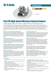
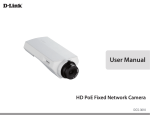
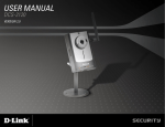
• D-Link DCS-5610 PTZ PoE Network Camera
• CAT5 Ethernet Cable
• Power Adapter
• Manual and Software on CD
• Quick Install Guide
• Camera Mounting Bracket
Note: Using a power supply with a different voltage than the one
included with your product will cause damage and void the warranty
for this product.
If any of the above items are missing, please contact your reseller.
System Requirements
• Windows® XP or Windows Vista®
• At least 256MB of memory (512MB recommended)
• An available Ethernet connection
• Internet Explorer 6.x or higher Internet Web Browser
• VGA card resolution: 800x600 or above
• CPU: 1.7GHz or above processor (2.8GHz plus processor with 512MB memory and a 32MB video card is required for
multiple camera viewing and recording in IP surveillance program)
D-Link DCS-5610 User Manual
Section 1 - Product Overview
Introduction
The D-Link DCS-5610 PTZ (Pan, Tilt, and Zoom) PoE Network Camera is a full featured surveillance system that connects to an Ethernet,
Fast Ethernet or broadband Internet connection to provide remote high-quality 2-Way Full Duplex audio, and 2.6x optical and 4x digital
zoom for greater clarity and detail from your recordings. The DCS-5610 is the latest product added to the D-Link SECURICAM Network
line. The DCS-5610 PTZ PoE Network Camera differs from a conventional PC Camera because it is a stand-alone system with a builtin CPU and Web server, capable of solving demanding security and home/office monitoring needs. The PTZ PoE Network Camera can
be accessed remotely, and controlled, from any PC or notebook computer over the Internet from anywhere in the world. The simple
installation procedures, along with the built-in Web-based interface offer easy integration to your network environments.
Note: Use of audio or video equipment for recording the image or voice of a person without their knowledge and
consent is prohibited in certain states or jurisdictions. Nothing herein represents a warranty or representation
that the D-Link product provided herein is suitable for the end-user’s intended use under the applicable laws of
his or her state. D-Link disclaims any liability whatsoever for any end-user use of the D-Link product, which fails
to comply with applicable state, local, or federal laws.
D-Link DCS-5610 User Manual
Section 1 - Product Overview
Features
• Motorized Pan and Tilt Operation - The DCS-5610 has a pan and tilt function that can expand your viewing area to
cover a wide 300o angle side-to-side and a 90o angle up and down.
• CCD Sensor - The DCS-5610 comes with a high quality CCD sensor that is superior to CMOS type sensor. The variable
focus glass lens will facilitate the use of the DCS-5610 providing crystal clear and sharp images. You can view up to
30 frames per second of live motion video with 470 TV lines of resolution.
• Broad Range of Applications - With today’s high-speed Internet services, the PTZ PoE Network Camera can provide
the ideal solution for live video images and audio over the Intranet and Internet for remote monitoring. The DCS-5610
allows remote access from your Web browser for live image viewing with audio, and allows the administrator to manage
and control the PTZ PoE Network Camera anytime and anywhere in the world. Apply the Network Camera to monitor
various objects and places such as homes, offices, banks, hospitals, child-care centers, amusement parks and other
varieties of industrial and public monitoring. The PTZ PoE Network Camera can also be used for intruder detection with
its motion-detection mode, capture still images and video images for archiving, and many more applications such as
sending images to an FTP server or configuring for E-mail alerts. The DCS-5610 features 2-way Full-Duplex audio with
a built-in microphone that lets you remotely monitor and record audio with your video. With the addition of optional
speakers (not included), you can have 2-way Full-Duplex audio communication with the people you are viewing. The
DCS-5610 also features 2.6x optical and 4x digital zoom for closer viewing.
• Supports a Variety of Protocols - In addition, the DCS-5610 supports a variety of platforms including RTSP, FTP,
SMTP, NTP, and HTTP. The camera also supports UPnP and DDNS. DDNS allows your camera to be accessed using a
static host name rather than an IP address. UPnP will allow users of Windows® XP to install the camera with a single
mouse click.
D-Link DCS-5610 User Manual
Section 1 - Product Overview
• Audio Out - Connect a speaker to the camera so that a person in front of the camera can hear the person on the other
end of the communication.
• Web Configuration - Using a Web browser, administrators can configure and manage the PTZ PoE Network Camera
directly from its own Web page via the Intranet or the Internet. Up to 20 user names and passwords are permitted,
with privilege settings controlled by the administrator.
• Powerful Surveillance and Remote Monitoring Utility - The powerful D-ViewCam software application assigns an
administrator with a pre-defined user ID and password who can modify the PTZ PoE Network Camera settings from
the remote site via the Intranet or the Internet. Administrators are allowed to monitor the image, record the image to
a hard drive, take snapshots, and more.
• Connection to External Devices - Supporting auxiliary Input/Output connectors, you can connect the PTZ PoE Network
Camera to a variety of external devices such as IR-sensors, switches and alarm relays. Combined with programmable
alarming equipment, you can develop a variety of security applications that are triggered on alarm-based events. The
PTZ PoE Network Camera provides an industry standard in/out external connector for connectivity.
• Internal/External Microphone - The SECURICAM Network DCS-5610 allows you to monitor video as well as audio
through the web browser. You have the option of using the DCS-5610’s integrated microphone or your own external
microphone using the connection located at the rear of the unit.
Note: Use of audio or video equipment for recording the image or voice of a person without their knowledge and consent is prohibited in
certain states or jurisdictions. Nothing herein represents a warranty or representation that the D-Link product provided herein is suitable
for the end-user’s intended use under the applicable laws of his or her state. D-Link disclaims any liability whatsoever for any end-user use
of the D-Link product, which fails to comply with applicable state, local, or federal laws.
D-Link DCS-5610 User Manual
Section 1 - Product Overview
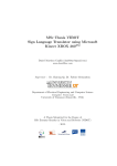
Hardware Overview
Connections
Reset Button
Reset will be initiated when the reset
button is pressed once and held 30
seconds until the Power LED flashes
through its cycle twice.
DC Power Connector
The DC power input connector is located on
the DCS-5610 Network Camera’s back panel
and is labeled 12V DC with a single socket to
supply power to the Network Camera.
MIC On/Off Switch
Used to turn the microphone on or
off.
Ethernet Cable Connector (PoE)
The Network Camera’s back panel features an RJ-45 connector for
connections to 10Base-T Ethernet cabling or 100Base-TX Fast Ethernet
cabling. This network port supports the NWay protocol, allowing the
Network Camera to automatically detect or negotiate the transmission
speed of the network. The Ethernet port can also be used to power the
camera by using a PoE switch.
Audio Out Connector
The DCS-5610 provides an Audio Out connector to be
used for 2-way audio. Speakers (not included) may be
connected to the camera to provide audio for 2-way
communication.
I/O Connector
Microphone Connector
The DCS-5610 Network Camera has an internal
microphone built-in. However, you have the option of
using an external microphone by plugging it into the
microphone connector.
D-Link DCS-5610 User Manual
The DCS-5610 provides a terminal block with two pairs of connectors
situated on the back panel. One pair is for input and the other is for
output. The I/O connectors provide the physical interface to send and
receive digital signals to and from a variety of external devices.
Section 1 - Product Overview
Hardware Overview
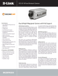
LEDs
Power/MIC LED
The power LED is at the front base of the camera.
As soon as the power adapter is connected to the
camera, the LED will turn red.
D-Link DCS-5610 User Manual
Activity LED
Once a connection has been established via Ethernet
port, the Activity LED will turn solid green. If traffic is
passing to the camera the Activity LED will blink. If
no Ethernet connection is detected the Activity LED
will not light up.
Section 1 - Product Overview
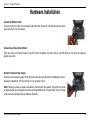
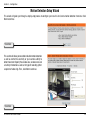
Hardware Installation
Connect the Ethernet Cable
Connect an Ethernet cable to the network cable connector located on the Network Camera’s back
panel and attach it to the network.
Connect Using Power-Over-Ethernet
Once you connect an Ethernet cable to your PoE switch or adapter, the Power LED on the DCS-5610 will turn green to indicate a
proper connection.
Attach the External Power Supply
Attach the external power supply to the DC power input connector located on the Network Camera’s
back panel (labeled DC 12V) and connect it to an AC power outlet.
Note: When you have a proper connection, the LED will turn green. The light may cycle
on and off and your computer may show an intermittent loss of connectivity, this is normal
until you have configured your Network Camera.
D-Link DCS-5610 User Manual
10
Section 1 - Product Overview
The Network Camera comes with a camera mounting bracket with a swivel ball screw head that can be attached to the Network Camera
bottom socket cavity. Attach the camera stand to the Network Camera and station it for your application. There are holes located in
the base of the mounting bracket allowing the Network Camera to be mounted to the ceiling, or any wall securely.
Socket for camera mounting bracket
D-Link DCS-5610 User Manual
11
Section 2 - Installation
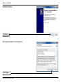
Software Installation
Turn on the computer and Insert the D-Link DCS-5610 Autorun CD in the CD-ROM drive. The step-by-step instructions that follow
are shown in Windows® XP. The steps and screens are similar for the other Windows operating systems.
Click Installation Wizard
If the CD Autorun function does not automatically start on your computer, click Windows Start > Run. In the Run command box type
“D:\DCS5610.exe”, where D: represents the drive letter of your CD-ROM. If it does start, proceed to the next screen.
D-Link DCS-5610 User Manual
12
Section 2 - Installation
Click Next to continue.
Click Next
Click I Agree to accept the License Agreement.
Click I Agree
D-Link DCS-5610 User Manual
13
Section 2 - Installation
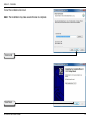
To start the installation click Install.
Note: The installation may take several minutes to complete.
Click Install
Click Finish
D-Link DCS-5610 User Manual
14
Section 3 - Configuration
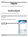
Configuration
This section will show you how to configure your new D-Link Network Camera using the Installation Wizard.
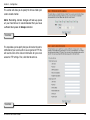
Setup Wizard Configuration
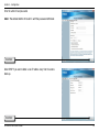
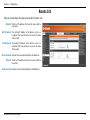
Click on the D-Link Installation Wizard icon that was created in your Windows Start menu.
The Setup Wizard will appear and show the MAC address of the DCS-5610 and an IP Address (which may or may not be correct
depending on what you have your DCS-5610 connected to). If you have a DHCP server on your network, there will be a valid IP
Address displayed here.
Note: A DHCP server is a device that supplies the same IP address.
Click Manual Setup
D-Link DCS-5610 User Manual
15
Section 3 - Configuration
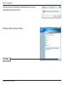
Enter the admin ID and password.
Note: The default Admin ID is admin with the password left blank.
Click Next
Select DHCP if you want to obtain a new IP address every time the camera
boots up.
Click Next
D-Link DCS-5610 User Manual
16
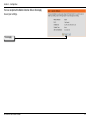
Section 3 - Configuration
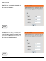
Choose UPnP Port Forwarding if your router supports it, otherwise choose
Manual to enter your port numbers manually. Click Next to continue.
Click Next
Enable DDNS and setup your DDNS service here, if you have subscribed to a
DDNS service. Click Next to continue.
Click Next
D-Link DCS-5610 User Manual
17
Section 3 - Configuration
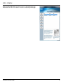
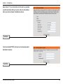
If you want to access the DCS-5610 via mobile phone, click Yes and the
video resolution will be set to 176x144.
Click Apply to apply the settings to the device.
Click Apply
D-Link DCS-5610 User Manual
18
Section 3 - Configuration
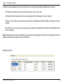
Double-click the DCS-5610 to launch the camera’s web configuration page.
D-Link DCS-5610 User Manual
19
Section 3 - Configuration
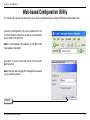
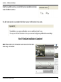
Web-based Configuration Utility
This section will show you how to configure your new D-Link Network Camera using the Web-based Configuration Utility.
To access the configuration utility, open a web-browser such
as Internet Explorer and enter the IP address of your Network
Camera (http://192.168.0.120)
Note: In the example, this address is 192.168.0.120.
Your address may differ.
Type Admin in the user name field and leave the password
blank by default.
Note: You may refer to page 51 to change the password
for your admin account.
Click OK
D-Link DCS-5610 User Manual
20
Section 3 - Configuration
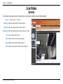
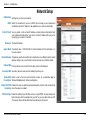
Live Video
Camera
This section shows your camera’s live video. You can control your settings using the buttons below.
Zoom: “-” zooms out, and “+” zooms in.
Pan Speed: Select the speed at which the camera will pan.
Tilt Speed: Select the speed at which the camera will tilt.
Zoom Speed: Select the speed at which the camera will zoom or focus.
Pan: Pans the camera one full cycle.
Stop: Stops movement of the camera during pan.
Patrol: Enables the patrol feature. Refer to page 47.
Go to: Select a preset position where the camera will point.
D-Link DCS-5610 User Manual
21
Section 3 - Configuration
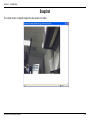
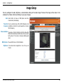
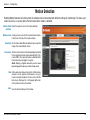
Snapshot
This section shows a snapshot image from your camera’s live video.
D-Link DCS-5610 User Manual
22
Section 3 - Configuration
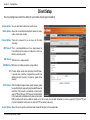
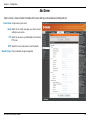
Client Setup
You may configure and select the setting for your media streaming and recording
Stream Options: You can select which video stream profile to use.
Media Options: Allows the user to determine whether to receive only video,
audio, or both video & audio.
Protocol Options: There are 4 protocols for you to choose for the video
streaming.
UDP Protocol: This is recommended because it is an ideal protocol for
transmitting real-time audio and video data, which can
tolerate some lost packets.
UDP Unicast: Will stream to a single computer.
UDP Multicast Will stream to multiple computers using multicast.
TCP: Provides higher quality video streaming than UDP does.
It provides error correction and guarantees packet to be
delivered to client. However, transmission speed will be
reduced.
HTTP Protocol: Offers the highest image and video quality. However, packet
losses will diminish image quality when bandwidth becomes
restricted. If the network is protected by a firewall and it
opens HTTP port (80) only, HTTP protocol must be selected.
In this mode, audio is disabled and only video can be viewed.
UDP connections will not be available to remote users if all four ports have not been forwarded (as shown on page 32). Only the HTTP port
must be forwarded for remote users to make an HTTP connection (video only).
Record Options: Allows the user to specify a destination folder and prefix filename for the recorded video.
D-Link DCS-5610 User Manual
23
Section 3 - Configuration
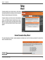
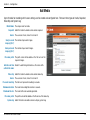
Setup
Wizard
To quickly configure your internet camera, click Internet
Connection Setup Wizard or click Manual Internet Connection
Setup to manually configure your internet camera.
To quickly configure your internet camera’s motion detection
settings, click Motion Detection Setup Wizard and skip to
page 29. If you want to enter your settings without running
the wizard, click Manual Motion Detection Setup and skip to
page 39.
Internet Connection Setup Wizard
This wizard will guide you through a step-by-step process to configure your new D-Link Camera and connect the camera to the
internet. Click Next to continue.
Click Next
D-Link DCS-5610 User Manual
24
Section 3 - Configuration
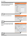
Select DHCP if you are unsure which settings to pick. Click
Next to continue and skip to page 27.
Click Next
Select PPPoE if the camera is directly connected to the Internet
through a DSL modem, and the ISP (Internet Service Provider)
requires you to use PPPoE for the Internet connection. Click
Next to continue and skip to Step 2 on page 26.
Click Next
D-Link DCS-5610 User Manual
25
Section 3 - Configuration
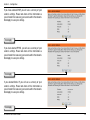
Select Static IP if your Internet Service Provider has provided
you with connection settings, or you wish to set a static address
within your home network. Click Next to continue.
Click Next
If you have selected PPPoE, enter your username and password.
Click Next to continue.
Click Next
D-Link DCS-5610 User Manual
26
Section 3 - Configuration
If you have a Dynamic DNS account and would like the camera
to update your IP address automatically, enable DDNS and enter
your host information. Click Next to continue.
Click Next
Enter a name for your camera and click Next to continue.
Click Next
Configure the correct time to ensure that all events will be
triggered, captured and scheduled at the right time. Click Next
to continue.
Click Next
D-Link DCS-5610 User Manual
27
Section 3 - Configuration
If you have selected DHCP, you will see a summary of your
camera’s settings. Please note down all this information as
you will need it for accessing your camera within the network.
Click Apply to save your settings.
Click Apply
If you have selected PPPoE, you will see a summary of your
camera’s settings. Please note down all this information as
you will need it for accessing your camera within the network.
Click Apply to save your settings.
Click Apply
If you selected Static IP, you will see a summary of your
camera’s settings. Please note down all this information as
you will need it for accessing your camera within the network.
Click Apply to save your settings.
Click Apply
D-Link DCS-5610 User Manual
28
Section 3 - Configuration
Motion Detection Setup Wizard
This wizard will guide you through a step-by-step process to configure your new D-Link Camera motion detection functions. Click
Next to continue.
Click Next
This section will allow you to enable or disable motion detection
as well as control the sensitivity or your camera’s ability to
detect movement. Specify the window area, window name and
sensitivity of detection as well as the type of recording (either
snapshot of video clip). Then, click Next to continue.
Click Next
D-Link DCS-5610 User Manual
29
Section 3 - Configuration
This section will allow you to specify the time and date your
camera records motion.
Note: Recording camera footage will take up space
on your hard drive. Its recommended that you have
sufficient disk space for Always function.
Click Next
This step allows you to specify how you will receive the events
notification of your camera, either via using email or FTP. You
will need to enter all the relevant information for your email
account or FTP settings. Then, click Next to continue.
Click Next
D-Link DCS-5610 User Manual
30
Section 3 - Configuration
You have completed the Motion Detection Wizard. Click Apply
to save your settings.
Click Apply
D-Link DCS-5610 User Manual
31
Section 3 - Configuration
Network Setup
LAN Settings: Settings for your local area network.
DHCP: Select this connection if you have a DHCP server running on your network and
would like a dynamic IP address to be updated to your camera automatically.
Static IP Client: You may obtain a static or fixed IP address and other network information from
your network administrator for your camera. A static IP address will ease you for
accessing your camera in the future.
IP Address: The fixed IP address.
Subnet Mask: The default value is “255.255.255.0.” Used to determine if the destination is in
the same subnet.
Default Gateway: The gateway used to forward frames to destinations in a different subnet. Invalid
gateway settings may cause the failure of transmissions to a different subnet.
Primary DNS: Primary domain name server that translates names to IP addresses.
Secondary DNS: Secondary domain name server to backup the primary one.
Enable UPnP Allows a user to find, view and control this camera via a presentation page or
Presentation: “Network Neighborhood” without configuration.
Enable UPnP Port Enables the camera to add the port forwarding entry into the router automatically
Forwarding: when this option is enabled.
PPPoE Settings: Enable this setting if your ISP (DSL service) is using PPPoE. You may already have
both Username and Password given by your ISP, or you may check with your ISP.
The Connect Status will be determined automatically by the system.
D-Link DCS-5610 User Manual
32
Section 3 - Configuration
HTTP: You may configure two HTTP ports for your camera. HTTP ports allow you to connect to the camera via a standard web browser. These ports
can be set to a number other than the default TCP ports 80 and 8080. A corresponding port must be opened on the router. For example, if
the port is changed to 1010, users must type in the web browser “http://192.168.0.100:1010” instead of “http://192.168.0.100”.
Authentication: Authentication: Choose either Basic where the password is not encrypted, or Digest where the password is encrypted during the transmission
to the web server.
HTTP Port: The default value is 80.
Secondary HTTP The default value is 8080.
Port: After you have enabled the Authentication, you will need to configure and use the access name to access your video file. For example,
http://camera ip/video.mjpg (video.mjpg is the Access name, you can modify it here)
Access name for The default name is video.mjpg.
stream1:
Access name for The default name is video2.mjpg.
stream2:
FTP Port: Default port is 21. If you want to change the port number, you will need to specify the port when connecting to the FTP server. For example
FTP://68.5.1.81:60 (if you use port 60 for your FTP server)
RTSP Streaming: This setting enables you to connect to a camera by using streaming mobile device(s), such as a mobile phone or PDA.
Authentication: Choose either Basic where the password is not encrypted, or Digest where the password is encrypted during the transmission to the web
server. After you have enabled the Authentication, you will need to configure and use the access name to access your video file. RTSP://
camera ip/live.sdp (live.sdp is the default access name, you can modify it here)
Access name for The default name is live.sdp.
stream1:
Access name for The default name is live2.sdp.
stream2:
D-Link DCS-5610 User Manual
33
Section 3 - Configuration
RTSP port: The port number that you use for RSTP streaming, the default port number is 554. RTP (Real Time Protocol) Port is used to streaming
audio and video while RTCP (Real Time Control Protocol) port is used to monitor QoS of RTP stream.
Note: RTP video port and RTP audio port must be an “even” number. The numbers of RTCP video port and RTCP audio
port must equal to the numbers of RTP video port and RTP audio port, plus one repetitively
RTP port for video: Default port number is 5556.
RTCP port for video: Default port number is 5557.
RTP port for audio: Default port number is 5558.
RTCP port for audio: Default port number is 5559.
You may choose to enable multicast for your camera audio and video streaming so that your cameras (sources) and the receivers (clients)
can establish the connection to send and receive contents.
Multicast group An IP Multicast group address is used to send and receive content. Sources use this group address as the destination address while
address: sending their data packets. Receivers use this group address to inform the network that they are interested in receiving packets sent to
that group.
For example, if some content is associated with group 239.1.1.1, the source will send data packets destined to 239.1.1.1. Receivers for
that content will inform the network that they are interested in receiving data packets sent to the group 239.1.1.1. The receiver “joins”
239.1.1.1. The Multicast address ranges from 224.0.0.0 to 239.255.255.255, or, equivalently, 224.0.0.0/4
Multicast video port: Default port number is 5560, or please choose between 1024 and 65534.
Multicast RTCP video Default port number is 5561, or please choose between 1024 and 65534.
port:
Multicast audio port: Default port number is 5562, or please choose between 1024 and 65534.
Multicast RTCP audio Default port number is 5563, or please choose between 1024 and 65534.
port:
Multicast TTL Set a Time to Live(TTL) value for multicast packet, please choose between 1 and 255.
{1~255]:
D-Link DCS-5610 User Manual
34
Section 3 - Configuration
Dynamic DNS
DDNS (Dynamic Domain Name Server) will hold a DNS host name and synchronize the public IP address of the modem when it has
been modified. The username and password are required when using the DDNS service.
Enable DDNS: Click to enable the DDNS function.
Server Name: Select your Dynamic DNS provider from the pull
down menu.
Host Name: Enter the host name of the DDNS server.
Username: Enter your username or e-mail used to connect to
the DDNS
Password: Enter your password used to connect to the DDNS
server.
Status: Indicate the connection status, automatically
determined by the system.
D-Link DCS-5610 User Manual
35
Section 3 - Configuration
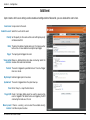
Image Setup
You may configure the color, brightness, and orientation settings of the video image. Preview of the image will be shown in the
window of Live Video. Click Save Settings to save your changes.
Color: Select either for Color or B/W (black and white,
monochrome) video display.
Power line You may need to choose 50 or 60 Hz frequency; and
frequency: nonetheless maintain the system operation at a basic
50 Hz frequency.
Video orientation: Two options. Flip will vertically rotate the video while
Mirror will horizontally rotate the video. You may check
both options if the camera is being installed upside
down.
White balance: Choose either Auto or Fix white balance.
Brightness: It has eleven levels ranged from -5 to +5 for you to
choose.
D-Link DCS-5610 User Manual
36
Section 3 - Configuration
Audio and Video
Two different settings for two video streams (stream 1 and stream 2) can be configured here. You may configure one setting for
computer display and the other one for mobile display.
Mode: It can be either JPEG or MPEG4. In JPEG mode, the video
frames are independent. However, MPEG4 consumes
much less network bandwidth than JPEG.
Frame Size: Frame Size: Three options exist for the sizes of the video
display. You can select between 176x144, 352x240, or
640x480. It is recommended using 176x144 for mobile
viewing and 640x480 for computer viewing.
Maximum frame 1 is the minimum value while 30 is the maximum value.
rate: It is recommended choosing 30 for computer viewing
and 5 for mobile viewing.
Video quality: This limits the maximal refresh frame rate, which can
be combined with the “Fixed quality” to optimize the
bandwidth utilization and video quality. If the User
wants to fix the bandwidth utilization regardless of the
video quality, choose “Constant bit rate” and select the
desired bandwidth.
Mute: Select this if you want to switch off the sound.
Internal Select from the list to set internal microphone input gain.
microphone input It is necessary to find the optimum gain that transmits
gain: the best audio to whoever is listening.
Note: dB stands for decibels, unit of audio
measurement. More decibels as a positive value
indicates that the sound is louder, while more
decibels as a negative value indicates that the
sound is quieter.
D-Link DCS-5610 User Manual
37
Section 3 - Configuration
External Select from the list to set external microphone input gain.
microphone
input:
Audio type: AAC (Advanced Audio Coding): A wide band audio coding algorithm that exploits two primary coding strategies to dramatically reduce the
amount of data needed to convey high-quality digital audio. Select a higher bit rate number for better audio quality.
GSM-AMR: A standard adapted audio codec by the 3GPP video (3rd Generation Partnership Project). It is an Adaptive Multi Rate-Narrow Band (AMRNB) speech codec. Select a higher bit rate number for better audio quality.
AAC bit rate: Please select from the list, higher bit rate means higher audio quality but it takes more network bandwidth to transmit.
GSM-AMR bit Please select from the list, higher bit rate means higher audio quality but it takes more network bandwidth to transmit.
rate:
D-Link DCS-5610 User Manual
38
Section 3 - Configuration
Motion Detection
Enabling Motion Detection will allow up to three windows that can be created with different settings for monitoring. This allows your
camera to serve as a security device that will record when motion is detected.
Enable motion Check this option to turn on the motion detection.
detection:
Window name: Create your own name for the monitored area/ window.
It will show at the top of the motion window.
Sensitivity: Set the measurable difference between two sequential
images that would indicate motion.
Percentage: Set the amount of motion in the window being monitored
that is required to initiate a motion detected alert. If this
is set to 100%, this means that motion is detected within
the whole window to trigger a snapshot.
Note: Setting a higher sensitivity and a lower
percentage will make any motion more easily.
New: Click to add a new window. A maximum of three motion
windows can be opened simultaneously. Use your
mouse to drag the window frame to re-size or the title
bar to move. Clicking on the ‘x’ at the upper right corner
of the window will close the window.
Save: Save the related settings of that window.
D-Link DCS-5610 User Manual
39
Section 3 - Configuration
Time and Date
From this section, you may automatically or manually configure, update and maintain the internal system clock for your camera.
Current Server Will be determined by the system.
Time:
Time Zone: Select your time zone from the drop-down menu.
Enable Daylight Select this to enable the daylight saving time.
Saving:
Daylight Saving You may configure the daylight saving date and time.
Dates:
Automatic Time Enable this feature to obtain time configuration
Configuration: automatically from NTP server.
NTP Server: Network Time Protocol (NTP) synchronizes the DCS5610 with an Internet time server. Choose the one that
is closest to your location.
Update Interval: The time interval for updating the time information
from NTP server.
Set the date and This option allows you to set the time and date
time manually: manually.
Copy Your This will synchronize the time information from your
Computer’s Time PC.
Settings:
D-Link DCS-5610 User Manual
40
Section 3 - Configuration
Event Setup
There are three sections in Event Setup page. They are Event, Server and Media. Click Add to pop up a window to add a new item of
event, server or media. Click Delete to delete the selected item from the pull-down menu of event, server or media. Click on the item
name to pop up a window for modifying. You can add up to three events, five servers and five medias.
D-Link DCS-5610 User Manual
41
Section 3 - Configuration
Add Server
Up to 5 servers, where will store the media with its own settings can be created and configured here.
Server Name: Unique name of your server.
Email: Select this to enable and apply your email account
setting for your camera.
FTP: Select this to access a granted folder on the external
FTP server.
HTTP: Select this to use a web server to store the media.
Network Storage: Only one network storage is supported.
D-Link DCS-5610 User Manual
42
Section 3 - Configuration
Add Media
Up to 5 media for recording with its own settings can be created and configured here. There are three types of media, Snapshot,
Video Clip and System Log.
Media Name: The unique name for media.
Snapshot: Select this feature to enable camera to take snapshot.
Source: The source of stream, stream1 or stream2.
Send pre-event The number of pre-event images.
image(s) [0~7]:
Send post-event The number of post-event images.
image(s) [0~7]:
File name prefix: The prefix name will be added on the file name of the
snapshot images.
Add date and time Check it to add timing information as file name suffix.
suffix to file name:
Video clip: Select this feature to enable camera to take video clip.
Source: The source of stream, stream1 or stream2.
Pre-event recording: The interval of pre-event recording in seconds.
Maximum duration: The maximal recording file duration in seconds.
Maximum file size: The maximal file size would be generated.
File name prefix: The prefix name will be added on the file name of the video clip.
System log: Select this feature to enable camera to display system log.
D-Link DCS-5610 User Manual
43
Section 3 - Configuration
Add Event
Up to 3 events with its own settings can be created and configured here. Meanwhile, you can schedule the events here.
Event name: Unique name for the event.
Enable this event: Select this to activate this event.
Priority: Set the priority for this event and the event with higher priority
will be executed first.
Delay: The delay time before checking next event. It is being used for
both events of motion detection and digital input trigger.
Trigger: The input type that triggers the event.
Video motion Motion is detected during live video monitoring. Select the
detection: windows that need to be monitored.
Periodic: The event is triggered in specified intervals. The unit of trigger
interval is minute.
Digital input: External trigger input to the camera.
System boot: The event is triggered when the system boot up.
Time: Either “Always” or input the time interval.
Trigger D/O: Check it to trigger digital output for specific seconds when
event is triggered. The default actions are triggering the D/O
and storing the media on a CF card.
Move to preset If there is a server(s), user can select the available server(s)
location: from Move to preset location.
D-Link DCS-5610 User Manual
44
Section 3 - Configuration
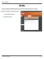
Recording
Here you can configure and schedule the recording. You may add new entry or delete an existing entry via this page.
Recording entry: Available entry(s) is displayed here with its details.
Add: Click this button to add new entry.
Delete: Delete an existing entry.
D-Link DCS-5610 User Manual
45
Section 3 - Configuration
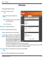
Add Recording
You can add and configure an entry here.
Recording entry The unique name of the entry.
name:
Enable this Select this to enable the recording function.
recording:
Priority: Set the priority for this entry and the entry with higher
priority will be executed first.
Source: The source of stream.
Recording schedule: Scheduling the recording entry.
Recording settings: Configuring the setting for the recording.
Destination: Select the folder where will store the recording file.
Total cycling Please input a HDD memory volume between 1MB and
recording size: 200GB for recording space. The recording data will
replace the oldest one when total recording size exceeds
this value. For example, if each recording file is 6MB, and
the total cycling recording size is 600MB, then camera
will recording 100 files to the specified location (folder).
And then the camera will delete the oldest file and create new file for cycling recording.
Please notice that if the HDD empty space is not enough, the recording will stop. Before you setup this option please make sure you HDD
have enough space and it is better not to save other files in the same folder as recording files.
Size of each file for File size for each recording file. You may input the value in the range of 200-6000.
recording:
File Name Prefix: The prefix name will be added on the file name of the recording file(s).
D-Link DCS-5610 User Manual
46
Section 3 - Configuration
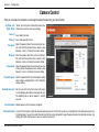
Camera Control
Here you can preset the locations and change the default location for your home button.
Up, Down, Left, “Home” aims the camera to the center, where as the
Right, Home: other buttons aim the camera accordingly.
Zoom (-): Zoom widely function.
Zoom (+): Zoom telescopically function
Pan Speed: Select the speed at which the camera will pan for a
full cycle from the pull down menu. Select a value
between -5 and +5, -5 being the slowest setting.
Tilt Speed: Select the speed at which the camera will tilt for a
full cycle from the pull down menu. Select a value
between -5 and +5, -5 being the slowest setting.
Zoom Speed: Select the speed at which the camera will zoom for
a full cycle from the pull down menu. Select a value
between -5 and +5, -5 being the slowest setting.
Pan/patrol speed: Select the speed at which the camera will pan during
patrol. Select a value between 1 and 5, 1 being the
slowest setting.
Dwelling time (sec): Set the value of time that the camera will remain
on each preset position before moving to the next.
The dwelling time can be set between 1 and 255
seconds.
Preset locations: Desired positions that have been configured.
Selected locations: To use the Patrol feature, select the desired preset positions from the Preset Locations list and add them to the Selected Locations list
by clicking Select. You can then select the order in which the camera will patrol through the preset locations by selecting a location and
clicking UP or DN. Click Remove to remove a location from the list.
D-Link DCS-5610 User Manual
47
Section 3 - Configuration
Current Enter a name for the position at which you would like to preset the DCS-5610. Click Add to add the new preset position to the Preset
Position: Locations list.
Preset A pull-down menu that contains all the preset locations. You can delete a preset position by selecting it and clicking Delete.
Position:
Home Allow users to set a new home position or default back to the original.
Location:
D-Link DCS-5610 User Manual
48
Section 3 - Configuration
Access List
Here you can configure the access permissions for each user.
Allow list: The list of IP addresses that have the access right to
the camera.
Start IP address: The starting IP Address of the devices (such as a
computer) that have permission to access the video
of the camera.
End IP address: The ending IP Address of the devices (such as a
computer) that have permission to access the video
of the camera.
Delete allow list: Remove the customized setting from the Allow List.
Deny list: The list of IP addresses that have no access right to
the camera.
Delete deny list: Remove the customized setting from the Delete List.
D-Link DCS-5610 User Manual
49
Section 3 - Configuration
DI and DO
The I/O connector provides the physical interface for digital output (DO) and digital input (DI) that is used for connecting such external
alarm devices as IR-Sensors and alarm relays to the PTZ IP camera.
DI and DO: Setting for both Digital input signal and digital output
signal can be configured here.
Digital input trigger Please select from “High” or “Low” for digital input
condition: trigger condition. When external device connect to
the digital input pins, the state of the voltage will be
monitored. (Max. Input 500mA, 12Vdc)
Digital output: Select Grounded or Open to define normal status of the
digital output. The camera will show whether the trigger
is activated or not.
D-Link DCS-5610 User Manual
50
Section 3 - Configuration
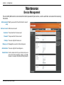
Maintenance
Device Management
You can modify both camera’s name and administrator’s password of your camera, as well as add more user accounts for accessing
the camera.
Admin password Modify a password for the administrator’s account.
setup:
Add user account: Add new user account.
Username: The username for the new account.
Password: The password for the new account.
Privilege: The access right for the new user.
Manage user: Managing the accounts for the existing users.
Authentication: The access right for the existing users.
Camera Name: Create a unique name for your camera and you can
access the camera using this name in your webbrowser. For example: http://DCS-5610 (By default).
D-Link DCS-5610 User Manual
51
Section 3 - Configuration
Backup and Restore
You can turn off the front panel LED, restore factory default settings and reboot the camera.
Turn off the LED Check this option to turn off the LED next to the lens.
indicator: This will prevent anyone from observing the operation
of the IP Camera.
Restore: Click the button will reset the camera back to its factory
default settings. This will remove all the configuration
settings that were made previously.
Reboot: Click the button will restart the camera.
D-Link DCS-5610 User Manual
52
Section 3 - Configuration
Firmware Update
Your current firmware version and date will be displayed on your screen. You may go to the D-Link Support page to check for the
latest firmware version available.
To upgrade the firmware on your DCS-5610, please download and save the latest firmware version from the D-Link Support page to
your local hard drive. Locate the file on your local hard drive by clicking the Browse button. Then, open the file and click the “Upload”
button to start the firmware upgrade.
Current firmware It will be automatically determined and displayed by the
version: system.
Current firmware It will be automatically determined and displayed by the
date: system.
File Path: Locate the file (upgraded firmware) on your hard drive
using the browse feature.
Upload: Start uploading and upgrading the new firmware to your
camera.
D-Link DCS-5610 User Manual
53
Section 3 - Configuration
Status
Device Info
This page displays all the details information about your device and network connection.
D-Link DCS-5610 User Manual
54
Section 3 - Configuration
Logs
This page displays the log information of your camera. You can configure a remote log server so that you can view your log details
remotely.
Enable remote log: Enabling this feature so that the camera can send camera
log files to a remote server.
Log server settings: Configure the setting for the log server.
IP Address: The IP address of the remote server.
Port: The port number of the remote log server. The default
port is 514.
Save: Save the setting.
Current Log: The system log file that displayed by the system. The
content of the file reveals useful information about
camera configuration and connectivity status after the
camera boots up.
D-Link DCS-5610 User Manual
55
Section 3 - Configuration
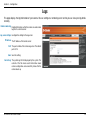
Help
D-Link DCS-5610 User Manual
56
Section 4 - D-ViewCam Installation
D-ViewCam Installation
D-ViewCam software is included for the administrator to manage up to 32 D-Link IP cameras remotely. The administrator can use the
software to configure the advances settings for the camera. D-ViewCam is a complete management tool and includes all configurative
settings.
Insert the CD-ROM into the CD-ROM drive. A menu screen will appear as shown below.
Click D-ViewCam
D-ViewCam provides English, Traditional Chinese and Simplified Chinese language
versions. Select a language version and click OK to continue.
Click OK
D-Link DCS-5610 User Manual
57
Section 4 - D-ViewCam Installation
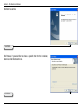
Click Next to continue.
Click Next
Click Browse if you would like to choose a specific folder for the installation,
otherwise click Next to continue.
Click Next
D-Link DCS-5610 User Manual
58
Section 4 - D-ViewCam Installation
Click Next to start the installation.
Note: The D-ViewCam installation process may take several minutes to
complete.
Click Next
Click Finish to complete the installation.
Click Finish
D-Link DCS-5610 User Manual
59
Section 4 - D-ViewCam Installation
Add a Camera
This section will show you how to start and add a camera to the D-ViewCam system.
To start D-ViewCam, select Start > All Programs > D-Link > D-Link
D-ViewCam.
Enter admin as the default username and leave the password blank. Click
/ OK to log into the system and access the Add Camera Wizard.
Note: Please refer to page 48 in the D-ViewCam user manual
to change your password.
D-Link DCS-5610 User Manual
60
Section 4 - D-ViewCam Installation
Welcome to the Add Camera Wizard. Use this wizard to add your cameras to the D-ViewCam system.
Note: Use the left or right arrow to navigate the wizard.
Click
/ Next to continue.
Click Next
D-Link DCS-5610 User Manual
61
Section 4 - D-ViewCam Installation
Choose which method to add your camera(s). You can choose Auto Discovery
to automatically search for your camera(s), or choose Add Manually to add your
camera(s) via the camera’s IP address. Click Next to continue.
If you choose Auto Discovery, the system will search all cameras that are located
on the same LAN with same subnet. The system will place all the cameras at the
default map called My Map. Click Next to continue.
If you choose Add Manually, enter the IP address or domain name, http port,
model name, camera ID and password.
Click the “?” button to auto detect the camera’s model name, then the model name
will appear in the Model Name box.
Click Next to continue.
D-Link DCS-5610 User Manual
62
Section 4 - D-ViewCam Installation
D-ViewCam shows the detected IP camera(s) information. You can choose and schedule the recording for each camera.
• 24/7 Continuous Recording: Continuously recording 24 hours a day, 7 days a week.
• 24/7 Motion Detection Recording: Continuously monitoring but ONLY recording when motion is detected.
• Office Hours Only: Continuously monitoring during office hours (08:00 AM to 06.00 PM) and ONLY recording when motion is
detected.
• Non-Office Hours Only: Continuously monitoring during non-office hours (06:00 PM to 08.00 AM) and ONLY recording when
motion is detected.
Note: Excluding 24/7 Continuous Recording, other schedule recording types can ONLY do recording when motion is
detected. Please refer to page 29 for more information.
Click Next to continue.
D-Link DCS-5610 User Manual
63
Section 4 - D-ViewCam Installation
Select Yes to add other camera(s), or select No if you have no additional camera(s)
to add. Click Next to continue.
The Add Camera wizard is now complete. Click Close to access the D-ViewCam’s main screen.
Your D-ViewCam Installation is Complete!
Note: Please refer to the D-ViewCam user manual for information
about using D-ViewCam.
D-Link DCS-5610 User Manual
64
Section 5 - Frequently Asked Questions
Frequently Asked Questions
This chapter provides solutions to problems that may occur during the installation and operation of the DCS-5610. Read the following
descriptions if you are having problems. (The examples below are illustrated in Windows® XP. If you have a different operating system,
the screenshots on your computer will look similar to the following examples.)
1. What is a PTZ PoE Network Camera?
PTZ PoE Network Camera Features
The PTZ PoE Network Camera is a stand-alone system connecting directly to an Ethernet or Fast Ethernet network. The PTZ PoE
Network Camera differs from a conventional PC Camera because it has an integrated system with built-in CPU and web-based
solutions, providing a low cost solution that can transmit high quality video images for monitoring. The PTZ PoE Network Camera
can be remotely managed, accessed and controlled from any PC/Notebook over an Intranet or Internet using a web browser.
2. What is the maximum number of users that can access DCS-5610 simultaneously?
The maximum number of users that can log onto the PTZ PoE Network Camera at the same time is 10. Please keep in mind the overall
performance of the transmission speed will be reduced if many users have logged on to the camera simultaneously.
3. What algorithm is used to compress the digital image?
The PTZ PoE Network Camera utilizes MPEG-4 simple profile or MJPEG Mode image compression technology providing high quality
images. MJPEG is a standard for image compression and it can be applied to various web browsers and application software without
installing any extra software
4. Can I capture still images from the PTZ PoE Network Camera?
Yes you can capture still images using the snapshot function.
D-Link DCS-5610 User Manual
65
Section 5 - Frequently Asked Questions
PTZ PoE Network Camera Installation
1. Can the PTZ PoE Network Camera be used outdoors?
The PTZ PoE Network Camera is not weatherproof. It needs to be equipped with a weatherproof case for outdoor use but it is not
recommended.
2. When physically connecting the PTZ PoE Network Camera to a network, what network cabling is required?
The PTZ PoE Network Camera uses Category 5 UTP cable allowing 10 Base-T and 100 Base-T networking solutions.
3. Can the PTZ PoE Network Camera be setup as a PC-cam on a computer?
No, the PTZ PoE Network Camera is used only on an Ethernet or Fast Ethernet network.
4. Can the PTZ PoE Network Camera be connected to the network if it consists only of private IP addresses?
The PTZ PoE Network Camera can be connected to a LAN with private IP addresses.
5. Can the PTZ PoE Network Camera be installed and work if a firewall exists on the network?
If a firewall exists on the network, port 80 is open for ordinary data communication. The DCS-5610 uses port 5002 for streaming
audio and port 5003 for streaming video. These ports (or the ports you have specified in the Advanced Tab in the Configuration
screen) need to be opened on the firewall.
6. Why am I unable to access the PTZ PoE Network Camera from a web browser?
If a router or firewall is used on the network, the correct ports for the DCS-5610 may not be configured on the router or firewall. To
correct the problem, you need to determine if the DCS-5610 is behind a router or firewall and if the router or firewall is properly
configured for the ports the DCS-5610 is using. Refer to Page 28 for help in opening the correct ports on a router or firewall for use
with the DCS-5610. Other possible problems might be due to the network cable. Try replacing your network cable. Test the network
interface of the product by connecting a local computer to the unit, utilizing a Ethernet crossover cable. If the problem is not solved
the PTZ PoE Network Camera might be faulty.
D-Link DCS-5610 User Manual
66
Section 5 - Frequently Asked Questions
7. Why does the PTZ PoE Network Camera work locally but not externally?
• This might be caused by network firewall protection. The setting of the firewall may need to be changed in order for the PTZ PoE Network
Camera to be accessible outside of your local LAN. Check with the Network Administrator for your network.
• Make sure that your PTZ PoE Network Camera isn’t conflicting with any Web server you may have running on your network.
• The default router setting might be a possible reason. Check that the configuration of the router settings allows the PTZ PoE Network
Camera to be accessed outside of your local LAN.
8. I connected the PTZ PoE Network Camera directly to a computer with a cross-over Ethernet cable and received a Windows error
upon running the installation Wizard?
• This Windows error will occur if the PTZ PoE Network Camera is connected to a computer that is not properly configured with
a valid IP address. Turn off DHCP from the Network Settings in Windows and configure the computer with a valid IP address
or connect the camera to a router with DHCP enabled.
• This error can also occur if the Installation Wizard icon is clicked on more than once from the setup wizard.
9. Noisy images occur. How can I solve the problem?
The video images might be noisy if the PTZ PoE Network Camera is used in a very low light environment. To solve this issue you
need more lighting.
10. The images appear to be of poor quality, how can I improve the image quality?
• Make sure that your computer’s display properties are set above 256 colors. Using 16 or 256 colors on your computer will
produce dithering artifacts in the image, making the image appear to be of poor quality.
• The configuration on the PTZ PoE Network Camera image display is incorrect. Through the Advanced>Image Setup section
of the Web management you need to adjust the image related parameters such as brightness, white balance and power line
frequency for fluorescent light.
D-Link DCS-5610 User Manual
67
Appendix B - Networking Basics
Networking Basics
Check your IP address
After you install your new D-Link adapter, by default, the TCP/IP settings should be set to obtain an IP address from a DHCP server
(i.e. wireless router) automatically. To verify your IP address, please follow the steps below.
Click on Start > Run. In the run box type cmd and click OK.
At the prompt, type ipconfig and press Enter.
This will display the IP address, subnet mask, and the
default gateway of your adapter.
If the address is 0.0.0.0, check your adapter installation,
security settings, and the settings on your access point.
Some firewall software programs may block a DHCP
request on newly installed adapters.
If you are connecting to a wireless network at a hotspot
(e.g. hotel, coffee shop, airport), please contact an employee or administrator to verify their wireless network settings.
D-Link DCS-5610 User Manual
68
Appendix B - Networking Basics
Statically Assign an IP address
If you are not using a DHCP capable gateway/access point, or you need to assign a static IP address, please follow the steps
below:
Step 1
Windows® XP - Click on Start > Control Panel > Network Connections.
Windows® 2000 - From the desktop, right-click My Network Places > Properties.
Step 2
Right-click on the Local Area Connection which represents your D-Link network adapter and select Properties.
Step 3
Highlight Internet Protocol (TCP/IP) and click Properties.
Step 4
Click Use the following IP address and enter an IP address that is on the same subnet as your network or the LAN IP address on
your access point.
Example: If the internet camera’s LAN IP address is 192.168.0.1, make your IP address
192.168.0.X where X is a number between 2 and 99. Make sure that the number you choose
is not in use on the network. Set Default Gateway the same as the LAN IP address of your
access point (192.168.0.1).
Set Primary DNS the same as the LAN IP address of your access point (192.168.0.1). The
Secondary DNS is not needed or you may enter a DNS server from your ISP.
Step 5
Click OK twice to save your settings.
D-Link DCS-5610 User Manual
69
Appendix C - Technical Specifications
Technical Specifications
Video Codec
MPEG4 / MJPEG
Audio Out
Yes
Audio Codec
GSM-AMR / MPEG-4 AAC
Mute Button
Slide switch for microphone mute (2 status)
PoE
Supported IEEE 802.3af standard Reset Button
Reset to factory default
Sensor
1/4” SONY progressive color CCD sensor
Dimension (WxHxD)
104 X 103.5 X 118 (mm)
SDRAM
32 Mbytes
Weight
319 (gram)
Flash Memory
8 Mbytes
Power Consumption
• Max 6W (estimate)
• Input: 100-240VAC, 50/60Hz
• Output: 12VDC, 1.5A
Lens
LAN
• 2.8-7.3mm zoom lens
• F1.9~F200 2.6x optical zoom (4x digital zoom)
• 10/100Base T ports x1
• IEEE 802.3 compliance
• IEEE 802.3u compliance
• Support Full-Duplex operations
• 802.3x Flow Control support for Full-Duplex mode
• Supported IEEE 802.3af standard (PoE)
MIC
6mm, -40 db ± 3db
I/O Connector
4pin-contact terminal block (1x input (2pins), 1x output(2pins)
D-Link DCS-5610 User Manual
Networking
Protocol
• IPV4, ARP, TCP, UDP, ICMP
• DHCP Client
• NTP Client (D-Link)
• DNS Client
• DDNS Client (D-Link)
• SMTP Client
• FTP Client
• HTTP Server
• Samba Client
• PPPoE
• UPnP Port Forwarding
• RTP
• RTSP
70
Appendix C - Technical Specifications
• RTCP
• IP filtering
• 3GPP
Ethernet
10/100M BaseT Fast Ethernet auto negotiation
Video
Algorithm Supported
MPEG4/MJPEG dual format compression simultaneously
JPEG for still image.
Features
• Adjustable image size and quality
• Time stamp and text overlay
• Three configurative motion detection windows
• Flip & mirror
Resolution
• 470 TV lines
• Up to 30 frames at 176x144
• Up to 30 frames at 320x240
• Up to 30 frames at 640x480
Low lux
1 Lux / F1.9
Sample rate
8/24/32K bps
Audio
Frequency
50 ~ 16000Hz
S/N ratio
More than 58dB
Mode
Full duplex 2-way audio communication
Directional
Omnidirectional
Microphone
Frequency
50 ~ 16000Hz
S/N ratio
6mm, - 40 dB + 3db
OS Support
Device
Windows 2000 / Windows XP / Windows Vista / 3GPP Mobile Phone
3A control
AGC, AWB, AES
Utility
Windows 2000 / Windows XP / Windows Vista
Electronic shutter
1/60(1/50)~1/100,000sec
Operation Temperature
0 to 40 °C (32 to 104°F)
D-Link DCS-5610 User Manual
71
Appendix C - Technical Specifications
Storage Temperature
- 20 to 70 °C (-4 to 158 °F)
Humidity
20-80% RH non-condensing
Emission (EMI), Safety & Other Certifications
• FCC
• CE
• C-Tick
Maximum wireless signal rate derived from IEEE Standard 802.11g, 802.11a and Draft 802.11n specifications. Actual data throughput will vary. Network conditions and environmental
factors, including volume of network traffic, building materials and construction, and network overhead, lower actual data throughput rate. Environmental conditions will adversely
affect wireless signal range.
2
Range varies depending on country’s regulation.
3
The DCS-5610 doesn’t include 5.25-5.35GHz & 5.47~5.725GHz.
1
D-Link DCS-5610 User Manual
72