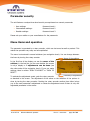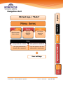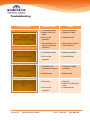
1
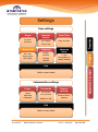
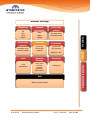
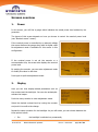
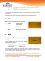
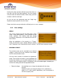
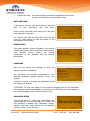
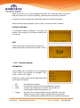
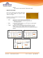
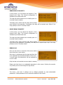
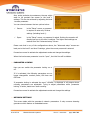
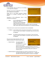
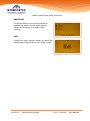
User Manual Display and Firmware Cleaning Generator with rotary encoder 2014-05-19 Mirtest ultrasonic systems Doc.nr.: xxxx.xxxx page 1 of 21 Table of contents Parameter security ............................................................................................................................... 3 Menu items and operation .................................................................................................................... 3 Status LEDs ......................................................................................................................................... 4 Navigation chart ................................................................................................................................... 5 Screens overview ................................................................................................................................. 8 1. 2. 3. 4. Power ................................................................................................................................ 8 Display .............................................................................................................................. 8 Info ................................................................................................................................... 9 Setup ................................................................................................................................ 9 1.4.1 User settings ........................................................................................................10 1.4.2 Advanced settings ................................................................................................12 1.4.3 Reseller settings ...................................................................................................13 Troubleshooting ..................................................................................................................................19 Maintenance and care ..........................................................................................................................20 Warranty ............................................................................................................................................20 Imprint ...............................................................................................................................................21 2014-05-19 Mirtest ultrasonic systems Doc.nr.: xxxx.xxxx page 2 of 21 Parameter security The unit features a unique three-level security concept based on numeric passwords. User settings: Intermediate settings: Reseller settings: Password-Level 1 Password-Level 2 Password-Level 3 Please ask your retailer or your manufacturer for the passwords. Menu items and operation The generator is operated by a rotary encoder, which can be turned as well as pushed. This makes the operation very easy and uncomplicated. The menu is structured in several subitems (see navigation chart). You can change between the items by turning the rotary encoder. Name of the subitem In the first line of the display you see the name of the subitem, in the last line you can see whether the screen is only a display or if adjustments can be done (see also color-code of the navigation chart). If you can make settings, there is written “PUSH TO ADJUST” or “PUSH TO RESET”. Possibility of adjustment To activate the adjustment mode, push the rotary encoder as denoted in the screen. The adjustment of the values or the selection of the options is done by turning the rotary encoder. Pushing the rotary encoder another time either brings you to the next parameter’s adjustment or closes the adjustment mode if there is only one adjustable parameter in the screen. 2014-05-19 Mirtest ultrasonic systems Doc.nr.: xxxx.xxxx page 3 of 21 Status LEDs Power – LED Indicates that the generator is powered. Sonic - LED Indicates that ultrasonic power is active. Error – LED ON: there is a malfunction of the generator. Blinking: power level not reached during the last run Temp. – LED ON: the generator has overheated and the electronic overtemperature fuse has shut off the generator. Blinking: the generator shut down during the last welding process due to overtemperature. If you start sonic again the LED disappears. Mode – LED ON: the generator is set to stop after a predetermined condition has been reached. This condition can be a delay or an energy threshold. LED - gauge “Output“ Shows the effective ultrasonic power in steps of 10% of the nominal power. 2014-05-19 Mirtest ultrasonic systems Doc.nr.: xxxx.xxxx page 4 of 21 Caption Navigation chart Mirtest logo / “Hello“ Display Info Nominal power Output gauge Contrast Backlight Beeper Information about the device Display Power Transition Menu items User password enabled User password disabled User must authenticate himself with a password User has access to the user settings with a simple push Adjustment is possible Setup Nominal power only adjustable when nominal source is set to Front User settings 2014-05-19 Mirtest ultrasonic systems Doc.nr.: xxxx.xxxx page 5 of 21 Settings Nominal Source Date/Time Ext voltage Front / Bus Date and time Sensor info Language Ext. amp. Temp. gener. Ext. temp. English Deutsch Français Spanish Advanced Setup On timer Off timer To the intermediate or reseller settings Display Degas Transition User settings Adjustment is possible Exit Back to menu items Intermediate settings Frequ. Passwords Adjust start/stop frequency (de)-activate user password Modify LVL 1&2 passwords Factory settings Restore factory settings Exit Back to menu items 2014-05-19 Mirtest ultrasonic systems Doc.nr.: xxxx.xxxx page 6 of 21 Remote start mode Error relay polarity Latch Static Trigger Normally open Normally closed Error log Passwords Normally open Normally closed List of the errors that occured (de)-activate user password Lock Network Settings Sonic relay polarity Lock parameters Config. mode IP address Netmask MB Pipeline MB Exceptions Modify LVL 1&2 Display Off Push Latch Trigger Greetings Hello/Logo Adjustment is possible Testbutton Transition Reseller Settings Exit Back to menu items 2014-05-19 Mirtest ultrasonic systems Doc.nr.: xxxx.xxxx page 7 of 21 Screens overview 1. Power In this screen, you will find a gauge which indicates the actual power level emitted by the generator. The layout of this screen depends on how you choose to control the nominal power level (see “Nominal source” screen). If the nominal power is controlled by an external voltage, the screen features the gauge along with its digital value. No adjustment mode is available for this screen in this configuration. If the nominal power is set via the encoder or a communication bus, the screen also displays the nominal power level. By pushing the encoder, you can enter adjustment mode to modify this value in real-time. Push again to quit the adjustment mode. 2. Display Here you can tune display-related parameters such as the contrast and the backlight. You can also activate/deactivate the beeper. Push the rotary encoder to enter adjustment mode. Select the desired contrast level by turning the encoder and push it to confirm the change. Repeat the same operation for the backlight. As you will notice, you can choose between the three options below: On: 2014-05-19 the backlight is switched on permanently Mirtest ultrasonic systems Doc.nr.: xxxx.xxxx page 8 of 21 Auto: the backlight switches automatically off after a while if the generator is not used the backlight is dimmed to a low level Dim: Push again to set the displayed option and go on to the beeper adjustment. Choose between “On” and “Off”. When ready, push one last time to apply the change and quit the adjustment mode. 3. Info Here you can see some information about the device: Engine: Datecode: Firmware revision of the generator Firmware revision of the display date of production Serial#: Serial-number of the device Runtime: (total) operating time (h:mm:ss) Display: 4. Setup To change the settings you need numeric passwords. Please ask your reseller or manufacturer if you do not know them. In the navigation chart, you can see which settings require which password-level. User settings: Intermediate settings: Reseller settings: Password-Level 1 Password-Level 2 Password-Level 3 If the user password is disabled (see “Passwords” screen), no password is required in this screen. Pushing the encoder will directly bring you to the user settings. The higher security levels are reached from the “Advanced setup” screen. If it is enabled, you will be asked a password. If you want to reach the user settings screens for instance, you will have to enter the level 1 password. 2014-05-19 Mirtest ultrasonic systems Doc.nr.: xxxx.xxxx page 9 of 21 Pushing the rotary encoder will lead you to the screen on the right, with the first digit displayed. Turn the encoder until you reach the desired number. When ready, push the encoder to edit the next digit. As you can see, the passwords used are 5-digit long. Repeat the same operation for all of them. Please note that a wrong combination will lead you to an error message. 1.4.1 User settings DEGAS This screen contains the ON and OFF timers, which cause – when used together – the generator to emit power cyclically. The emitting and idle periods correspond respectively to the specified ON and OFF timer values. When the testbutton or the remote is in “Trigger” mode, the ON timer has a slightly different purpose (see “Testbutton” and “Remote start mode” screens). The OFF timer becomes unused. NOMINAL SOURCE The nominal power can be controlled by an external voltage or tuned via the user interface: the encoder and the communication buses. Push the rotary encoder to activate the adjustmentmode. The currently set option is now highlighted. By turning the encoder, you can switch between the two options. When the desired option is highlighted, push the encoder again. Herewith you confirm the setting and exit the adjustment-mode. External voltage: 2014-05-19 the amplitude can no longer be adjusted with the rotary encoder. Instead it is set by an external voltage 5-10 V (standard) or rather 0-10 V (user specific adjustment), that corresponds to 50-100% output power. Mirtest ultrasonic systems Doc.nr.: xxxx.xxxx page 10 of 21 Front/Comm. Bus: the nominal power can directly be adjusted via the rotary encoder or the different communication buses. DATE AND TIME In this screen, you can read and modify the date and time of your generator’s real time clock. Using correct information and keeping the real time clock updated is important. For instance, this date and time will be fed into the error log, which might be used by Mirtest for the maintenance of the device. SENSOR INFO This screen displays various information: the external voltage that can be used to control the nominal power (see “Nominal source” screen), the internal temperature of the generator and the external temperature. LANGUAGE Here you can choose the language in which the display contents are displayed. Our generators are currently configurable to four different languages: English, German, French and Spanish. Proceed as normal to activate the adjustment mode and change the settings. ATTENTION: For your own safety, do not choose a language you do not understand. The language changes immediately by confirming your choice and the menu appears in the chosen language, which could be foreign to you. ADVANCED SETUP This screen allows to reach the intermediate and reseller settings. You will especially use it when the user password is disabled (see “Passwords” screen). Indeed, in this case, these settings are not reachable from the “Setup” screen anymore. 2014-05-19 Mirtest ultrasonic systems Doc.nr.: xxxx.xxxx page 11 of 21 The procedure to enter a password is the same as for the Setup screen. EXIT Pushing the rotary encoder makes you leave the settings and brings you back to the “Power” screen. 1.4.2 Advanced settings FREQUENCY The start and stop frequencies are adjusted by the manufacturer and should not be modified unless the generator has a problem. In this case, please discuss any modification with the manufacturer before. PASSWORDS The level 1 and level 2 settings are by default protected by user-customizable passwords. These passwords can be read and modified in this screen. Also, under particular circumstances, the user might want to be granted free access to the level 1 settings. This can be achieved by adjusting the level 1 access parameter. You can choose between the two options below: Secure: in the “Setup” screen, a password is required to enter any of three settings (including level 1). Open: in the “Setup” screen, no password is asked. Pushing the encoder will directly lead you to the level 1 settings. The higher level settings are reached from the “Advanced setup” screen. 2014-05-19 Mirtest ultrasonic systems Doc.nr.: xxxx.xxxx page 12 of 21 Please note that in any of the configurations above, the “Advanced setup” screen can lead you to the level 2 and level 3 settings, given the correct password is entered. Proceed as normal to activate the adjustment mode and change the settings. When the level access parameter is set to “open”, the third line will be hidden. FACTORY SETTINGS A confirmation dialog will appear if you push the encoder. By choosing yes, the factory settings will be restored. EXIT Pushing the rotary encoder makes you leave the settings and brings you back to the “Power” screen. 1.4.3 Reseller settings TESTBUTTON In this display you can adjust how the testbutton (“Test”) works. Four options are available: “Off”, “Push”, “Latch” and “Trigger”. Proceed as normal to activate the adjustment mode and change the settings. Off: Push: Latch: Trigger: 2014-05-19 the testbutton is unused the generator is ON as long as the testbutton is pushed by pushing the testbutton, you switch the generator on, pushing again switches the generator off this option is only recommended when the ON timer is set (see “Degas” screen). A short (trigger)-impulse starts the generator. The device automatically switches off when the predetermined time is Mirtest ultrasonic systems Doc.nr.: xxxx.xxxx page 13 of 21 reached. see draft in item-description “Remote start mode” REMOTE START MODE Here you can adjust how the remote signal works. You can choose between the options “Latch”, “Static” and “Trigger”. Proceed as normal to activate the adjustment-mode and change the settings. Latch: Static: Trigger: activating the remote switches the generator on. activating the remote again switches the generator off. Storage function the generator directly switches on or off if there is a remote signal. No storage function this option is only recommended when the ON timer is set (see “Degas” screen). A short (trigger)-impulse starts the generator. The device automatically switches off when the predetermined time is reached. ON timer 2014-05-19 Mirtest ultrasonic systems Doc.nr.: xxxx.xxxx page 14 of 21 ERROR RELAY POLARITY In this screen, you can adjust the behavior of the internal error relay. The current configuration is indicated by a ticked check box. The relay can either behave as a normally open or a normally closed contactor. “Normally open” means that the relay will be closed upon failure of the generator. Conversely, the relay will be opened upon failure if the relay polarity is set to “normally closed”. SONIC RELAY POLARITY In this screen, you can adjust the behavior of the internal sonic relay. The current configuration is indicated by a ticked check box. The relay can either behave as a normally open or a normally closed contactor. “Normally open” means that the relay will be closed upon start of the generator. Conversely, the relay will be opened upon stop if the relay polarity is set to “normally closed”. ERROR LOG Here you can have an overview of the errors which have occurred on your device. Each entry is referenced with the date and time the error happened and a small description of the error. In some cases, this description can be replaced by an error code. Only the last one hundred errors are kept in memory. Please note that there is no adjustable parameter in this screen. Pushing the encoder only allows you to scroll through the log entries. PASSWORDS The level 1 and level 2 settings are by default protected by user-customizable passwords. These passwords can be read and modified in this screen. 2014-05-19 Mirtest ultrasonic systems Doc.nr.: xxxx.xxxx page 15 of 21 Also, under particular circumstances, the user might want to be granted free access to the level 1 settings. This can be achieved by adjusting the level 1 access parameter. You can choose between the two options below: Secure: in the “Setup” screen, a password is required to enter any of three settings (including level 1). Open: in the “Setup” screen, no password is asked. Pushing the encoder will directly lead you to the level 1 settings. The higher level settings are reached from the “Advanced setup” screen. Please note that in any of the configurations above, the “Advanced setup” screen can lead you to the level 2 and level 3 settings, given the correct password is entered. Proceed as normal to activate the adjustment mode and change the settings. When the level access parameter is set to “open”, the third line will be hidden. PARAMETER LOCKING Here you can switch the parameter locking on or off. If it is activated, the following parameters are no longer changeable: nominal power, ON timer and Off timer. If parameter locking is activated the word “LOCKED” is displayed in all screens where normally parameters are adjustable. Trying to adjust parameters while “parameter locking” is active, leads to an audio warning. Proceed as normal to activate the adjustment-mode and change the settings. NETWORK SETTINGS This screen deals with the generator’s network parameters. It only concerns cleaning generators which feature an embedded server. 2014-05-19 Mirtest ultrasonic systems Doc.nr.: xxxx.xxxx page 16 of 21 If your generator does not have any, the message on the right will be displayed. Otherwise, the current configuration of your device will be displayed and adjustable. Please refer to the Mirtest generator’s Modbus addendum for complete information about this feature. Depending on the configuration, three or less parameters are displayed : Mode: the IP configuration mode (Manual, AutoIP, DHCP, BOOTP…). Choosing a manual configuration mode will bring you to set an IP address and a netmask yourself. Any other mode is an automatic mode, which means that these parameters are provided automatically. If the mode is set to manual, the two parameters below are adjustable: IP address: the IP address used by the device on the network. It can only be set when the mode is set to Manual. In automatic mode, this line will not be displayed. Netmask: the netmask used by the device on the network. It can only be set when the mode is set to Manual. In automatic mode, this line will not be displayed. Once you have set the parameters above, two additional Modbus/TCP-related settings appear: Modbus Pipeline: the pipeline behavior of your Modbus/TCP connection can be adjusted by turning the encoder. When set, the generator will queue the polls it receives and answer all of them in turn. When disabled, the generator only answers the last received poll and discards all stale polls. This feature is enabled by defaut. Modbus Exceptions: traditional Modbus uses silence to signal some errors (e.g. unconfigured slave address, timeout, CRC error…). Setting this parameter will cause the generator to issue error messages 2014-05-19 Mirtest ultrasonic systems Doc.nr.: xxxx.xxxx page 17 of 21 instead, specifying the cause of the error. GREETINGS This screen allows you to choose what will be displayed on startup. You can either select to display the stored logo or a simple “Hello” message. EXIT Pushing the rotary encoder makes you leave the settings and brings you back to the “Power” screen. 2014-05-19 Mirtest ultrasonic systems Doc.nr.: xxxx.xxxx page 18 of 21 Troubleshooting Error message Possible reason Transducer broken Short circuit at RFcable Error on the generator Replace transducer Replace RF-cable Start frequency too close to resonance frequency Select higher value for start frequency Transducer broken Replace transducer Error on the generator Contact Mirtest Transducer not connected or broken Connect or replace transducer Cable broken Replace cable Fan broken Check fan Check if air suctioning works Contact Mirtest Error on the generator 2014-05-19 Mirtest ultrasonic systems Repair Contact Mirtest Doc.nr.: xxxx.xxxx page 19 of 21 Maintenance and care There is no need for special maintenance! Please remove any dust and dirt with a damp woven fabric. Do not use any chemicals to clean the device. Keep the cooling slots clear all time. Warranty The period and extent of the warranty is part of the commercial terms and conditions. Special agreements are part of the confirmation of the order. The warranty does not cover malfunctions, injuries and damages that result from misuse, unauthorized modifications, and external causes such as acts of nature. Warranty exclusion applies in the following cases: Damage due Damage due Damage due Damage due Damage due regulations Damage due 2014-05-19 to to to to to wrong handling or tampering wrong application shock, dirt or moisture operation by non-qualified staff nonobservance of safety regulations or accident prevention to modifications to the operating manual Mirtest ultrasonic systems Doc.nr.: xxxx.xxxx page 20 of 21 Imprint Purpose and use The operating manual explains the handling and operation of the display and the firmware in connection with standard accessories for use in laboratories and the industry. Please read especially the safety instructions carefully and observe them all. The operating manual should always be at hand to help you solve any questions or problems that may arise. All rights reserved This manual has been prepared with all due care, nevertheless faults and omissions cannot be fully precluded. Mirtest Ltd.Şti reserves the right to make changes to the technical data and specifications during the course of further development of the product without given prior notice. Address Editing Mirtest Ultrasonics Technology Ltd.Şti first edition: June 2013 second edition: September 2013 Abdulhalik Renda Cad.Tuna Sok.No:11 Pendik İstanbul TÜRKİYE + 90 216 375 87 78-446 57 28 Phone: + 90 216 375 87 48 Fax: [email protected] Mail: www.mirtestultrasonic.com www.mirtestultrasonik.com 2014-05-19 Mirtest ultrasonic systems Doc.nr.: xxxx.xxxx page 21 of 21