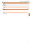
1
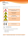
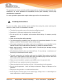
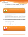
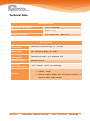
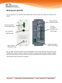
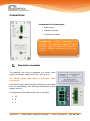
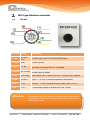
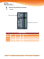
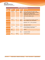
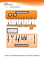
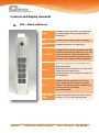
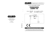
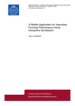
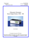
User manual Ultrasonics Generator soniKKs digital K3DR - W Device above without – below with Profibus socket 2015-02-25 soniKKs GmbH - Ultrasonics Technology Doc.nr.: 3000.2302-A page 1 of 24 Table of contents Table of contents ................................................................................................................. 2 Introduction ......................................................................................................................... 3 General information .............................................................................................................. 3 Safety ................................................................................................................................. 4 Conventional use ........................................................................................................ 4 Security instructions.................................................................................................... 5 Device Placement ................................................................................................................. 7 Technical Data ..................................................................................................................... 8 Back panel variants .............................................................................................................. 9 Connections ....................................................................................................................... 10 Electrical connection ................................................................................................. 10 M12-type Interface connector .................................................................................... 11 2.1. Pin-out ................................................................................................... 11 2.2. Example of application............................................................................. 12 2.3. Interface signals description..................................................................... 13 Phoenix-type Interface connector ............................................................................... 14 3.1. Pin-out ................................................................................................... 14 3.2. Example of application............................................................................. 16 Profibus-socket (optional) .......................................................................................... 17 Controls and display elements ............................................................................................. 18 LED – Status indicators ............................................................................................. 18 Controls and connections .......................................................................................... 19 Troubleshooting ................................................................................................................. 20 Maintenance and care ......................................................................................................... 22 Warranty ........................................................................................................................... 22 Declaration of Conformity.................................................................................................... 23 Imprint .............................................................................................................................. 24 2015-02-25 soniKKs GmbH - Ultrasonics Technology Doc.nr.: 3000.2302-A page 2 of 24 Introduction Dear customer, we would like to thank you for buying this product. You have purchased a high-quality product, developed based on the latest technology standards, developed and produced exclusively in Germany. General information The ultrasonic generator “soniKKs digital K3 DR – W” can be used for ultrasonic plastic- and metalwelding applications as well as for other special applications like sieving, atomizing, etc. The main features are: Auto-tuning circuit to tune automatically to the resonant frequency of the connected horn. Fully digital frequency generation. High speed microcontroller to control all functions of the generator. LCD-display with rotary encoder – or touchscreen-operation (except device in Profibusversion). Constant / adjustable amplitude 50 – 100 % Protected against 2015-02-25 o Short circuit o Idle run o Overtemperature o Overload soniKKs GmbH - Ultrasonics Technology Doc.nr.: 3000.2302-A page 3 of 24 Safety Below you can see all the warning and security symbols used in this manual. Symbols in manual: Immediate imminent danger – health and life (bad injuries or death) Attention hot surface. Do not Touch! Possible damage, without danger for people Electrical voltage! Symbols on device: CE Conformity Symbol Conventional use The generator was designed to be used for following applications: Ultrasonic welding of plastic and metal Ultrasonic cutting Ultrasonic sieving 2015-02-25 soniKKs GmbH - Ultrasonics Technology Doc.nr.: 3000.2302-A page 4 of 24 This generator can only be used with soniKKs components (i.e. transducers, sonotrodes and other accessories). We cannot guarantee the compatibility and the good functioning of third party manufacturers’ components. For other applications please obtain explicit written approval from the manufacturer! Security instructions For your own safety, please read this manual carefully before using this product and keep this manual in a place, where it is accessible for all users. The electrical connection may only be done by qualified personnel. Operations of all ultrasonic equipment by trained staff only! Do not use this unit in explosive environments without taking all necessary security measures! Check the unit any time before operating. The electromagnetic compatibility must be conform to international standards. For more details, consult the “Technical data”-section of this manual. All necessary adjustments are either made by the manufacturer or are described in this manual. In case of any trouble with the generator, do contact our technical service. Never open the unit or, in any way tamper with it. This will void your warranty and may cause an electric shock. All maintenance should be done by trained staff only. For any cleaning or maintenance of the device, do disconnect the mains supply. The cable connected to the interface socket must be shielded. Please make sure that this cable is not in close contact to other cables that are conducting high currents. Also avoid close contact of this cable to transformers and relays. Please connect the shield to protective earth (GND) only on the generator side. All I/O signals have a galvanic contact to the generator. Please pay attention at all warnings and hints in this manual and on the generator. Do not use the generator in wet and damp environment. Danger of damage on the generator. Always place the generator on a stable and flat surface. Great attention should be given to the mains supply voltage. Over- or undervoltage can cause malfunctions or destroy the generator! 2015-02-25 soniKKs GmbH - Ultrasonics Technology Doc.nr.: 3000.2302-A page 5 of 24 Correct operations can only be guaranteed if the generator is used along with the recommended ultrasonic transducers. Use only the recommended interface cables. Do not coil up the RF-cable or the line cord. Coiling up these cables can cause overheating of the cables. Do not touch the horn/sonotrode while the generator is active. Caution – could be very hot! ATTENTION! Continuous operation will lead to hot surfaces of the horn and the sonotrode. They can heat up to 100°C! Never point the connected transducer at people. If you work with sonotrodes please wear an adequate ear protection or just operate in an acoustic noise protection box. Avoid all operation of the generator in presence of animals. They have a more extended frequency range of audible sound than people and are thus highly sensitive to ultrasounds. In the following cases, immediately disconnect the unit from mains and call a qualified service technician: If cables or connectors are damaged If the housing is damaged If fluid came into the generator If the unit fell to the ground If the unit shows significant differences from normal operation ATTENTION! 2015-02-25 Only qualified personnel is allowed to do any modifications on the device. soniKKs GmbH - Ultrasonics Technology Doc.nr.: 3000.2302-A page 6 of 24 Device Placement A running generator can heat up noticeably. If the generator cannot dissipate the heat, there is a possibility of an overheat condition. An error message “Overtemperature” will appear if a display is connected and the “OVERTEMP”-LED will light up. See the error description “Overtemperature” for details. If possible, avoid operating the unit at ambient temperatures above 30°C/86°F. Make sure that sufficient cool air can reach the generator for proper cooling. Air conditioning helps in high temperature environment. Always keep the cooling slots on the rear of the generator clear! Do not place anything in front of the cooling slots. Keep the generator away from heat sources to avoid overheating. Also avoid direct sunlight exposure. Place the unit so that no humidity or fluid can come into the generator. Lay the cables in a way that no one can stand on them or stumble over them. Never lift the device or carry it by its cables. ATTENTION! Place the unit in a way that no vapor (water or other) can get into the device. Dusty or chemically contaminated air may cause long-term corrosion of the device Avoid heat sources close to the generator to prevent overheating. 2015-02-25 soniKKs GmbH - Ultrasonics Technology Doc.nr.: 3000.2302-A page 7 of 24 Technical Data Mechanical Data Dimensions (W x H x D) 175 x 70 x 362 mm Weight approx. 2,5 kg Protection category IP 20 IEC 60 529 EN 60 525 Electrical Data Operating frequencies Depending on generator type 20 - 100 kHz Mains supply 210 - 250 VAC (L,N,PE) ; 50 - 60Hz Current consumption Depending on model - up to maximum 10 A Ultrasonic power Maximum 2000 W Operating temperature range - 10°C through + 40°C, not condensing RS232 - socket Options 2015-02-25 Profibus - socket External graphic display with touchscreen-operation or operation with a rotary encoder soniKKs GmbH - Ultrasonics Technology Doc.nr.: 3000.2302-A page 8 of 24 Back panel variants Our K2 generators are available with different back panels which offer different connectors (see below). LEMO connector (transducer plug) Phoenix connector (mains supply plug) Phoenix connectors (Interface and RS232 plugs) M12 connector (Interface plug) Phoenix connector (mains supply plug) BNC connector (transducer plug) NB: the BNC and LEMO sockets are interchangeable, which means that the right panel is also available with a BNC connector. However, the other connectors (power supply sockets included) cannot be interchanged. In other words, you cannot combine the M12 interface connector with the right Phoenix mains connector for instance. 2015-02-25 soniKKs GmbH - Ultrasonics Technology Doc.nr.: 3000.2302-A page 9 of 24 Connections Connections of the back panel: Mains supply Interface connector Transducer connector ATTENTION! When connecting a converter, an additional protective earth connection must be provided. This cable must provide a sufficient cross-section of at least 1,5mm². Electrical connection The generator may only be connected to a proper mains supply. The allowed voltage is 230 Volt / AC / 50-0 Hz. The Mains supply must have a protective earth connection! Care must be taken that the supply connection carries neither over- nor undervoltage – this may cause malfunctions or even damage the unit. Pin assignment of the mains socket (see on the right): 1. PE 2. N 3. L 2015-02-25 soniKKs GmbH - Ultrasonics Technology Doc.nr.: 3000.2302-A page 10 of 24 M12-type Interface connector 2.1. Pin-out Pin/ Color Signal Description 1 / white RF-DA & Error Common relay-root for RF-DA and ERROR relays 2 / brown GND Common ground 3 / green FS- ND Remote input (active low) – link to ground to turn on the generator Optionally also remote with 24 V is available 4 / yellow RF-DA relay Relay output “RF-DA”, closed when ultrasonic voltage is emitted normally open by default 5 / grey Error relay Relay output “Error”, closes upon error - normally open by default 6 / pink A-extern Input 5 – 10 Volt, for external adjustment of amplitude 7 / blue P-out Output 0 – 10 Volt, corresponds to the output power 0-100 % 8 / red +15 V 15 Volt supply voltage for external use (max. 100mA) ATTENTION! 2015-02-25 The specified core colors relate to the cables supplied by the device manufacturer. Cables from third party manufacturers might have a different color coding. soniKKs GmbH - Ultrasonics Technology Doc.nr.: 3000.2302-A page 11 of 24 Example of application 2.2. Generator: 8-pole Interface socket HFDA Relay Error Relay 5 1 6 4 7 3 2 8 6 Error HF-DA Error HFDA A-Ext. 5-10V P-Out 0-10V FSGND Max: 24V 100mA GND +15V OUT Max. 100mA +10V Error RF V Example of external connections 2015-02-25 soniKKs GmbH - Ultrasonics Technology Doc.nr.: 3000.2302-A page 12 of 24 2.3. Interface signals description (1) RF-DA & Error Common input/output root of the internal relays “RF-DA” and “ERROR”. Relay input/output signals have no reference to GND. (2) GND Common reference point for input / output signals (except for the relay outputs). (3) FS- GND To switch the generator on, connect this signal to GND (pin 2). (4) RF- DA relay As soon as ultrasonic voltage is available on the RF-output socket, a relay contact closes, and this pin (4) is linked via the relay to Pin 1 (RF-DA & ERROR). Normally open by default (user-configurable). To use this function, connect, for instance 24V to pin 1 (RFDA & ERROR). This voltage will then appear on this pin 4, as soon as the generator is turned on, and an ultrasonic signal is available on the output socket. (5) Error relay This pin is internally connected to the error relay contact (root of the relay-contact is pin 1). Normally open by default (user-configurable). If there is any malfunction of the generator, this relay contact will be closed. (6) A- extern The generator´s amplitude can be controlled with an external voltage applied to this pin. This function can be enabled on the external display. Applying a vo0ltage between 5 and 10V, the amplitude can be adjusted in a range of 50-100% of the nominal generator amplitude. Any voltage below 5V will clip the amplitude to 50%. (7) P- Out On this pin there is a voltage proportional to the emitted ultrasonic-power in the range of 0-10 volts. This voltage corresponds to the nominal ultrasonic output power. 0V = 0% / 10V = 100%. (8) + 15 V This output provides an auxiliary voltage of +15V for external use. The maximum output current is 100mA (75mA permanent load) and can be used as a supply voltage of the relay root “RF-DA &Error” on pin 1. 2015-02-25 soniKKs GmbH - Ultrasonics Technology Doc.nr.: 3000.2302-A page 13 of 24 Phoenix-type Interface connector Pin-out 3.1. Modbus interface Status and Control I/O Modbus interface Pin Number Signal Direction Level Description 1 RS232-GND Output - Ground reference used for the RS232 bus 2 RS232-TXD Output ±5V Modbus transmitting pin 3 RS232-RXD Input ±5V Modbus receiving pin 2015-02-25 soniKKs GmbH - Ultrasonics Technology Doc.nr.: 3000.2302-A page 14 of 24 Status and Control I/O Pin Number Signal Direction Level Description 1, 9 HF / RF I/O Up to 24V “RF-DA” relay input and output. Relay closed when ultrasonic voltage is emitted. Normally open by default (userconfigurable). Relay also works as control relay in cycle welding mode. 2 REM-24V Input +24V Remote input (active high). Reference is GND. 3, 4 ERROR I/O Up to 24V “Error” relay input and output. Normally open by default (user-configurable). 5 A-5-10V Input 5-10V Input for amplitude control 5V = 50% amplitude / 10V = 100% amplitude. 6 P-0-10V Output 0-10V Output corresponding to the current output power level 0-100%. 7 TEMP Input Option Analog voltage corresponding to the current transducer temperature. 8 +15VOUT Output +15V 15V supply voltage for external use (max. 100mA). 10 REM-GND Input Up to 24V Remote input (active low). Generator ON if connected to GND. 11 GND Output - Common ground. 2015-02-25 soniKKs GmbH - Ultrasonics Technology Doc.nr.: 3000.2302-A page 15 of 24 Example of application 3.2. Generator: 11-pole interface Error Relay 3 HF-DA Relay 4 Error Error 1 9 HF/RF HF/RF 5 6 A-510V 6 7 P-010V TEMP 10 REMGND 11 GND 8 +15V OUT 2 REM24V Max. 100mA Please note: The HF-DA relay connected to pin 1 and 9 can also be configured as a driver relay for a pneumatic cylinder. Pls. refer to the manual section “Cycle mode”. +10V Temp. sensor RF Error V Example of external connections 2015-02-25 soniKKs GmbH - Ultrasonics Technology Doc.nr.: 3000.2302-A page 16 of 24 Profibus-socket (optional) Code – switches to change the Profibus address. Code Hexadecimal Bus-Adress-L Low byte Bus-Adress-H High byte Example: “11” Address decimal 17 “22” Address decimal 34 ATTENTION! The bus address is only checked one time when the generator is connected to the mains supply. ATTENTION! Please connect a ground-cable with sufficient cross-section (minimum 6 mm²) to the ground-socket on the front. 2015-02-25 soniKKs GmbH - Ultrasonics Technology Doc.nr.: 3000.2302-A page 17 of 24 Controls and display elements LED – Status indicators 2015-02-25 Power Indicates that the generator is connected to the mains supply and the mains switch is switched on. Sonic Indicates that ultrasonic power is emitted. Error Indicates that there is a malfunction. <> Nominal Indicates that a monitoring function has been set and the requested condition was not met during the last run. Cleared automatically upon next start. Monitoring functions can be set using a LCD-display (extern/integrated). >temp. When lit, the generator is overheating and cannot be started. When flashing, the generator was shut down during the last process due to overtemperature. If you start sonic again the LED disappears. Mode Indicates that the generator s set to stop after a predetermined condition has been reached. The setting of these conditions can be done with the LCD-display (extern/integrated). LED – Power gauge Shows the effective ultrasonic power output in steps of 10 % of the nominal power. soniKKs GmbH - Ultrasonics Technology Doc.nr.: 3000.2302-A page 18 of 24 Controls and connections Test – Button By pressing this button, you can switch on the generator for testing purposes. The button behavior can be configured using the LCDdisplay (extern/integrated). Userport Possibility to connect an external display and also an interface can be connected with a special adapter cable. 2015-02-25 soniKKs GmbH - Ultrasonics Technology Doc.nr.: 3000.2302-A page 19 of 24 Troubleshooting The “Error” LED comes up right after the generator is started with the testbutton or a remote control signal: Possible reasons Malfunction of the ultrasonic converter Malfunction of the cable to the transducer (short circuit) How to fix the problem 1. Disconnect the cable to the transducer 2. Switch on the generator with the test button Then what? a. The error still comes up: generator faulty b. The error does not come up again: transducer or cable faulty The “Error”-LED comes up with some delay after the generator is started with the test-button or a remote control signal: Possible reasons There is no ultrasonic converter connected The tool has a malfunction The ultrasonic converter is broken Malfunction of the connection cable or plug How to fix the problem 1. Check the transducer, converter and sonotrode; exchange them if necessary 2. Check cabling and connectors, exchange them if necessary 2015-02-25 soniKKs GmbH - Ultrasonics Technology Doc.nr.: 3000.2302-A page 20 of 24 “Overtemp”-LED lights up or flashes: If the generator gets overheated during sonification, the “Overtemp.” – LED will light up and the generator switches off automatically. When cooling-down below the trip-point, the generator restarts automatically. The “Overtemp.” – LED will flash to signalize this error until the generator is switched off with the test-button or the remote-control. Possible reasons The cooling slots are obstructed Device is placed too close to another heat source Malfunction in the converter Malfunction of the fan How to fix the problem 1. Check the fan! 2. Check the cooling slots on the backside of the generator. 3. Check device placement, pay attention at the placement advice! The generator starts and stops on its own: How to fix the problem 1. Set the “Timer” value to zero 2. Verify that the “MODE‟-LED is off 3. Restart the generator 2015-02-25 soniKKs GmbH - Ultrasonics Technology Doc.nr.: 3000.2302-A page 21 of 24 Maintenance and care There is no need for special maintenance! Please remove any dust and dirt with a damp woven fabric. Do not use any chemicals to clean the generator. Keep the cooling slots clear at all times. Warranty The period and extent of the warranty is part of the commercial terms and conditions. Special agreements are part of the confirmation of the order. The warranty does not cover any malfunctions, injuries and damages that result from such use or improper operation in use. Warranty exclusion applies in the following cases: Damage due to wrong handling or tampering Damage due to wrong application Damage due to shock, dirt or moisture Damage due to operation by nonqualified staff Damage due to nonobservance of safety regulations or accident prevention regulations Damage due to modifications to the operating manual 2015-02-25 soniKKs GmbH - Ultrasonics Technology Doc.nr.: 3000.2302-A page 22 of 24 Declaration of Conformity We: soniKKs Ultrasonics Technology GmbH, declare in sole responsibility that the product: Type: Ultrasonic generator “soniKKs digital K3 DR - W xxxx” (where “xxxx” indicates the power ratings) Corresponds to the following EEC directives: EN 50081-1 EN 50082-2 EN 55022 EN 55014 EN 6055 EN 61000 The requirements of the low voltage directive are observed. ATTENTION: The device is not designed to be connected to the public utility (AC) power line! Unauthorized modification of the device makes this declaration void. Dobel 01.11.2008 Klaus Kern Managing Director 2015-02-25 soniKKs GmbH - Ultrasonics Technology Doc.nr.: 3000.2302-A page 23 of 24 Imprint Purpose and use The operating instructions explain the construction and operation of the ultrasonic generator “soniKKs K3 DR – W” in connection with standard accessories for use in laboratories and the industry. Please read especially the safety instructions carefully and observe them all time. The operating instructions should always be at hand, to help you to solve any questions and problems that may arise. All rights reserved The manual has been prepared with all due care, nevertheless faults and omissions cannot be fully precluded. soniKKs GmbH reserves the right to make changes to the technical data and specifications during the curse of further development of the product. Without given prior notice. Address Editing soniKKs ® Ultrasonics Technology GmbH Neuenbürgerstraße 72 75335 Dobel Germany first edition: second edition: Phone: Fax: Mail: August 2012 January 2015 + 49 (0) 7083 – 92 48 360 + 49 (0) 7083 – 92 48 370 [email protected] www.sonikks.de www.sonikks.com 2015-02-25 soniKKs GmbH - Ultrasonics Technology Doc.nr.: 3000.2302-A page 24 of 24