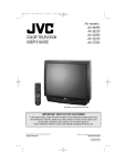
1
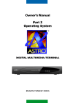
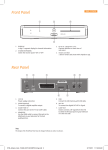
Owner’s Manual
Part 1
TM
DIGITAL MULTIMEDIA TERMINAL
MANUFACTURED BY NOKIA
1
2
DIGITAL MULTIMEDIA TERMINAL 8750 S
Contents
GENERAL OPERATION OF THE DIGITAL
MULTIMEDIA TERMINAL
4
FOR YOUR SAFETY
4
REMOTE CONTROL
5
REAR PANEL
6
FRONT PANEL
6
ABOUT THE SMART CARD
7
Inserting your ASTRO Smart Card
INSTALLATION OF THE DMT
7
8
Preparing the Remote Control
8
Connecting the DMT to the Satellite Dish
8
Connecting the DMT
9
Connecting the DMT to a TV
9
Connecting the DMT to a TV and VCR
9
If your VCR/ TV has S-VHS sockets
10
Connecting a Hi Fi System
10
Connecting to the telephone wall socket
10
Tuning Procedure when RF cables are used
11
GLOSSARY OF TERMS
12
PROBLEM SOLVING
13
TECHNICAL SPECIFICATIONS
14
ASTRO/Nokia Multimedia Terminals operates a policy of continuous
development. Therefore, we reserve the right to make changes and
improvements to any of the products described in this manual.
ASTRO is a trademark of MEASAT Broadcast Network Systems Sdn.
Bhd (240064-A)
NOKIA is a registered trademark of Nokia Corporation.
Copyright © 1999. Nokia Multimedia Terminals.
All rights reserved.
3
GENERAL OPERATION OF THE DIGITAL
MULTIMEDIA TERMINAL
The Digital Multimedia Terminal is refered to as ”DMT”.
In the applications user manual the everyday operation of your DMT is
based on a series of user friendly on-screen displays and menus (please
refer to applications user manual).
These menus will help you get the most from your DMT, guiding you through
installation, channel selection, viewing and many other functions.
All functions can be carried out using the buttons on the remote control, and
some of the functions can also be carried out using the buttons on the front
panel.
The DMT is easy to use, always at your command and adaptable for future
functionality enhancements.
Should you experience any difficulties with the operation of your DMT,
please consult the relevant section of this manual, including the Problem
Solving, or alternatively call ASTRO Customer Service.
FOR YOUR SAFETY
• Allow clear space around the DMT for sufficient
ventilation.
• Do not cover the DMT or place it on a unit that
emits heat.
• Use a soft cloth to clean the casing.
• Never allow liquids, spray or other materials to come
into contact with the DMT.
• Never touch the DMT with wet hands as it may
cause electrical shock
• Do not connect or modify cables when the DMT is
plugged in.
• Do not remove the cover.
• Do not allow the unit to be exposed to hot, cold or
humid conditions.
• Service should only be carried out at an
Authorised Service Centre.
• Please note that the only way to isolate the DMT
completely from the mains supply is to unplug the
mains lead!
• For best protection of your DMT it is strongly advised that a surge protection device be installed (not
included in standard accessory package).
• The EMC Directive 89/336/EEC is applied to this
product.
4
REMOTE CONTROL
This section describes how to operate the DMT using the buttons on the remote control.
To switch the DMT in and out of standby mode.
For future messaging functions.
To turn the sound off/on (mute).
- + To adjust the volume of digital programmes. The DMT maximum
level is controlled by the TV’s present volume setting.
0-9
To select/change channel and to select individual menu options.
0 FAV
Setting of favourite channel list.
I-II
Audio language selection.
Subtitle language selection.
MENU
To display or exit from the ”Main Menu” screen.
GUIDE
To obtain a list of programme schedules for the available channels.
INFO
To display short and extended information (if transmitted) on programme schedules for available channels.
P+ P-
To change channels up and down.
To page up and down.
▲ ▼
To move cursor up and down.
To move cursor left and right.
OK
To confirm choices and selection of a highlighted item.
RGYB
Reserved for future functions.
Some functions can be operated with the front panel buttons of the
DMT. The buttons are identified in the same way as those on your
remote.
For inserting the batteries in the remote control, see page 8.
5
REAR PANEL
Mains lead
95-260 V AC,
50/60 Hz
S-VHS
for connection to
the S-VHS socket
on the TV
(cable is optional)
VIDEO
video signal
for the video
input on the
TV or VCR
AUDIO L R
for the audio input
on the TV, VCR or
HiFi system
TELEPHONE
for modem
connection via
the splitter to
the telephone
wall socket
SERIAL
for PC
connection
(future
function)
TV/VCR
for an RFcable to the
aerial input
of the TV or
VCR
PARALLEL
for PC
connection
(future
function)
ANTENNA *
Satellite dish
input (Fconnector)
TV AERIAL
for standard
TV antenna
* LNB cable also feeds the LNB with a
supply voltage of 13/18 V (V/H polarisation) and a 22 kHz signal (bandswitch).
Max LNB current 350 mA.
FRONT PANEL
Please flip open the front panel
cover to access the front
control panel.
Smart Card 1
for the ASTRO
Smart Card
6
MENU
to select
Main Menu
Smart Card 2
for a 2nd Smart
Card
(for future use)
GUIDE
to access
programme
schedules
to put the
DMT in and
out of
standby
mode
to move cursor
up and down
Display
indicates remote control
commands and displays channel
numbers when active;
displays current time when in
standby
OK
to confirm choices and
selection of a
highlighted item
to move cursor
left and right
ABOUT THE SMART CARD
To be able to receive scrambled digital satellite channels you will need a Smart
Card from ASTRO.
Only Free-to-Air channels are available without the Smart Card.
Note: The Smart Card is delivered together with the DMT in a separate envelope.
After inserting the Smart Card, leave it in the slot permanently.
New and updated information may be downloaded onto the Smart Card from
time to time.
Inserting your Smart Card
• Insert your ASTRO Smart Card fully into Smart Card slot 1 behind the lid
of the DMT front panel.
The gold chip should face downwards and inwards.
• Smart Card slot 2 (reserved for future use).
Smart Card 1
Smart Card 2
Note! The gold
chip must be on
the underside
and inwards of
the Smart Card
7
INSTALLATION OF THE DMT
The box for your DMT should contain the following items:
• the DMT
• a remote control with 2 AAA batteries
• an RCA audio/video cable (2,0 metres)
• an aerial/RF cable (double screened 2 metres)
Telephone
modem cable
and splitter
• a telephone modem cable (10 metres)
• a telephone connector splitter
RF cable
Audio/Video
cable
• manuals
• a warranty card
• an ASTRO Smart Card (in envelope)
Manuals
Warranty
Card
Smart Card
Remote
control &
batteries
Preparing the Remote Control
• Remove the cover on the battery compartment at the bottom of the remote
control.
• Insert the 2 AAA (1,5 V) batteries, as shown in the diagram, taking care to
observe the + and - markings indicated inside.
+-
-+
Connecting the DMT to the Satellite Dish
15 mm
If you need to fit the F-connectors onto the cable
8 mm
• Prepare each end of the cable as shown in the diagram. You will need to
fold back the outer braid (as shown).
• Slide the F-connector onto the cable, then turn it clockwise until it grips the
braid.
• Ensure that 3 mm of the core is protruding from the end of the connector.
F-connector
3 mm
Connecting the satellite cable
• Connect the satellite cable, with F-connectors fitted, from the satellite dish
to the input socket marked ”ANTENNA”on the rear panel of the DMT.
8
Connecting the DMT
There are different types of TV/VCRs and other equipment that you can connect to the DMT.
In this manual you will see some of the most common ways to connect your
equipment.
If you use RF cable you will have to tune your TV and VCR to the DMT output channel (see page 11).
If you have problems with your connections and need help, contact ASTRO
Customer Service.
Connecting the DMT to a TV
• Connect the Audio/Video cable between the TV and the AUDIO/
VIDEO L R sockets on the DMT.
• Connect an RF cable from the TV AERIAL input socket on the
TV to the TV/VCR output of the DMT.
• Connect the TV aerial directly to the TV AERIAL input socket on
the DMT.
RF
OUT
IN
Video
DMT
Audio
Connecting the DMT to a TV and VCR
Refer to your VCR’s manual for full instructions.
If your TV has a Audio/Video socket, but your VCR does not
RF
• Connect the Audio/Video cable between the TV and the VIDEO/
AUDIO L R sockets on the DMT.
VCR
• Connect an RF cable from the RF output on the
VCR to the TV aerial input socket on the TV.
• Connect an RF cable from the RF input socket on the
VCR to the TV/VCR output socket on the DMT.
• Connect the TV aerial directly to the TV AERIAL input socket on
the DMT.
RF
OUT
RF
IN
DMT
Video
Audio
If your VCR has a Audio/Video socket, but your TV does not
RF
• Connect the Audio/Video cable between the VCR and the
VIDEO/AUDIO L R sockets on the DMT.
• Connect an RF cable from the RF output socket on the
VCR to the TV aerial input socket on the TV.
• Connect an RF cable from the RF input socket on the
VCR to the TV/VCR output socket on the DMT.
• Connect the TV aerial directly to the TV AERIAL input socket
on the DMT.
OUT
RF
IN
VCR
Video
RF
Audio
DMT
9
If your TV has a S-VHS socket (S-VHS cable is not included)
• Connect a S-VHS cable from the S-VHS socket on the DMT to the
S-VHS input socket on your TV.
• Connect an RF cable from the RF output socket on the
VCR to the TV aerial input socket on the TV.
OUT
• Connect the Audio cable between the AUDIO L R sockets on the DMT
and the input sockets on the TV.
• Connect an RF cable from the TV/VCR output socket on the DMT to
the RF input socket on the VCR.
RF
OUT
• Connect the TV aerial directly to the TV AERIAL input socket on the
DMT .
IN
VCR
RF
IN
Audio
S-VHS
DMT
Connecting a Hi Fi System
• Connect the audio L/R cable from the DMT to the LINE, AUX input sockets on your Hi Fi system.
DMT
Connecting to the Telephone Wall Socket
In the future you will be offered interactive and Pay-Per-View services from
ASTRO. You may then need to connect the DMT to a telephone line.
• To connect the modem cable, plug the cable from the DMT TELEPHONE
socket into the enclosed splitter.
• Connect the telephone cable to the splitter and the splitter to the wall socket.
• For best protection of your DMT it is strongly advised that a surge protection device is installed. (Surge protector not included).
DMT
10
Tuning Procedure when RF Cables are used
This procedure is necessary only if your DMT is connected to the TV with
an RF cable.
To tune your TV to the RF signal you might also need your TV manual in addition to this manual. The steps below explain what to do if you have been unable to use audio/video cables in your connection.
• Plug in your TV and DMT.
• Switch on the TV.
• Switch on the DMT.
Tuning your TV to the DMT
• Select a channel number on the TV set that is not currently used for other
TV channels.
• Follow the instructions in your TV manual to tune the TV channel selector
to UHF channel 39 (this is the DMT’s factory preset UHF channel).
• If you are unable to receive the DMT signal, please refer to the applications
user manual for proper instructions.
• Follow the instructions in your TV manual to store this UHF channel as the
channel used by your DMT. You will have to select it when you want to watch
digital TV/Radio channels.
Note: If you have a VCR connected with an RF cable it must be tuned to a
different channel compared to the DMT output channel.
11
GLOSSARY OF TERMS
Access
Authorisation to use the coding system to purchase / order
TV programmes and Services.
MHz
The prefix mega means million, and Hertz means cycles per
second.
Audio system
With digital satellite reception, the sound is transmitted in
packages and is selected either in a special audio mode
or pre-selected by using the installation set-up. This makes
it possible to select between several different languages in
a film. The number of choices is dependent on what is available in the signal.
MPEG
Moving Picture Experts Group. Body established by the International Standards Organisation to provide the basis for
a picture coding and compression system.
DMT (Digital Multimedia Terminal)
A unit that converts the digital satellite signals into audio
and video signals.
DVB
The Digital Video Broadcast group was created to establish a technical framework for the introduction of digital
video broadcasting systems.
FEC
Forward Error Correction. Correction of faulty bits in the received signal.
GHz
The prefix giga means billion, and Hertz means cycles per
second. Signals in the GHz range are often called microwaves.
GUIDE
Programme Schedules. An application that enables viewers to navigate easily among the large number of channels
provided by digital technology, in order to select the service they desire.
ODU
”Out Door Unit”. Includes Dish, LNB and Accessories
Polarization
Polarization allows several programmes to fit into the same
frequency band. The signals from a satellite are transmitted
either with linear (vertical or horizontal) polarization or circular (right or left) polarization.
RF
Radio frequency (known as HF in some countries).
RS 232
A serial communication standard data port.
Satellite dish
A dish-shaped antenna (reflector) to receive signals from a
satellite. The dish focuses the signals into the LNB.
Scrambled satellite TV programme
Satellite TV programmes may be transmitted in scrambled
form. A Smartcard will be needed to view such programmes.
Service provider
Is a company that collects a number of program/services and
distributes them to customers.
LNB (low-noise block converter) or LNBF
Symbol rate
Size of the digital package transmission.
An electronic unit mounted on the satellite dish. It receives
the signals reflected by the dish and converts them to signals that can be used by the Mediamaster.
S-VHS
A means to transport a high quality video signal (also known
as S-VIDEO).
VCR
Video Cassette Recorder.
12
PROBLEM SOLVING
Problem
Possible causes
What to do
The display on the front panel does not
light up/is not lit.
Mains cable is not connected.
Check that the mains cable is plugged in to the
power socket.
No sound or picture, but the front panel
shows the time or - - : - -.
The DMT is in standby. mode
Press the standby button or any number button
to bring the DMT out of standby mode.
No sound or picture.
The satellite dish is not pointing
at the satellite.
No signal or weak signal.
Adjust the dish. Check the signal level indicator
in one of the channel search submenus.
Check the cable connections, LNB and other
equipment connected between the LNB and
the receiver, or adjust the dish.
Severe weather conditions and heavy cloud
cover may also produce this effect.
Replace the LNB.
The LNB is faulty.
Bad picture/blocking error.
The satellite dish is not pointing
at the satellite.
The LNB is faulty.
Adjust the dish.
Change the LNB.
There is no menu on the screen after you The system is connected by audio/video
switched on the DMT for the first time.
cables and the TV is not in AV/Video
mode.
The system is connected by RF cables
and the TV is not set to the channel
tuned for digital satellite TV.
If the system is connected by audio/video
cables, switch the TV to the appropriate AV
input.
If the system is connected by RF cables, switch
the TV to the channel for digital satellite TV. If
you have not tuned in the TV you may do this
first. Please look in the TV manual for instructions.
There is interference on your digital The system is connected by RF cables
satellite channels, by a terrestrial channel and the output channel of the DMT
or RF signal.
interferes with a terrestrial channel or RF
signal.
Change the DMT output channel to a more
suitable channel between 21-69. Or connect
the system by audio/video cables.
You made a video recording of a digital The DMT was not left on the appropriate
satellite channel and whole or parts of the channel.
programme was not recorded.
The system is connected by audio/video
cables and the VCR is not in AV/Video
mode.
The system is connected by RF cables
and the VCR is not set to the channel
tuned for digital satellite TV.
If you make a recording of digital satellite TV
your DMT has to be left on the channel you
want to record.
If the system is connected by audio/video
cables, switch the VCR to appropriate AV/
VIDEO input.
If the system is connected by RF cables, switch
the VCR to the channel for digital satellite TV. If
you have not tuned in the VCR you may do this
first. Please look in the VCR manual for
instructions.
The remote control is not working.
Battery low.
Remote control is incorrectly
aimed.
Change the batteries.
Aim the remote control at the DMT.
Check that nothing blocks the front panel.
Check if a dot (.) is flashing on the front panel
display when you press a button.
If not replace both batteries.
Smart Card error messages.
The DMT can’t recognise or detect your
Smart Card.
Check that you are using the proper Smart
Card. Check that the Smart Card has been
correctly inserted. If the problem persists, you
may have a problem with the card.
Contact ASTRO Customer Service.
You have forgotten your secret PIN code.
Contact ASTRO Customer Service. They will
help you set it up again.
What to do if you can’t solve the problem
If you have tried all of the actions suggested above, without solving the problem,
please contact ASTRO Customer Service.
13
TECHNICAL SPECIFICATIONS
Transmission Standards
DVB, MPEG 2
LNB / Tuner input
Connector
1x female F-type
RF input frequency 950-2150 MHz
RF input power level -20 to -70 dBm
Supply voltage
13,5 /18,5 V ±5%
Max. current
350 mA, overload protected
Control voltage
22 kHz, 0,65 Vpp
RF impedance
75 Ω
RF modulator
Input/output connector IEC female / IEC male
Modulator frequency
470 to 862 MHz
Output level
70 ± 5dBV
Output channel
21-69
Preset channel
39
Output signal
PAL G
Sound carrier
5,5 MHz
Design
Loop through output
Video interface
Connector
1 x RCA
Composite video output
Video output
1 Vpp (±1 dB)/ 75 Ω
Video bandwidth
0..5 MHz
AUDIO R L
Connector
Output
2 x RCA (R+L)
0,5 Vrms ± 0,5 dB/ RL 10 kΩ
S-VHS
Connector
Y
C
Impedance
1 x Mini-DIN
Luminance signal 1 Vpp
Chrominance
75 Ω
SERIAL (RS 232) Serial data
Connector
9-pin D-sub male
Signals
Pin 1 DCD
2 RXD
3 TXD
4 DTR
5 GND
6 DSR
7 RTS
8 CTS
9 RI
14
RS232, max. 115,2 kbit/s
(Data carrier detect) not connected
(Receive data)
(Transmit data)
(Data terminal ready) Set to high
(Signal ground)
(Data set ready) not connected
(Ready to send)
(Clear to send)
(Ring indicator) not connected
MODEM Return channel, Telephone line
Connector
Modular jack 6-pin RJ-11
Protocol
V22 bis 2400 baud
PARALLEL High speed data port
Connector
IEEE 1284, 25-pin D-sub female
Signals
Compliant to the standard IEEE 1284 - 1994
Smartcard Interface:
Interface for two cards according to ISO 7816
Supports embedded descrambler Conditional Access system.
Front panel
4x7 segment numeric LED display,
Buttons: ,
,
, MENU, GUIDE, OK
General data
Article code:
The model code, variant and serial number,
are located on a label on the underside of the housing.
Supply voltage
Power consumption max
Mains cable length
Operating temperature
Storage temperature
Humidity
Operating distance for
remote control
Dimensions (w x d x h)
Weight
95 - 260 V AC, 50 - 60 Hz
24 W at 350 mA LNB load
2 metres
+5° C to +45° C
- 40° C to +65° C
25 to 90 % rel humidity
max 10 metres
380 x 240 x 65 mm
1,8 kg approx
NOKIA is a registered trademark of Nokia Corporation
ASTRO is a trademark of MEASAT Broadcast Network
Systems Sdn. Bhd (240064-A)
66 76940-10
www.nokia.com
www.astro.com.my
© 9927
15