1
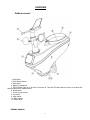
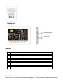
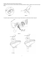
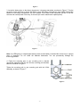
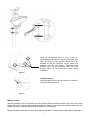
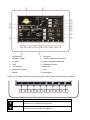
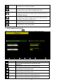
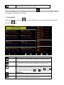
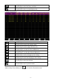
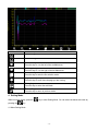
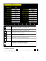
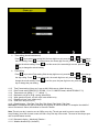
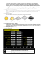
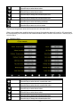
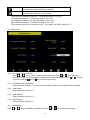
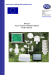
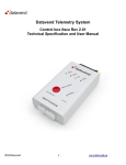
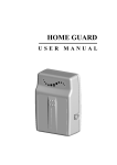
PROFESSIONAL WIRELESS WEATHER STATION Operation Manual -1- OVERVIEW Outdoor sensor: 1. Wind Vane 2. Wind Speed Sensor 3. Solar panel 4. Battery compartment 5. LED Indicator: light on for 4s if the unit power up. Then the LED will flash once every 16 seconds (the sensor transmission update period). 6. Reset button 7. Thermo-hygro sensor 8. UV sensor 9. Light sensor 10. Rain collector 11. Bubble level Indoor sensor -2- Display unit memory card slot Power jack reset Contents The weather station consists of the following parts. QTY 1 1 1 1 1 1 2 4 4 1 Item Display Console Outdoor sensor(Thermo-hygrometer / Rain Gauge / Wind Speed Sensor /Transmitter) Wind Vane Indoor sensor 5V DC adaptor Pole Pole mounting U-bolt Pole mounting clamps Pole mounting nuts User manual Introduction Thank you for your purchase this professional weather station. The outdoor sensor is solar powered and sends -3- data to the console via a low-power radio. This manual will guide you step-by-step through setting up your device. Use this manual to become familiar with your professional weather station, and save it for future reference. Feature Display illumination Weather data calibration Time Date Wireless outdoor sensor Indoor temperature Indoor humidity Air pressure Outdoor temperature Outdoor humidity Display ℃ or ℉ Wind speed Wind direction UV index Solar power Weather forecast Calendar Wind chill Dew point Max/min memory Alarm on exceeding values 12/24 hour display Time alarm Wall mount Table stand Range 100 meter Installation Before placing and installing all components of the weather station at there final destination, please set up the weather station with all parts being nearby for testing the correct function. Outdoor sensor 1. Attach the wind vane -4- Push the wind vane into the shaft. as shown in figure 1. Tighten the set screw with the Allen Wrench (included) as shown in figure 2. Make sure the wind vane spin freely. Figure 1 Figure 2 2. Insert the pole into the base, as shown in figure 3. Spin the lid onto the base as shown in figure 4. Togue and groove joint Figure 3 -5- Figure 4 3. Locate the battery door on the thermo-hygrometer / rain gauge transmitter, as shown in Figure 5. Turn the set screw counter clockwise to loosen the screw to open the battery compartment. Insert 3XAA rechargeable batteries in the battery compartment The LED indicator on the back of the transmitter will turn on for four seconds and normally flash once every 16 seconds (the sensor transmission update period). Figure 5 Note: If no LED light up or is lighted permanently, make sure the battery is inserted the correct way or a proper reset is happened. Do not install the batteries backwards. You can permanently damage the thermo-hygrometer. 4. Fasten the mounting pole to your mounting pole or bracket (purchased separately) with the two U-bolts, mounting pole brackets and nuts, as shown in Figure 6. Tighten the mounting pole to your mounting pole with the U-Bolt assembly, as shown in Figure 7.. Figure 6 -6- there are four alphabet letter of “N”,”E”,”S”and “W” representing for the direction of North, East, South and West, as Figure 8. Wind direction sensor has to be adjusted so that the directions on the sensor are matching with your real location. Permanent wind direction error will be introduced when the wind direction sensor is not positioned correctly during installation. Figure 8 Level the sensors Use the bubble level on the rain sensor as a guide to verify that sensors are level. Figure 9 indoor sensor Remove the battery door on the back of the sensor with a Philips screwdriver (there is only one screw, at the bottom of the unit). Insert two AAA batteries as shown in Figure 10 (we recommend lithium batteries for cold weather climates, but alkaline batteries are sufficient for most climates). Replace the battery door and set screw. Note that the temperature, humidity and pressure will be displayed on -7- the LCD display. Looking at the back of the unit from left to right, the polarity is (-) (+) for the top battery and (+) (-) for the bottom battery. Figure 10 Initial Display Console Set Up Connect the power adapter to power up the display console. The display console starts to register the transmitter and receiver the weather data from transmitter. The interface as below: Program Mode 1. Normal display Mode -8- 1. Wind direction 8. Dew point 2. Weather Forecast 9. Outdoor Temperature &Humidity 3. UV index 10. Indoor Temperature &Humidity 4. Light 11. Low battery indicator 5. Time and date 12. Wind chill 6. Barometric Pressure 13. Gust 7. Rainfall 14. Wind speed Each icon in the display matches a black keys on plastic case. Please press the keys for operation. Icon Description Brightness control key Press this key to enhance the brightness Brightness control key Press this key to decrease the brightness -9- Backlight on/off key Press this key to on/off the backlight Auto backlight control key Press this key to enter the auto backlight setup mode Pressure display key Press this key to choose the display between Absolute pressure and Relative pressure. Rain key Press this key to Shift the display between Rain Rate, Rain Day, Rain Week, Rain Month, and Rain Year. History key Press this key to enter History Mode Setting key Press this key to enter Setting Mode 2. Auto backlight setup mode While in normal display, press the Icon key to enter Auto backlight setup Mode. Description Select key Press this key to select the unit or scrolls the value Select key Press this key to select the unit or scrolls the value. Left key Press this key to select the set value. Right key Press this key to select the set value. Up arrow key Press this key to change the activated option field Down arrow key Press this key to change the activated option field - 10 - Return key Press this key to return to previous mode If the auto backlight turn-on time has been set, you can press key to turn off the backlight within the turn on time. Backlight will turn on again automatically at next turn on time. You can press any key to turn on the backlight for 60s within the turn off time 3. History Mode While in normal display, press the pressing the key to enter History Mode. You can select the below sub-mode by key. 3.1 MAX/MIN Mode Icon Description Selection key Press this key to select the weather MAX/MIN record which need to clear Selection key Press this key to select the weather MAX/MIN record which need to clear Enter key While select the weather MAX/MIN record, press this key to popup Message Box”Are you sure to clear the Max/Min?”Press key or key to select YES or NO. Press the key or key to confirm the selection. Up arrow key Press this key to change the activated option field Down arrow key Press this key to change the activated option field - 11 - History key Press this key to select the History sub-Mode Return key Press this key to return to normal display mode 3.2 History Record Mode Icon Description File Select key Press this key to enter the file selection mode Page Select key Press this key to enter the page selection mode. Scroll left key Press this key to view the left of the scrollable area. Scroll right key Press this key to view the right of the scrollable area. Page up key Press this key to scroll up the page you are viewing Page down key Press this key to scroll down the page you are viewing History key Press this key to select the sub-Mode Return key Press this key to return to previous mode While in History Record Mode, press key to enter the file selection mode: - 12 - Press or key to select the history file of annual data. Press key to exit and open the selected file. Press While in History Record Mode, press the key to delete the selected file. Press key to return to History record Mode. key to enter the page selection mode: Press or to select a digit in a number, press key or key to change the number. Press to change the activated option field and press key or key to confirm. 3.3 History graph mode - 13 - or Icon Description Zoom In key Zoom Out key Scroll left key Press this key to view the left of the scrollable area. Scroll right key Press this key to view the right of the scrollable area. Select file key Press this key to enter the file selection mode Page down key Press this key to scroll down the page you are viewing History key Press this key to select the sub-Mode Return key Press this key to return to previous mode 4. Setting Mode While in normal display, press the pressing the key to enter Setting Mode. You can select the below sub-mode by key 4.1 Menu Setting Mode - 14 - Icon Description Select key Press this key to select the unit or scrolls the value Select key Press this key to select the unit or scrolls the value. Left key Press this key to select the set value. Right key Press this key to select the set value. Up arrow key Press this key to change the activated option field Down arrow key Press this key to change the activated option field Set key Press this key to select the Setting sub-Mode Return key Press this key to return to previous mode 4.1.1. Date and Time setting While in Menu Setting Mode, press enter Date and Time Setup mode: key to select Date and Time Setup field, press - 15 - or key to 1) Time setting (hour/minute/second) Press key to select time setting field, the hour digit turn red, press the the hour setting. Press or to set the minute, the minute digit turn red, press the change the minute setting. Press key to change or key to to set the second, the second digit turn red, press the or key to change the second setting 2) Date setting Press key to select Date setting field, the day digit turn red, press the the day setting. Press or to set the month, the month digit turn red, press the change the month setting. Press key to change the year setting key to change or to set the year, the year digit turn red, press the key to or 4.1.2 Time Format setting (H:mm:ss / h:mm:ss AM / AM h:mm:ss, default H:mm:ss) 4.1.3 Date Format setting (MM-DD-YY, DD-MM –YY or YY- MM-DD format, default DD-MM-YYYY) 4.1.4 Temperature unit setting (℃ / ℉, default ℃) 4.1.5 Barometric unit (hPa / inHg / mmhg, default hPa) 4.1.6 Wind speed unit (km/h, m/s, bft, mph, knots default: m/s) 4.1.7 Rainfall unit (mm, inch, default: mm) 4.1.8 Solar Rad. unit (lux,fc,w/㎡) 4.1.9 Rainfall display(Rain Rate, Rain Day, Rain Week, Rain Month, Rain Year) Rain Rate: it forecast the rain per hour base on the recently 10 minute’s rainfall. For example: the rainfall of recent 10 minutes is 12mm, the rain/hour is 12mm*6=72mm/h. Note: The rain per day is reset to zero at 0:00hr every day. The rain per week is reset to zero at 0:00hr every Sunday, per month is reset to zero at 0:00hr every first day of the month. The reset of the rain per year refer to rainfall season section 4.1.10 Barometric display(Absolutely, Relative) 4.1.11 Weather threshold (2-4, default 3) - 16 - It’s pressure sensitivity setting for weather forecasting. When the pressure rises over weather threshold in past 12 hours the weather upgrades (like from partly cloudy to sunny). When the pressure drops over weather threshold in past 12 hours the weather degrades (like from cloudy to raining). For areas that experience frequent changes in air pressure requires a higher level setting compared to an area where the air pressure is stagnant. For example if 4 is selected, then there must be a fall or rise in air pressure of at least 4hPa needed to change the weather forecast icons. 4.1.12 Storm threshold (3-9, default 4) Similar to the general pressure sensitivity setting it is possible to adjust the storm threshold sensitivity form 3-9 (default 4). When there is a fall over storm threshold within 3 hours, the storm icon will appear. 4.1.13 Current weather The five weather icons are Sunny, Partly Cloudy, Cloudy, Rainy and Storm. Sunny Partly Cloudy Cloudy Rainy Storm 4.1.14 Rainfall season (default: January) Rainfall season influence the annual rainfall maximum, minimum and total value. When one month was selected, the annual rainfall and annual max/min rainfall were zero clearing at 0:00 of the first day of the selected month, 4.1.15 Storing Interval (1-240minutes) 4.2 Alarm Setting Mode Icon Description Select key Press this key to select the unit or scrolls the value Select key Press this key to select the unit or scrolls the value. - 17 - Left key Press this key to select the set value. Right key Press this key to select the set value. Up arrow key Press this key to change the activated option field Down arrow key Press this key to change the activated option field Set key Press this key to select the Setting sub-Mode Return key Press this key to return to previous mode The first row is high alarm value and the second row is low alarm value. When a set weather alarm condition has been triggered, that particular alarm will sound for 120 second and the corresponding icon will flash until the weather condition doesn’t meet the user set level. Press any key to mute the alarm. 4.3 Calibration Mode Icon Description Select key Press this key to select the unit or scrolls the value Select key Press this key to select the unit or scrolls the value. Left key Press this key to select the set value. Right key Press this key to select the set value. Up arrow key Press this key to change the activated option field Down arrow key Press this key to change the activated option field - 18 - Set key Press this key to select the Setting sub-Mode Return key Press this key to return to previous mode Solar Rad. Gain calibration (default is 1.0, adjustment range 0.75 to 1.25) UV calibration (default is 1.0, adjustment range 0.75 to 1.25) Wind Calibration (default is 1.0, adjustment range 0.75 to 1.25) Rain calibration (default is 1.0, adjustment range 0.75 to 1.25) The conversion factor for Lux converter to w/m 2. (The range is 100-1000, default 126.7.) 4.4 Factory reset 4.4.2 Re-register indoor transmitter Press or key to select re-register indoor transmitter. Press or key to popup the Message Box ”Are you sure you want to register the new inddor transmitter?” Press or to select Yes or No. Press the key or key to confirm the selection. 4.4.3 Re-register outdoor transmitter Please reference section 4.4.1. Procedures and settings are similar to re-register indoor transmitter 4.4.4 Clear History Please reference section 4.4.1. 4.4.5 Clear Max/Min Please reference section 4.4.1. 4.4.6 Reset Factory Please reference section 4.4.1 4.4.7 Backup data Press or key to select Backup data field, press the - 19 - or key to enter backup mode: Press or key to select the history year file. Press key or key to confirm the selection. Press or to change the activated option field. Press key to start backup, press key again to stop the backup. Please insert TF card before start backup. The data save as excel format as default setting. TF(MicroSD) cards can be placed into a USB adaptor and then insert to the USB port in PC. Within a second or two the SD card with USB adaptor was detected and showed up as a removable drive on PC. Double click the removable drive icon to check the weather parameter - 20 - Accessing the contents of the card. 4.4.8 4.4.9 Language (English, Chinese, Danish, Dutch, French, German, Italian, Spanish) About information Specifications Outdoor data Transmission distance in open field : Frequency : 100m(330 feet) 433 MHz / 868 MHz / 915 MHz (option) Temperature range Accuracy Resolution : : : -40˚C--60˚C (-40℉ to +140℉) + / - 1 °C 0.1˚C Measuring range rel. humidity Accuracy : : 1%~99% +/- 5% Rain volume display Accuracy Resolution : : : 0 – 9999mm (show --- if outside range) + / - 10% 0.3mm (if rain volume < 1000mm) 1mm (if rain volume > 1000mm) Wind speed Accuracy: : 0-50m/s (0~100mph) (show --- if outside range) +/- 1m/s (wind speed< 5m/s) +/-10% (wind speed > 5m/s) Light Accuracy : : 0-400k Lux +/-15% Measuring interval outdoor sensor: Measuring interval indoor sensor : 16 sec 64 sec Indoor data - 21 - Indoor temperature range Resolution : : -40˚C--60˚C (-40℉ to + 140℉) (show --- if outside range) 0.1˚C Measuring range rel. humidity Resolution : : 1%~99% 1% Measuring range air pressure Accuracy Resolution Alarm duration : : : : Power consumption Base station Indoor sensor Remote sensor : : : 300-1100hPa (8.85-32.5inHg) +/-3hpa under 700-1100hPa 0.1hPa (0.01inHg) 120 sec 5V DC adaptor (included) 2xAAA alkaline batteries (not included) 3xAA alkaline rechargeable batteries (included) Remark: Be sure to use 1.5V rechargeable battery for solar transmitter. Where outdoor temperature is lower than -20˚C, make sure proper type of batteries to be used to assure that the device can get enough power to maintain its function properly. Normal alkaline batteries is not allow to be used since when outdoor temperature is lower than -20 ˚C, the battery’s discharging capability is greatly reduced. Please help in the preservation of the environment and return used batteries to an authorized depot. All rights reserved. This handbook must not be reproduced in any form, even in excerpts, or duplicated or processed using electronic, mechanical or chemical procedures without written permission of the publisher. This handbook may contain mistakes and printing errors. The information in this handbook is regularly checked and corrections made in the next issue. We accept no liability for technical mistakes or printing errors, or their consequences. All trademarks and patents are acknowledged. - 22 -