1
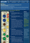
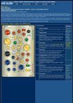
HOME
V700 PRO AUDIO
CLOSE
U794 HOME
EMAIL
PDF Version
User Manual
Harmonics Distortion Generator with Bandpass Filters U794
V700 Mastering Modules
Harmonics Distortion Generator Home | V700 Mastering Home
The Harmonics Distortion Generator U794 is available in different versions. Custom control ranges for several controls are
possible as well as different versions of the faceplate and the control knobs. The modules are available with electronically or
transformer balanced outputs. The inputs are always transformer balanced
For a general information on the module, please change over to the Harmonics Distortion Generator Homepage
Initial Settings | Quickstart | Options | FAQ's |
PDF Version
Control Elements
1
2
General Distortion k2
This control adds 2nd harmonics to the signal,
which means that components, 1 octave above
the original are added. The section operates
frequency independent, but the percentage of
harmonics depends on the input level. The
relation is not exactly linear. With higher levels,
the increase of distortion is a little lower.
(raising the level by 6 dB increases the
harmonics by approx. 2 dB). The control range
and law is well adapted and can add small
amounts of harmonics that are mostly used
precisely. 2nd harmonics are typical for all kinds
of active components, triodes, transistors, FETs
and practically everything else that can be use
for amplifcation. Adding k2 causes the same kind
of distortion as vintage tube amplifiers with
triodes.
General Distortion k3
This control adds 3rd harmonics (the quint
above the octave) to the original. The control
shifts a soft transition into a clipping curve that
is quite similar to the characteristics of a
pentode towards lower levels. The transition
range begins about 10 dB below the clipping
level. This part of the effect makes possible to
add the coloroísation of a pentode to the signal.
When set all to the right, the transition range
starts at 0 dBu. In addition, the input
transformer is treated in a way, that it produces
typical transformer distortion which occurs at
low frequencies only. The two effects are
adapted in a way that the reaction is quite
similar to a hard driven tube amplifier with
transformers and pentodes; however, this
control is not a tube sound simulator. It just
generates the same kind of harmonics
distortion. Like the k2 general control, this
control adds another interesting color to the
signal.
Notes and Pecularities
Over more than 50 years
of recording we all got
used to the typical side
effects of audio recording.
Distortion, mainly 2nd and
3rd harmonics a directly
connected not only to
amplification but to the
analog storage methods on
disc and tape.
When these effects are not
present, we usually don't
consider this as advantage.
In fact we do not
appreciate the absence of
the small percentage of
distortion we are used to,
which is described with
terms like 'warm' and
'musical'. We also don't
like too much of that kind
distortion; as soon as the
distortion reaches a certain
point, it's getting disturbing.
Though digital audio has
many disadvantages,
harmonics distortion is not
an issue with digital audio.
It's free from those effects.
Therefore adding a little
percentage of appropriate
distortion results in a mix
that subjectively sounds
better.
In addition, the balance
between 2nd and 3rd
harmonics is important for
the subjetive impression.
Two much of one or other,
againg results in this 'I'm
missing something' feeling.
3 to 9 - k2 Harmonics Generator and Filter
This section generates and adds 2nd harmonics. The high-pass (3/4) and low-pass
(5/6) filter control the frequency band that is fed to the generator. The drive control
(8) shifts the level at the input and output of the harmonics generator into an
appropriate range. The ADD k2 control (9) allows to add the generated harmonics
in phase (to the right) or phase reversed (to the left). At the center position of this
control no harmonics are added.
3
Low-pass Filter Control
The low-pass filter limits the frequency band pre
the harmonics generator. The control range
depends on the multiplier switch (4). With the
multiplier the sweep range covers the entire
audio band from 40 Hz to 20 kHz. Together with
the high pass filter, band-pass filtering is
possible.
High-pass and low-pass
filter together form a bandpass filter that allows
selection of any frequency
band in the audio
frequency range from 20
Hz to 20 kHz.
Generating distortion only
in a certain frequency band
4
Low-pass Filter Multiplier
this switch multiplies the frequency range of the
low pass filter control by 0.1 from 20 kHz - 400
Hz to 2 kHz - 40 Hz.
5
High-pass Filter Control
The high-pass filter limits the frequency band
pre the harmonics generator. The control range
depends on the multiplier switch (6). With the
multiplier the sweep range covers the entire
audio band from 20 Hz to 20 kHz. Together with
the low pass filter, band-pass filtering is
possible.
6
High-pass Filter Multiplier
this switch multiplies the frequency range of the
high pass filter control by 10 from 20 Hz - 2 Hz
to 200 Hz - 20 kHz.
7/8
Drive Control and Level Indicator
The Drive Control determines the operation level
of the harmonics generator section. Turning the
control to the right raises the input level of the
generator and reduces its output level and vice
versa. The control range is +/- 20 dB. The
operation level of the generator is cruicial for a
clean harmonics signal with sufficient output
level. The LED indicator displays the level in
relation the optimum drive of the generator.
With green color the level is too low (turn the
Drive control to the right), yellow to orange color
displays correct level, while red color indicates
clipping of the generator.
9
ADD k2
this control adds the output signal of the
harmonics generator to the original signal. At
the center position, no harmonics are added.
The range to the right adds distortion in phase;
the range to left adds phase reversed
distortion. Both methods result in different
effects with almost all audio signals. The scaling
of this control gives you an idea about the
percentage of harmonics you add; however, the
percentage of distortion depends on the level,
so the scaling is actually only relevant if the LED
indicator (7) is orange.
is the most effective way
to add interesting colors to
a mix. You can focus the
harmonics on the band that
offers the best effects,
without the need to
consider if other
frequencies cause negative
effects.
Generator Level and
Drive Control
The harmonics generator is
an almost ideal 4-quadrant
multiplier that squares the
input signal precisely.
Squaring results in
doubling the frequency,
which results in clean
octaves and not in a mix of
different harmonics;
however, squaring also
squares the voltage. If the
input voltage of the
generator is 1 V, the
output voltage is 1 V2, so
the output voltage is still 1
V. When the level is down
by 10 dB = 0.316 V the
output voltage is 0.316 V2
= 0.1 Volts. Raising the
voltage by 10 dB to 3.16 V
on the other hand changes
the output voltage to 3.16
V 2 = 10 Volts. It easy to
see that any input level
difference results in a
difference in the generated
harmonics of twice the dB
value. Since using the
filters can result in entirely
different levels at the
output of the filter section
it is necessary to adjust
the drive control, that can
shift the input level of the
generator into an
appropriate range for
propper operation.
10 to 16 - k3 Harmonics Generator and Filter
This section generates and adds 3rd harmonics. The high-pass (10/11) and lowpass (12/13) filter control the frequency band that is fed to the generator. The
drive control (14) shifts the level at the input and output of the harmonics
generator into an appropriate range. The ADD k3 control (16) allows to add the
generated harmonics in phase (to the right) or phase reversed (to the left). At the
center position of this control no harmonics are added.
10
Low-pass Filter Control
The low-pass filter limits the frequency band pre
the harmonics generator. The control range
depends on the multiplier switch (4). With the
multiplier the sweep range covers the entire
audio band from 40 Hz to 20 kHz. Together with
the high pass filter, band-pass filtering is
possible.
11
Low-pass Filter Multiplier
this switch multiplies the frequency range of the
low pass filter control by 0.1 from 20 kHz - 400
Hz to 2 kHz - 40 Hz.
12
High-pass Filter Control
The high-pass filter limits the frequency band
pre the harmonics generator. The control range
depends on the multiplier switch (6). With the
multiplier the sweep range covers the entire
audio band from 20 Hz to 20 kHz. Together with
the low pass filter, band-pass filtering is
possible.
13
High-pass Filter Multiplier
this switch multiplies the frequency range of the
high pass filter control by 10 from 20 Hz - 2 Hz
to 200 Hz - 20 kHz.
High-pass and low-pass
filter together form a bandpass filter that allows
selection of any frequency
band in the audio
frequency range from 20
Hz to 20 kHz.
Generating distortion only
in a certain frequency band
is the most effective way
to add interesting colors to
a mix. You can focus the
harmonics on that band,
that offers the best effects,
without the need to
consider if other
frequencies cause negative
effects.
Generator Level and
Drive Control
The harmonics generator is
an almost ideal 4-quadrant
multiplier that cubes the
input signal precisely.
Cubing results in
multiplying the frequency
by 3, which results in clean
14/15
Drive Control and Level Indicator
The Drive Control determines the operation level
of the harmonics generator section. Turning the
control to the right raises the the input level of
the generator and reduces its output level and
vice versa. The control range is +/- 20 dB. The
operation level of the generator is cruicial for an
clean harmonics signal with sufficient output
level. The LED indicator displays the level in
relation the optimum drive of the generator.
With green color the level is too low (turn the
Drive control to the right), yellow to orange color
displays correct level, while red color indicates
clipping of the generator.
16
ADD k2
this control adds the output signal of the
harmonics generator to the original signal. At
the center position, no harmonics are added.
The range to the right adds distortion in phase;
the range to left adds phase reversed
distortion. Both methods result in different
effects with almost all audio signals. The scaling
of this control gives you an idea about the
percentage of harmonics you add; however, the
percentage of distortion depends on the level,
so the scaling is actually only relevant if the LED
indicator (7) is orange.
17
ON Switch
This switch inserts the module. Unless the ON
swtich is pressed, the module is hard-bypassed
by relays. Input and output connectors are
bridges and the inputs and ouputs of the
module are switched away from the connectors.
The inputs do not load the driving source when
bypassed.
quints above the octave
and not in a mix of
different harmonics;
however, cubing also
cubes the voltage. If the
input voltage of the
generator is 1 V, the
output voltage is 1 V3, so
the output voltage is still 1
V. When the level is down
by 10 dB = 0.316 V the
output voltage is 0.316 V3
= 0.0316 Volts. Raising the
voltage by 10 dB to 3.16 V
on the other hand changes
the output voltage to 3.16
V 3 = 31.6 Volts which
means that the generator
clips. It is easy to see that
any input level difference
results in a difference in
the generated harmonics
of three times the dB
value. Since using the
filters can result in entirely
different levels at the
output of the filter section
it is necessary to adjust
the drive control, that can
shift the input level of the
generator into an
appropriate range for
propper operation.
Initial Setting
The following setting results in a neutral setting of all stages:
1. Insert the unit with the ON switch (17)
2. Set the General Distortion k2 control (1) all to the left (no distortion will be
added)
3. Set the General Distortion k3 control (2) all to the left (no distortion will be
added)
4. Set the ADD k2 control (9) to the 0 position (center - no distortion will be added)
5. Set the ADD k3 control (16) to the 0 position (center - no distortion will be
added)
6. Set the Drive Control (8) to the 0 position (center - no level shift)
7. Set the Drive Control (14) to the 0 position (center - no level shift)
8. Release the Mult switches (4, 6, 11, 13) of the filters
9. Set the low pass filter controls (3 / 10) all to the right
10. Set the high pass filter controls (5 / 12) all to the left
...TOP
Quickstart
a) Using the different functions of the harmonics generator depends on the taste of
the engineer and producer and on the structure mix. Therefore, there is no general
procedure for the adjustment.
b) Since the only problems that might come up are too much distortion in the
output signal and/or too high level on one of the harmonics generators, nothing
else has tobe considered that is of any importance.
c) Make sure that the drive controls (8 & 14) are set to a position where the level
indicators (7 & 15) are yellow to orange but not red, to make shure that the input
level of the generators is okay for propper operation. If the level throughout the
mix is not constant, use a high level passage for the setting.
...TOP
Options:
Control Ranges
We can adapt the control ranges to your needs. Please let us know what you are
looking for here.
Inputs and Outputs
The modules is available with electronically balanced and transformer balanced
outputs. The inputs are always transformer balances, since the input transformers
are included in the General k3 section.
Appearance
The colors of the faceplate, the control knobs, and switch caps can be determined
by the customer.
Please, check for details here.
...TOP
FAQ's
Why is the distortion level so different when I use the filters extensively?
The effect of different input levels on the harmonics generator section is explained
in detail in the boxes for k2 and k3. Please read the text to learn about the
background.
When using the filters extensively to cut out a small band, it depends on the
spectrum of the mix how this filter setting affects the output level. Usually the level
will drop dramatically when the frequency band is very small. Any kind of additional
regulation would result in some kind of compressor at the input of the generators
to keep the input level in a constant range. However, this would also result in an
entirely different behavior of the generators. Every time the level drops, the
regulator would drive up the level again, so the distortion would not drop down
with the level but remain constant or at least high, also with low input levels. Of
course there is no rule to determine a threshold level for the regulation in general,
since the filtering makes necessary that also very low levels that result from
filtering of small bands, can be processed. The only way out is to use the drive
control in combination with the level indicator.
Affects the General Distortion settings the k2 and k3 generators?
Yes, the output of the general distortion section drives both the k2 generator and
the k3 generator.
Affects the k2 setting the k3 generator?
No, only the general distortion section affects the generators. The k2 and the k3
section is driven from the output of the general distortion section. The outputs are
added directly to the output driver amplifier.
I've been using the drive control to shift the level up till the LED was red. The
harmonics are different but sound very nice. What happens with this setting?
When the LED indicator color becomes red, the input level will exceed the linear
operation range of the particular generator. With red color, you simply clip the
generator. It will not output clean k2 or k3 anymore but a mix of different
harmonics. The combination of the harmonics is different from the effect that occurs
when clipping a normal amplifier. In addition, both generators react differently.
There is no reason why you shouldn't use this range if the result is of advantage.
It's not the intended use, but you will not damage anything or get any
disadvantage from using that range.
The general k3 control is very intested; however, it would be a perfect thing if
there are some more controls to modify the behaviour. Is this possible?
Yes and no. The network that simulates the pentode is designed in a way, that the
transition range is very high to allow sensitive regulation and to produce high k3
and low k2 and k4 harmonics. If you tell us what you'de like, we can change this
network. There is no room for more controls on the faceplate of the U794 anymore,
so additional pots to modify the behaviour of the network are not possible. Please
have look at the U784 Colorizer that offers some different distortion effects. In
addition we are pondering on an additional device that offers one or two networks
with a full set of controls for the modification of the behaviour. If this module is of
interest for some customers, we're gonna make it in the near future.
If you have any questions or comments, please let us know.
...Top
V700 Index | Sitemap


![ACTIVALL - Instrukcja Obsługi_EN [w5] - Akces](http://vs1.manualzilla.com/store/data/005768844_1-d053a11c07508a5544c783645c43d650-150x150.png)